EP3531697A1 - Imaging camera and multi-eye imaging device - Google Patents
Imaging camera and multi-eye imaging device Download PDFInfo
- Publication number
- EP3531697A1 EP3531697A1 EP17861330.3A EP17861330A EP3531697A1 EP 3531697 A1 EP3531697 A1 EP 3531697A1 EP 17861330 A EP17861330 A EP 17861330A EP 3531697 A1 EP3531697 A1 EP 3531697A1
- Authority
- EP
- European Patent Office
- Prior art keywords
- image pickup
- holding member
- substrate
- recess
- securing material
- Prior art date
- Legal status (The legal status is an assumption and is not a legal conclusion. Google has not performed a legal analysis and makes no representation as to the accuracy of the status listed.)
- Granted
Links
Images






Classifications
-
- H—ELECTRICITY
- H04—ELECTRIC COMMUNICATION TECHNIQUE
- H04N—PICTORIAL COMMUNICATION, e.g. TELEVISION
- H04N13/00—Stereoscopic video systems; Multi-view video systems; Details thereof
- H04N13/20—Image signal generators
- H04N13/204—Image signal generators using stereoscopic image cameras
- H04N13/239—Image signal generators using stereoscopic image cameras using two two-dimensional [2D] image sensors having a relative position equal to or related to the interocular distance
-
- G—PHYSICS
- G02—OPTICS
- G02B—OPTICAL ELEMENTS, SYSTEMS OR APPARATUS
- G02B7/00—Mountings, adjusting means, or light-tight connections, for optical elements
- G02B7/02—Mountings, adjusting means, or light-tight connections, for optical elements for lenses
-
- G—PHYSICS
- G03—PHOTOGRAPHY; CINEMATOGRAPHY; ANALOGOUS TECHNIQUES USING WAVES OTHER THAN OPTICAL WAVES; ELECTROGRAPHY; HOLOGRAPHY
- G03B—APPARATUS OR ARRANGEMENTS FOR TAKING PHOTOGRAPHS OR FOR PROJECTING OR VIEWING THEM; APPARATUS OR ARRANGEMENTS EMPLOYING ANALOGOUS TECHNIQUES USING WAVES OTHER THAN OPTICAL WAVES; ACCESSORIES THEREFOR
- G03B19/00—Cameras
- G03B19/02—Still-picture cameras
- G03B19/04—Roll-film cameras
- G03B19/07—Roll-film cameras having more than one objective
-
- G—PHYSICS
- G03—PHOTOGRAPHY; CINEMATOGRAPHY; ANALOGOUS TECHNIQUES USING WAVES OTHER THAN OPTICAL WAVES; ELECTROGRAPHY; HOLOGRAPHY
- G03B—APPARATUS OR ARRANGEMENTS FOR TAKING PHOTOGRAPHS OR FOR PROJECTING OR VIEWING THEM; APPARATUS OR ARRANGEMENTS EMPLOYING ANALOGOUS TECHNIQUES USING WAVES OTHER THAN OPTICAL WAVES; ACCESSORIES THEREFOR
- G03B35/00—Stereoscopic photography
- G03B35/08—Stereoscopic photography by simultaneous recording
-
- H—ELECTRICITY
- H04—ELECTRIC COMMUNICATION TECHNIQUE
- H04N—PICTORIAL COMMUNICATION, e.g. TELEVISION
- H04N23/00—Cameras or camera modules comprising electronic image sensors; Control thereof
- H04N23/50—Constructional details
- H04N23/54—Mounting of pick-up tubes, electronic image sensors, deviation or focusing coils
-
- H—ELECTRICITY
- H04—ELECTRIC COMMUNICATION TECHNIQUE
- H04N—PICTORIAL COMMUNICATION, e.g. TELEVISION
- H04N23/00—Cameras or camera modules comprising electronic image sensors; Control thereof
- H04N23/50—Constructional details
- H04N23/55—Optical parts specially adapted for electronic image sensors; Mounting thereof
-
- H—ELECTRICITY
- H04—ELECTRIC COMMUNICATION TECHNIQUE
- H04N—PICTORIAL COMMUNICATION, e.g. TELEVISION
- H04N2213/00—Details of stereoscopic systems
- H04N2213/001—Constructional or mechanical details
Definitions
- the present invention relates to an image pickup camera and a multi-eye image pickup device, and relates to, for example, a coupling structure of a lens component and an image pickup element.
- PTL 1 JP 2014-179795 A discloses a solid-state image pickup device including a protruding portion on a wiring substrate. At a predetermined distance from an adhesion region between a holder and the wiring substrate, the protruding portion is formed along the adhesion region and adhesive for bonding the holder to the wiring substrate is applied to the protruding portion.
- PTL 2 JP 2008-191552 A discloses an adhesion connector for components to be mutually adhered, in which an end-edge portion of one component abuts to and adheres, with adhesive, to the other component. Each side in the thickness direction of the leading end of the end-edge portion has a recess formed thereon. An abutting protrusion between the recesses adheres to the other component with the adhesive, and the recess on each side houses an excess of the adhesive.
- PTL 1 or PTL 2 discloses the configuration of an image pickup camera in which a holder holding a lens and a wiring substrate on which an image pickup element is mounted are secured with adhesive.
- adhesive for the configuration of the image pickup camera described in PTL 1 or PTL 2, there is a risk that occurrence of flowing or separating of securing material, such as the adhesive, during manufacturing may cause soiling of the image pickup element, a crack, or a reduction in adhesion strength.
- the present invention has been made in consideration of the problem, and an object of the present invention is to provide an image pickup camera and a multi-eye image pickup device that can inhibit the flowing of securing material from occurring during manufacturing.
- An image pickup camera includes: a substrate on which an image pickup element is mounted; an optical lens configured to form a subject image on the image pickup element; a holding member holding the optical lens and surrounding a periphery of the image pickup element; and securing material securing the substrate and the holding member.
- the holding member has a coupling face that is a looped face opposed to the substrate and that is secured to the substrate through the securing material.
- One section in a loop direction of the coupling face includes a corner portion, and the holding member has a recess open toward the side of the image pickup element, at the corner portion.
- flowing of securing material can be inhibited from occurring during manufacturing.
- each embodiment including elemental steps
- constituent elements of each embodiment are not necessarily essential unless otherwise specified or obviously theoretically considered to be essential.
- shape and positional relationship of each constituent element in each embodiment unless otherwise specified or obviously theoretically contradicted, a shape substantially approximate to or similar to the shape thereof is included. This is applicable to the numerical value and the range, similarly.
- FIG. 1(a) is a perspective view of an exemplary schematic configuration of an image pickup camera according to a first embodiment of the present invention
- FIG. 1(b) is a plan view of an exemplary structure of a holding member in FIG. 1(a)
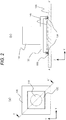
- FIG. 2(a) is a plan view of an exemplary outer shape of the image pickup camera of FIG. 1(a) that has been assembled
- FIG. 2(b) is a sectional view of an exemplary structure taken along line A-A' of FIG. 2(a) .
- the image pickup camera 100 illustrated in FIG. 1(a) includes an optical lens 110, the holding member 120, a substrate 130, an image pickup element 140, and securing material 150.
- the optical lens 110 is held and secured by the holding member 120, resulting in integration with the holding member 120.
- the substrate 130 has the image pickup element 140 mounted thereon, and the securing material 150 for securing the substrate 130 and the holding member 120 is applied on the periphery of the image pickup element 140 on the substrate 130.
- a representative example of the image pickup element 140 is a CMOS image sensor or a CCD image sensor.
- the holding member 120 has a bottom portion (coupling face) 121 that is a looped face opposed to the substrate 130 and that is secured to the substrate 130 through the securing material 150.
- One section in the loop direction of the bottom portion 121 includes a corner portion 122.
- the holding member 120 has a recess 124 open toward the image pickup element 140, at the corner portion 122.
- the bottom portion 121 includes four corner portions 122, and each of the four corner portions 122 is provided with the recess 124.
- the holding member 120 is secured to the substrate 130, through the securing material 150 in a state of surrounding the periphery of the image pickup element 140.
- the holding member 120 and the substrate 130 are secured such that the optical axis 160 of the optical lens 110 integrated with the holding member 120 is substantially perpendicular to the image pickup face of the image pickup element 140 and the focus of the optical lens 110 substantially agrees with the image pickup element 140.
- the securing material 150 in melt is applied to the substrate 130, and solidifies at a securing position determined between the holding member 120 and the substrate 130, resulting in securing of the holding member 120 and the substrate 130. It is considered that specific examples of the securing material 150 include any material that varies from melt to solidification, such as adhesive, resin, and solder.
- This arrangement enables the optical lens 110 to form visual information (subject image) acquired from outside, on the image pickup element 130, so that the image pickup camera 100 acquires an outside image.
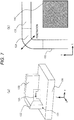
- FIG. 3(a) is a perspective view of exemplary shapes of the recess and the securing material in the image pickup camera of FIGS. 1(a) and 1(b)
- FIG. 3(b) is an enlarged plan view of a part of FIG. 3(a)
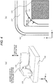
- FIGS. 4(a) and 4(b) illustrate a first comparative example of FIGS. 3(a) and 3(b) , respectively.
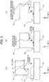
- FIGS. 5(a), 5(b), and 5(c) are sectional views for describing a mechanism for acquiring the shape of FIGS. 3(a) and 3(b) .
- the optical lens 110 and the image pickup element 140 has a positional relationship where the optical axis 160 of the optical lens 110 is perpendicular to the image pickup face of the image pickup element 140 and the focal position of the optical lens 110 agrees with the image pickup face of the image pickup element 140.
- the manufacturing process of the image pickup camera 100 includes a process of adjusting the positional relationship between the optical lens 110 and the image pickup element 140 and a process of solidifying the securing material 150 in melt at an adjusted position. As a result, desired optical performance is acquired.
- a holding member 120' with an optical lens, abutting on securing material 150 has no recess 124 at a corner portion 122, in some cases, the securing material 150 in melt accumulates at the corner portion of the holding member 120' due to surface tension. This phenomenon results from capillary action, and an inner wall located at the corner portion of the holding member 120' functions as a thin tube.
- Such a state causes, as illustrated in FIG. 4(b) , the securing material 150 that has accumulated at the corner portion, to flow and spread, resulting in adhesion of the securing material 150 to an image pickup element 140.
- the securing material 150 adhering thereto may cause soil of the image pickup element 140 or a crack due to thermal stress.
- the accumulation of the securing material 150 at the corner portion causes, in some cases, a reduction in the applied amount of the securing material 150 at side portions excluding the corner portion of the holding member 120'.
- occurrence of thinning or separating of the securing material 150 at the side portions of the holding member 120' may cause a reduction in securing strength.
- the holding member 120 in the image pickup camera 100 has the recess 124 open toward the image pickup element 140, at the corner portion.
- Such a structure causes a shape in which the securing material 150 at the corner portion is stored inside the recess 124, so that the securing material 150 is inhibited from accumulating not more than the capacity of the recess 124 at the corner portion.
- the securing material 150 is inhibited from flowing and spreading toward the image pickup element 140, so that the securing material 150 can be prevented from adhering to the image pickup element 140. Furthermore, the securing material 150 cannot accumulate at the corner portion greatly over the capacity of the recess 124. Thus, the securing material 150 is inhibited from reducing at the side portions, so that the securing material 150 can be prevented from thinning or separating.
- a mechanism of storing the securing material 150 at the corner portion inside the recess 124 can be described on the basis of the wetting and spreading behavior of the securing material 150 at the holding member 120.
- pressing the bottom portion (coupling face) 121 of the holding member 120 against the securing material 150 causes the recess 124 to suck the securing material 150 due to capillary action.
- the wetting shape of the securing material 150 is temporarily formed.
- the securing material 150 spreads wetly while generally keeping a wetting contact angle determined by the balance between the surface tension of the securing material 150, the surface tension of the holding member 120, and the interfacial tension between the securing material 150 and the holding member 120.
- the securing material 150 needs to spread wetly through the shape of the securing material 150 having a contact angle larger than that in the state of FIG. 5(b) .
- the size h2 in the height direction of the recess 124 is larger than the size h1 in the height direction of the securing material 150 that has been applied on the substrate 130. This is because, if the size h2 of the recess 124 is smaller than the size h1 of the securing material 150, there is a risk that the securing material 150 is likely to get over the edge EG1 at the instant when the holding member 120 is pressed against the securing material 150 as in FIG. 5(a) .
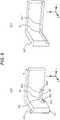
- FIG. 6(a) is a perspective view of an exemplary detailed structure of the holding member of FIG. 3(a)
- FIG. 6(b) is a perspective view of a second comparative example of FIG. 6(a)
- the recess 124 forms a space closed by a wall except for the side on which the image pickup element 140 is mounted.
- the recess 124 has the upper wall W1, side walls W2a and W2b, and a rear wall W3.
- the upper wall W1 is a wall intersecting with the perpendicular direction (Z-axis direction) of a face of the substrate 130.
- Each of the side walls W2a and W2b is a wall intersecting with the loop direction R of the bottom portion (coupling face) 121.
- the rear wall W3 is a wall intersecting with the direction from the inner circumferential side to the outer circumferential side of the bottom portion 121.
- the wetting of the securing material is deterred from getting over the edge EG1 of the upper wall W1 as described in FIG. 5(c) . Furthermore, because of a similar reason, the wetting of the securing material is deterred from getting over the edge EG2 of each of the side walls W2a and W2b.
- the two deterrents store the securing material inside the recess 124.
- flowing of the securing material 150 toward the image pickup element 140 can be inhibited from occurring during manufacturing. Furthermore, the securing material 150 is inhibited from reducing at the side portions, in accordance with the capacity of the recess 124, so that the securing material 150 can be prevented from thinning or separating. Prevention of the securing material 150 from thinning or separating, enables constant retention of the positional relationship between the holding member 120 (furthermore, the optical lens 110) and the substrate 130, and enables sufficient retention of the coupling strength between the holding member 120 and the substrate 130.
- FIG. 6(b) illustrates a holding member 120" having a recess, which is not limited to a corner portion, over the entire inner circumference of a bottom portion, differently from the structure of FIG. 6(a) .
- securing material spreads wetly in the recess from the corner portion as the starting point, similarly to the case of FIG. 4(a) .
- the edge EG1" of an upper wall W1" deters the wetting spread of the securing material, differently from the case of FIG. 4(a) .
- the side walls W2a and W2b each can catch, as tensile force, force in the perpendicular direction of the wall, as illustrated in FIG. 6(a) .
- the use of the structure of FIG. 6(a) allows, in some cases, further improvement of the coupling strength between the holding member 120 and the substrate 130 (particularly, shear strength) in comparison to the structure of FIG. 4(a) or the structure of FIG. 6(b) .
- FIG. 7(a) is a perspective view of an exemplary structure of the vicinity of a holding member in an image pickup camera according to a second embodiment of the present invention
- FIG. 7(b) is an enlarged plan view of a part of FIG. 7(a)
- the image pickup camera according to the second embodiment is different from the image pickup camera according to the first embodiment in terms of the shape of a recess 124 of the holding member 120.
- the recess 124 provided at a corner portion 122 forms a tunnel-like space penetrating between the inner circumference and the outer circumference of a looped bottom portion (coupling face) 121, with the holding member 120 secured to a substrate 130.
- the image pickup camera according to the second embodiment enables acquisition of a similar effect to that according to the first embodiment, and additionally causes securing material 150 to have more difficulty in accumulating on the image pickup element 140 side of the corner portion 124 in comparison to the case according to the first embodiment.
- the securing material 150 can be further inhibited from flowing and spreading toward the image pickup element 140. Note that, for example, depending on the quality of the securing material 150, external light possibly leaks toward the image pickup element 140 through the recess 124. Thus, from this point, the structure according to the first embodiment is preferable.
- FIG. 8(a) is a perspective view of an exemplary structure of the vicinity of a holding member in an image pickup camera according to a third embodiment of the present invention
- FIG. 8(b) is an enlarged plan view of a part of FIG. 8(a)
- the image pickup camera according to the third embodiment is different from the image pickup camera according to the first embodiment in that, as illustrated in FIGS. 8(a) and 8(b) , a plurality of recesses 124a, 124b, and 124c (here, three recesses) is provided at a corner portion 122 of the holding member 120.
- a recess 124 provided at the corner portion as illustrated in FIGS. 3(a) and 3(b) , functions as a capillary that sucks the securing material 150, and serves to confine the securing material 150 sucked, inside the recess 124.
- the capacity of the recess 124 is determined in consideration of, for example, how much of the total amount of the securing material 150 should be distributed to the side portions.
- the recess 124 requires increasing in capacity, for example, the interval between the side walls W2a and W2b illustrated in FIG. 6(a) requires widening.
- the recess 124 functions as a thick capillary.
- the suction force for the securing material 150 may be weakened, and additionally the confining force for the securing material 150 sucked inside the recess 124 may also be weakened.
- the provision of the plurality of recesses 124a, 124b, and 124c at the one corner portion 122 is advantageous.
- each of the recesses 124a, 124b, and 124c functioning as a thin capillary strongly sucks securing material 150, and additionally can confine the securing material 150 sucked inside the recess due to strong force.
- the image pickup camera according to the third embodiment enables acquisition of a similar effect to that according to the first embodiment, and additionally causes the plurality of recesses to actively to suck the securing material 150 due to capillary action and store the securing material 150 inside, in comparison to the case according to the first embodiment.
- the securing material 150 can be further inhibited from flowing and spreading toward an image pickup element 140. Even a case where the entire capacity of the recesses requires increasing to some extent can be handled, resulting in further improvement of the degree of freedom in determination of the capacity of the recesses.
- FIGS. 9(a) and 9(b) are respectively sectional views of an exemplary structure of the vicinity of a holding member in an image pickup camera according to a fourth embodiment of the present invention.
- the image pickup camera according to the fourth embodiment is different from the image pickup camera according to the first embodiment in terms of the shape of a recess 124 of the holding member 120.
- FIGS. 9(a) and 9(b) illustrate that the recess 124 is further provided with a second recess 125.
- the recess 124 and the second recess 125 form a stepwise stage when viewed on a plane (XZ plane) in the perpendicular direction of a face of a substrate 130.
- the provision of the second recess 125 causes stepwise disposition of upper walls W11 and W12 and edges EG11 and EG12.
- the edge EG12 can deter the wetting of the securing material.
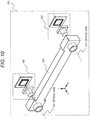
- FIG. 10 is a perspective view of an exemplary schematic configuration of a multi-eye image pickup device according to a fifth embodiment of the present invention.
- the multi-eye image pickup device 400 illustrated in FIG. 10 includes an image pickup camera 100, a second image pickup camera 200, and a casing 300.
- the second image pickup camera 200 has a structure equivalent to that of the image pickup camera 100.
- the casing 300 secures the image pickup camera 100 and the second image pickup camera 200 at positions separated by a predetermined distance such that the respective optical axes 160 of the image pickup camera 100 and the second image pickup camera 200 are substantially parallel.
- the multi-eye image pickup device 400 detects identical points between respective images acquired by the image pickup camera 100 and the second image pickup camera 200 and combines both of the images, to generate a range image including outside three-dimensional information.
- the respective optical characteristics of the image pickup cameras include in the multi-eye image pickup device 400 are preferably identical.
- An example of the optical characteristic of each image pickup camera related to the acquisition of the range information is the response characteristic of a focal position to temperature (hereinafter, referred to as a defocus temperature characteristic).
- a defocus temperature characteristic For example, in a case where there is a large difference between the respective defocus temperature characteristics of the image pickup cameras included in the multi-eye image pickup device 400, a variation occurs in resolution between respective images acquired by the image pickup cameras when the outside temperature varies. Such a state causes the multi-eye image pickup device 400 to have difficulty in detecting identical points between the respective images acquired by the image pickup cameras, resulting in deterioration in accuracy of calculating a range in a generated range image.
- the optical characteristic such as the defocus temperature characteristic, depends on the structure or configuration of an optical lens, a holding member, securing material, an image pickup element, and a substrate included in the image pickup camera.
- the securing material applied in melt during manufacturing accumulates at a corner portion of the holding member and causes a variation in shape.
- the securing material is a main factor for a variation in optical characteristic.
- FIG. 11 is a sectional view of an exemplary schematic structure of the multi-eye image pickup device of FIG. 10
- FIG. 12 is a sectional view of a comparative example of FIG. 11
- each of an image pickup camera 100' and a second image pickup camera 200' includes the holding member 120' illustrated in FIGS. 4(a) and 4(b) . In this case, as illustrated in FIG.
- the respective optical axes 160 of the image pickup camera 100' and the second image pickup camera 200' are not parallel, resulting in an event in which the positional relationship between an optical lens 110 and an image pickup element 140 of the image pickup camera 100' is different from the positional relationship between an optical lens 110 and an image pickup element 140 of the second image pickup camera 200'.
- the image pickup element 140 in one of the two image pickup cameras is available for focusing, and it may be difficult to detect identical points between respective images acquired by the image pickup cameras.
- the example of FIG. 12 indicates the image pickup camera 100' having a difference in the accumulation amount of securing material 150 between two corner portions due to occurrence of misalignment during pressing the holding member 120' against the securing material 150.
- the difference causes, in some cases, for example, that the amount of the securing material 150 at side portions of the holding member 120' is different every side portion.
- the optical axis 160 may incline.
- the difference in the accumulation amount of securing material 150 between the two corner portions causes, in some cases, adhesion force at the two corner portions to vary along with outside temperature. As a result, even if the optical axis 160 has no inclination during manufacturing, the optical axis 160 may incline along with a variation in outside temperature.
- use of the multi-eye image pickup device enables, as described in each embodiment, substantially constant retention of the accumulation amount of securing material 150 at each corner portion, in accordance with the capacity of a recess 124.
- This arrangement enables substantially constant retention of the amount of the securing material 150 at side portions of each holding member 120, at each side portion, and enables substantially constant retention of adhesion force at each corner portion regardless of outside temperature.
- the optical axes 160 of the image pickup camera 100 and the second image pickup camera 200 can be retained in parallel, so that identical points between respective images acquired by the image pickup cameras can be detected easily.
- the use of the multi-eye image pickup device according to the fifth embodiment enables acquisition of a similar effect to those according to the first to fourth embodiments, and additionally enables inhibition of a variation in the shape of the securing material in each image pickup camera.
- the range calculating accuracy of the multi-eye image pickup device can be prevented from deteriorating due to a factor, such as a variation in temperature.
- the planar shape formed with the inner circumference of the bottom portion (coupling face) of the holding member is a quadrangle having four corner portions.
- the planar shape is not limited to the quadrangle, and is required at least to have a shape having at least one corner portion.
- the corner portion has two lines intersecting at an angle of ⁇ (0 ⁇ ⁇ ⁇ 180°).
Landscapes
- Physics & Mathematics (AREA)
- General Physics & Mathematics (AREA)
- Engineering & Computer Science (AREA)
- Multimedia (AREA)
- Signal Processing (AREA)
- Optics & Photonics (AREA)
- Lens Barrels (AREA)
- Studio Devices (AREA)
- Stereoscopic And Panoramic Photography (AREA)
- Cameras In General (AREA)
- Transforming Light Signals Into Electric Signals (AREA)
Abstract
Description
- The present invention relates to an image pickup camera and a multi-eye image pickup device, and relates to, for example, a coupling structure of a lens component and an image pickup element.
- For example, PTL 1 (
JP 2014-179795 A JP 2008-191552 A -
- PTL 1:
JP 2014-179795 A - PTL 2:
JP 2008-191552 A - PTL 1 or PTL 2 discloses the configuration of an image pickup camera in which a holder holding a lens and a wiring substrate on which an image pickup element is mounted are secured with adhesive. However, for the configuration of the image pickup camera described in PTL 1 or PTL 2, there is a risk that occurrence of flowing or separating of securing material, such as the adhesive, during manufacturing may cause soiling of the image pickup element, a crack, or a reduction in adhesion strength.
- The present invention has been made in consideration of the problem, and an object of the present invention is to provide an image pickup camera and a multi-eye image pickup device that can inhibit the flowing of securing material from occurring during manufacturing.
- The object, another object, and novel features of the present invention will be clarified with the descriptions herein and the accompanying drawings.
- An outline of a representative embodiment in the invention disclosed in the present application is simply given as follows:
- An image pickup camera according to an embodiment includes: a substrate on which an image pickup element is mounted; an optical lens configured to form a subject image on the image pickup element; a holding member holding the optical lens and surrounding a periphery of the image pickup element; and securing material securing the substrate and the holding member. The holding member has a coupling face that is a looped face opposed to the substrate and that is secured to the substrate through the securing material. One section in a loop direction of the coupling face includes a corner portion, and the holding member has a recess open toward the side of the image pickup element, at the corner portion.
- According to the embodiment described above, flowing of securing material can be inhibited from occurring during manufacturing.
-
-
FIG. 1(a) is a perspective view of an exemplary schematic configuration of an image pickup camera according to a first embodiment of the present invention, andFIG. 1(b) is a plan view of an exemplary structure of a holding member inFIG. 1(a) . -
FIG. 2(a) is a plan view of an exemplary outer shape of the image pickup camera ofFIG. 1(a) that has been assembled, andFIG. 2(b) is a sectional view of an exemplary structure taken along line A-A' ofFIG. 2(a) . -
FIG. 3] FIG. 3(a) is a perspective view of exemplary shapes of a recess and securing material in the image pickup camera ofFIGS. 1(a) and 1(b) , andFIG. 3(b) is an enlarged plan view of a part ofFIG. 3(a) . -
FIGS. 4(a) and 4(b) illustrate a first comparative example ofFIGS. 3(a) and 3(b) , respectively. -
FIGS. 5(a), 5(b), and 5(c) are sectional views for describing a mechanism for acquiring the shapes inFIGS. 3(a) and 3(b) . -
FIG. 6(a) is a perspective view of an exemplary detailed structure of the holding member ofFIG. 3(a) , andFIG. 6(b) is a perspective view of a second comparative example ofFIG. 6(a) . -
FIG. 7(a) is a perspective view of an exemplary structure of the vicinity of a holding member in an image pickup camera according to a second embodiment of the present invention, andFIG. 7(b) is an enlarged plan view of a part ofFIG. 7(a) . -
FIG. 8(a) is a perspective view of an exemplary structure of the vicinity of a holding member in an image pickup camera according to a third embodiment of the present invention, andFIG. 8(b) is an enlarged plan view of a part ofFIG. 8(a) . -
FIGS. 9(a) and 9(b) are respectively sectional views of an exemplary structure of the vicinity of a holding member in an image pickup camera according to a fourth embodiment of the present invention. -
FIG. 10 is a perspective view of an exemplary schematic configuration of a multi-eye image pickup device according to a fifth embodiment of the present invention. -
FIG. 11 is a sectional view of an exemplary schematic structure of the multi-eye image pickup device ofFIG. 10 . -
FIG. 12 is a sectional view of a comparative example ofFIG. 11 . - Each embodiment will be described, as necessary for convenience, with division into a plurality of sections or a plurality of embodiments. Unless otherwise specified, those are related to each other. For example, one is related to a modification, detail, or supplementary explanation of the entirety or part of another. In a case where referring to the number of elements (including number of pieces, numerical value, quantity, and range are included) in each embodiment, unless otherwise specified or obviously theoretically limited to a specific number, the number of elements is not limited to the specific number, and thus may be not less than or not more than the specific number.
- Furthermore, needless to say, the constituent elements of each embodiment (including elemental steps) are not necessarily essential unless otherwise specified or obviously theoretically considered to be essential. Similarly, when referring to the shape and positional relationship of each constituent element in each embodiment, unless otherwise specified or obviously theoretically contradicted, a shape substantially approximate to or similar to the shape thereof is included. This is applicable to the numerical value and the range, similarly.
- The embodiments of the present invention will be described in detail below on the basis of the drawings. Note that the same members are denoted with the same reference signs, in principle, in all figures for describing the embodiments, and the descriptions thereof will not be repeated.
-
FIG. 1(a) is a perspective view of an exemplary schematic configuration of an image pickup camera according to a first embodiment of the present invention, andFIG. 1(b) is a plan view of an exemplary structure of a holding member inFIG. 1(a) .FIG. 2(a) is a plan view of an exemplary outer shape of the image pickup camera ofFIG. 1(a) that has been assembled, andFIG. 2(b) is a sectional view of an exemplary structure taken along line A-A' ofFIG. 2(a) . - The
image pickup camera 100 illustrated inFIG. 1(a) includes anoptical lens 110, theholding member 120, asubstrate 130, animage pickup element 140, and securingmaterial 150. Theoptical lens 110 is held and secured by theholding member 120, resulting in integration with theholding member 120. Thesubstrate 130 has theimage pickup element 140 mounted thereon, and thesecuring material 150 for securing thesubstrate 130 and theholding member 120 is applied on the periphery of theimage pickup element 140 on thesubstrate 130. A representative example of theimage pickup element 140 is a CMOS image sensor or a CCD image sensor. - As illustrated in
FIG. 1(b) , theholding member 120 has a bottom portion (coupling face) 121 that is a looped face opposed to thesubstrate 130 and that is secured to thesubstrate 130 through thesecuring material 150. One section in the loop direction of thebottom portion 121 includes acorner portion 122. Here, theholding member 120 has arecess 124 open toward theimage pickup element 140, at thecorner portion 122. In this example, thebottom portion 121 includes fourcorner portions 122, and each of the fourcorner portions 122 is provided with therecess 124. - As illustrated in
FIGS. 1(a), 1(b) , and2(b) , with the bottom portion (coupling face) 121 of theholding member 120 abutting on the securingmaterial 150, theholding member 120 is secured to thesubstrate 130, through the securingmaterial 150 in a state of surrounding the periphery of theimage pickup element 140. At this time, theholding member 120 and thesubstrate 130 are secured such that theoptical axis 160 of theoptical lens 110 integrated with theholding member 120 is substantially perpendicular to the image pickup face of theimage pickup element 140 and the focus of theoptical lens 110 substantially agrees with theimage pickup element 140. - During manufacturing, the
securing material 150 in melt is applied to thesubstrate 130, and solidifies at a securing position determined between theholding member 120 and thesubstrate 130, resulting in securing of theholding member 120 and thesubstrate 130. It is considered that specific examples of the securingmaterial 150 include any material that varies from melt to solidification, such as adhesive, resin, and solder. - This arrangement enables the
optical lens 110 to form visual information (subject image) acquired from outside, on theimage pickup element 130, so that theimage pickup camera 100 acquires an outside image. -
FIG. 3(a) is a perspective view of exemplary shapes of the recess and the securing material in the image pickup camera ofFIGS. 1(a) and 1(b) , andFIG. 3(b) is an enlarged plan view of a part ofFIG. 3(a) .FIGS. 4(a) and 4(b) illustrate a first comparative example ofFIGS. 3(a) and 3(b) , respectively.FIGS. 5(a), 5(b), and 5(c) are sectional views for describing a mechanism for acquiring the shape ofFIGS. 3(a) and 3(b) . - For the
image pickup camera 100, generally, it is ideal that theoptical lens 110 and theimage pickup element 140 has a positional relationship where theoptical axis 160 of theoptical lens 110 is perpendicular to the image pickup face of theimage pickup element 140 and the focal position of theoptical lens 110 agrees with the image pickup face of theimage pickup element 140. In order to achieve such a positional relationship, the manufacturing process of theimage pickup camera 100 includes a process of adjusting the positional relationship between theoptical lens 110 and theimage pickup element 140 and a process of solidifying the securingmaterial 150 in melt at an adjusted position. As a result, desired optical performance is acquired. - However, as illustrated in
FIG. 4(a) , if a holding member 120' with an optical lens, abutting on securingmaterial 150 has norecess 124 at acorner portion 122, in some cases, the securingmaterial 150 in melt accumulates at the corner portion of the holding member 120' due to surface tension. This phenomenon results from capillary action, and an inner wall located at the corner portion of the holding member 120' functions as a thin tube. - Such a state causes, as illustrated in
FIG. 4(b) , the securingmaterial 150 that has accumulated at the corner portion, to flow and spread, resulting in adhesion of the securingmaterial 150 to animage pickup element 140. There is a risk that the securingmaterial 150 adhering thereto may cause soil of theimage pickup element 140 or a crack due to thermal stress. Furthermore, the accumulation of the securingmaterial 150 at the corner portion causes, in some cases, a reduction in the applied amount of the securingmaterial 150 at side portions excluding the corner portion of the holding member 120'. As a result, there is a risk that occurrence of thinning or separating of the securingmaterial 150 at the side portions of the holding member 120' may cause a reduction in securing strength. - Thus, as illustrated in
FIGS. 3(a) and 3(b) , the holdingmember 120 in theimage pickup camera 100 according to the first embodiment has therecess 124 open toward theimage pickup element 140, at the corner portion. Such a structure causes a shape in which the securingmaterial 150 at the corner portion is stored inside therecess 124, so that the securingmaterial 150 is inhibited from accumulating not more than the capacity of therecess 124 at the corner portion. - As a result, as illustrated in
FIG. 3(b) , the securingmaterial 150 is inhibited from flowing and spreading toward theimage pickup element 140, so that the securingmaterial 150 can be prevented from adhering to theimage pickup element 140. Furthermore, the securingmaterial 150 cannot accumulate at the corner portion greatly over the capacity of therecess 124. Thus, the securingmaterial 150 is inhibited from reducing at the side portions, so that the securingmaterial 150 can be prevented from thinning or separating. - A mechanism of storing the securing
material 150 at the corner portion inside therecess 124 can be described on the basis of the wetting and spreading behavior of the securingmaterial 150 at the holdingmember 120. As illustrated inFIG. 5(a) , pressing the bottom portion (coupling face) 121 of the holdingmember 120 against the securingmaterial 150, causes therecess 124 to suck the securingmaterial 150 due to capillary action. As illustrated inFIG. 5(b) , the wetting shape of the securingmaterial 150 is temporarily formed. - As illustrated in
FIG. 5(b) , in a state where the securingmaterial 150 adheres to the upper wall W1 of therecess 124, the securingmaterial 150 spreads wetly while generally keeping a wetting contact angle determined by the balance between the surface tension of the securingmaterial 150, the surface tension of the holdingmember 120, and the interfacial tension between the securingmaterial 150 and the holdingmember 120. However, for wetting spread of the securingmaterial 150 over the edge EG1 of the upper wall W1, as illustrated inFIG. 5(c) , the securingmaterial 150 needs to spread wetly through the shape of the securingmaterial 150 having a contact angle larger than that in the state ofFIG. 5(b) . - For the wetting spread through such a shape of the securing
material 150, a large supply of securingmaterial 150 and driving force for strong wetting spread are required in comparison to the state ofFIG. 5(b) . Thus, the securingmaterial 150 that has risen wetly at the corner portion due to the capillary action cannot get over the edge EG1 of therecess 124 formed at the corner portion. This mechanism causes therecess 124 to suck the securingmaterial 150, resulting in further storage of the securingmaterial 150 inside therecess 124. - Note that, in
FIG. 5(a) , preferably, the size h2 in the height direction of therecess 124 is larger than the size h1 in the height direction of the securingmaterial 150 that has been applied on thesubstrate 130. This is because, if the size h2 of therecess 124 is smaller than the size h1 of the securingmaterial 150, there is a risk that the securingmaterial 150 is likely to get over the edge EG1 at the instant when the holdingmember 120 is pressed against the securingmaterial 150 as inFIG. 5(a) . -
FIG. 6(a) is a perspective view of an exemplary detailed structure of the holding member ofFIG. 3(a) , andFIG. 6(b) is a perspective view of a second comparative example ofFIG. 6(a) . As described above, with the holdingmember 120 secured to thesubstrate 130, therecess 124 forms a space closed by a wall except for the side on which theimage pickup element 140 is mounted. Specifically, as illustrated inFIG. 6(a) , therecess 124 has the upper wall W1, side walls W2a and W2b, and a rear wall W3. The upper wall W1 is a wall intersecting with the perpendicular direction (Z-axis direction) of a face of thesubstrate 130. Each of the side walls W2a and W2b is a wall intersecting with the loop direction R of the bottom portion (coupling face) 121. The rear wall W3 is a wall intersecting with the direction from the inner circumferential side to the outer circumferential side of thebottom portion 121. - In
FIG. 6(a) , the wetting of the securing material is deterred from getting over the edge EG1 of the upper wall W1 as described inFIG. 5(c) . Furthermore, because of a similar reason, the wetting of the securing material is deterred from getting over the edge EG2 of each of the side walls W2a and W2b. The two deterrents store the securing material inside therecess 124. - As a result, as described above, flowing of the securing
material 150 toward theimage pickup element 140 can be inhibited from occurring during manufacturing. Furthermore, the securingmaterial 150 is inhibited from reducing at the side portions, in accordance with the capacity of therecess 124, so that the securingmaterial 150 can be prevented from thinning or separating. Prevention of the securingmaterial 150 from thinning or separating, enables constant retention of the positional relationship between the holding member 120 (furthermore, the optical lens 110) and thesubstrate 130, and enables sufficient retention of the coupling strength between the holdingmember 120 and thesubstrate 130. - Meanwhile,
FIG. 6(b) illustrates a holdingmember 120" having a recess, which is not limited to a corner portion, over the entire inner circumference of a bottom portion, differently from the structure ofFIG. 6(a) . In this case, securing material spreads wetly in the recess from the corner portion as the starting point, similarly to the case ofFIG. 4(a) . On this occasion, the edge EG1" of an upper wall W1" deters the wetting spread of the securing material, differently from the case ofFIG. 4(a) . - However, the deterrent due to the edge EG2 of each side wall in the structure of
FIG. 6(a) does not work in the structure ofFIG. 6(b) . Thus, the deterrent to the wetting spread of the securing material is insufficient, so that the securing material may not be sufficiently inhibited from flowing and spreading toward an image pickup element. Because no side walls W2a and W2b are provided, the accumulation amount of the securing material to the corner portion is difficult to control. Thus, there is a risk that the securingmaterial 150 may become thin or separate at side portions. Thus, use of the structure as inFIG. 6(a) is advantageous. - Note that, in a case where the securing material solidifies in the
recess 124 ofFIG. 6(a) , the side walls W2a and W2b each can catch, as tensile force, force in the perpendicular direction of the wall, as illustrated inFIG. 6(a) . As a result, the use of the structure ofFIG. 6(a) allows, in some cases, further improvement of the coupling strength between the holdingmember 120 and the substrate 130 (particularly, shear strength) in comparison to the structure ofFIG. 4(a) or the structure ofFIG. 6(b) . -
FIG. 7(a) is a perspective view of an exemplary structure of the vicinity of a holding member in an image pickup camera according to a second embodiment of the present invention, andFIG. 7(b) is an enlarged plan view of a part ofFIG. 7(a) . The image pickup camera according to the second embodiment is different from the image pickup camera according to the first embodiment in terms of the shape of arecess 124 of the holdingmember 120. InFIGS. 7(a) and 7(b) , therecess 124 provided at acorner portion 122 forms a tunnel-like space penetrating between the inner circumference and the outer circumference of a looped bottom portion (coupling face) 121, with the holdingmember 120 secured to asubstrate 130. - Use of the image pickup camera according to the second embodiment enables acquisition of a similar effect to that according to the first embodiment, and additionally causes securing
material 150 to have more difficulty in accumulating on theimage pickup element 140 side of thecorner portion 124 in comparison to the case according to the first embodiment. Thus, in some cases, the securingmaterial 150 can be further inhibited from flowing and spreading toward theimage pickup element 140. Note that, for example, depending on the quality of the securingmaterial 150, external light possibly leaks toward theimage pickup element 140 through therecess 124. Thus, from this point, the structure according to the first embodiment is preferable. -
FIG. 8(a) is a perspective view of an exemplary structure of the vicinity of a holding member in an image pickup camera according to a third embodiment of the present invention, andFIG. 8(b) is an enlarged plan view of a part ofFIG. 8(a) . The image pickup camera according to the third embodiment is different from the image pickup camera according to the first embodiment in that, as illustrated inFIGS. 8(a) and 8(b) , a plurality ofrecesses corner portion 122 of the holdingmember 120. - For example, a
recess 124 provided at the corner portion as illustrated inFIGS. 3(a) and 3(b) , functions as a capillary that sucks the securingmaterial 150, and serves to confine the securingmaterial 150 sucked, inside therecess 124. The capacity of therecess 124 is determined in consideration of, for example, how much of the total amount of the securingmaterial 150 should be distributed to the side portions. Here, if therecess 124 requires increasing in capacity, for example, the interval between the side walls W2a and W2b illustrated inFIG. 6(a) requires widening. - In this case, the
recess 124 functions as a thick capillary. Thus, there is a risk that the suction force for the securingmaterial 150 may be weakened, and additionally the confining force for the securingmaterial 150 sucked inside therecess 124 may also be weakened. Thus, as inFIGS. 8(a) and 8(b) , the provision of the plurality ofrecesses corner portion 122 is advantageous. In this case, each of therecesses material 150, and additionally can confine the securingmaterial 150 sucked inside the recess due to strong force. - Use of the image pickup camera according to the third embodiment enables acquisition of a similar effect to that according to the first embodiment, and additionally causes the plurality of recesses to actively to suck the securing
material 150 due to capillary action and store the securingmaterial 150 inside, in comparison to the case according to the first embodiment. Thus, the securingmaterial 150 can be further inhibited from flowing and spreading toward animage pickup element 140. Even a case where the entire capacity of the recesses requires increasing to some extent can be handled, resulting in further improvement of the degree of freedom in determination of the capacity of the recesses. -
FIGS. 9(a) and 9(b) are respectively sectional views of an exemplary structure of the vicinity of a holding member in an image pickup camera according to a fourth embodiment of the present invention. The image pickup camera according to the fourth embodiment is different from the image pickup camera according to the first embodiment in terms of the shape of arecess 124 of the holdingmember 120.FIGS. 9(a) and 9(b) illustrate that therecess 124 is further provided with asecond recess 125. Therecess 124 and thesecond recess 125 form a stepwise stage when viewed on a plane (XZ plane) in the perpendicular direction of a face of asubstrate 130. - Use of the image pickup camera according to the fourth embodiment enables acquisition of a similar effect to that according to the first embodiment, and additionally enables further reliable storage of securing
material 150 inside therecess 124 in comparison to the case according to the first embodiment. Specifically, as described inFIG. 5(a) , for example, in a case where the size h1 in the height direction of the securingmaterial 150 is larger than the size h2 in the height direction of therecess 124 due to a factor of some kind, there is a risk that the securingmaterial 150 may get over the edge EG1. Meanwhile, inFIG. 9(a) (similarly, inFIG. 9(b) ), the provision of thesecond recess 125 causes stepwise disposition of upper walls W11 and W12 and edges EG11 and EG12. Thus, even if the securingmaterial 150 gets over the edge EG11, the edge EG12 can deter the wetting of the securing material. -
FIG. 10 is a perspective view of an exemplary schematic configuration of a multi-eye image pickup device according to a fifth embodiment of the present invention. The multi-eyeimage pickup device 400 illustrated inFIG. 10 includes animage pickup camera 100, a secondimage pickup camera 200, and acasing 300. The secondimage pickup camera 200 has a structure equivalent to that of theimage pickup camera 100. Thecasing 300 secures theimage pickup camera 100 and the secondimage pickup camera 200 at positions separated by a predetermined distance such that the respectiveoptical axes 160 of theimage pickup camera 100 and the secondimage pickup camera 200 are substantially parallel. - The multi-eye
image pickup device 400 detects identical points between respective images acquired by theimage pickup camera 100 and the secondimage pickup camera 200 and combines both of the images, to generate a range image including outside three-dimensional information. Thus, when the multi-eyeimage pickup device 400 acquires outside range information, the respective optical characteristics of the image pickup cameras include in the multi-eyeimage pickup device 400 are preferably identical. - An example of the optical characteristic of each image pickup camera related to the acquisition of the range information is the response characteristic of a focal position to temperature (hereinafter, referred to as a defocus temperature characteristic). For example, in a case where there is a large difference between the respective defocus temperature characteristics of the image pickup cameras included in the multi-eye
image pickup device 400, a variation occurs in resolution between respective images acquired by the image pickup cameras when the outside temperature varies. Such a state causes the multi-eyeimage pickup device 400 to have difficulty in detecting identical points between the respective images acquired by the image pickup cameras, resulting in deterioration in accuracy of calculating a range in a generated range image. - The optical characteristic, such as the defocus temperature characteristic, depends on the structure or configuration of an optical lens, a holding member, securing material, an image pickup element, and a substrate included in the image pickup camera. In particular, as described above, the securing material applied in melt during manufacturing accumulates at a corner portion of the holding member and causes a variation in shape. Thus, the securing material is a main factor for a variation in optical characteristic. Thus, application of any of the configurations described in the first to fourth embodiments to each of the
image pickup camera 100 and the secondimage pickup camera 200 is advantageous. -
FIG. 11 is a sectional view of an exemplary schematic structure of the multi-eye image pickup device ofFIG. 10 , andFIG. 12 is a sectional view of a comparative example ofFIG. 11 . According to the comparative example ofFIG. 12 , each of an image pickup camera 100' and a second image pickup camera 200' includes the holding member 120' illustrated inFIGS. 4(a) and 4(b) . In this case, as illustrated inFIG. 12 , the respectiveoptical axes 160 of the image pickup camera 100' and the second image pickup camera 200' are not parallel, resulting in an event in which the positional relationship between anoptical lens 110 and animage pickup element 140 of the image pickup camera 100' is different from the positional relationship between anoptical lens 110 and animage pickup element 140 of the second image pickup camera 200'. As a result, only theimage pickup element 140 in one of the two image pickup cameras is available for focusing, and it may be difficult to detect identical points between respective images acquired by the image pickup cameras. - The example of
FIG. 12 indicates the image pickup camera 100' having a difference in the accumulation amount of securingmaterial 150 between two corner portions due to occurrence of misalignment during pressing the holding member 120' against the securingmaterial 150. The difference causes, in some cases, for example, that the amount of the securingmaterial 150 at side portions of the holding member 120' is different every side portion. Thus, there is a risk that theoptical axis 160 may incline. Furthermore, the difference in the accumulation amount of securingmaterial 150 between the two corner portions causes, in some cases, adhesion force at the two corner portions to vary along with outside temperature. As a result, even if theoptical axis 160 has no inclination during manufacturing, theoptical axis 160 may incline along with a variation in outside temperature. - Meanwhile, use of the multi-eye image pickup device according to the fifth embodiment, enables, as described in each embodiment, substantially constant retention of the accumulation amount of securing
material 150 at each corner portion, in accordance with the capacity of arecess 124. This arrangement enables substantially constant retention of the amount of the securingmaterial 150 at side portions of each holdingmember 120, at each side portion, and enables substantially constant retention of adhesion force at each corner portion regardless of outside temperature. As a result, as illustrated inFIG. 11 , theoptical axes 160 of theimage pickup camera 100 and the secondimage pickup camera 200 can be retained in parallel, so that identical points between respective images acquired by the image pickup cameras can be detected easily. - The use of the multi-eye image pickup device according to the fifth embodiment enables acquisition of a similar effect to those according to the first to fourth embodiments, and additionally enables inhibition of a variation in the shape of the securing material in each image pickup camera. Thus, the range calculating accuracy of the multi-eye image pickup device can be prevented from deteriorating due to a factor, such as a variation in temperature.
- The present invention made by the present inventors has been specifically described above on the basis of the embodiments. However, the present invention is not limited to the embodiments, and thus various alternations may be made without departing from the spirit of the present invention. For example, the embodiments have been described in detail for easy understanding of the present invention, and thus any one of the embodiments is not necessarily limited to including the described entire configuration. A part of the configuration of an embodiment may be replaced with the configuration of another embodiment, or the configuration of an embodiment may be added to the configuration of another embodiment. Addition, deletion, or replacement of another embodiment may be made to a part of the configuration of each embodiment.
- For example, according to each embodiment described above, the case where the planar shape formed with the inner circumference of the bottom portion (coupling face) of the holding member is a quadrangle having four corner portions has been exemplified. Note that the planar shape is not limited to the quadrangle, and is required at least to have a shape having at least one corner portion. For example, even when the planar shape is entirely substantially circular, if a corner portion is present for some reason in the section of part thereof, application of each embodiment described above enables occurrence of a similar phenomenon advantageously. Note that the corner portion has two lines intersecting at an angle of θ (0 < θ < 180°).
-
- 100
- image pickup camera
- 110
- optical lens
- 120
- holding member
- 121
- bottom portion (coupling face)
- 122
- corner portion
- 123
- side portion
- 124, 124a, 124b, 124c
- recess
- 125
- second recess
- 130
- substrate
- 140
- image pickup element
- 150
- securing material
- 160
- optical axis
- 200
- second image pickup camera
- 300
- casing
- 400
- multi-eye image pickup device
- EG1, EG2, EG11, EG12
- edge
- W1, W2a, W2b, W3, W11, W12
- wall
Claims (12)
- An image pickup camera comprising:a substrate on which an image pickup element is mounted;an optical lens configured to form a subject image on the image pickup element;a holding member holding the optical lens and surrounding a periphery of the image pickup element; andsecuring material securing the substrate and the holding member,wherein the holding member has a coupling face that is a looped face opposed to the substrate, the coupling face being secured to the substrate through the securing material,one section in a loop direction of the coupling face includes a corner portion, andthe holding member has a recess open toward a side of the image pickup element, at the corner portion.
- The image pickup camera according to claim 1,
wherein, with the holding member secured to the substrate, the recess forms a space closed by a wall except for the side of the image pickup element. - The image pickup camera according to claim 2,
wherein the coupling face has a plurality of the corner portions, and
the recess is provided at each of the plurality of the corner portions. - The image pickup camera according to claim 2,
wherein the recess has
a first wall that is a wall intersecting with a perpendicular direction of a face of the substrate,
a second wall that is a wall intersecting with the loop direction of the coupling face, and
a third wall that is a wall intersecting with a direction from an inner circumferential side to an outer circumferential side of the coupling face. - The image pickup camera according to claim 2,
wherein a plurality of the recesses is provided at one of the corner portions. - The image pickup camera according to claim 2,
wherein the recess is further provided with a second recess, and
the recess and the second recess form a stepwise stage when viewed on a plane in a perpendicular direction of a face of the substrate. - The image pickup camera according to claim 1,
wherein, with the holding member secured to the substrate, the recess forms a tunnel-like space penetrating between an inner circumference and an outer circumference of the coupling face. - A multi-eye image pickup device comprising:an image pickup camera;a second image pickup camera having a structure equivalent to a structure of the image pickup camera; anda casing securing the image pickup camera and the second image pickup camera at positions separated by a predetermined distance such that respective optical axes of the image pickup camera and the second image pickup camera are substantially parallel,wherein each of the image pickup camera and the second image pickup camera includesa substrate on which an image pickup element is mounted,an optical lens configured to form a subject image on the image pickup element,a holding member holding the optical lens and surrounding a periphery of the image pickup element, andsecuring material securing the substrate and the holding member,the holding member has a coupling face that is a looped face opposed to the substrate, the coupling face being secured to the substrate through the securing material,one section in a loop direction of the coupling face includes a corner portion, andthe holding member has a recess open toward a side of the image pickup element, at the corner portion.
- The multi-eye image pickup device according to claim 8,
wherein, with the holding member secured to the substrate, the recess forms a space closed by a wall except for the side of the image pickup element. - The multi-eye image pickup device according to claim 9,
wherein the coupling face has a plurality of the corner portions, and
the recess is provided at each of the plurality of the corner portions. - The multi-eye image pickup device according to claim 9,
wherein the recess has
a first wall that is a wall intersecting with a perpendicular direction of a face of the substrate,
a second wall that is a wall intersecting with the loop direction of the coupling face, and
a third wall that is a wall intersecting with a direction from an inner circumferential side to an outer circumferential side of the coupling face. - The multi-eye image pickup device according to claim 9,
wherein a plurality of the recesses is provided at one of the corner portions.
Applications Claiming Priority (2)
| Application Number | Priority Date | Filing Date | Title |
|---|---|---|---|
| JP2016206790A JP6535646B2 (en) | 2016-10-21 | 2016-10-21 | Imaging camera and multi-view imaging apparatus |
| PCT/JP2017/035786 WO2018074204A1 (en) | 2016-10-21 | 2017-10-02 | Imaging camera and multi-eye imaging device |
Publications (3)
| Publication Number | Publication Date |
|---|---|
| EP3531697A1 true EP3531697A1 (en) | 2019-08-28 |
| EP3531697A4 EP3531697A4 (en) | 2020-08-26 |
| EP3531697B1 EP3531697B1 (en) | 2025-06-18 |
Family
ID=62018452
Family Applications (1)
| Application Number | Title | Priority Date | Filing Date |
|---|---|---|---|
| EP17861330.3A Active EP3531697B1 (en) | 2016-10-21 | 2017-10-02 | Imaging camera and multi-eye imaging device |
Country Status (3)
| Country | Link |
|---|---|
| EP (1) | EP3531697B1 (en) |
| JP (1) | JP6535646B2 (en) |
| WO (1) | WO2018074204A1 (en) |
Families Citing this family (1)
| Publication number | Priority date | Publication date | Assignee | Title |
|---|---|---|---|---|
| JP2019208190A (en) * | 2018-05-30 | 2019-12-05 | 日本電産コパル株式会社 | Imaging apparatus |
Family Cites Families (8)
| Publication number | Priority date | Publication date | Assignee | Title |
|---|---|---|---|---|
| JP2006086672A (en) * | 2004-09-15 | 2006-03-30 | Nidec Copal Corp | Imaging module |
| JP2007110594A (en) * | 2005-10-17 | 2007-04-26 | Hitachi Maxell Ltd | The camera module |
| JP2008153720A (en) * | 2006-12-14 | 2008-07-03 | Hitachi Maxell Ltd | Camera module and imaging device |
| JP2009224857A (en) * | 2008-03-13 | 2009-10-01 | Hitachi Maxell Ltd | Camera module and imaging device |
| JP2012155102A (en) * | 2011-01-25 | 2012-08-16 | Sharp Corp | Stereo camera unit, manufacturing method thereof, and electronic information apparatus |
| JP5296130B2 (en) * | 2011-03-22 | 2013-09-25 | シャープ株式会社 | Optical module and optical module manufacturing method |
| DE102012106834A1 (en) * | 2012-07-27 | 2014-01-30 | Conti Temic Microelectronic Gmbh | Method for aligning two image recording elements of a stereo camera system |
| US10009523B2 (en) * | 2015-05-11 | 2018-06-26 | Samsung Electro-Mechanics Co., Ltd. | Electronic module and method of manufacturing the same |
-
2016
- 2016-10-21 JP JP2016206790A patent/JP6535646B2/en active Active
-
2017
- 2017-10-02 EP EP17861330.3A patent/EP3531697B1/en active Active
- 2017-10-02 WO PCT/JP2017/035786 patent/WO2018074204A1/en not_active Ceased
Also Published As
| Publication number | Publication date |
|---|---|
| EP3531697A4 (en) | 2020-08-26 |
| JP6535646B2 (en) | 2019-06-26 |
| EP3531697B1 (en) | 2025-06-18 |
| JP2018067869A (en) | 2018-04-26 |
| WO2018074204A1 (en) | 2018-04-26 |
Similar Documents
| Publication | Publication Date | Title |
|---|---|---|
| US9866735B2 (en) | Camera module | |
| CN105074564B (en) | The manufacture method of camera unit, vehicle and camera unit | |
| US9891443B2 (en) | Optical device | |
| US11606485B2 (en) | Vehicular camera with controlled camera focus | |
| CN1316277C (en) | Camera apparatus | |
| JP2019522935A (en) | Photosensitive assembly, camera module and manufacturing method thereof | |
| EP3531697B1 (en) | Imaging camera and multi-eye imaging device | |
| TW200405115A (en) | Camera module, holder for use in a camera module, camera system and method of manufacturing a camera module | |
| US10007137B2 (en) | Optical device package | |
| US20130010176A1 (en) | Imaging Device and Portable Terminal | |
| US9291881B2 (en) | Imaging apparatus | |
| JP4292130B2 (en) | Shielding member, imaging device, and manufacturing method of shielding member | |
| US8502915B2 (en) | Imaging device | |
| JP2009258557A (en) | Imaging apparatus | |
| US20070139795A1 (en) | Image lens assembly | |
| US9578215B2 (en) | Event data recorder | |
| US6549342B2 (en) | Finder optical system | |
| JP4282383B2 (en) | Optical equipment | |
| JP2007194272A (en) | Imaging module | |
| JP7191679B2 (en) | hot shoe adapter | |
| JP2007194271A (en) | Mounting structure of image sensor | |
| JP6504970B2 (en) | Prism dustproof structure of optical equipment | |
| JP2000307907A (en) | Imaging device and photographing device | |
| JP2006085025A (en) | Sheet for supplying light-shielding member, and its manufacturing method | |
| JP7198660B2 (en) | Auxiliary adapter for hot shoe adapter |
Legal Events
| Date | Code | Title | Description |
|---|---|---|---|
| STAA | Information on the status of an ep patent application or granted ep patent |
Free format text: STATUS: THE INTERNATIONAL PUBLICATION HAS BEEN MADE |
|
| PUAI | Public reference made under article 153(3) epc to a published international application that has entered the european phase |
Free format text: ORIGINAL CODE: 0009012 |
|
| STAA | Information on the status of an ep patent application or granted ep patent |
Free format text: STATUS: REQUEST FOR EXAMINATION WAS MADE |
|
| 17P | Request for examination filed |
Effective date: 20190417 |
|
| AK | Designated contracting states |
Kind code of ref document: A1 Designated state(s): AL AT BE BG CH CY CZ DE DK EE ES FI FR GB GR HR HU IE IS IT LI LT LU LV MC MK MT NL NO PL PT RO RS SE SI SK SM TR |
|
| AX | Request for extension of the european patent |
Extension state: BA ME |
|
| DAV | Request for validation of the european patent (deleted) | ||
| DAX | Request for extension of the european patent (deleted) | ||
| RIC1 | Information provided on ipc code assigned before grant |
Ipc: H04N 5/225 20060101ALI20200324BHEP Ipc: H04N 13/20 20180101AFI20200324BHEP |
|
| A4 | Supplementary search report drawn up and despatched |
Effective date: 20200723 |
|
| RIC1 | Information provided on ipc code assigned before grant |
Ipc: H04N 5/225 20060101ALI20200718BHEP Ipc: H04N 13/239 20180101ALI20200718BHEP Ipc: H04N 13/20 20180101AFI20200718BHEP |
|
| RAP3 | Party data changed (applicant data changed or rights of an application transferred) |
Owner name: HITACHI ASTEMO, LTD. |
|
| STAA | Information on the status of an ep patent application or granted ep patent |
Free format text: STATUS: EXAMINATION IS IN PROGRESS |
|
| 17Q | First examination report despatched |
Effective date: 20220317 |
|
| REG | Reference to a national code |
Ref country code: DE Ref legal event code: R079 Free format text: PREVIOUS MAIN CLASS: H04N0013200000 Ipc: H04N0023500000 Ref document number: 602017090053 Country of ref document: DE |
|
| GRAP | Despatch of communication of intention to grant a patent |
Free format text: ORIGINAL CODE: EPIDOSNIGR1 |
|
| STAA | Information on the status of an ep patent application or granted ep patent |
Free format text: STATUS: GRANT OF PATENT IS INTENDED |
|
| INTG | Intention to grant announced |
Effective date: 20250318 |
|
| RIC1 | Information provided on ipc code assigned before grant |
Ipc: H04N 23/50 20230101AFI20250307BHEP |
|
| GRAS | Grant fee paid |
Free format text: ORIGINAL CODE: EPIDOSNIGR3 |
|
| GRAA | (expected) grant |
Free format text: ORIGINAL CODE: 0009210 |
|
| STAA | Information on the status of an ep patent application or granted ep patent |
Free format text: STATUS: THE PATENT HAS BEEN GRANTED |
|
| AK | Designated contracting states |
Kind code of ref document: B1 Designated state(s): AL AT BE BG CH CY CZ DE DK EE ES FI FR GB GR HR HU IE IS IT LI LT LU LV MC MK MT NL NO PL PT RO RS SE SI SK SM TR |
|
| REG | Reference to a national code |
Ref country code: GB Ref legal event code: FG4D |
|
| RIN1 | Information on inventor provided before grant (corrected) |
Inventor name: KUDO, HIROYUKI Inventor name: TAKEUCHI, KENICHI Inventor name: SHINOHARA, HIDENORI Inventor name: YAMAGUCHI, AKIHIRO |
|
| REG | Reference to a national code |
Ref country code: CH Ref legal event code: EP |
|
| REG | Reference to a national code |
Ref country code: DE Ref legal event code: R096 Ref document number: 602017090053 Country of ref document: DE |
|
| REG | Reference to a national code |
Ref country code: CH Ref legal event code: EP |
|
| REG | Reference to a national code |
Ref country code: IE Ref legal event code: FG4D |
|
| PG25 | Lapsed in a contracting state [announced via postgrant information from national office to epo] |
Ref country code: FI Free format text: LAPSE BECAUSE OF FAILURE TO SUBMIT A TRANSLATION OF THE DESCRIPTION OR TO PAY THE FEE WITHIN THE PRESCRIBED TIME-LIMIT Effective date: 20250618 |
|
| REG | Reference to a national code |
Ref country code: LT Ref legal event code: MG9D |
|
| PG25 | Lapsed in a contracting state [announced via postgrant information from national office to epo] |
Ref country code: GR Free format text: LAPSE BECAUSE OF FAILURE TO SUBMIT A TRANSLATION OF THE DESCRIPTION OR TO PAY THE FEE WITHIN THE PRESCRIBED TIME-LIMIT Effective date: 20250919 Ref country code: NO Free format text: LAPSE BECAUSE OF FAILURE TO SUBMIT A TRANSLATION OF THE DESCRIPTION OR TO PAY THE FEE WITHIN THE PRESCRIBED TIME-LIMIT Effective date: 20250918 |
|
| PG25 | Lapsed in a contracting state [announced via postgrant information from national office to epo] |
Ref country code: BG Free format text: LAPSE BECAUSE OF FAILURE TO SUBMIT A TRANSLATION OF THE DESCRIPTION OR TO PAY THE FEE WITHIN THE PRESCRIBED TIME-LIMIT Effective date: 20250618 |
|
| PG25 | Lapsed in a contracting state [announced via postgrant information from national office to epo] |
Ref country code: HR Free format text: LAPSE BECAUSE OF FAILURE TO SUBMIT A TRANSLATION OF THE DESCRIPTION OR TO PAY THE FEE WITHIN THE PRESCRIBED TIME-LIMIT Effective date: 20250618 |
|
| PG25 | Lapsed in a contracting state [announced via postgrant information from national office to epo] |
Ref country code: RS Free format text: LAPSE BECAUSE OF FAILURE TO SUBMIT A TRANSLATION OF THE DESCRIPTION OR TO PAY THE FEE WITHIN THE PRESCRIBED TIME-LIMIT Effective date: 20250918 |
|
| REG | Reference to a national code |
Ref country code: NL Ref legal event code: MP Effective date: 20250618 |
|
| PG25 | Lapsed in a contracting state [announced via postgrant information from national office to epo] |
Ref country code: LV Free format text: LAPSE BECAUSE OF FAILURE TO SUBMIT A TRANSLATION OF THE DESCRIPTION OR TO PAY THE FEE WITHIN THE PRESCRIBED TIME-LIMIT Effective date: 20250618 |
|
| PG25 | Lapsed in a contracting state [announced via postgrant information from national office to epo] |
Ref country code: NL Free format text: LAPSE BECAUSE OF FAILURE TO SUBMIT A TRANSLATION OF THE DESCRIPTION OR TO PAY THE FEE WITHIN THE PRESCRIBED TIME-LIMIT Effective date: 20250618 |
|
| PG25 | Lapsed in a contracting state [announced via postgrant information from national office to epo] |
Ref country code: PT Free format text: LAPSE BECAUSE OF FAILURE TO SUBMIT A TRANSLATION OF THE DESCRIPTION OR TO PAY THE FEE WITHIN THE PRESCRIBED TIME-LIMIT Effective date: 20251020 |
|
| REG | Reference to a national code |
Ref country code: AT Ref legal event code: MK05 Ref document number: 1805292 Country of ref document: AT Kind code of ref document: T Effective date: 20250618 |
|
| PG25 | Lapsed in a contracting state [announced via postgrant information from national office to epo] |
Ref country code: IS Free format text: LAPSE BECAUSE OF FAILURE TO SUBMIT A TRANSLATION OF THE DESCRIPTION OR TO PAY THE FEE WITHIN THE PRESCRIBED TIME-LIMIT Effective date: 20251018 |
|
| PGFP | Annual fee paid to national office [announced via postgrant information from national office to epo] |
Ref country code: DE Payment date: 20251021 Year of fee payment: 9 |
|
| PG25 | Lapsed in a contracting state [announced via postgrant information from national office to epo] |
Ref country code: AT Free format text: LAPSE BECAUSE OF FAILURE TO SUBMIT A TRANSLATION OF THE DESCRIPTION OR TO PAY THE FEE WITHIN THE PRESCRIBED TIME-LIMIT Effective date: 20250618 Ref country code: SM Free format text: LAPSE BECAUSE OF FAILURE TO SUBMIT A TRANSLATION OF THE DESCRIPTION OR TO PAY THE FEE WITHIN THE PRESCRIBED TIME-LIMIT Effective date: 20250618 |
|
| PG25 | Lapsed in a contracting state [announced via postgrant information from national office to epo] |
Ref country code: CZ Free format text: LAPSE BECAUSE OF FAILURE TO SUBMIT A TRANSLATION OF THE DESCRIPTION OR TO PAY THE FEE WITHIN THE PRESCRIBED TIME-LIMIT Effective date: 20250618 |
|
| PG25 | Lapsed in a contracting state [announced via postgrant information from national office to epo] |
Ref country code: PL Free format text: LAPSE BECAUSE OF FAILURE TO SUBMIT A TRANSLATION OF THE DESCRIPTION OR TO PAY THE FEE WITHIN THE PRESCRIBED TIME-LIMIT Effective date: 20250618 |
|
| PG25 | Lapsed in a contracting state [announced via postgrant information from national office to epo] |
Ref country code: EE Free format text: LAPSE BECAUSE OF FAILURE TO SUBMIT A TRANSLATION OF THE DESCRIPTION OR TO PAY THE FEE WITHIN THE PRESCRIBED TIME-LIMIT Effective date: 20250618 |
|
| PG25 | Lapsed in a contracting state [announced via postgrant information from national office to epo] |
Ref country code: SK Free format text: LAPSE BECAUSE OF FAILURE TO SUBMIT A TRANSLATION OF THE DESCRIPTION OR TO PAY THE FEE WITHIN THE PRESCRIBED TIME-LIMIT Effective date: 20250618 Ref country code: RO Free format text: LAPSE BECAUSE OF FAILURE TO SUBMIT A TRANSLATION OF THE DESCRIPTION OR TO PAY THE FEE WITHIN THE PRESCRIBED TIME-LIMIT Effective date: 20250618 |
|
| PG25 | Lapsed in a contracting state [announced via postgrant information from national office to epo] |
Ref country code: ES Free format text: LAPSE BECAUSE OF FAILURE TO SUBMIT A TRANSLATION OF THE DESCRIPTION OR TO PAY THE FEE WITHIN THE PRESCRIBED TIME-LIMIT Effective date: 20250618 |
|
| REG | Reference to a national code |
Ref country code: DE Ref legal event code: R097 Ref document number: 602017090053 Country of ref document: DE |
|
| PG25 | Lapsed in a contracting state [announced via postgrant information from national office to epo] |
Ref country code: DK Free format text: LAPSE BECAUSE OF FAILURE TO SUBMIT A TRANSLATION OF THE DESCRIPTION OR TO PAY THE FEE WITHIN THE PRESCRIBED TIME-LIMIT Effective date: 20250618 |
|
| PG25 | Lapsed in a contracting state [announced via postgrant information from national office to epo] |
Ref country code: IT Free format text: LAPSE BECAUSE OF FAILURE TO SUBMIT A TRANSLATION OF THE DESCRIPTION OR TO PAY THE FEE WITHIN THE PRESCRIBED TIME-LIMIT Effective date: 20250618 |
|
| PLBE | No opposition filed within time limit |
Free format text: ORIGINAL CODE: 0009261 |
|
| STAA | Information on the status of an ep patent application or granted ep patent |
Free format text: STATUS: NO OPPOSITION FILED WITHIN TIME LIMIT |
|
| REG | Reference to a national code |
Ref country code: CH Ref legal event code: L10 Free format text: ST27 STATUS EVENT CODE: U-0-0-L10-L00 (AS PROVIDED BY THE NATIONAL OFFICE) Effective date: 20260430 |
|
| 26N | No opposition filed |
Effective date: 20260319 |
|
| REG | Reference to a national code |
Ref country code: CH Ref legal event code: H13 Free format text: ST27 STATUS EVENT CODE: U-0-0-H10-H13 (AS PROVIDED BY THE NATIONAL OFFICE) Effective date: 20260527 |
|
| PG25 | Lapsed in a contracting state [announced via postgrant information from national office to epo] |
Ref country code: LU Free format text: LAPSE BECAUSE OF NON-PAYMENT OF DUE FEES Effective date: 20251002 |
|
| REG | Reference to a national code |
Ref country code: BE Ref legal event code: MM Effective date: 20251031 |
|
| GBPC | Gb: european patent ceased through non-payment of renewal fee |
Effective date: 20251002 |
|
| PG25 | Lapsed in a contracting state [announced via postgrant information from national office to epo] |
Ref country code: LT Free format text: LAPSE BECAUSE OF FAILURE TO SUBMIT A TRANSLATION OF THE DESCRIPTION OR TO PAY THE FEE WITHIN THE PRESCRIBED TIME-LIMIT Effective date: 20250618 |
|
| PG25 | Lapsed in a contracting state [announced via postgrant information from national office to epo] |
Ref country code: MC Free format text: LAPSE BECAUSE OF FAILURE TO SUBMIT A TRANSLATION OF THE DESCRIPTION OR TO PAY THE FEE WITHIN THE PRESCRIBED TIME-LIMIT Effective date: 20250618 |
|
| PG25 | Lapsed in a contracting state [announced via postgrant information from national office to epo] |
Ref country code: GB Free format text: LAPSE BECAUSE OF NON-PAYMENT OF DUE FEES Effective date: 20251002 |
|
| PG25 | Lapsed in a contracting state [announced via postgrant information from national office to epo] |
Ref country code: BE Free format text: LAPSE BECAUSE OF NON-PAYMENT OF DUE FEES Effective date: 20251031 Ref country code: CH Free format text: LAPSE BECAUSE OF NON-PAYMENT OF DUE FEES Effective date: 20251031 |
|
| PG25 | Lapsed in a contracting state [announced via postgrant information from national office to epo] |
Ref country code: FR Free format text: LAPSE BECAUSE OF NON-PAYMENT OF DUE FEES Effective date: 20251031 |
|
| PG25 | Lapsed in a contracting state [announced via postgrant information from national office to epo] |
Ref country code: SE Free format text: LAPSE BECAUSE OF FAILURE TO SUBMIT A TRANSLATION OF THE DESCRIPTION OR TO PAY THE FEE WITHIN THE PRESCRIBED TIME-LIMIT Effective date: 20250618 |