EP3531430A1 - In-wheel motor power cable, and wiring structure and selection method therefor - Google Patents
In-wheel motor power cable, and wiring structure and selection method therefor Download PDFInfo
- Publication number
- EP3531430A1 EP3531430A1 EP16919203.6A EP16919203A EP3531430A1 EP 3531430 A1 EP3531430 A1 EP 3531430A1 EP 16919203 A EP16919203 A EP 16919203A EP 3531430 A1 EP3531430 A1 EP 3531430A1
- Authority
- EP
- European Patent Office
- Prior art keywords
- power cable
- wheel motor
- cable
- strand
- conductor portion
- Prior art date
- Legal status (The legal status is an assumption and is not a legal conclusion. Google has not performed a legal analysis and makes no representation as to the accuracy of the status listed.)
- Pending
Links
Images


Classifications
-
- H—ELECTRICITY
- H01—ELECTRIC ELEMENTS
- H01B—CABLES; CONDUCTORS; INSULATORS; SELECTION OF MATERIALS FOR THEIR CONDUCTIVE, INSULATING OR DIELECTRIC PROPERTIES
- H01B7/00—Insulated conductors or cables characterised by their form
- H01B7/04—Flexible cables, conductors, or cords, e.g. trailing cables
-
- H—ELECTRICITY
- H01—ELECTRIC ELEMENTS
- H01B—CABLES; CONDUCTORS; INSULATORS; SELECTION OF MATERIALS FOR THEIR CONDUCTIVE, INSULATING OR DIELECTRIC PROPERTIES
- H01B3/00—Insulators or insulating bodies characterised by the insulating materials; Selection of materials for their insulating or dielectric properties
- H01B3/18—Insulators or insulating bodies characterised by the insulating materials; Selection of materials for their insulating or dielectric properties mainly consisting of organic substances
- H01B3/30—Insulators or insulating bodies characterised by the insulating materials; Selection of materials for their insulating or dielectric properties mainly consisting of organic substances plastics; resins; waxes
- H01B3/44—Insulators or insulating bodies characterised by the insulating materials; Selection of materials for their insulating or dielectric properties mainly consisting of organic substances plastics; resins; waxes vinyl resins; acrylic resins
- H01B3/443—Insulators or insulating bodies characterised by the insulating materials; Selection of materials for their insulating or dielectric properties mainly consisting of organic substances plastics; resins; waxes vinyl resins; acrylic resins from vinylhalogenides or other halogenoethylenic compounds
- H01B3/445—Insulators or insulating bodies characterised by the insulating materials; Selection of materials for their insulating or dielectric properties mainly consisting of organic substances plastics; resins; waxes vinyl resins; acrylic resins from vinylhalogenides or other halogenoethylenic compounds from vinylfluorides or other fluoroethylenic compounds
-
- B—PERFORMING OPERATIONS; TRANSPORTING
- B60—VEHICLES IN GENERAL
- B60K—ARRANGEMENT OR MOUNTING OF PROPULSION UNITS OR OF TRANSMISSIONS IN VEHICLES; ARRANGEMENT OR MOUNTING OF PLURAL DIVERSE PRIME-MOVERS IN VEHICLES; AUXILIARY DRIVES FOR VEHICLES; INSTRUMENTATION OR DASHBOARDS FOR VEHICLES; ARRANGEMENTS IN CONNECTION WITH COOLING, AIR INTAKE, GAS EXHAUST OR FUEL SUPPLY OF PROPULSION UNITS IN VEHICLES
- B60K7/00—Disposition of motor in, or adjacent to, traction wheel
- B60K7/0007—Disposition of motor in, or adjacent to, traction wheel the motor being electric
-
- H—ELECTRICITY
- H01—ELECTRIC ELEMENTS
- H01B—CABLES; CONDUCTORS; INSULATORS; SELECTION OF MATERIALS FOR THEIR CONDUCTIVE, INSULATING OR DIELECTRIC PROPERTIES
- H01B13/00—Apparatus or processes specially adapted for manufacturing conductors or cables
-
- H—ELECTRICITY
- H01—ELECTRIC ELEMENTS
- H01B—CABLES; CONDUCTORS; INSULATORS; SELECTION OF MATERIALS FOR THEIR CONDUCTIVE, INSULATING OR DIELECTRIC PROPERTIES
- H01B7/00—Insulated conductors or cables characterised by their form
- H01B7/0009—Details relating to the conductive cores
-
- H—ELECTRICITY
- H01—ELECTRIC ELEMENTS
- H01B—CABLES; CONDUCTORS; INSULATORS; SELECTION OF MATERIALS FOR THEIR CONDUCTIVE, INSULATING OR DIELECTRIC PROPERTIES
- H01B7/00—Insulated conductors or cables characterised by their form
- H01B7/17—Protection against damage caused by external factors, e.g. sheaths or armouring
- H01B7/18—Protection against damage caused by wear, mechanical force or pressure; Sheaths; Armouring
-
- H—ELECTRICITY
- H01—ELECTRIC ELEMENTS
- H01B—CABLES; CONDUCTORS; INSULATORS; SELECTION OF MATERIALS FOR THEIR CONDUCTIVE, INSULATING OR DIELECTRIC PROPERTIES
- H01B9/00—Power cables
- H01B9/02—Power cables with screens or conductive layers, e.g. for avoiding large potential gradients
Definitions
- the present invention relates to an in-wheel motor power cable used as a power cable of an in-wheel motor, a wiring structure for an in-wheel motor power cable, and a method of selecting an in-wheel motor power cable.
- Patent Document 1 proposed an electric cable of enhanced mechanical strength and flexibility by a consruction as shown in Fig. 8 .
- an electric cable 10 is constituted of a strand of a plurality of electric wires 11 covered by a sheath 12, where each of the electric wires 11 is constituted by stranding (twisting) a plurality of conductor wires around a high tensile strength wire, and forming an insulating layer around the stranded conductor wires.
- Patent Document 2 proposed an electric cable as shown in Fig. 9 .
- the electric cable includes a plurality of electric wires 11 each having a conductor and an insulating layer, a holding member 12, and a sheath 13 that covers an outer circumference of the holding member 12, where grooves are formed in the surface of the insulating layer along the longitudinal direction of the electric wire, and the plurality of electric wires move relative to each other in the time of bending the electric cable.
- Patent Documents 1 and 2 propose a structure in which the electric wires having the insulating layers are stranded inside the sheath.
- the cable may have a large outermost diameter since the sheath further encloses the insulating layers inside thereof.
- the following problem may arise where the electric cable disclosed in Patent Document 1 or 2 is used as a power cable of an in-wheel motor.
- a power cable used for an in-wheel motor must have a sufficient cross-sectional area of a conductor portion so as to allow large electric current to pass therethrough.
- a plurality of conductors are covered by insulating layers as disclosed in Patent Document 1 and 2, a small minimum bending radius may not be sufficiently assured due to the above-described enlarged outermost diameter of the cable.
- each of the stranded wires has a tensile wire of high tensile strength.
- the insulating layers are provided with grooves. Both of these cases require specific processing during the production process of the cable, which may result in expensive cost for cables.
- An object of the present invention is to provide an in-wheel motor power cable, a wiring structure for the in-wheel motor power cable, and a selection method for the in-wheel motor power cable, wherein the power cable has a sufficient cross-sectional area of a conductor portion for allowing large current to pass therethrough while avoiding excessively large maximum diameter, avoids failure such as breakage of the cable for a long term operation even under frequently bent conditions, and can be obtained at low cost while avoiding special processing.
- An in-wheel motor power cable is a power cable through which power is supplied to an in-wheel motor, and includes: a conductor portion; an insulator configured to cover (surrounds) an outer circumference of the conductor portion; a hollow shield wire (tubular shield wire) configured to cover an outer circumference of the insulator; and a sheath configured to cover an outer circumference of the shield wire, wherein the conductor portion includes a composite strand that is a strand of a plurality of insulating-layer-free wire strands each of which is a strand of a plurality of filaments, the filaments are tin-plated soft copper (annealed copper) wires, the insulator is a soft fluorinated resin, and the shield wire is a braided copper-foiled yarn cable.
- the conductor portion is a composite strand
- the conductor portion includes a composite strand that is a strand of a plurality of insulating-layer-free wire strands each of which is a strand of a plurality of filaments
- the cable can be bent more easily than a cable constituted of filaments with insulating layers.
- it is possible to ensure sufficiently small minimum bending radius while ensuring sufficient cross-sectional area of the conductor portion that allows large current required for a power cable used in an in-wheel motor to pass therethrough.
- the power cable has excellent bending resistance (resistance to bending). Therefore, the power cable is appropriate as an in-wheel motor power cable which is frequently subjected to vibration and bending. Since the in-wheel motor is required to generate large driving torque, large current passes through the cable. However, generation of radiation noise from the power cable (which is concerned in the case of passing large current through a power cable) is prevented by the shield wire disposed outside the conductor portion.
- the conductor portion may have, at a center thereof, a tensile member or tensile force bearer which bears a tensile force that acts on the power cable.
- the tensile member is preferably made of flexible material having high tensile strength, for example, KEVLARTM or the like.
- the in-wheel motor power cable is expected to be used in a condition in which tensile stress is applied to the conductor portion. Even under such operation condition, presence of the tensile member prevents breakage of the power cable due to the tensile force.
- the composite strand may be a double layered composite strand.
- a part of the wire strands is stranded (twisted) to form an inner composite strand
- the other part of the wire strands is stranded to form an outer composite strand that is disposed around the outer circumference of the inner composite strand.
- the conductor portion is a double layered composite strand
- the cable has further excellent bending resistance.
- the sheath may be a soft fluororesin or polyester elastomer. Since the soft fluororesin or polyester elastomer has excellent flexibility, use of these materials for the sheath provides a power cable of further excellent bending resistance and twisting resistance.
- a wiring structure for an in-wheel motor power cable according to another constitution of the present invention includes:
- the in-wheel motor power cable of the above-described configuration can have a sufficient cross sectional area of a conductor portion to allow large current to pass therethrough while avoiding excessively large maximum diameter. Therefore, according to the above-described wiring structure, it is possible to avoid failure such as breakage of a cable in a long term operation even when bending is frequently applied. In addition, it is possible to obtain the wiring structure at low cost while avoiding a special processing during the production process.
- the suspension unit may have a configuration such that the in-wheel motor driving unit is connected to the vehicle body in steerable (turnable) manner about a steering axis extending in an vertical (up-down) direction.
- degree of bending that acts on the power cable is increased, and the influence of bending is added to the influence of vertical vibration. Even under such harsh operation conditions, it is possible to avoid failure such as breakage of a cable by the use of the in-wheel motor power cable of the above-described configuration.
- a selection method of an in-wheel motor power cable is a method of selecting an electric cable to be used as an in-wheel motor power cable, the method comprising selecting a power cable that is designed to satisfy all of the following requirements:
- a power cable selected to satisfy the above-described requirements can have a sufficient cross sectional area of a conductor portion to allow large current to pass therethrough while avoiding excessively large maximum diameter. Therefore, it is possible to avoid failure such as breakage of a cable in a long term operation even when bending is frequently applied. In addition, such a power cable can be obtained at low cost while avoiding a special processing during the production process. Further, by the above-described criteria for selection, it is possible to clarify a specific configuration of a power cable appropriate for an in-wheel motor.
- the "designed electric cable” may be a robot cable.
- limited robot cables have optimal specifications to be used in the in-wheel motor.
- a robot cable having appropriate specification for the in-wheel motor is selected.
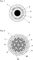
- a power cable 1 of an in-wheel motor includes a conductor portion 2, an insulator 3 configured to cover the outer circumference of the conductor portion 2, a hollow shield wire 4 configured to cover the outer circumference of the insulator 3, and a sheath 5 configured to cover the outer circumference of the shield wire 4, so as to be arranged in order, respectively, from the center portion.
- the conductor portion 2 is a composite strand obtained by stranding a plurality of wire strands 7 each of which is a strand of a plurality of filaments 6 having no insulating layer.
- the filament 6 is a tin-plated soft copper wire.
- the insulator 3 is a soft fluororesin having excellent flexibility.
- the shield wire 4 is a braided copper-foiled yarn cable having excellent flexibility, pliability, and light weight.
- the sheath 5 is composed of a soft fluororesin or polyester elastomer.
- a tensile member (tensile wire) 8 that bears tensile force acting on the power cable 1 is disposed at the center of the conductor portion 2.
- the tensile member 8 is preferably made of flexible material having high tensile strength, for example, KEVLAR (registered trademark) or the like.
- the composite strand that constitutes the conductor portion 2 is a composite strand having a double layered structure including an inner composite strand 2A and outer composite strand 2B, where the wire strands 7 are stranded in the inner composite strand 2A so as to form circular arrangement around the outer circumference of the tensile member 8; and the wire strands 7 are stranded in the outer composite strand 2B so as to form circular arrangement around the outer circumference of the inner composite strand 2A.
- the conductor portion 2 is formed from the composite strand obtained by stranding the plurality of wire strands 7 each of which is a strand of a plurality of filaments 6, the power cable is bent more easily than the case of using wire strands 7 having insulating layer. As a result, it is possible to assure small minimum bending radius while assuring a sufficient cross-sectional area of the conductor portion in order to allow large current required for a power cable used in an in-wheel motor to pass therethrought. Where the conductor portion 2 is a composite strand having a double layered structure as illustrated in the drawings, bending resistance is more excellent.
- the power cable has excellent bending resistance also because the filament 6 is a tin-plated soft copper wire, the insulator 3 is a soft fluororesin, and the shield wire 4 is a braided copper-foiled yarn cable.
- the material of the sheath 5 is a soft fluororesin or polyester elastomer. Since the soft fluororesin and the polyester elastomer have excellent flexibility, the power cable 1 has excellent bending resistance and twisting resistance by the use of these materials in the sheath 5.
- the in-wheel motor power cable 1 is expected to be used in a condition in which tensile stress is applied to the conductor portion 2. Even under such operation condition, presence of the tensile member 8 such as KEVLER (registered trademark) prevents breakage of the power cable due to the tensile force.
- KEVLER registered trademark
- Fig. 6 is a plan view of a cable bending test machine and Fig. 7 is a side view thereof.
- a fixed cable attachment 43 is mounted to a horizontal bar 42 disposed to the right side of a test machine frame 41.
- a slider 45 is disposed to the left side of the test machine frame 41 so as to be movable in the vertical direction.
- a movable cable attachment 44 is fixed to the slider 45.
- the slider 45 is moved reciprocally upward and downward by a vertical driving unit 46, and the movable cable attachment 44 moves in the movement direction Z upward and downward between positions A and C about a center position set at a position B.
- the vertical driving unit 46 includes an electric motor and a linear motion mechanism or a fluid pressure cylinder unit or the like.
- Both ends of the power cable 1 to be tested are fixed to both the cable attachments 43 and 44, respectively.
- a horizontal distance x in the right-left direction between the fixing position at the fixed cable attachment 43 and a fixing position on the movable is 350 mm, and a horizontal distance y as a front-rear offset amount is 100 mm.
- a coordinate of the slider 45 is set at zero when a fixing position of the power cable 1 at the fixed cable attachment 43 and a fixing position of the power cable 1 at the movable cable attachment 44 are at the same height
- the slider 45 moves by a stroke of about ⁇ 80 mm.
- the slider is moved by an operation frequency of 2Hz, and the power cable is evaluated after bending of one million times.
- respective (three) power cables 1 of a three-phase cable for motor driving are tested simultaneously, and damage to each of the power cables 1 is examined to evaluate its quality.
- Mode 2 In a case where the electric cable according to mode 1 is assumed to be used in such a condition that tensile stress is applied to the conductor portion, a material (in Table 1, referred to as "center member") such as KEVLAR (registered trademark) having high tensile strength is more preferably disposed at the center of the conductor portion.
- a material in Table 1, referred to as "center member” such as KEVLAR (registered trademark) having high tensile strength is more preferably disposed at the center of the conductor portion.
- the conductor portion is more preferably structured as a double layered composite strand as shown in Fig. 2 that includes the inner-side composite strand 2A and the outer-side composite strand 2B constituting an outer layer, where each of the inner-side composite strand 2A and the outer-side composite strand 2B is a strand of a plurality of wire strands 7 each of which is a strand of a plurality of filaments 6.
- the sheath is more preferably a soft fluororesin, polyester elastomer, or the like having excellent flexibility so as to ensure bending resistance, twisting resistance, and the like.
- a selection method for an in-wheel motor power cable that is, a method for selecting an electric cable used as an in-wheel motor power cable from electric cables is a method for selecting a cable that is designed to satisfy all the requirements described below in the present embodiment.
- the in-wheel motor power cable that satisfies these requirements (a) to (d) is selected, that is, when the above-described selection method is used, it is possible to obtain a power cable having a sufficient cross sectional area of a conductor portion to allow large current to pass therethrough while avoiding excessively large maximum diameter. Therefore, it is possible to avoid failure such as breakage of a cable in a long term operation even when bending is frequently applied. In addition, such a power cable can be obtained at low cost while avoiding a special processing during the production process. Further, by the above-described criteria for selection, it is possible to clarify a specific configuration of a power cable appropriate for an in-wheel motor.
- a wiring structure for an in-wheel motor power cable includes: an in-wheel motor driving unit 22 that is disposed in a wheel 21 (tire wheel assembly) and drives the wheel 21; and a suspension unit 24 that connects the in-wheel motor driving unit 22 to a vehicle body 23 in a manner capable of steering the in-wheel motor driving unit 22 about a steering axis extending in an vertical direction and capable of absorbing vertical vibration.
- This wiring structure further includes three bendable power cables 1 one end of each of which is connected to a power wire connection portion 25 disposed in the in-wheel motor driving unit 22, and the other end of each of which extends to the vehicle body 23 to supply power from the vehicle body 23 to the in-wheel motor driving unit 22.
- These power cables are the in-wheel motor power cables 1 according to the above-described embodiment described with reference to Fig. 1 or Fig. 2 .
- the steering axis K fundamentally extends in the vertical direction, the steering axis K may be slightly tilted toward the transverse direction (width direction) and/or the longitudinal direction (front-rear direction) of a vehicle.
- the in-wheel motor driving unit 22 is formed by integrally assembling: a wheel bearing 27 that supports the wheel assembly 21 with respect to an axle 26 such that the wheel assembly 21 is rotatable; an electric motor 28; and a reducer 29 that reduces a speed of rotation of the electric motor 28 and transmits the rotation to a rotating ring (not shown) of the wheel bearing 27.
- the axle 26 is a fixed shaft
- the rotating ring of the wheel bearing 27 is an outer ring.
- a wheel W of the wheel assembly 21 is mounted to the outer ring.
- the wheel assembly 21 includes the wheel W and a tire T.
- the electric motor 28 is a three-phase AC motor such as a synchronous motor or an induction motor.
- the suspension unit 24 is a strut-type suspension unit, and includes a lower arm 31 that extends in the transverse direction of a vehicle (hereafter, referred to as transverse direction), and a strut 32 that is disposed upper than the lower arm 31 and extends in the up-down direction.
- the strut 32 is disposed inward compared to the wheel assembly 21 and the in-wheel motor driving unit 22.
- the lower end of the strut 32 is joined to the in-wheel motor driving unit 22 and the upper end of the strut 32 is connected to the vehicle body 23 in a portion upper than the wheel assembly 21.
- the upper portion of the wheel assembly 21 and the upper portion of the in-wheel motor driving unit 22 are housed in a wheel housing 23a formed on the outer side of the vehicle body 23 in the transverse direction.
- the strut 32 is a suspension member that has a shock absorber 33 incorporated in the upper end region, and is extendable in the up-down direction.
- a coil spring 34 indicated by an alternate long and short dash line in the drawing is disposed around the outer circumference of the shock absorber 33.
- the in-wheel motor driving unit 22 is supported by the shock absorber 33 and the coil spring 34 so as to absorb vibration in the vertical direction.
- the lower arm 31 is a suspension disposed below an axis O of the in-wheel motor driving unit 22, and is connected to the in-wheel motor driving unit 22 through a ball joint (not shown) at an outer end 31a ( Fig. 4 ) in the transverse direction, and is connected to the vehicle body 23 through a vehicle body side member (not shown) at two inner ends 31b and 31c in the transverse direction.
- the lower arm 31 can oscillate in the vertical direction, where the inner ends 31b and 31c in transverse direction act as proximal ends and the outer end 31a in transverse direction act as a free end.
- a tie rod 35 is disposed upward of the lower arm 31.
- the tie rod 35 extends in the transverse direction, and the outer end thereof in the transverse direction is rotatably connected to the in-wheel motor driving unit 22.
- the inner end of the tie rod 35 in the transverse direction is connected to a not-illustrated steering device.
- the steering device advances and retracts the tie rod 35 in the transverse direction, and turns both the wheel assembly 21 and the in-wheel motor driving unit 22 about the steering axis K.
- the power cable 1 is connected as follows.
- a power cable terminal box 36 is disposed at the upper portion of the in-wheel motor driving unit 22, and the three power wire connection portions 25 are disposed in the power cable terminal box 36, where the power wire connection portions 25 are connected to internal wiring (not shown) of respective phases of the electric motor 28.
- the motor side ends of the power cables 1 are connected to the power wire connection portions 25, respectively.
- the ends of the three power cables 1 in the vehicle body side are collectively clamped by a clamp member 38 disposed in the vehicle body 23 through a bracket 37, and an end portion beyond the clamped portion is connected to a motor power supply (not shown) on the vehicle body 23.
- the clamp member 38 is, for example, positioned above the axis O of the in-wheel motor driving unit 22 so as to be adjacent to the inner side, in the transverse direction, of the lower end of the wheel housing 23a.
- the position of the motor side end of the power cable 1, that is, the position of the power wire connection portion 25 of the in-wheel motor driving unit 22 is changed due to the rotation of the in-wheel motor driving unit 22 about the steering axis K in the time of steering.
- the position of the motor side end of the power cable 1 is changed by the suspension unit 24 absorbing the upward-downward movement of the in-wheel motor driving unit 22.
- each power cable 1 in the motor side is repeatedly changed by the operation due to steering and the vertical movement of the in-wheel motor driving unit 22.
- the power cable 1 according to the above-described embodiment is used, or a power cable selected in the selection method for an in-wheel motor power cable according to the above-described embodiment is used, failure such as breakage of a cable in a long term operation can be avoided.
Landscapes
- Engineering & Computer Science (AREA)
- Chemical & Material Sciences (AREA)
- Combustion & Propulsion (AREA)
- Transportation (AREA)
- Mechanical Engineering (AREA)
- Physics & Mathematics (AREA)
- Spectroscopy & Molecular Physics (AREA)
- Manufacturing & Machinery (AREA)
- Insulated Conductors (AREA)
- Arrangement Or Mounting Of Propulsion Units For Vehicles (AREA)
Abstract
Description
- This application is based on and claims Convention priority to Japanese patent application No.
2016-204298, filed October 18, 2016 - The present invention relates to an in-wheel motor power cable used as a power cable of an in-wheel motor, a wiring structure for an in-wheel motor power cable, and a method of selecting an in-wheel motor power cable.
- The following constructions have been proposed for electric cables used in a section to which vibration of an automobile and/or bending are frequently applied.
- For example,
Patent Document 1 proposed an electric cable of enhanced mechanical strength and flexibility by a consruction as shown inFig. 8 . In this case, anelectric cable 10 is constituted of a strand of a plurality ofelectric wires 11 covered by asheath 12, where each of theelectric wires 11 is constituted by stranding (twisting) a plurality of conductor wires around a high tensile strength wire, and forming an insulating layer around the stranded conductor wires. -
Patent Document 2 proposed an electric cable as shown inFig. 9 . In this case, the electric cable includes a plurality ofelectric wires 11 each having a conductor and an insulating layer, aholding member 12, and asheath 13 that covers an outer circumference of theholding member 12, where grooves are formed in the surface of the insulating layer along the longitudinal direction of the electric wire, and the plurality of electric wires move relative to each other in the time of bending the electric cable. -
- Patent Document 1:
JP Laid-open Patent Publication No. 2007-305479 - Patent Document 2:
JP Patent No. 4984626 - Both
Patent Documents Patent Document - A power cable used for an in-wheel motor must have a sufficient cross-sectional area of a conductor portion so as to allow large electric current to pass therethrough. Where a plurality of conductors are covered by insulating layers as disclosed in
Patent Document Patent Document 1, each of the stranded wires has a tensile wire of high tensile strength. In the cable proposed inPatent Document 2, the insulating layers are provided with grooves. Both of these cases require specific processing during the production process of the cable, which may result in expensive cost for cables. - An object of the present invention is to provide an in-wheel motor power cable, a wiring structure for the in-wheel motor power cable, and a selection method for the in-wheel motor power cable, wherein the power cable has a sufficient cross-sectional area of a conductor portion for allowing large current to pass therethrough while avoiding excessively large maximum diameter, avoids failure such as breakage of the cable for a long term operation even under frequently bent conditions, and can be obtained at low cost while avoiding special processing.
- An in-wheel motor power cable according to one constitution of the present invention is a power cable through which power is supplied to an in-wheel motor, and includes: a conductor portion; an insulator configured to cover (surrounds) an outer circumference of the conductor portion; a hollow shield wire (tubular shield wire) configured to cover an outer circumference of the insulator; and a sheath configured to cover an outer circumference of the shield wire, wherein the conductor portion includes a composite strand that is a strand of a plurality of insulating-layer-free wire strands each of which is a strand of a plurality of filaments, the filaments are tin-plated soft copper (annealed copper) wires, the insulator is a soft fluorinated resin, and the shield wire is a braided copper-foiled yarn cable.
- In this configuration, even though the conductor portion is a composite strand, it is possible to avoid large maximum diameter of the cable since the wire strands used in the conductor portion do not include insulating layers. Further, since the conductor portion includes a composite strand that is a strand of a plurality of insulating-layer-free wire strands each of which is a strand of a plurality of filaments, the cable can be bent more easily than a cable constituted of filaments with insulating layers. As a result, it is possible to ensure sufficiently small minimum bending radius while ensuring sufficient cross-sectional area of the conductor portion that allows large current required for a power cable used in an in-wheel motor to pass therethrough. Moreover, also because the filament is a tin-plated soft copper wire, the insulator is a soft fluororesin, and the shield wire is a braided copper-foiled yarn cable (braid cable made of copper-foiled yarns), the power cable has excellent bending resistance (resistance to bending). Therefore, the power cable is appropriate as an in-wheel motor power cable which is frequently subjected to vibration and bending. Since the in-wheel motor is required to generate large driving torque, large current passes through the cable. However, generation of radiation noise from the power cable (which is concerned in the case of passing large current through a power cable) is prevented by the shield wire disposed outside the conductor portion.
- 0010 Regarding a combination of a material and a structure of the conductor portion, it has been confirmed through a bending test that the above described material and the structure of the conductor portion and the material of the insulator provide excellent bending resistance.
- 0011 In the above-described in-wheel motor power cable, the conductor portion may have, at a center thereof, a tensile member or tensile force bearer which bears a tensile force that acts on the power cable. The tensile member is preferably made of flexible material having high tensile strength, for example, KEVLAR™ or the like. The in-wheel motor power cable is expected to be used in a condition in which tensile stress is applied to the conductor portion. Even under such operation condition, presence of the tensile member prevents breakage of the power cable due to the tensile force.
- 0012 In the in-wheel motor power cable, the composite strand may be a double layered composite strand. In this case, a part of the wire strands is stranded (twisted) to form an inner composite strand, and the other part of the wire strands is stranded to form an outer composite strand that is disposed around the outer circumference of the inner composite strand. Where the conductor portion is a double layered composite strand, the cable has further excellent bending resistance.
- 0013 In the above-described in-wheel motor power cable, the sheath may be a soft fluororesin or polyester elastomer. Since the soft fluororesin or polyester elastomer has excellent flexibility, use of these materials for the sheath provides a power cable of further excellent bending resistance and twisting resistance.
- A wiring structure for an in-wheel motor power cable according to another constitution of the present invention includes:
- an in-wheel motor driving unit that is disposed in a wheel to drive the wheel;
- a suspension unit that connects the in-wheel motor driving unit to a vehicle body in a manner capable of absorbing vertical vibration; and a bendable power cable one end of which is connected to a power wire connection portion disposed in the in-wheel motor driving unit, and the other end of which extends to the vehicle body to supply power from the vehicle body to the in-wheel motor driving unit, wherein the power cable is an in-wheel motor power cable having the above-described configuration.
- In the wiring structure, a power cable is frequently subjected to bending due to vertical vibration during running of a vehicle. As explained above, the in-wheel motor power cable of the above-described configuration can have a sufficient cross sectional area of a conductor portion to allow large current to pass therethrough while avoiding excessively large maximum diameter. Therefore, according to the above-described wiring structure, it is possible to avoid failure such as breakage of a cable in a long term operation even when bending is frequently applied. In addition, it is possible to obtain the wiring structure at low cost while avoiding a special processing during the production process.
- In the wiring structure for an in-wheel motor power cable, the suspension unit may have a configuration such that the in-wheel motor driving unit is connected to the vehicle body in steerable (turnable) manner about a steering axis extending in an vertical (up-down) direction. In the in-wheel motor driving unit that is connected to the vehicle body via the suspension unit for steering, degree of bending that acts on the power cable is increased, and the influence of bending is added to the influence of vertical vibration. Even under such harsh operation conditions, it is possible to avoid failure such as breakage of a cable by the use of the in-wheel motor power cable of the above-described configuration.
- A selection method of an in-wheel motor power cable according to still another constitution of the present invention is a method of selecting an electric cable to be used as an in-wheel motor power cable, the method comprising selecting a power cable that is designed to satisfy all of the following requirements:
- the power cable includes a conductor portion, an insulator configured to cover (surrounds) an outer circumference of the conductor portion, a hollow shield wire configured to cover an outer circumference of the insulator, and a sheath configured to cover an outer circumference of the shield;
- the conductor portion includes a composite strand that is a strand of a plurality of insulating-layer-free wire strands each of which is a strand of a plurality of filaments;
- each of the filaments is an tin-plated soft copper wire;
- the insulator is a soft fluororesin; and
- the shield wire is a braided copper-foiled yarn cable.
- As it is understood from the above-described explanation for the in-wheel motor power cable of the present invention, a power cable selected to satisfy the above-described requirements can have a sufficient cross sectional area of a conductor portion to allow large current to pass therethrough while avoiding excessively large maximum diameter. Therefore, it is possible to avoid failure such as breakage of a cable in a long term operation even when bending is frequently applied. In addition, such a power cable can be obtained at low cost while avoiding a special processing during the production process. Further, by the above-described criteria for selection, it is possible to clarify a specific configuration of a power cable appropriate for an in-wheel motor.
- The "designed electric cable" may be a robot cable. Among various robot cables having various specifications, limited robot cables have optimal specifications to be used in the in-wheel motor. By selecting a power cable that satisfies the above-described requirements, a robot cable having appropriate specification for the in-wheel motor is selected.
- Any combination of at least two constructions, disclosed in the appended claims and/or the specification and/or the accompanying drawings should be construed as included within the scope of the present invention. In particular, any combination of two or more of the appended claims should be equally construed as included within the scope of the present invention.
- In any event, the present invention will become more clearly understood from the following description of preferred embodiments thereof, when taken in conjunction with the accompanying drawings. However, the embodiments and the drawings are given only for the purpose of illustration and explanation, and are not to be taken as limiting the scope of the present invention in any way whatsoever, which scope is to be determined by the appended claims. In the accompanying drawings, like reference numerals are used to denote like parts throughout the several views, and:
-
Fig. 1 is a cross-sectional view of a conceptual structure for an in-wheel motor power cable according to one embodiment of the present invention; -
Fig. 2 is a cross-sectional view of a specific example of the in-wheel motor power cable shown inFig. 1 ; -
Fig. 3 is a side view of a wiring structure for an in-wheel motor power cable as viewed from the front side of a vehicle, where the in-wheel motor power cable shown inFig. 1 is used; -
Fig. 4 is a front view of the wiring structure for the in-wheel motor power cable shown inFig. 1 as viewed from the inner side in the transverse direction of a vehicle; -
Fig. 5 is a plan view of the wiring structure for the in-wheel motor power cable shown inFig. 1 ; -
Fig. 6 is a plan view of a bending test machine; -
Fig. 7 is a front view of the bending test machine; -
Fig. 8 is a cross-sectional view of an example of a conventional power cable; and -
Fig. 9 is a cross-sectional view of another example of a conventional power cable. - A first embodiment of the present invention will be described with reference to the drawings. As shown in a cross-sectional view of
Fig. 1 , apower cable 1 of an in-wheel motor includes aconductor portion 2, aninsulator 3 configured to cover the outer circumference of theconductor portion 2, ahollow shield wire 4 configured to cover the outer circumference of theinsulator 3, and asheath 5 configured to cover the outer circumference of theshield wire 4, so as to be arranged in order, respectively, from the center portion. - As shown in
Fig. 2 , theconductor portion 2 is a composite strand obtained by stranding a plurality ofwire strands 7 each of which is a strand of a plurality offilaments 6 having no insulating layer. Thefilament 6 is a tin-plated soft copper wire. Theinsulator 3 is a soft fluororesin having excellent flexibility. Theshield wire 4 is a braided copper-foiled yarn cable having excellent flexibility, pliability, and light weight. Thesheath 5 is composed of a soft fluororesin or polyester elastomer. - A tensile member (tensile wire) 8 that bears tensile force acting on the
power cable 1 is disposed at the center of theconductor portion 2. Thetensile member 8 is preferably made of flexible material having high tensile strength, for example, KEVLAR (registered trademark) or the like. - More specifically, the composite strand that constitutes the
conductor portion 2 is a composite strand having a double layered structure including an innercomposite strand 2A and outercomposite strand 2B, where thewire strands 7 are stranded in the innercomposite strand 2A so as to form circular arrangement around the outer circumference of thetensile member 8; and thewire strands 7 are stranded in the outercomposite strand 2B so as to form circular arrangement around the outer circumference of the innercomposite strand 2A. - In the
power cable 1 having the above-described configuration, since thewire strands 7 having no insulating layer is used in theconductor portion 2, it is possible to avoid excessively large maximum diameter of the cable while using a composite strand. Therefore, also because theconductor portion 2 is formed from the composite strand obtained by stranding the plurality ofwire strands 7 each of which is a strand of a plurality offilaments 6, the power cable is bent more easily than the case of usingwire strands 7 having insulating layer. As a result, it is possible to assure small minimum bending radius while assuring a sufficient cross-sectional area of the conductor portion in order to allow large current required for a power cable used in an in-wheel motor to pass therethrought. Where theconductor portion 2 is a composite strand having a double layered structure as illustrated in the drawings, bending resistance is more excellent. - Further, the power cable has excellent bending resistance also because the
filament 6 is a tin-plated soft copper wire, theinsulator 3 is a soft fluororesin, and theshield wire 4 is a braided copper-foiled yarn cable. The material of thesheath 5 is a soft fluororesin or polyester elastomer. Since the soft fluororesin and the polyester elastomer have excellent flexibility, thepower cable 1 has excellent bending resistance and twisting resistance by the use of these materials in thesheath 5. - Since the in-wheel motor is required to generate large driving torque, large current passes through the
power cable 1. However, generation of radiation noise from the power cable 1 (which is concerned in the case of passing large current through a power cable) is prevented since theshield wire 4 is disposed outside theconductor portion 2. - The in-wheel
motor power cable 1 is expected to be used in a condition in which tensile stress is applied to theconductor portion 2. Even under such operation condition, presence of thetensile member 8 such as KEVLER (registered trademark) prevents breakage of the power cable due to the tensile force. - These effects were confirmed also by the following test.
- Next, a test performed for evaluating applicability of a power cable to an in-wheel motor will be described.
- A schematic construction of a test machine and an outline of the test will be described with reference to
Fig. 6 and Fig. 7. Fig. 6 is a plan view of a cable bending test machine andFig. 7 is a side view thereof. A fixedcable attachment 43 is mounted to ahorizontal bar 42 disposed to the right side of atest machine frame 41. Aslider 45 is disposed to the left side of thetest machine frame 41 so as to be movable in the vertical direction. Amovable cable attachment 44 is fixed to theslider 45. Theslider 45 is moved reciprocally upward and downward by avertical driving unit 46, and themovable cable attachment 44 moves in the movement direction Z upward and downward between positions A and C about a center position set at a position B. Thevertical driving unit 46 includes an electric motor and a linear motion mechanism or a fluid pressure cylinder unit or the like. - Both ends of the
power cable 1 to be tested are fixed to both thecable attachments cable attachment 43 and a fixing position on the movable is 350 mm, and a horizontal distance y as a front-rear offset amount is 100 mm. - Where a coordinate of the
slider 45 is set at zero when a fixing position of thepower cable 1 at the fixedcable attachment 43 and a fixing position of thepower cable 1 at themovable cable attachment 44 are at the same height, theslider 45 moves by a stroke of about ±80 mm. The slider is moved by an operation frequency of 2Hz, and the power cable is evaluated after bending of one million times. In this test, respective (three)power cables 1 of a three-phase cable for motor driving are tested simultaneously, and damage to each of thepower cables 1 is examined to evaluate its quality. - The criteria are as follows.
- (a) The evaluation is "acceptable" where all the filaments in the center conductor and the shield wire are not broken.
- (b) The evaluation is "applicable (there is a place of applicability)" where both of the center conductor and the shield wire show breakage of filaments, but the breakage rate for each of the center conductor and the shield wire is not greater than 10%.
- (c) The evaluation is "not acceptable" where at least one of the center conductor and the shield wire show breakage of filaments with breakage rate of not less than 10%.
- For the
power cables 1 of examples 1 to 2 and comparative examples 1 to 5 for which the test was performed, specifications and the test result of each of thepower cables 1 are summarized in Table 1. - As indicated in this table, the results were "acceptable" for Examples1 and 2, "applicable" for Comparative Examples 1, 3, and 4, and "not acceptable" for Comparative Examples 2 and 5.
[Table 1] Simple bending test result Example 1 Example 2 Comp. Ex. 1 Comp. Ex. 2 Comp. Ex. 3 Comp. Ex. 4 Comp. Ex. 5 Conductor portion Filament material tin-plated soft copper wire tin-plated soft copper wire tin-plated copper alloy wire anealed copper wire copper alloy wire tin-plated anealed copper wire tin-plated anealed copper wire Conductor wire structure composite strand (double) composite strand (double) composite strand composite strand composite strand (double) composite strand (double) composite strand Center member Non KEVLAR (registered trademark) Non Non Non Non Non Insulator Material soft fluororesin soft fluororesin fluorine-based resin crosslinked polyethylene crosslinked polyethylene silicone rubber silicone rubber Shield wire Material Braid of copper-foiled yarn Braid of copper-foiled yarn tin-plated copper alloy wire tin-plated anealed copper wire copper alloy wire braid of tin-plated anealed copper wire braid of tin-plated anealed copper wire Sheath Material soft fluororesin polyester elastomer thermoplastic polyurethane crosslinked polyethylene crosslinked polyethylene thermoplastic polyurethane thermoplastic polyurethane Simple bending test acceptable acceptable may be applicable not acceptable may be applicable may be applicable not acceptable - The above-described results indicate that a power cable according to
mode 1 that includes the following combination of (a) to (d) is appropriate in order to meet the requirements for the in-wheel motor power cable. Furthermore, it is indicated that the followingmodes 2 to 4 are more appropriate. - Mode 1:
- (a) The material of wires in the conductor portion is preferably a tin-plated soft copper wire.
- (b) The conductor portion is preferably structured as a composite strand obtained by stranding a plurality of wire strands each of which is a strand of filaments.
- (c) The insulator configured to cover the conductor portion is preferably a soft fluororesin having excellent flexibility.
- (d) The shield wire is preferably a braid cable made of copper-foiled yarns (obtained by winding a copper foil around a core yarns) that has excellent flexibility, pliability, and light weight.
- Mode 2: In a case where the electric cable according to
mode 1 is assumed to be used in such a condition that tensile stress is applied to the conductor portion, a material (in Table 1, referred to as "center member") such as KEVLAR (registered trademark) having high tensile strength is more preferably disposed at the center of the conductor portion. - Mode 3: In the cable according to
mode 1 ormode 2, the conductor portion is more preferably structured as a double layered composite strand as shown inFig. 2 that includes the inner-side composite strand 2A and the outer-sidecomposite strand 2B constituting an outer layer, where each of the inner-side composite strand 2A and the outer-sidecomposite strand 2B is a strand of a plurality ofwire strands 7 each of which is a strand of a plurality offilaments 6. - Mode 4: The sheath is more preferably a soft fluororesin, polyester elastomer, or the like having excellent flexibility so as to ensure bending resistance, twisting resistance, and the like.
- Based on the test results described above, a selection method for an in-wheel motor power cable, that is, a method for selecting an electric cable used as an in-wheel motor power cable from electric cables is a method for selecting a cable that is designed to satisfy all the requirements described below in the present embodiment.
- (a) The power cable includes a
conductor portion 2, aninsulator 3 configured to cover an outer circumference of theconductor portion 2, a hollow shield wire configured to cover an outer circumference of theinsulator 3, and asheath 5 configured to cover an outer circumference of the shield. - (b) The
conductor portion 2 includes a composite strand that is a strand of a plurality of insulating-layer-free wire strands 7 each of which is a strand of a plurality offilaments 6; - (c) Each of the
filaments 6 is a tin-plated soft copper wire; - (d) The
insulator 3 is a soft fluororesin; and theshield wire 4 is a braided copper-foiled yarn cable. - When the in-wheel motor power cable that satisfies these requirements (a) to (d) is selected, that is, when the above-described selection method is used, it is possible to obtain a power cable having a sufficient cross sectional area of a conductor portion to allow large current to pass therethrough while avoiding excessively large maximum diameter. Therefore, it is possible to avoid failure such as breakage of a cable in a long term operation even when bending is frequently applied. In addition, such a power cable can be obtained at low cost while avoiding a special processing during the production process. Further, by the above-described criteria for selection, it is possible to clarify a specific configuration of a power cable appropriate for an in-wheel motor.
- Next, an example of a wiring structure for an in-wheel power cable in which the
power cable 1 according to the embodiments shown inFig. 1 and Fig. 2 is used will be described with reference toFig. 3 to Fig. 5 . A wiring structure for an in-wheel motor power cable includes: an in-wheelmotor driving unit 22 that is disposed in a wheel 21 (tire wheel assembly) and drives thewheel 21; and asuspension unit 24 that connects the in-wheelmotor driving unit 22 to avehicle body 23 in a manner capable of steering the in-wheelmotor driving unit 22 about a steering axis extending in an vertical direction and capable of absorbing vertical vibration. This wiring structure further includes threebendable power cables 1 one end of each of which is connected to a powerwire connection portion 25 disposed in the in-wheelmotor driving unit 22, and the other end of each of which extends to thevehicle body 23 to supply power from thevehicle body 23 to the in-wheelmotor driving unit 22. These power cables are the in-wheelmotor power cables 1 according to the above-described embodiment described with reference toFig. 1 or Fig. 2 . Although the steering axis K fundamentally extends in the vertical direction, the steering axis K may be slightly tilted toward the transverse direction (width direction) and/or the longitudinal direction (front-rear direction) of a vehicle. - The in-wheel
motor driving unit 22 is formed by integrally assembling: a wheel bearing 27 that supports thewheel assembly 21 with respect to anaxle 26 such that thewheel assembly 21 is rotatable; anelectric motor 28; and areducer 29 that reduces a speed of rotation of theelectric motor 28 and transmits the rotation to a rotating ring (not shown) of thewheel bearing 27. In this example, theaxle 26 is a fixed shaft, and the rotating ring of the wheel bearing 27 is an outer ring. A wheel W of thewheel assembly 21 is mounted to the outer ring. Thewheel assembly 21 includes the wheel W and a tire T. Theelectric motor 28 is a three-phase AC motor such as a synchronous motor or an induction motor. - The
suspension unit 24 is a strut-type suspension unit, and includes alower arm 31 that extends in the transverse direction of a vehicle (hereafter, referred to as transverse direction), and astrut 32 that is disposed upper than thelower arm 31 and extends in the up-down direction. In the transverse direction, thestrut 32 is disposed inward compared to thewheel assembly 21 and the in-wheelmotor driving unit 22. The lower end of thestrut 32 is joined to the in-wheelmotor driving unit 22 and the upper end of thestrut 32 is connected to thevehicle body 23 in a portion upper than thewheel assembly 21. The upper portion of thewheel assembly 21 and the upper portion of the in-wheelmotor driving unit 22 are housed in awheel housing 23a formed on the outer side of thevehicle body 23 in the transverse direction. - The
strut 32 is a suspension member that has ashock absorber 33 incorporated in the upper end region, and is extendable in the up-down direction. Acoil spring 34 indicated by an alternate long and short dash line in the drawing is disposed around the outer circumference of theshock absorber 33. The in-wheelmotor driving unit 22 is supported by theshock absorber 33 and thecoil spring 34 so as to absorb vibration in the vertical direction. - The
lower arm 31 is a suspension disposed below an axis O of the in-wheelmotor driving unit 22, and is connected to the in-wheelmotor driving unit 22 through a ball joint (not shown) at anouter end 31a (Fig. 4 ) in the transverse direction, and is connected to thevehicle body 23 through a vehicle body side member (not shown) at twoinner ends lower arm 31 can oscillate in the vertical direction, where the inner ends 31b and 31c in transverse direction act as proximal ends and theouter end 31a in transverse direction act as a free end. - A
tie rod 35 is disposed upward of thelower arm 31. Thetie rod 35 extends in the transverse direction, and the outer end thereof in the transverse direction is rotatably connected to the in-wheelmotor driving unit 22. The inner end of thetie rod 35 in the transverse direction is connected to a not-illustrated steering device. The steering device advances and retracts thetie rod 35 in the transverse direction, and turns both thewheel assembly 21 and the in-wheelmotor driving unit 22 about the steering axis K. - The
power cable 1 is connected as follows. A powercable terminal box 36 is disposed at the upper portion of the in-wheelmotor driving unit 22, and the three powerwire connection portions 25 are disposed in the powercable terminal box 36, where the powerwire connection portions 25 are connected to internal wiring (not shown) of respective phases of theelectric motor 28. The motor side ends of thepower cables 1 are connected to the powerwire connection portions 25, respectively. - The ends of the three
power cables 1 in the vehicle body side are collectively clamped by aclamp member 38 disposed in thevehicle body 23 through abracket 37, and an end portion beyond the clamped portion is connected to a motor power supply (not shown) on thevehicle body 23. Theclamp member 38 is, for example, positioned above the axis O of the in-wheelmotor driving unit 22 so as to be adjacent to the inner side, in the transverse direction, of the lower end of thewheel housing 23a. - The position of the motor side end of the
power cable 1, that is, the position of the powerwire connection portion 25 of the in-wheelmotor driving unit 22 is changed due to the rotation of the in-wheelmotor driving unit 22 about the steering axis K in the time of steering. The position of the motor side end of thepower cable 1 is changed by thesuspension unit 24 absorbing the upward-downward movement of the in-wheelmotor driving unit 22. - The position of the end of each
power cable 1 in the motor side is repeatedly changed by the operation due to steering and the vertical movement of the in-wheelmotor driving unit 22. Where thepower cable 1 according to the above-described embodiment is used, or a power cable selected in the selection method for an in-wheel motor power cable according to the above-described embodiment is used, failure such as breakage of a cable in a long term operation can be avoided. - Although the embodiments for carrying out the present invention have been described above on the basis of the embodiments, the embodiments disclosed herein are illustrative in all aspects and not restrictive. The scope of the present invention is indicated by the claims, rather than by the above description, and is intended to include any modifications within the scope and meaning equivalent to the claims.
-
- 1
- power cable
- 2
- conductor portion
- 3
- insulator
- 4
- shield wire
- 5
- sheath
- 6
- wire
- 7
- assembled strand
Claims (7)
- An in-wheel motor power cable through which power is supplied to an in-wheel motor, the power cable comprising:a conductor portion;an insulator configured to cover an outer circumference of the conductor portion;a hollow shield wire configured to cover an outer circumference of the insulator;and a sheath configured to cover an outer circumference of the shield wire,wherein the conductor portion comprises a composite strand that is a strand of a plurality of insulating-layer-free wire strands each of which is a strand of a plurality of filaments,the filaments are tin-plated soft copper wires,the insulator is a soft fluororesin, andthe shield wire is a braid copper-foiled-yarn cable.
- The in-wheel motor power cable as claimed in claim 1, wherein the conductor portion has, at a center thereof, a tensile member that bears a tensile force that acts on the power cable.
- The in-wheel motor power cable as claimed in claim 1 or claim 2, wherein the composite strand is a double layered composite strand that includes an inner composite strand and an outer composite strand disposed around the outer circumference of the inner composite strand, wherein the inner composite strand is a strand of a part of the wire strands, and the outer composite strand is a strand of the other part of the wire strands.
- The in-wheel motor power cable as claimed in any one of claims 1 to 3, wherein the sheath is a soft fluororesin or polyester elastomer.
- A wiring structure of an in-wheel motor power cable, comprising:an in-wheel motor driving unit that is disposed in a wheel and drives the wheel;a suspension unit that connects the in-wheel motor driving unit to a vehicle body in a manner capable of absorbing vertical vibration; anda bendable power cable one end of which is connected to a power wire connection portion disposed in the in-wheel motor driving unit, and the other end of which extends to the vehicle body to supply power from the vehicle body to the in-wheel motor driving unit,wherein the power cable is an in-wheel motor power cable as claimed in any one of claims 1 to 4.
- The wiring structure of an in-wheel motor power cable as claimed in claim 5, wherein the suspension unit connects the in-wheel motor driving unit to the vehicle body such that the in-wheel motor driving unit is steerable about a steering axis extending in a vertical direction.
- A method for selecting an electric cable to be used as an in-wheel motor power cable, the method comprising selecting a power cable that is designed to satisfy all of the following requirements:the power cable includes a conductor portion, an insulator configured to cover an outer circumference of the conductor portion, a hollow shield wire configured to cover an outer circumference of the insulator, and a sheath configured to cover an outer circumference of the shield;the conductor portion includes a composite strand that is a strand of a plurality of insulating-layer-free wire strands each of which is a strand of a plurality of filaments;each of the filaments is an tin-plated soft copper wire;the insulator is a soft fluororesin; andthe shield wire is a braided copper-foiled yarn cable.
Applications Claiming Priority (2)
| Application Number | Priority Date | Filing Date | Title |
|---|---|---|---|
| JP2016204298A JP6113348B1 (en) | 2016-10-18 | 2016-10-18 | Power cable for in-wheel motor and its wiring structure / selection method |
| PCT/JP2016/083140 WO2018073978A1 (en) | 2016-10-18 | 2016-11-08 | In-wheel motor power cable, and wiring structure and selection method therefor |
Publications (2)
| Publication Number | Publication Date |
|---|---|
| EP3531430A1 true EP3531430A1 (en) | 2019-08-28 |
| EP3531430A4 EP3531430A4 (en) | 2020-06-24 |
Family
ID=58666724
Family Applications (1)
| Application Number | Title | Priority Date | Filing Date |
|---|---|---|---|
| EP16919203.6A Pending EP3531430A4 (en) | 2016-10-18 | 2016-11-08 | In-wheel motor power cable, and wiring structure and selection method therefor |
Country Status (5)
| Country | Link |
|---|---|
| US (1) | US10553330B2 (en) |
| EP (1) | EP3531430A4 (en) |
| JP (2) | JP6113348B1 (en) |
| CN (1) | CN108369840B (en) |
| WO (1) | WO2018073978A1 (en) |
Families Citing this family (5)
| Publication number | Priority date | Publication date | Assignee | Title |
|---|---|---|---|---|
| JP2019006265A (en) * | 2017-06-26 | 2019-01-17 | Ntn株式会社 | Wiring structure of in-wheel motor power line |
| KR20200018834A (en) * | 2018-08-13 | 2020-02-21 | 현대모비스 주식회사 | Fixing device for cable |
| CN109494672A (en) * | 2018-11-26 | 2019-03-19 | 国网河南省电力公司新野县供电公司 | A kind of buried cable safety guard |
| EP3947047A4 (en) * | 2019-03-24 | 2022-12-14 | TVS Motor Company Limited | A vehicle with an electric prime mover |
| JP6876861B1 (en) * | 2020-11-18 | 2021-05-26 | 株式会社デルタプラス | Composite electric wire and manufacturing method of the composite electric wire |
Family Cites Families (21)
| Publication number | Priority date | Publication date | Assignee | Title |
|---|---|---|---|---|
| JPS4984626A (en) | 1972-12-20 | 1974-08-14 | ||
| JPH0325805A (en) | 1989-06-23 | 1991-02-04 | Norichika Takebe | Conductor for electric wire |
| JP2006096968A (en) * | 2004-09-03 | 2006-04-13 | Daikin Ind Ltd | Cable jacket material and cable jacket |
| JP4965131B2 (en) * | 2006-01-27 | 2012-07-04 | トヨタ自動車株式会社 | In-wheel motor |
| JP4984626B2 (en) | 2006-04-28 | 2012-07-25 | 日立電線株式会社 | Electric cable |
| JP2007305479A (en) | 2006-05-12 | 2007-11-22 | Hitachi Cable Ltd | Electric cable |
| JP2010114019A (en) * | 2008-11-10 | 2010-05-20 | Hitachi Cable Ltd | Cable |
| JP5458707B2 (en) * | 2009-07-08 | 2014-04-02 | 日立金属株式会社 | cable |
| JP5709569B2 (en) * | 2011-02-17 | 2015-04-30 | 矢崎総業株式会社 | Shielded cable |
| CN202373328U (en) * | 2011-11-04 | 2012-08-08 | 淮南文峰航天电缆有限公司 | Light flexible fluoroplastic double-colored insulated wire |
| JP5836554B2 (en) | 2013-08-30 | 2015-12-24 | 日星電気株式会社 | Power cable |
| JP6313610B2 (en) | 2014-02-27 | 2018-04-18 | Ntn株式会社 | CONNECTION STRUCTURE OF IN-WHEEL MOTOR DRIVE DEVICE AND DAMPER AND SUSPENSION DEVICE PROVIDED WITH THIS CONNECTION |
| JP2015187956A (en) * | 2014-03-27 | 2015-10-29 | 株式会社フジクラ | cable |
| JP6265069B2 (en) | 2014-07-04 | 2018-01-24 | 日立金属株式会社 | Electric cable mounting structure |
| CN204242654U (en) * | 2014-11-03 | 2015-04-01 | 江苏亨通电子线缆科技有限公司 | The extraordinary flexible power cable of new forms of energy |
| CN104376901B (en) * | 2014-12-03 | 2017-02-01 | 江苏诸利电气有限公司 | Aluminum conductor for automotive wiring |
| CN104733084A (en) * | 2015-03-17 | 2015-06-24 | 苏州科宝光电科技有限公司 | Intelligent welding robot cable |
| CN104867538B (en) * | 2015-04-02 | 2017-02-22 | 西安飞机工业(集团)亨通航空电子有限公司 | Cable with extremely small bending radius and preparation method of externally coating material thereof |
| JP6114331B2 (en) * | 2015-04-06 | 2017-04-12 | 矢崎総業株式会社 | Bending resistant wire and wire harness |
| US9691518B2 (en) * | 2015-06-03 | 2017-06-27 | Hitachi Metals, Ltd. | Medical cable |
| JP2017183166A (en) * | 2016-03-31 | 2017-10-05 | 株式会社オートネットワーク技術研究所 | Insulation wire |
-
2016
- 2016-10-18 JP JP2016204298A patent/JP6113348B1/en active Active
- 2016-11-08 CN CN201680041534.6A patent/CN108369840B/en active Active
- 2016-11-08 WO PCT/JP2016/083140 patent/WO2018073978A1/en unknown
- 2016-11-08 EP EP16919203.6A patent/EP3531430A4/en active Pending
-
2017
- 2017-03-14 JP JP2017048455A patent/JP2018065545A/en active Pending
-
2019
- 2019-04-12 US US16/383,077 patent/US10553330B2/en active Active
Also Published As
| Publication number | Publication date |
|---|---|
| JP6113348B1 (en) | 2017-04-12 |
| CN108369840A (en) | 2018-08-03 |
| WO2018073978A1 (en) | 2018-04-26 |
| CN108369840B (en) | 2021-09-24 |
| US20190237216A1 (en) | 2019-08-01 |
| EP3531430A4 (en) | 2020-06-24 |
| JP2018067412A (en) | 2018-04-26 |
| JP2018065545A (en) | 2018-04-26 |
| US10553330B2 (en) | 2020-02-04 |
Similar Documents
| Publication | Publication Date | Title |
|---|---|---|
| US10553330B2 (en) | In-wheel motor power cable, and wiring structure and selection method therefor | |
| US9449740B2 (en) | Electric cable | |
| KR101978699B1 (en) | Cable provided with braided shield | |
| US10207659B2 (en) | Flex-resistant shielded composite cable and wire harness | |
| JP6437510B2 (en) | Wire harness | |
| EP2819256A1 (en) | Electrical wire routing structure, and electrical wire with external cladding member | |
| CN109286108B (en) | Conductive wire and wire harness | |
| WO2018135348A1 (en) | Electromagnetic shielding component and wiring harness | |
| WO2018116807A1 (en) | High-voltage wire for vehicle, and wire harness | |
| CN107799209B (en) | High-voltage electric wire for vehicle and wire harness | |
| JP2019169441A (en) | Composite cable | |
| JP6044499B2 (en) | Electric cable | |
| JP2018133139A (en) | Protective member, high voltage cable for vehicle, and wire harness | |
| CN103370750B (en) | Shielded cable | |
| JP2018041714A (en) | Vehicular high-voltage power line and wire harness | |
| KR20190062105A (en) | Cable provided with braided shield | |
| CN110431642B (en) | Conductive wire | |
| JP2017010655A (en) | Composite cable for automobile | |
| JP2000090753A (en) | Coaxial cable | |
| JP2019102424A (en) | Cable with braided shield | |
| JP7294258B2 (en) | composite cable | |
| JP2007253678A (en) | Composite wiring material | |
| JP2019053958A (en) | Wire harness | |
| KR20230090233A (en) | Cable | |
| JP2009159777A (en) | Self-supporting type cable |
Legal Events
| Date | Code | Title | Description |
|---|---|---|---|
| STAA | Information on the status of an ep patent application or granted ep patent |
Free format text: STATUS: THE INTERNATIONAL PUBLICATION HAS BEEN MADE |
|
| PUAI | Public reference made under article 153(3) epc to a published international application that has entered the european phase |
Free format text: ORIGINAL CODE: 0009012 |
|
| STAA | Information on the status of an ep patent application or granted ep patent |
Free format text: STATUS: REQUEST FOR EXAMINATION WAS MADE |
|
| 17P | Request for examination filed |
Effective date: 20190418 |
|
| AK | Designated contracting states |
Kind code of ref document: A1 Designated state(s): AL AT BE BG CH CY CZ DE DK EE ES FI FR GB GR HR HU IE IS IT LI LT LU LV MC MK MT NL NO PL PT RO RS SE SI SK SM TR |
|
| AX | Request for extension of the european patent |
Extension state: BA ME |
|
| DAV | Request for validation of the european patent (deleted) | ||
| DAX | Request for extension of the european patent (deleted) | ||
| A4 | Supplementary search report drawn up and despatched |
Effective date: 20200528 |
|
| RIC1 | Information provided on ipc code assigned before grant |
Ipc: H01B 7/04 20060101AFI20200520BHEP Ipc: H01B 9/02 20060101ALI20200520BHEP Ipc: H01B 3/44 20060101ALI20200520BHEP Ipc: B60K 7/00 20060101ALI20200520BHEP Ipc: H01B 13/00 20060101ALI20200520BHEP |
|
| STAA | Information on the status of an ep patent application or granted ep patent |
Free format text: STATUS: EXAMINATION IS IN PROGRESS |
|
| 17Q | First examination report despatched |
Effective date: 20230406 |