EP3531223B1 - Procédé et d'évitement d'obstacle et aéronef - Google Patents
Procédé et d'évitement d'obstacle et aéronef Download PDFInfo
- Publication number
- EP3531223B1 EP3531223B1 EP17832183.2A EP17832183A EP3531223B1 EP 3531223 B1 EP3531223 B1 EP 3531223B1 EP 17832183 A EP17832183 A EP 17832183A EP 3531223 B1 EP3531223 B1 EP 3531223B1
- Authority
- EP
- European Patent Office
- Prior art keywords
- aerial vehicle
- movable object
- obstacle
- axis
- dodging
- Prior art date
- Legal status (The legal status is an assumption and is not a legal conclusion. Google has not performed a legal analysis and makes no representation as to the accuracy of the status listed.)
- Active
Links
- 238000000034 method Methods 0.000 title claims description 36
- 230000001133 acceleration Effects 0.000 claims description 151
- 238000004891 communication Methods 0.000 claims description 2
- 238000004364 calculation method Methods 0.000 description 11
- 238000010586 diagram Methods 0.000 description 5
- 238000004590 computer program Methods 0.000 description 4
- 238000005259 measurement Methods 0.000 description 3
- RZVHIXYEVGDQDX-UHFFFAOYSA-N 9,10-anthraquinone Chemical group C1=CC=C2C(=O)C3=CC=CC=C3C(=O)C2=C1 RZVHIXYEVGDQDX-UHFFFAOYSA-N 0.000 description 2
- 238000001514 detection method Methods 0.000 description 2
- 238000005516 engineering process Methods 0.000 description 2
- 230000005484 gravity Effects 0.000 description 2
- 238000010408 sweeping Methods 0.000 description 2
- 241000251468 Actinopterygii Species 0.000 description 1
- 238000004422 calculation algorithm Methods 0.000 description 1
- 238000013461 design Methods 0.000 description 1
- 238000012938 design process Methods 0.000 description 1
- 230000000694 effects Effects 0.000 description 1
- 230000006870 function Effects 0.000 description 1
- 230000010354 integration Effects 0.000 description 1
- 230000003287 optical effect Effects 0.000 description 1
- 238000012545 processing Methods 0.000 description 1
Images


Classifications
-
- G—PHYSICS
- G05—CONTROLLING; REGULATING
- G05D—SYSTEMS FOR CONTROLLING OR REGULATING NON-ELECTRIC VARIABLES
- G05D1/00—Control of position, course, altitude or attitude of land, water, air or space vehicles, e.g. using automatic pilots
- G05D1/10—Simultaneous control of position or course in three dimensions
- G05D1/101—Simultaneous control of position or course in three dimensions specially adapted for aircraft
- G05D1/102—Simultaneous control of position or course in three dimensions specially adapted for aircraft specially adapted for vertical take-off of aircraft
-
- G—PHYSICS
- G05—CONTROLLING; REGULATING
- G05D—SYSTEMS FOR CONTROLLING OR REGULATING NON-ELECTRIC VARIABLES
- G05D1/00—Control of position, course, altitude or attitude of land, water, air or space vehicles, e.g. using automatic pilots
- G05D1/10—Simultaneous control of position or course in three dimensions
- G05D1/101—Simultaneous control of position or course in three dimensions specially adapted for aircraft
-
- G—PHYSICS
- G05—CONTROLLING; REGULATING
- G05D—SYSTEMS FOR CONTROLLING OR REGULATING NON-ELECTRIC VARIABLES
- G05D1/00—Control of position, course, altitude or attitude of land, water, air or space vehicles, e.g. using automatic pilots
- G05D1/02—Control of position or course in two dimensions
- G05D1/021—Control of position or course in two dimensions specially adapted to land vehicles
-
- G—PHYSICS
- G08—SIGNALLING
- G08G—TRAFFIC CONTROL SYSTEMS
- G08G5/00—Traffic control systems for aircraft, e.g. air-traffic control [ATC]
-
- G—PHYSICS
- G08—SIGNALLING
- G08G—TRAFFIC CONTROL SYSTEMS
- G08G5/00—Traffic control systems for aircraft, e.g. air-traffic control [ATC]
- G08G5/0004—Transmission of traffic-related information to or from an aircraft
- G08G5/0013—Transmission of traffic-related information to or from an aircraft with a ground station
-
- G—PHYSICS
- G08—SIGNALLING
- G08G—TRAFFIC CONTROL SYSTEMS
- G08G5/00—Traffic control systems for aircraft, e.g. air-traffic control [ATC]
- G08G5/0017—Arrangements for implementing traffic-related aircraft activities, e.g. arrangements for generating, displaying, acquiring or managing traffic information
- G08G5/0021—Arrangements for implementing traffic-related aircraft activities, e.g. arrangements for generating, displaying, acquiring or managing traffic information located in the aircraft
-
- G—PHYSICS
- G08—SIGNALLING
- G08G—TRAFFIC CONTROL SYSTEMS
- G08G5/00—Traffic control systems for aircraft, e.g. air-traffic control [ATC]
- G08G5/0047—Navigation or guidance aids for a single aircraft
- G08G5/0069—Navigation or guidance aids for a single aircraft specially adapted for an unmanned aircraft
-
- G—PHYSICS
- G08—SIGNALLING
- G08G—TRAFFIC CONTROL SYSTEMS
- G08G5/00—Traffic control systems for aircraft, e.g. air-traffic control [ATC]
- G08G5/04—Anti-collision systems
- G08G5/045—Navigation or guidance aids, e.g. determination of anti-collision manoeuvers
-
- B—PERFORMING OPERATIONS; TRANSPORTING
- B64—AIRCRAFT; AVIATION; COSMONAUTICS
- B64U—UNMANNED AERIAL VEHICLES [UAV]; EQUIPMENT THEREFOR
- B64U10/00—Type of UAV
- B64U10/10—Rotorcrafts
- B64U10/13—Flying platforms
- B64U10/14—Flying platforms with four distinct rotor axes, e.g. quadcopters
-
- B—PERFORMING OPERATIONS; TRANSPORTING
- B64—AIRCRAFT; AVIATION; COSMONAUTICS
- B64U—UNMANNED AERIAL VEHICLES [UAV]; EQUIPMENT THEREFOR
- B64U2201/00—UAVs characterised by their flight controls
- B64U2201/10—UAVs characterised by their flight controls autonomous, i.e. by navigating independently from ground or air stations, e.g. by using inertial navigation systems [INS]
-
- B—PERFORMING OPERATIONS; TRANSPORTING
- B64—AIRCRAFT; AVIATION; COSMONAUTICS
- B64U—UNMANNED AERIAL VEHICLES [UAV]; EQUIPMENT THEREFOR
- B64U30/00—Means for producing lift; Empennages; Arrangements thereof
- B64U30/20—Rotors; Rotor supports
Definitions
- the present invention relates to the field of controlling, and in particular, to a method and an apparatus for dodging an obstacle, and an aerial vehicle.
- the movable object In a movement process of a movable object, the movable object may be damaged because the movable object cannot dodge an obstacle after hitting the obstacle.
- the movable object may be an unmanned aerial vehicle, a robot, an unmanned ship, a manned aerial vehicle, an automobile, or the like.
- the unmanned aerial vehicle In a flight process of an unmanned aerial vehicle, the unmanned aerial vehicle may be damaged because the unmanned aerial vehicle cannot dodge an obstacle in time after hitting the obstacle. In a serious case, the unmanned aerial vehicle may crash.
- An existing technology for avoiding an obstacle is based on an infrared sensor or a radar sensor.
- the existing technology identifies and avoids the obstacle by a processor performing complex algorithm.
- this manner has a relatively high requirement on a processor and an environment condition, and may not achieve a desirable effect for avoiding an obstacle.
- IROS IROS a method for dodging an obstacle is disclosed using force determination.
- Seung Y In Seung Y.
- the present invention provides a method and an apparatus for dodging an obstacle, and an aerial vehicle, so that a movable object can take effective dodging measures after hitting the obstacle.
- the present invention provides a method for dodging an obstacle, applied to a movable object according to claim 1.
- the determining, according to the acceleration information of the movable object, that the movable object collides includes:
- x axis is a moving direction of the movable object.
- the movable object is an aerial vehicle
- a positive direction of x axis is the flight direction of the aerial vehicle
- the acceleration information includes acceleration change rates of two or three directions.
- the obtaining acceleration information of the movable object includes: obtaining the acceleration information measured by an inertial measurement unit (IMU) built in the movable object.
- IMU inertial measurement unit
- the method further includes: recording a collision position of the movable object.
- the location includes geographical coordinates and a flight height.
- the method further includes: when the movable object moves towards the collision position of the movable object, and a distance between the movable object and the collision position of the movable object is less than a preset distance, moving, by the movable object, along the direction for dodging the obstacle.
- An embodiment of the present invention further provides an apparatus for dodging an obstacle, applied to a movable object.
- the apparatus includes:
- the acceleration information includes an acceleration change rate of at least one direction.
- the determining module is specifically configured to:
- the determining module is specifically configured to:
- x axis is a moving direction of the movable object.
- the movable object is an aerial vehicle
- a positive direction of x axis is the flight direction of the aerial vehicle
- the acceleration information includes acceleration change rates of two or three directions.
- the obtaining module is specifically configured to: obtain the acceleration information measured by an IMU built in the movable object.
- the apparatus further includes a recording module, and the recording module is configured to record a collision location of the movable object.
- the location includes geographical coordinates and a flight height.
- control module is further configured to: when the movable object moves towards the collision position of the movable object, and a distance between the movable object and the collision position of the movable object is less than a preset distance, control the movable object to move along the direction for dodging the obstacle.
- An embodiment of the present invention further provides an aerial vehicle according to claim 8.
- the processor is configured to:
- x axis is a moving direction of the aerial vehicle.
- a positive direction of x axis is a flight direction of the aerial vehicle.
- the acceleration information includes acceleration change rates of two or three directions.
- the processor is further configured to: record a collision location.
- the location includes geographical coordinates and a flight height.
- the processor is further configured to: when the aerial vehicle moves towards the collision position of the aerial vehicle, and a distance between the aerial vehicle and the collision position of the aerial vehicle is less than a preset distance, control the aerial vehicle to move along the direction for dodging the obstacle.
- An embodiment of the present invention further provides a movable object, including a processor and a computer readable storage medium, where the computer readable storage medium stores an instruction, and when the instruction is executed by the processor, the foregoing method for dodging an obstacle is implemented.
- An embodiment of the present invention further provides a computer readable storage medium, storing a computer program, where when the computer program is executed by a processor, the foregoing method for dodging an obstacle is implemented.
- the embodiments of the present invention include: obtaining the acceleration information of the movable object; determining, according to the acceleration information of the movable object, that the movable object collides; determining, according to the acceleration information, a direction for dodging an obstacle; and controlling the movable object to move along the direction for dodging the obstacle, to avoid the obstacle.
- collision of the movable object and a dodging direction can be accurately informed according to the acceleration information of the movable object, to effectively dodge the obstacle and avoid continuously hitting the obstacle.
- an IMU built in the movable object may be used as an apparatus for detecting the acceleration information, and no additional hardware needs to be added, to reduce hardware costs.
- the collision location of the movable object is recorded.
- the movable object moves towards the location and is relatively close to the location, the movable object moves along the direction for dodging the obstacle, to avoid collision, and further ensure safety of the movable object.
- Steps shown in flowcharts of the accompanying drawings may be performed, for example, in a computer system of a set of computer executable instructions.
- a logical sequence is shown in a flowchart, the shown or described steps may be performed in a different sequence in some cases.
- Embodiments of the present invention provide a method and an apparatus for dodging an obstacle.
- the method and the apparatus may be applied to a movable object, so that the movable object can identify a collision direction during collision, and the movable object is controlled to move in a direction opposite to the collision direction to avoid the obstacle in time.
- the movable object in the embodiments of the present invention may be an unmanned aerial vehicle, a manned aerial vehicle, an unmanned automobile, an unmanned ship, an intelligent robot (such as a floor sweeping robot or a floor mopping robot), and the like.
- the aerial vehicle 10 includes a vehicle body 11, an arm 12, an actuating apparatus 13, an Inertial Measurement Unit (IMU) 14, and a processor 15.
- IMU Inertial Measurement Unit
- the arm 12 is connected to the vehicle body 11, the actuating apparatus 13 is disposed on the arm 12, and the IMU 14 is in communication connection with the processor 15, and the IMU 14 is configured to obtain acceleration information of the aerial vehicle 10.
- the IMU 14 may be disposed within the vehicle body 11.
- the aerial vehicle 10 includes four arms 12, that is, the aerial vehicle in this embodiment is a quadrotor aerial vehicle.
- the aerial vehicle 10 may be a rotary aerial vehicle, a fixed wing aerial vehicle, or an aerial vehicle that combines a fixed wing and a rotary wing.
- the rotary aerial vehicle may have single rotor (one arm), two rotors (two arms), three rotors (three arms), six rotors (six arms), eight rotors (eight arms), or the like.
- the actuating apparatus 13 usually includes a motor disposed at the end of the arm 12 and a propeller connected to a shaft of the motor.
- the motor drives the propeller to rotate to provide a lift force for the movable object 10.
- the IMU 14 may measure a three-axis attitude angle (or an angular velocity) and an acceleration of the aerial vehicle 10, and is usually disposed at a position of a center of gravity of the aerial vehicle 10.
- one IMU 14 includes three single-axis accelerators and three single-axis gyroscopes.
- the three accelerators separately detect acceleration signals of the aerial vehicle 10 in three axes of three-dimensional space.
- the gyroscope detects an angular speed signal.
- the IMU 14 measures an angular speed and an acceleration of the aerial vehicle 10 in three-dimensional space, and calculates an attitude of the aerial vehicle 10 according to the angular speed and the acceleration of the aerial vehicle 10.
- the IMU 14 may be an IMU coming with the aerial vehicle 10.
- the IMU 14 may be an additionally added IMU chip, and the IMU chip may be fixed on the movable object 10 by means of a hard connection.
- the processor 15 may include multiple functional units, for example, a flight control unit configured to control a flight attitude of the aerial vehicle, a target identification unit configured to identify a target, a tracking unit configured to track a particular target, a navigation unit (for example, a GPS (Global Positioning System) or Beidou) configured to navigate the aerial vehicle, and a data processing unit configured to process environment information obtained by a related airborne device.
- a flight control unit configured to control a flight attitude of the aerial vehicle
- a target identification unit configured to identify a target
- a tracking unit configured to track a particular target
- a navigation unit for example, a GPS (Global Positioning System) or Beidou
- a data processing unit configured to process environment information obtained by a related airborne device.
- the processor 15 determines, by obtaining the acceleration information detected by the IMU 14, whether the aerial vehicle 10 collides.
- the acceleration information includes an acceleration change rate of at least one direction.
- an acceleration of the aerial vehicle 10 is in a process of slowly changing, as shown in FIG. 2 .
- the acceleration measured by the IMU 14 suddenly changes.
- a change degree of the acceleration may be represented by the acceleration change rate, but when the acceleration change rate is greater than an acceleration change threshold, the processor 15 determines that the aerial vehicle 10 collides.
- An example in which an acceleration in a direction of x axis suddenly changes is used.
- the processor 15 determines, according to the acceleration change rate in x axis, that the aerial vehicle 10 collides in a direction of x axis, and determines the direction for dodging the obstacle on this basis.
- the acceleration change rate threshold Ah may be set according to experience, and this is not specifically limited in the present invention.
- an acceleration change rate of the aerial vehicle may be determined by resolving a vector sum of the acceleration change rates in three directions, and a direction of the acceleration change rate is the direction for dodging the obstacle by the aerial vehicle 10.
- the direction for dodging the obstacle by the aerial vehicle in space may be determined according to the three angles.
- the processor 15 may further record a collision location of the aerial vehicle 10.
- the location includes geographical coordinates and a flight height.
- the processor 15 controls the aerial vehicle 10 to move along the direction for dodging the obstacle determined according to the foregoing method.
- the processor 15 is further configured to: send collision location information to a control device, so that makes the control device display the location information, inform an operator the geographical location, and prevent the operator from controlling the aerial vehicle to fly to the location to hit the obstacle again.
- the processor 15 is further configured to: when the aerial vehicle 10 moves towards the collision location, and a distance between the aerial vehicle and the collision location is less than the preset distance, control the actuating apparatus according to a preset rule or a control instruction, to avoid collision.
- the preset rule may be switching to fly in a direction such as below, above, or on the left or right of the collision location and away from the collision location by a specified distance, or staying at a current location and waiting for a subsequent control instruction and the like.
- the processor 15 is further configured to: when the aerial vehicle 10 moves towards the collision location, and a distance between the aerial vehicle and the collision location is less than the preset distance, send alert information to a control device.
- the processor 15 is configured to: when the aerial vehicle 10 moves towards the collision location, and a distance between the aerial vehicle and the collision location is less than the preset distance, send alert information to a control device, and receive a control instruction returned by the control device, to avoid collision again.
- collision of the aerial vehicle and an dodging direction can be accurately informed according to the acceleration information of the aerial vehicle, to effectively avoid an obstacle and avoid continuously hitting the obstacle.
- An IMU built in the aerial vehicle may be used as an apparatus for detecting the acceleration information, and no additional hardware needs to be added, to reduce hardware costs.
- the collision location of the aerial vehicle is recorded. When the aerial vehicle moves towards the location and is relatively close to the location, the aerial vehicle moves along the direction for dodging the obstacle, to avoid collision, and further ensure safety of the movable object.
- FIG. 5 is a flowchart of a method for dodging an obstacle according to an embodiment of the present invention. The method may be applied to a movable object, and the method includes the following steps.
- Step 101 Obtain acceleration information of the movable object.
- the movable object is an object that can move and a moving direction thereof can be controlled.
- an aerial vehicle that can fly or a vehicle that moves on the land.
- the aerial vehicle may be a rotary aerial vehicle, a fixed wing aerial vehicle, or an aerial vehicle that combines a fixed wing and a rotary wing.
- the rotary aerial vehicle may have single rotor, two rotors, three rotors, four rotors, six rotors, eight rotors, or the like.
- the aerial vehicle may include but is not limited to an unmanned aerial vehicle.
- the movable object may further be an unmanned automobile, a floor sweeping robot, a floor mopping robot, and the like.
- the acceleration information is obtained by a built in IMU.
- the IMU may measure a three-axis attitude angle (or an angular velocity) and an acceleration of the movable object, and is usually disposed at a position of a center of gravity of the movable object.
- one IMU includes three single-axis accelerators and three single-axis gyroscopes.
- the accelerator detects a three-axis acceleration signal of the movable object.
- the gyroscope detects an angular speed signal.
- the IMU measures an angular speed and an acceleration of the movable object in three-dimensional space, and calculates an attitude of the movable object according to the angular speed and the acceleration of the movable object.
- the IMU may be an IMU coming with the movable object, or may be an additionally added IMU chip, and the IMU chip may be fixed on the movable object by means of a hard connection.
- the acceleration information includes an acceleration change rate of at least one direction.
- X axis, y axis and z axis are perpendicular to each other, and the acceleration information may include an acceleration change rate of at least one of the three directions of x axis, y axis and z axis.
- the acceleration information includes acceleration change rates of two or three directions.
- the acceleration information may include acceleration change rates of the three directions of x axis, y axis and z axis, or may include acceleration change rates of any two of the three directions of x axis, y axis and z axis.
- Step 102 Determine, according to the acceleration information of the movable object, that the movable object collides.
- An example of three directions of x axis, y axis and z axis in three-dimensional space is used.
- an acceleration of the movable object is in a process of slowly changing, as shown in FIG. 2 .
- the acceleration change rate threshold is Ah. If it is found at the time point t1 that
- the acceleration change rate threshold Ah may be set in advance according to experience, and this is not specifically limited in the present invention.
- Step 103 Determine, according to the acceleration information, a direction for dodging an obstacle.
- an acceleration change rate of the movable object is determined according to a vector sum of the acceleration change rate of the at least one direction; and a direction of the acceleration change rate is determined as the direction for dodging the obstacle.
- x axis is a moving direction of the movable object
- y axis is obtained by rotating anticlockwise x axis by 90 degrees on a horizontal plane
- the sky is z axis. That is, x axis, y axis and z axis are perpendicular to each other.
- the direction for dodging the obstacle is determined according to the ⁇ , ⁇ and ⁇ .
- the movable object is an aerial vehicle
- a positive direction of x axis is a flight direction of the aerial vehicle
- a collision direction may further be determined according to the acceleration information, and a direction opposite to the collision direction is a dodging direction.
- a collision direction determined according to the acceleration information may be determined by using the acceleration change rate of the at least one direction, and is an opposite direction of the vector sum of the acceleration change rate.
- a calculation method is similar to that in the foregoing descriptions, and detailed descriptions are not provided herein again.
- Step 104 Control the movable object to move along the direction for dodging the obstacle, to avoid the obstacle.
- a processor of the movable object may control an actuating apparatus of the movable object to fly according to a dodging direction obtained by calculation, to avoid the obstacle.
- collision of the movable object and a dodging direction can be accurately informed according to the acceleration information of the movable object, to effectively avoid an obstacle and avoid continuously hitting the obstacle.
- an IMU built in the movable object may be used as an apparatus for detecting the acceleration information, and no additional hardware needs to be added, to reduce hardware costs.
- FIG. 6 is a flowchart of a method for dodging an obstacle according to another embodiment of the present invention. Steps 201 to 204 are the same as steps 101 to 104 in the above described embodiment, and details are not described herein again.
- Step 205 Record a collision position of the movable object.
- the location includes geographical coordinates and a flight height.
- step 205 may be performed after step 202, that is, a collision location is immediately recorded after it is determined that the movable object collides.
- collision location information may be sent to a control device, so that makes the control device display the location information, inform an operator the geographical location, and prevent the operator from controlling the movable object to move to the location to hit the obstacle again.
- Step 206 When the movable object moves towards the collision position of the movable object, and a distance between the movable object and the collision position of the movable object is less than a preset distance, the movable object moves along the direction for dodging the obstacle.
- the movable object by recording the collision location of the movable object, when the movable object moves towards the location and is relatively close to the location, the movable object moves along the direction for dodging the obstacle, which is capable of avoiding collision, and further ensure safety of the movable object.
- the movable object when the movable object moves towards the collision location, and a distance between the movable object and the collision location is less than a preset distance, the movable object moves according to a preset rule or a control instruction, to avoid collision.
- the preset rule may be controlling the movable object to fly in a direction such as below, above, or on the left or right of the collision location and away from the collision location by a specified distance, or staying at a current location and waiting for a subsequent control instruction and the like.
- the movable object when the movable object moves towards the collision location, and a distance between the movable object and the collision location is less than the preset distance, the movable object sends alert information to a control device.
- the movable object when the movable object moves towards the collision location, and a distance between the movable object and the collision location is less than the preset distance, the movable object sends alert information to a control device, and receives a control instruction returned by the control device, to avoid collision again.
- An embodiment of the present invention further provides an apparatus for dodging an obstacle.
- the apparatus is configured to implement the foregoing embodiments and implementations, and what has been described is not described in detail again.
- a term "module" may implement a combination of software and/or hardware having a preset function.
- the apparatus described in the following embodiments may be implemented by using software, implementation by using hardware or a combination of software and hardware is also possible and is conceived.
- the apparatus for dodging an obstacle in this embodiment of the present invention includes:
- the determining module 32 is specifically configured to:
- the determining module 32 is specifically configured to:
- x axis is a moving direction of the movable object.
- the movable object is an aerial vehicle
- a positive direction of x axis is the flight direction of the aerial vehicle
- the acceleration information includes acceleration change rates of two or three directions.
- the obtaining module 31 is specifically configured to: obtain the acceleration information measured by an IMU built in the movable object.
- the apparatus further includes a recording module 34, and the recording module 34 is configured to record a collision location of the movable object.
- the location includes geographical coordinates and a flight height.
- control module 33 is further configured to: when the movable object moves towards the collision position of the movable object, and a distance between the movable object and the collision position of the movable object is less than a preset distance, control the movable object to move along the direction for dodging the obstacle.
- the obtaining module 31 may be an inertial measurement chip
- the determining module 32 may be a processor
- the control module 33 may be a control chip such as a flight control chip.
- the recording module 34 may be a memory.
- collision of the movable object and a dodging direction can be accurately informed according to the acceleration information of the movable object, to effectively avoid an obstacle and avoid continuously hitting the obstacle.
- an IMU built in the movable object may be used as an apparatus for detecting the acceleration information, and no additional hardware needs to be added, to reduce hardware costs.
- the collision location of the movable object is recorded. When the movable object moves towards the location and is relatively close to the location, the movable object moves along the direction for dodging the obstacle, to avoid collision, which further ensures safety of the movable object.
- An embodiment of the present invention further provides a movable object, including a processor and a computer readable storage medium, where the computer readable storage medium stores an instruction, and when the instruction is executed by the processor, any of the foregoing methods for dodging an obstacle is implemented.
- An embodiment of the present invention further provides a computer readable storage medium, storing a computer program, where when the computer program is executed by a processor, any of the foregoing methods for dodging an obstacle is implemented.
- the computer readable storage medium may include but is not limited to: various mediums that can store program code such as a USB flash drive, a read-only memory (ROM), a random access memory (RAM), a removable hard disk, a magnetic disc, and an optical disc.
- program code such as a USB flash drive, a read-only memory (ROM), a random access memory (RAM), a removable hard disk, a magnetic disc, and an optical disc.
- the modules or the steps in the embodiments of the present invention may be implemented by using a general-purpose calculation apparatus.
- the modules or the steps may be integrated on a single calculation apparatus, or distributed on a network formed by multiple calculation apparatuses.
- the modules or the steps may be implemented by using program code that can be executed by a calculation apparatus. Therefore, the modules or the steps may be stored in a storage apparatus and is executed by a calculation apparatus.
- the steps shown or described may be performed in a sequence different from that herein, or may be separately produced as integrated circuit modules, or multiple modules or steps thereof are produced as a single integrated circuit module for implementation. Therefore, the embodiments of the present invention are not limited to any particular combination of hardware and software.
Landscapes
- Engineering & Computer Science (AREA)
- Aviation & Aerospace Engineering (AREA)
- Physics & Mathematics (AREA)
- General Physics & Mathematics (AREA)
- Radar, Positioning & Navigation (AREA)
- Remote Sensing (AREA)
- Automation & Control Theory (AREA)
- Computer Networks & Wireless Communication (AREA)
- Navigation (AREA)
- Traffic Control Systems (AREA)
Claims (14)
- Procédé d'évitement d'un, appliqué à un objet mobile, ledit procédé comprenant :
obstacle
l'acquisition d'informations d'accélération de l'objet mobile ;
la détermination, en fonction des informations d'accélération de l'objet mobile, que l'objet mobile subit une collision ;
la détermination, en fonction des informations d'accélération, d'une direction d'évitement d'un obstacle ; et
la commande de déplacement de l'objet mobile dans la direction d'évitement de l'obstacle, afin d'éviter l'obstacle,
caractérisé en ce que
les informations d'accélération comprennent un taux de variation d'accélération de trois directions,
où la détermination, en fonction des informations d'accélération, d'une direction d'évitement d'un obstacle comprend :la détermination d'un taux de variation d'accélération de l'objet mobile en fonction d'une somme vectorielle du taux de variation d'accélération des trois directions ; etla détermination d'une direction du taux de variation d'accélération en tant que direction d'évitement de l'obstacle. - Procédé selon la revendication 1, où la détermination, en fonction des informations d'accélération de l'objet mobile, que l'objet mobile subit une collision comprend :la détermination si le taux de variation d'accélération de ladite au moins une direction est supérieur à un seuil de taux de variation d'accélération ; et,si oui, la détermination que l'objet mobile subit une collision.
- Procédé selon la revendication 1, où la détermination d'une direction du taux de variation d'accélération en tant que direction d'évitement de l'obstacle comprend :
le calcul d'angles α, β et γ entre le taux de variation d'accélération de l'objet mobile et l'axe x, l'axe y et l'axe z dans un espace tridimensionnel :

 ΔAx, ΔAy et ΔAz sont les taux de variation d'accélération respectifs dans trois directions de l'axe x, l'axe y et l'axe z perpendiculairement les uns aux autres ; etla détermination, en fonction de α, β et γ, de la direction d'évitement de l'obstacle.
 - Procédé selon la revendication 3, où l'objet mobile est un aéronef, et une direction positive de l'axe x est une direction de vol de l'aéronef.
- Procédé selon l'une des revendications 1 à 4, ledit procédé comprenant en outre :
l'enregistrement d'un emplacement de collision de l'objet mobile. - Procédé selon la revendication 5, où l'emplacement comprend les coordonnées géographiques et une altitude de vol.
- Procédé selon la revendication 5 ou la revendication 6, ledit procédé comprenant en outre :
si l'objet mobile se déplace vers l'emplacement de collision de l'objet mobile, et une distance entre l'objet mobile et l'emplacement de collision de l'objet mobile est inférieure à une distance définie, le déplacement de l'objet mobile dans la direction d'évitement de l'obstacle. - Aéronef (10), comprenant :un corps d'aéronef (11) ;un bras (12) raccordé au corps d'aéronef (11) ;un dispositif d'actionnement (13) monté sur le bras (12) ;un processeur (15) ; etune IMU (14), en liaison de communication avec le processeur (15), et prévue pour acquérir des informations d'accélération de l'aéronef (10),le processeur (15) étant prévu pour :déterminer, en fonction des informations d'accélération de l'aéronef, que l'aéronef subit une collision ;déterminer, en fonction des informations d'accélération, une direction d'évitement d'un obstacle ; etcommander le déplacement de l'aéronef dans la direction d'évitement de l'obstacle, afin d'éviter l'obstacle,caractérisé en ce queles informations d'accélération comprennent un taux de variation d'accélération de trois directions, et le processeur (15) est prévu pour :déterminer un taux de variation d'accélération de l'aéronef (10) en fonction d'une somme vectorielle du taux de variation d'accélération des trois directions ; etdéterminer une direction du taux de variation d'accélération en tant que direction d'évitement de l'obstacle.
- Aéronef (10) selon la revendication 8, où le processeur (15) est prévu pour :déterminer si le taux de variation d'accélération de ladite au moins une direction est supérieur à un seuil de taux de variation d'accélération ; et,si oui, déterminer que l'aéronef (10) subit une collision.
- Aéronef (10) selon la revendication 9, où le processeur (15) est prévu pour calculer les angles α, β et γ entre le taux de variation d'accélération de l'aéronef (10) et l'axe x, l'axe y et l'axe z dans un espace tridimensionnel :

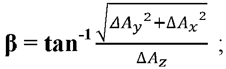
 ΔAx, ΔAy et ΔAz sont les taux de variation d'accélération respectifs dans trois directions de l'axe x, l'axe y et l'axe z perpendiculairement les uns aux autres ; etdéterminer, en fonction de α, β et γ, la direction d'évitement de l'obstacle.
 - Aéronef (10) selon la revendication 10, où une direction positive de l'axe x est une direction de vol de l'aéronef.
- Aéronef (10) selon l'une des revendications 8 à 11, où le processeur (15) est en outre prévu pour :
enregistrer un emplacement de collision. - Aéronef (10) selon la revendication 12, où
l'emplacement comprend les coordonnées géographiques et une altitude de vol. - Aéronef (10) selon la revendication 12 ou la revendication 13, où le processeur (15) est en outre prévu pour :
si l'aéronef (10) se déplace vers l'emplacement de collision de l'aéronef (10), et une distance entre l'aéronef (10) et l'emplacement de collision de l'aéronef (10) est inférieure à une distance définie, la commande de déplacement de l'aéronef (10) dans la direction d'évitement de l'obstacle.
Applications Claiming Priority (1)
| Application Number | Priority Date | Filing Date | Title |
|---|---|---|---|
| PCT/CN2017/118673 WO2019127029A1 (fr) | 2017-12-26 | 2017-12-26 | Procédé et dispositif d'évitement d'obstacle et aéronef |
Publications (3)
| Publication Number | Publication Date |
|---|---|
| EP3531223A4 EP3531223A4 (fr) | 2019-08-28 |
| EP3531223A1 EP3531223A1 (fr) | 2019-08-28 |
| EP3531223B1 true EP3531223B1 (fr) | 2020-05-27 |
Family
ID=62233590
Family Applications (1)
| Application Number | Title | Priority Date | Filing Date |
|---|---|---|---|
| EP17832183.2A Active EP3531223B1 (fr) | 2017-12-26 | 2017-12-26 | Procédé et d'évitement d'obstacle et aéronef |
Country Status (4)
| Country | Link |
|---|---|
| US (1) | US10725482B2 (fr) |
| EP (1) | EP3531223B1 (fr) |
| CN (1) | CN108124472B (fr) |
| WO (1) | WO2019127029A1 (fr) |
Families Citing this family (8)
| Publication number | Priority date | Publication date | Assignee | Title |
|---|---|---|---|---|
| AT16013U1 (de) * | 2017-04-28 | 2018-10-15 | Ars Electronica Linz Gmbh & Co Kg | Unbemanntes Luftfahrzeug mit einer modularen Schwarmsteuereinheit |
| WO2020037524A1 (fr) * | 2018-08-22 | 2020-02-27 | 深圳市大疆创新科技有限公司 | Procédé de commande pour plate-forme mobile, plate-forme mobile et support de stockage lisible |
| CN109381125B (zh) * | 2018-09-04 | 2021-08-10 | 广东美的厨房电器制造有限公司 | 扫地机器人及其控制系统及控制方法 |
| CN111107312A (zh) * | 2019-10-29 | 2020-05-05 | 韦玉伍 | 一种酒店客房的智能机器人自主巡检系统 |
| CN113039919B (zh) * | 2019-12-26 | 2022-06-10 | 南京泉峰科技有限公司 | 智能割草设备 |
| CN114368255B (zh) * | 2020-10-14 | 2024-03-19 | 中南大学 | 一种水陆空多栖机器人 |
| CN112558637B (zh) * | 2020-12-11 | 2022-11-25 | 西安航光卫星测控技术有限公司 | 无人机群中无人机对空中运动目标的规避方法 |
| US11959448B2 (en) * | 2022-02-04 | 2024-04-16 | Toyota Motor Engineering & Manufacturing North America, Inc. | Trail driving engine start-stop judgment systems and methods |
Family Cites Families (15)
| Publication number | Priority date | Publication date | Assignee | Title |
|---|---|---|---|---|
| US7034668B2 (en) * | 2003-10-27 | 2006-04-25 | Ford Global Technologies, Llc | Threat level identification and quantifying system |
| ES2409210T3 (es) * | 2008-11-12 | 2013-06-25 | Saab Ab | Dispositivo de estimación de distancia |
| CN102968911B (zh) * | 2012-12-07 | 2014-12-10 | 裴红星 | 高速公路汽车防连环撞装置 |
| CN103543751A (zh) * | 2013-09-12 | 2014-01-29 | 深圳市大疆创新科技有限公司 | 无人飞行器的控制装置及无人飞行器 |
| CN103576692A (zh) * | 2013-11-07 | 2014-02-12 | 哈尔滨工程大学 | 一种多无人机协同飞行方法 |
| CN104076817A (zh) * | 2014-06-18 | 2014-10-01 | 北京计算机技术及应用研究所 | 一种高清视频航拍多模传感器自外感知智能导航系统及其方法 |
| CN104991561B (zh) * | 2015-08-10 | 2019-02-01 | 北京零零无限科技有限公司 | 一种手持无人机回收的方法、装置及无人机 |
| JP6423521B2 (ja) * | 2015-03-31 | 2018-11-14 | エスゼット ディージェイアイ テクノロジー カンパニー リミテッドSz Dji Technology Co.,Ltd | 無人航空機を制御するシステム |
| CN105259915A (zh) * | 2015-10-29 | 2016-01-20 | 桂林创研科技有限公司 | 一种无人飞行器的控制方法 |
| CN111880570A (zh) * | 2015-12-01 | 2020-11-03 | 深圳市大疆创新科技有限公司 | 飞行器及其闪避控制系统、方法 |
| CN105573339B (zh) * | 2016-01-16 | 2019-01-11 | 深圳先进技术研究院 | 一种基于旋翼飞艇的导航飞行系统 |
| CN107438805B (zh) * | 2016-09-27 | 2019-07-30 | 深圳市大疆创新科技有限公司 | 无人机控制方法及装置 |
| CN107272682A (zh) * | 2017-06-16 | 2017-10-20 | 深圳市可飞科技有限公司 | 移动平台自动规避碰撞的方法、系统及移动平台 |
| CN107368071B (zh) * | 2017-07-17 | 2020-11-06 | 纳恩博(北京)科技有限公司 | 一种异常恢复方法及电子设备 |
| US10679368B2 (en) * | 2017-12-21 | 2020-06-09 | Intel IP Corporation | Methods and apparatus to reduce depth map size in collision avoidance systems |
-
2017
- 2017-12-26 EP EP17832183.2A patent/EP3531223B1/fr active Active
- 2017-12-26 WO PCT/CN2017/118673 patent/WO2019127029A1/fr active Application Filing
- 2017-12-26 CN CN201780003060.0A patent/CN108124472B/zh active Active
-
2018
- 2018-01-31 US US15/884,980 patent/US10725482B2/en active Active
Non-Patent Citations (1)
| Title |
|---|
| None * |
Also Published As
| Publication number | Publication date |
|---|---|
| US10725482B2 (en) | 2020-07-28 |
| CN108124472A (zh) | 2018-06-05 |
| EP3531223A4 (fr) | 2019-08-28 |
| WO2019127029A1 (fr) | 2019-07-04 |
| CN108124472B (zh) | 2022-03-29 |
| EP3531223A1 (fr) | 2019-08-28 |
| US20190196510A1 (en) | 2019-06-27 |
Similar Documents
| Publication | Publication Date | Title |
|---|---|---|
| EP3531223B1 (fr) | Procédé et d'évitement d'obstacle et aéronef | |
| EP3715785B1 (fr) | Système de navigation inertielle assisté par slam | |
| EP3128386B1 (fr) | Procédé et dispositif de poursuite d'une cible mobile avec un véhicule aérien | |
| US20180350086A1 (en) | System And Method Of Dynamically Filtering Depth Estimates To Generate A Volumetric Map Of A Three-Dimensional Environment Having An Adjustable Maximum Depth | |
| US7765062B2 (en) | Method and system for autonomous tracking of a mobile target by an unmanned aerial vehicle | |
| US10884417B2 (en) | Navigation of mobile robots based on passenger following | |
| JP5688700B2 (ja) | 移動体制御装置及び移動体制御装置を搭載した移動体 | |
| Yang et al. | A 3D collision avoidance strategy for UAVs in a non-cooperative environment | |
| JP6235213B2 (ja) | 自律飛行ロボット | |
| WO2018137133A1 (fr) | Systèmes et procédés de commande radar sur des plateformes mobiles sans pilote | |
| JP2015006874A (ja) | 3次元証拠グリッドを使用する自律着陸のためのシステムおよび方法 | |
| WO2018072133A1 (fr) | Procédé de commande de dispositif mobile, système de commande et dispositif mobile | |
| Briod et al. | Contact-based navigation for an autonomous flying robot | |
| Lyu et al. | Vision-based UAV collision avoidance with 2D dynamic safety envelope | |
| Langelaan et al. | Towards autonomous UAV flight in forests | |
| Mulgaonkar et al. | The tiercel: A novel autonomous micro aerial vehicle that can map the environment by flying into obstacles | |
| CN111615677A (zh) | 一种无人机的安全降落方法、装置、无人机及介质 | |
| KR20210029518A (ko) | 멀티 센서 기반의 무인 비행체 및 그 제어 방법 | |
| Shakernia et al. | Passive ranging for UAV sense and avoid applications | |
| US20210199798A1 (en) | Continuous wave radar terrain prediction method, device, system, and unmanned aerial vehicle | |
| WO2022126396A1 (fr) | Procédé et appareil de détermination d'informations d'état, plateforme et support de stockage lisible par ordinateur | |
| JP7278740B2 (ja) | 移動体制御装置 | |
| Mishra et al. | Cooperative relative pose estimation to aid landing of an unmanned aerial vehicle on a moving platform | |
| Marlow et al. | Dynamically sized occupancy grids for obstacle avoidance | |
| Singh et al. | RHFSafeUAV: Real-Time Heuristic Framework for Safe Landing of UAVs in Dynamic Scenarios |
Legal Events
| Date | Code | Title | Description |
|---|---|---|---|
| STAA | Information on the status of an ep patent application or granted ep patent |
Free format text: STATUS: UNKNOWN |
|
| STAA | Information on the status of an ep patent application or granted ep patent |
Free format text: STATUS: THE INTERNATIONAL PUBLICATION HAS BEEN MADE |
|
| PUAI | Public reference made under article 153(3) epc to a published international application that has entered the european phase |
Free format text: ORIGINAL CODE: 0009012 |
|
| STAA | Information on the status of an ep patent application or granted ep patent |
Free format text: STATUS: REQUEST FOR EXAMINATION WAS MADE |
|
| 17P | Request for examination filed |
Effective date: 20180130 |
|
| A4 | Supplementary search report drawn up and despatched |
Effective date: 20190410 |
|
| AK | Designated contracting states |
Kind code of ref document: A1 Designated state(s): AL AT BE BG CH CY CZ DE DK EE ES FI FR GB GR HR HU IE IS IT LI LT LU LV MC MK MT NL NO PL PT RO RS SE SI SK SM TR |
|
| AX | Request for extension of the european patent |
Extension state: BA ME |
|
| GRAP | Despatch of communication of intention to grant a patent |
Free format text: ORIGINAL CODE: EPIDOSNIGR1 |
|
| STAA | Information on the status of an ep patent application or granted ep patent |
Free format text: STATUS: GRANT OF PATENT IS INTENDED |
|
| RIC1 | Information provided on ipc code assigned before grant |
Ipc: B64C 39/02 20060101ALI20191113BHEP Ipc: G08G 5/00 20060101ALI20191113BHEP Ipc: G05D 1/10 20060101AFI20191113BHEP |
|
| DAV | Request for validation of the european patent (deleted) | ||
| DAX | Request for extension of the european patent (deleted) | ||
| INTG | Intention to grant announced |
Effective date: 20191218 |
|
| GRAS | Grant fee paid |
Free format text: ORIGINAL CODE: EPIDOSNIGR3 |
|
| GRAA | (expected) grant |
Free format text: ORIGINAL CODE: 0009210 |
|
| STAA | Information on the status of an ep patent application or granted ep patent |
Free format text: STATUS: THE PATENT HAS BEEN GRANTED |
|
| AK | Designated contracting states |
Kind code of ref document: B1 Designated state(s): AL AT BE BG CH CY CZ DE DK EE ES FI FR GB GR HR HU IE IS IT LI LT LU LV MC MK MT NL NO PL PT RO RS SE SI SK SM TR |
|
| REG | Reference to a national code |
Ref country code: GB Ref legal event code: FG4D |
|
| REG | Reference to a national code |
Ref country code: CH Ref legal event code: EP |
|
| REG | Reference to a national code |
Ref country code: DE Ref legal event code: R096 Ref document number: 602017017471 Country of ref document: DE |
|
| REG | Reference to a national code |
Ref country code: AT Ref legal event code: REF Ref document number: 1275202 Country of ref document: AT Kind code of ref document: T Effective date: 20200615 |
|
| REG | Reference to a national code |
Ref country code: LT Ref legal event code: MG4D |
|
| PG25 | Lapsed in a contracting state [announced via postgrant information from national office to epo] |
Ref country code: PT Free format text: LAPSE BECAUSE OF FAILURE TO SUBMIT A TRANSLATION OF THE DESCRIPTION OR TO PAY THE FEE WITHIN THE PRESCRIBED TIME-LIMIT Effective date: 20200928 Ref country code: LT Free format text: LAPSE BECAUSE OF FAILURE TO SUBMIT A TRANSLATION OF THE DESCRIPTION OR TO PAY THE FEE WITHIN THE PRESCRIBED TIME-LIMIT Effective date: 20200527 Ref country code: FI Free format text: LAPSE BECAUSE OF FAILURE TO SUBMIT A TRANSLATION OF THE DESCRIPTION OR TO PAY THE FEE WITHIN THE PRESCRIBED TIME-LIMIT Effective date: 20200527 Ref country code: NO Free format text: LAPSE BECAUSE OF FAILURE TO SUBMIT A TRANSLATION OF THE DESCRIPTION OR TO PAY THE FEE WITHIN THE PRESCRIBED TIME-LIMIT Effective date: 20200827 Ref country code: GR Free format text: LAPSE BECAUSE OF FAILURE TO SUBMIT A TRANSLATION OF THE DESCRIPTION OR TO PAY THE FEE WITHIN THE PRESCRIBED TIME-LIMIT Effective date: 20200828 Ref country code: SE Free format text: LAPSE BECAUSE OF FAILURE TO SUBMIT A TRANSLATION OF THE DESCRIPTION OR TO PAY THE FEE WITHIN THE PRESCRIBED TIME-LIMIT Effective date: 20200527 Ref country code: IS Free format text: LAPSE BECAUSE OF FAILURE TO SUBMIT A TRANSLATION OF THE DESCRIPTION OR TO PAY THE FEE WITHIN THE PRESCRIBED TIME-LIMIT Effective date: 20200927 |
|
| REG | Reference to a national code |
Ref country code: NL Ref legal event code: MP Effective date: 20200527 |
|
| PG25 | Lapsed in a contracting state [announced via postgrant information from national office to epo] |
Ref country code: BG Free format text: LAPSE BECAUSE OF FAILURE TO SUBMIT A TRANSLATION OF THE DESCRIPTION OR TO PAY THE FEE WITHIN THE PRESCRIBED TIME-LIMIT Effective date: 20200827 Ref country code: RS Free format text: LAPSE BECAUSE OF FAILURE TO SUBMIT A TRANSLATION OF THE DESCRIPTION OR TO PAY THE FEE WITHIN THE PRESCRIBED TIME-LIMIT Effective date: 20200527 Ref country code: HR Free format text: LAPSE BECAUSE OF FAILURE TO SUBMIT A TRANSLATION OF THE DESCRIPTION OR TO PAY THE FEE WITHIN THE PRESCRIBED TIME-LIMIT Effective date: 20200527 Ref country code: LV Free format text: LAPSE BECAUSE OF FAILURE TO SUBMIT A TRANSLATION OF THE DESCRIPTION OR TO PAY THE FEE WITHIN THE PRESCRIBED TIME-LIMIT Effective date: 20200527 |
|
| REG | Reference to a national code |
Ref country code: AT Ref legal event code: MK05 Ref document number: 1275202 Country of ref document: AT Kind code of ref document: T Effective date: 20200527 |
|
| PG25 | Lapsed in a contracting state [announced via postgrant information from national office to epo] |
Ref country code: AL Free format text: LAPSE BECAUSE OF FAILURE TO SUBMIT A TRANSLATION OF THE DESCRIPTION OR TO PAY THE FEE WITHIN THE PRESCRIBED TIME-LIMIT Effective date: 20200527 Ref country code: NL Free format text: LAPSE BECAUSE OF FAILURE TO SUBMIT A TRANSLATION OF THE DESCRIPTION OR TO PAY THE FEE WITHIN THE PRESCRIBED TIME-LIMIT Effective date: 20200527 |
|
| PG25 | Lapsed in a contracting state [announced via postgrant information from national office to epo] |
Ref country code: RO Free format text: LAPSE BECAUSE OF FAILURE TO SUBMIT A TRANSLATION OF THE DESCRIPTION OR TO PAY THE FEE WITHIN THE PRESCRIBED TIME-LIMIT Effective date: 20200527 Ref country code: AT Free format text: LAPSE BECAUSE OF FAILURE TO SUBMIT A TRANSLATION OF THE DESCRIPTION OR TO PAY THE FEE WITHIN THE PRESCRIBED TIME-LIMIT Effective date: 20200527 Ref country code: EE Free format text: LAPSE BECAUSE OF FAILURE TO SUBMIT A TRANSLATION OF THE DESCRIPTION OR TO PAY THE FEE WITHIN THE PRESCRIBED TIME-LIMIT Effective date: 20200527 Ref country code: CZ Free format text: LAPSE BECAUSE OF FAILURE TO SUBMIT A TRANSLATION OF THE DESCRIPTION OR TO PAY THE FEE WITHIN THE PRESCRIBED TIME-LIMIT Effective date: 20200527 Ref country code: DK Free format text: LAPSE BECAUSE OF FAILURE TO SUBMIT A TRANSLATION OF THE DESCRIPTION OR TO PAY THE FEE WITHIN THE PRESCRIBED TIME-LIMIT Effective date: 20200527 Ref country code: ES Free format text: LAPSE BECAUSE OF FAILURE TO SUBMIT A TRANSLATION OF THE DESCRIPTION OR TO PAY THE FEE WITHIN THE PRESCRIBED TIME-LIMIT Effective date: 20200527 Ref country code: IT Free format text: LAPSE BECAUSE OF FAILURE TO SUBMIT A TRANSLATION OF THE DESCRIPTION OR TO PAY THE FEE WITHIN THE PRESCRIBED TIME-LIMIT Effective date: 20200527 Ref country code: SM Free format text: LAPSE BECAUSE OF FAILURE TO SUBMIT A TRANSLATION OF THE DESCRIPTION OR TO PAY THE FEE WITHIN THE PRESCRIBED TIME-LIMIT Effective date: 20200527 |
|
| PG25 | Lapsed in a contracting state [announced via postgrant information from national office to epo] |
Ref country code: SK Free format text: LAPSE BECAUSE OF FAILURE TO SUBMIT A TRANSLATION OF THE DESCRIPTION OR TO PAY THE FEE WITHIN THE PRESCRIBED TIME-LIMIT Effective date: 20200527 Ref country code: PL Free format text: LAPSE BECAUSE OF FAILURE TO SUBMIT A TRANSLATION OF THE DESCRIPTION OR TO PAY THE FEE WITHIN THE PRESCRIBED TIME-LIMIT Effective date: 20200527 |
|
| REG | Reference to a national code |
Ref country code: DE Ref legal event code: R097 Ref document number: 602017017471 Country of ref document: DE |
|
| PLBE | No opposition filed within time limit |
Free format text: ORIGINAL CODE: 0009261 |
|
| STAA | Information on the status of an ep patent application or granted ep patent |
Free format text: STATUS: NO OPPOSITION FILED WITHIN TIME LIMIT |
|
| 26N | No opposition filed |
Effective date: 20210302 |
|
| REG | Reference to a national code |
Ref country code: CH Ref legal event code: PL |
|
| PG25 | Lapsed in a contracting state [announced via postgrant information from national office to epo] |
Ref country code: MC Free format text: LAPSE BECAUSE OF FAILURE TO SUBMIT A TRANSLATION OF THE DESCRIPTION OR TO PAY THE FEE WITHIN THE PRESCRIBED TIME-LIMIT Effective date: 20200527 |
|
| REG | Reference to a national code |
Ref country code: BE Ref legal event code: MM Effective date: 20201231 |
|
| PG25 | Lapsed in a contracting state [announced via postgrant information from national office to epo] |
Ref country code: IE Free format text: LAPSE BECAUSE OF NON-PAYMENT OF DUE FEES Effective date: 20201226 Ref country code: LU Free format text: LAPSE BECAUSE OF NON-PAYMENT OF DUE FEES Effective date: 20201226 |
|
| PG25 | Lapsed in a contracting state [announced via postgrant information from national office to epo] |
Ref country code: CH Free format text: LAPSE BECAUSE OF NON-PAYMENT OF DUE FEES Effective date: 20201231 Ref country code: LI Free format text: LAPSE BECAUSE OF NON-PAYMENT OF DUE FEES Effective date: 20201231 |
|
| PG25 | Lapsed in a contracting state [announced via postgrant information from national office to epo] |
Ref country code: TR Free format text: LAPSE BECAUSE OF FAILURE TO SUBMIT A TRANSLATION OF THE DESCRIPTION OR TO PAY THE FEE WITHIN THE PRESCRIBED TIME-LIMIT Effective date: 20200527 Ref country code: MT Free format text: LAPSE BECAUSE OF FAILURE TO SUBMIT A TRANSLATION OF THE DESCRIPTION OR TO PAY THE FEE WITHIN THE PRESCRIBED TIME-LIMIT Effective date: 20200527 Ref country code: CY Free format text: LAPSE BECAUSE OF FAILURE TO SUBMIT A TRANSLATION OF THE DESCRIPTION OR TO PAY THE FEE WITHIN THE PRESCRIBED TIME-LIMIT Effective date: 20200527 |
|
| PG25 | Lapsed in a contracting state [announced via postgrant information from national office to epo] |
Ref country code: MK Free format text: LAPSE BECAUSE OF FAILURE TO SUBMIT A TRANSLATION OF THE DESCRIPTION OR TO PAY THE FEE WITHIN THE PRESCRIBED TIME-LIMIT Effective date: 20200527 |
|
| PG25 | Lapsed in a contracting state [announced via postgrant information from national office to epo] |
Ref country code: BE Free format text: LAPSE BECAUSE OF NON-PAYMENT OF DUE FEES Effective date: 20201231 |
|
| PG25 | Lapsed in a contracting state [announced via postgrant information from national office to epo] |
Ref country code: SI Free format text: LAPSE BECAUSE OF FAILURE TO SUBMIT A TRANSLATION OF THE DESCRIPTION OR TO PAY THE FEE WITHIN THE PRESCRIBED TIME-LIMIT Effective date: 20200527 |
|
| REG | Reference to a national code |
Ref country code: DE Ref legal event code: R079 Ref document number: 602017017471 Country of ref document: DE Free format text: PREVIOUS MAIN CLASS: G05D0001100000 Ipc: G05D0001460000 |
|
| PGFP | Annual fee paid to national office [announced via postgrant information from national office to epo] |
Ref country code: GB Payment date: 20231220 Year of fee payment: 7 |
|
| PGFP | Annual fee paid to national office [announced via postgrant information from national office to epo] |
Ref country code: FR Payment date: 20231222 Year of fee payment: 7 Ref country code: DE Payment date: 20231214 Year of fee payment: 7 |