EP3531022B1 - Kraftstoffinjektoren mit gaskraftstoffinjektion - Google Patents
Kraftstoffinjektoren mit gaskraftstoffinjektion Download PDFInfo
- Publication number
- EP3531022B1 EP3531022B1 EP19158626.2A EP19158626A EP3531022B1 EP 3531022 B1 EP3531022 B1 EP 3531022B1 EP 19158626 A EP19158626 A EP 19158626A EP 3531022 B1 EP3531022 B1 EP 3531022B1
- Authority
- EP
- European Patent Office
- Prior art keywords
- air
- gas
- fuel
- fuel injector
- air circuit
- Prior art date
- Legal status (The legal status is an assumption and is not a legal conclusion. Google has not performed a legal analysis and makes no representation as to the accuracy of the status listed.)
- Active
Links
Images



Classifications
-
- F—MECHANICAL ENGINEERING; LIGHTING; HEATING; WEAPONS; BLASTING
- F23—COMBUSTION APPARATUS; COMBUSTION PROCESSES
- F23R—GENERATING COMBUSTION PRODUCTS OF HIGH PRESSURE OR HIGH VELOCITY, e.g. GAS-TURBINE COMBUSTION CHAMBERS
- F23R3/00—Continuous combustion chambers using liquid or gaseous fuel
- F23R3/02—Continuous combustion chambers using liquid or gaseous fuel characterised by the air-flow or gas-flow configuration
- F23R3/04—Air inlet arrangements
- F23R3/10—Air inlet arrangements for primary air
- F23R3/12—Air inlet arrangements for primary air inducing a vortex
- F23R3/14—Air inlet arrangements for primary air inducing a vortex by using swirl vanes
-
- F—MECHANICAL ENGINEERING; LIGHTING; HEATING; WEAPONS; BLASTING
- F23—COMBUSTION APPARATUS; COMBUSTION PROCESSES
- F23R—GENERATING COMBUSTION PRODUCTS OF HIGH PRESSURE OR HIGH VELOCITY, e.g. GAS-TURBINE COMBUSTION CHAMBERS
- F23R3/00—Continuous combustion chambers using liquid or gaseous fuel
- F23R3/02—Continuous combustion chambers using liquid or gaseous fuel characterised by the air-flow or gas-flow configuration
- F23R3/26—Controlling the air flow
-
- F—MECHANICAL ENGINEERING; LIGHTING; HEATING; WEAPONS; BLASTING
- F23—COMBUSTION APPARATUS; COMBUSTION PROCESSES
- F23R—GENERATING COMBUSTION PRODUCTS OF HIGH PRESSURE OR HIGH VELOCITY, e.g. GAS-TURBINE COMBUSTION CHAMBERS
- F23R3/00—Continuous combustion chambers using liquid or gaseous fuel
- F23R3/28—Continuous combustion chambers using liquid or gaseous fuel characterised by the fuel supply
-
- F—MECHANICAL ENGINEERING; LIGHTING; HEATING; WEAPONS; BLASTING
- F23—COMBUSTION APPARATUS; COMBUSTION PROCESSES
- F23R—GENERATING COMBUSTION PRODUCTS OF HIGH PRESSURE OR HIGH VELOCITY, e.g. GAS-TURBINE COMBUSTION CHAMBERS
- F23R3/00—Continuous combustion chambers using liquid or gaseous fuel
- F23R3/28—Continuous combustion chambers using liquid or gaseous fuel characterised by the fuel supply
- F23R3/286—Continuous combustion chambers using liquid or gaseous fuel characterised by the fuel supply having fuel-air premixing devices
-
- F—MECHANICAL ENGINEERING; LIGHTING; HEATING; WEAPONS; BLASTING
- F23—COMBUSTION APPARATUS; COMBUSTION PROCESSES
- F23C—METHODS OR APPARATUS FOR COMBUSTION USING FLUID FUEL OR SOLID FUEL SUSPENDED IN A CARRIER GAS OR AIR
- F23C2900/00—Special features of, or arrangements for combustion apparatus using fluid fuels or solid fuels suspended in air; Combustion processes therefor
- F23C2900/07001—Air swirling vanes incorporating fuel injectors
Definitions
- the present disclosure relates to fuel injectors, more specifically to fuel injectors that include gas fuel injection, e.g., as well as liquid fuel injection.
- a fuel injector is described in JP H09 137946 .
- a fuel injector which comprises an annular body defining a gas fuel inlet therein, and a structure extending radially outward from the annular body and configured to extend into an air circuit, wherein the structure defines a gas channel defined within the structure at least partially along a radial length of the structure, wherein the gas channel is in fluid communication with the gas fuel inlet where the structure meets the annular body.
- the fuel injector further comprises a slot opening defined at least partially along the radial length of the structure configured to fluidically connect the gas channel with the air circuit to allow gas fuel to effuse into the air circuit.
- the slot is defined through a concave high pressure side of the airfoil shape.
- the fuel injector can include a plurality of the structure.
- the fuel injector can include an air shroud attached to or formed from a radially outward end of the structure to define the air circuit. It is contemplated herein the air shroud can be attached to the annular body in any other suitable manner.
- at least some of the structures e.g., all, can include an airfoil shape such that the structure is a vane of an air swirler that is configured to swirl air in the air circuit. It is contemplated that one or more, e.g., all, of the structures need not extend across the entire air circuit and can be any suitable radial length.
- the gas channel and the slot opening can be defined along the entire length of the structure. However, the gas channel and/or the slot opening can be defined only partially along the radially length of the structure, and it is contemplated that the gas channel can be longer than the slot opening.
- the gas channel can be sized and/or shaped relative to the slot opening to cause uniform flow distribution through the slot opening to cause flow ribboning.
- the slot opening can constrict flow from the gas channel (e.g., by a stepped reduction in flow area to affect pressure to cause gas to fill the gas channel uniformly).
- the gas channel and the slot opening can be defined by a single smoothly reducing channel.
- the fuel injector can include an additional gas outlet to allow gas fuel to effuse from the gas fuel inlet.
- the additional gas outlet can be defined axially through the annular body.
- the additional gas outlet can be defined radially outward of the air circuit in an air shroud in fluid communication with the air circuit, and the additional gas outlet can be in fluid communication with the gas fuel inlet of the annular body through a strut that passes through the air circuit.
- the fuel injector can include a second air shroud disposed radially outward of the air shroud that is formed from or attached to the structure.
- the second air shroud can define a second air circuit.
- an additional gas outlet can be included to allow gas fuel to effuse from the gas fuel inlet such that the additional gas outlet is defined between the air shroud that is formed from or attached to the structure or the second air shroud.
- the additional gas outlet can be in fluid communication with the second air circuit.
- the fuel injector can include a liquid fuel circuit and/or an inner air flow channel defined by the annular body.
- the inner air flow channel can include an inner air swirler, for example.
- an air circuit strut for a fuel injector can include a gas channel defined therein and open through a slot opening in fluid communication with air in the air circuit.
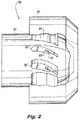
- FIG. 1 an illustrative view of an embodiment of a fuel nozzle in accordance with the disclosure is shown in Fig. 1 and is designated generally by reference character 100.
- FIGs. 2-14 Other embodiments and/or aspects of this disclosure are shown in Figs. 2-14 .
- the systems and methods described herein can be used to reduce and/or eliminate backflow, improve air wiping of potential carbon buildup surfaces, improve gas mixing, and/or for any other suitable purpose.
- a fuel injector 100 (e.g., which can be a tip of a fuel injector system) can include an annular body 101 defining a gas fuel inlet 103 therein.
- the gas fuel inlet 103 can include any suitable shape (e.g., an annular cavity defined in the annular body 101 and/or individual axial channels defined in the annular body 101).
- the fuel injector 100 can include a structure 105 extending radially outward from the annular body 101 and configured to extend into an air circuit 107.
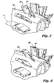
- the structure 105 can include a gas channel 109 defined within the structure 105 at least partially along a radial length 110 (e.g., the radial length as shown in Fig. 3 ) of the structure 105.
- the gas channel 109 is in fluid communication with the gas fuel inlet 103 where the structure 105 meets the annular body 101.
- the structure 105 also includes a slot opening 111 defined at least partially along a radial length 110 of the structure 105 and configured to fluidically connect the gas channel 109 and the air circuit 107 to all gas fuel to effuse into the air circuit 107.
- the fuel injector 100 can include a plurality of the structure 105. However, it is contemplated that the fuel injector 100 can include a single structure 105 for introducing gaseous fuel into the air circuit 107 and other structures can be solid vanes or support structures.
- the fuel injector 100 can include an air shroud 113 attached to (e.g., via brazing) or formed from (e.g., via additive manufacturing) a radially outward end 115 of the structure 105 to define the air circuit 107. It is contemplated herein the air shroud 113 can be disposed on or attached to the annular body 101 in any other suitable manner.
- At least some of the structures 105 can include an airfoil shape such that the structure 105 is also a vane of an air swirler (e.g., shown comprised of structures 105) that is configured to swirl air in the air circuit 107.
- an air swirler e.g., shown comprised of structures 105
- Any suitable vane geometry is contemplated herein. For example, certain embodiments do not have air swirling and only have straight struts for structures 105, for example.
- one or more, e.g., all, of the structures 105 need not extend across the entire air circuit 107 and can be any suitable radial length.
- the structures 105 may only extend partially into the air circuit 105 and the air shroud 113 can be supported on the annular body 101 in any other suitable manner by any other suitable support (e.g., a solid vane).
- the gas channel 109 and the slot opening 111 can be defined along the entire length of the structure 105.
- the gas channel 109 (not shown in Fig. 4 ) and/or the slot opening 411 of structure 405 can be defined only partially along the radially length of the structure 105. It is contemplated that the gas channel 109 can be longer than the slot 111 opening, or vice versa.
- the fuel injector 100 can include a liquid fuel circuit 112 and/or an inner air flow channel 114 defined by the annular body 101.
- the inner air flow channel 114 can include an inner air swirler 116, for example.
- the slot opening 111 is defined through a concave high pressure side 515 of the airfoil shape.
- the gas channel 105 can be sized and/or shaped relative to the slot opening 111, 411 to cause uniform flow distribution through the slot opening, e.g., to cause flow ribboning of the gaseous fuel into the air stream.
- the slot opening 111, 411 can constrict flow from the gas channel 105 (e.g., to affect pressure to cause gas to fill the gas channel uniformly). This can be accomplished by a stepped or smooth reduction in flow area to a constant flow area, e.g., as shown in Figs 1 - 5 .
- Figs. 6 to 10 show portions of various embodiments of fuel injectors in accordance with this disclosure, shown having only a gaseous fuel circuit for simplicity. Any suitable number of fuel circuits and/or additional types (e.g., liquid fuel) is contemplated herein.
- the fuel injector 1100, 1200 can include an additional gas outlet 1119, 1219 to all gas fuel to effuse from the gas fuel inlet 1103, 1203.
- the additional gas outlet 1119 can be defined axially through the annular body 1101.
- the additional gas outlet 1219 can be defined radially outward of the air circuit 1207 in the air shroud 1213 such that the additional gas outlet 1219 is in fluid communication with the air circuit 1207.
- the additional gas outlet 1219 can be in fluid communication with the gas fuel inlet 1203 of the annular body 1201 through a strut 1221 that includes a slot or passage therein, the strut 1221 passing through the air circuit 1207.
- the strut 1221 can include an airfoil shape for example and can form part of an air swirler.
- the strut 1221 can be axially separated from the structure 105, or can be circumferentially disposed.
- airfoils of an air swirler can alternate being a structure 105 as disclosed herein or a strut 1221.
- the fuel injector 1300, 1400 can include a second air shroud 1323, 1423 disposed radially outward of the air shroud 1313, 1413 that is formed from or attached to the structure 105.
- the second air shroud 1323, 1423 can define a second air circuit 1325, 1425.
- an additional gas outlet 1419 can be included to allow gas fuel to effuse from the gas fuel inlet 1403. As shown in Fig. 10 , the additional gas outlet 1419 can be defined between the air shroud 1413 that is formed from or attached to the structure 105 and the second air shroud 1425.
- the additional gas outlet 1419 can be connected to the gas fuel inlet 1403 through a strut 1421, e.g., similar to strut 1221 as described above, for example.
- the additional gas outlet 1419 can be in fluid communication with the second air circuit 1425 as shown.
- a method for making a fuel injector can include forming a structure as described above.
- Forming the structure can include additively manufacturing the structure, or forming the structure to include an entirely internal gas channel and cutting a trailing edge off of the structure to form the slot opening, for example. Any other suitable method of forming is contemplated herein.
- an air circuit strut for a fuel injector can include a gas channel defined therein and open through a slot opening in fluid communication with air in the air circuit.
- Embodiments can include any suitable number of upstream or downstream gas circuits (e.g., two separate upstream circuits for flexibility).
- Embodiments allow gaseous fuel to travel through the vanes into an air circuit (e.g., having a swirler) swirler. Slot openings allow good mixing with air. Embodiments also change the geometry as compared to traditional injectors such that embodiments disclosed herein reduce or eliminates pull back of liquid fuel particles and/or cause adequate wiping of surfaces where deposits would form since there is not a separate large gas swirling circuit which prevents adequate wiping.
- an air circuit e.g., having a swirler
- Slot openings allow good mixing with air.
- Embodiments also change the geometry as compared to traditional injectors such that embodiments disclosed herein reduce or eliminates pull back of liquid fuel particles and/or cause adequate wiping of surfaces where deposits would form since there is not a separate large gas swirling circuit which prevents adequate wiping.
- Embodiments for a non-premixed injector can include gaseous fuel passages that extend into the air circuit, e.g., at swirl vanes and exits the vane as a near collinear gap along the majority of air vane height.
- Embodiments alternatively or additionally can locate gaseous fuel exit(s) near the inner diameter or outer diameter of air circuit swirl vanes, e.g., where recirculation liquid fuel droplet is not possible.
- Embodiments eliminate or reduce propensity of liquid fuel backflow into gas or air circuits, improve the purge of gas circuit from previous designs, and provide options for better gas mixing into the air stream.
- Embodiments also allow for creation of designed local rich or lean zones and/or about a 50% more gaseous fuel surface area.
- Embodiments can allow for the gas fuel to mix into the air stream without consequence of liquid fuel droplet recirculation and resulting carbon growth.
- Embodiments include greater surface area interaction and placement for rich/lean zones as desired for combustion performance.
- any numerical values disclosed herein can be exact values or can be values within a range. Further, any terms of approximation (e.g., “about”, “approximately”, “around”) used in this disclosure can mean the stated value within a range. For example, in certain embodiments, the range can be within (plus or minus) 20%, or within 10%, or within 5%, or within 2%, or within any other suitable percentage or number as appreciated by those having ordinary skill in the art (e.g., for known tolerance limits or error ranges).
Landscapes
- Engineering & Computer Science (AREA)
- Chemical & Material Sciences (AREA)
- Combustion & Propulsion (AREA)
- Mechanical Engineering (AREA)
- General Engineering & Computer Science (AREA)
- Turbine Rotor Nozzle Sealing (AREA)
- Fuel-Injection Apparatus (AREA)
- Fuel Cell (AREA)
Claims (13)
- Kraftstoffinjektor, umfassend:einen ringförmigen Körper (101), der einen Brenngaseinlass (103) darin definiert; undeine Struktur (105), die sich radial auswärts von dem ringförmigen Körper aus erstreckt und so konfiguriert ist, dass sie sich in einen Luftkreislauf (107) erstreckt, wobei die Struktur Folgendes definiert:einen Gaskanal (109), der innerhalb der Struktur mindestens teilweise entlang einer radialen Länge der Struktur definiert ist, wobei der Gaskanal in Fluidverbindung mit dem Brenngaseinlass steht, wo die Struktur auf den ringförmigen Körper trifft; undeine Schlitzöffnung (111), die mindestens teilweise entlang der radialen Länge der Struktur definiert ist und so konfiguriert ist, dass sie den Gaskanal fluidmäßig mit dem Luftkreislauf verbindet, um es dem Brenngas zu ermöglichen, in den Luftkreislauf auszuströmen;wobei die Struktur (105) eine Schaufelprofilform beinhaltet, so dass die Struktur (105) eine Leitschaufel eines Luftverwirblers (116) ist, der so konfiguriert ist, dass er Luft in den Luftkreislauf wirbelt,dadurch gekennzeichnet, dassdie Schlitzöffnung durch eine konkave Hochdruckseite der Schaufelprofilform definiert ist.
- Kraftstoffinjektor nach Anspruch 1, ferner eine Vielzahl der Struktur umfassend.
- Kraftstoffinjektor nach Anspruch 2, ferner eine Luftführung (113) umfassend, die an einem radial auswärtigen Ende der Struktur angebracht oder von dieser aus ausgebildet ist, um den Luftkreislauf zu definieren.
- Kraftstoffinjektor nach einem der vorstehenden Ansprüche, wobei der Gaskanal und die Schlitzöffnung entlang der gesamten Länge der Struktur definiert sind.
- Kraftstoffinjektor nach einem der vorstehenden Ansprüche, wobei der Gaskanal relativ zur Schlitzöffnung so bemessen und/oder geformt ist, dass er eine gleichmäßige Strömungsverteilung durch die Schlitzöffnung bewirkt, um eine Strömungsbänderung zu bewirken, und vorzugsweise wobei die Schlitzöffnung den Strom von dem Gaskanal verengt.
- Kraftstoffinjektor nach Anspruch 5, wobei der Gaskanal und die Schlitzöffnung durch einen einzigen, sich stufenlos verkleinernden Kanal definiert sind.
- Kraftstoffinjektor nach einem der vorstehenden Ansprüche, ferner einen zusätzlichen Gasauslass (1119) umfassend, um es dem Brenngas zu ermöglichen, von dem Brenngaseinlass auszuströmen.
- Kraftstoffinjektor nach Anspruch 7, wobei der zusätzliche Gasauslass axial durch den ringförmigen Körper definiert ist, oder
wobei der zusätzliche Gasauslass radial auswärts des Luftkreislaufs in einer Luftführung in Fluidverbindung mit dem Luftkreislauf definiert ist, wobei der zusätzliche Gasauslass in Fluidverbindung mit dem Brenngaseinlass des ringförmigen Körpers durch eine Strebe steht, die durch den Luftkreislauf verläuft. - Kraftstoffinjektor nach Anspruch 3 oder jedem davon abhängigen Anspruch, ferner eine zweite Luftführung (1323) umfassend, die radial auswärts der Luftführung angeordnet ist, die von der Struktur aus ausgebildet oder an dieser angebracht ist, wobei die zweite Luftführung einen zweiten Luftkreislauf definiert.
- Kraftstoffinjektor nach Anspruch 9, ferner einen zusätzlichen Gas(1219)auslass umfassend, um das gesamte Brenngas von dem Brenngaseinlass ausströmen zu lassen, wobei der zusätzliche Gasauslass zwischen der Luftverkleidung, die von der Struktur aus ausgebildet oder an dieser angebracht ist, oder der zweiten Luftverkleidung definiert ist, wobei der zusätzliche Gasauslass in Fluidverbindung mit dem zweiten Luftkreislauf steht.
- Kraftstoffinjektor nach einem der vorstehenden Ansprüche, ferner einen Flüssigkraftstoffkreislauf (112) und/oder einen inneren Luftströmungskanal (114) umfassend, der durch den ringförmigen Körper definiert ist.
- Kraftstoffinjektor nach Anspruch 11, wobei der innere Luftströmungskanal einen inneren Luftverwirbler (116) beinhaltet.
- Verfahren zum Herstellen eines Kraftstoffinjektors nach einem der vorstehenden Ansprüche, umfassend:Ausbilden einer Struktur, die sich radial auswärts von einem ringförmigen Körper erstreckt und so konfiguriert ist, dass sie sich in einen Luftkreislauf erstreckt, wobei die Struktur Folgendes definiert:einen Gaskanal, der innerhalb der Struktur mindestens teilweise entlang einer radialen Länge der Struktur definiert ist, wobei der Gaskanal in Fluidverbindung mit einem Brenngaseinlass steht, wo die Struktur auf den ringförmigen Körper trifft; undeine Schlitzöffnung, die mindestens teilweise entlang der radialen Länge der Struktur definiert ist und so konfiguriert ist, dass sie eine Fluidverbindung zwischen dem Gaskanal und dem Luftkreislauf herstellt, um es dem Brenngas zu ermöglichen, in den Luftkreislauf auszuströmen;wobei die Schlitzöffnung durch eine konkave Hochdruckseite der Schaufelprofilform definiert ist.
Applications Claiming Priority (1)
| Application Number | Priority Date | Filing Date | Title |
|---|---|---|---|
| US15/902,800 US10941938B2 (en) | 2018-02-22 | 2018-02-22 | Fuel injectors including gas fuel injection |
Publications (2)
| Publication Number | Publication Date |
|---|---|
| EP3531022A1 EP3531022A1 (de) | 2019-08-28 |
| EP3531022B1 true EP3531022B1 (de) | 2021-09-22 |
Family
ID=65520179
Family Applications (1)
| Application Number | Title | Priority Date | Filing Date |
|---|---|---|---|
| EP19158626.2A Active EP3531022B1 (de) | 2018-02-22 | 2019-02-21 | Kraftstoffinjektoren mit gaskraftstoffinjektion |
Country Status (2)
| Country | Link |
|---|---|
| US (1) | US10941938B2 (de) |
| EP (1) | EP3531022B1 (de) |
Families Citing this family (9)
| Publication number | Priority date | Publication date | Assignee | Title |
|---|---|---|---|---|
| US11906165B2 (en) * | 2021-12-21 | 2024-02-20 | General Electric Company | Gas turbine nozzle having an inner air swirler passage and plural exterior fuel passages |
| EP4202302B1 (de) | 2021-12-21 | 2025-12-24 | General Electric Company | Brennstoffdüse und verwirbler |
| JP7729413B2 (ja) * | 2022-02-08 | 2025-08-26 | 株式会社Ihi | 噴射ノズルおよび燃焼装置 |
| US12111056B2 (en) * | 2023-02-02 | 2024-10-08 | Pratt & Whitney Canada Corp. | Combustor with central fuel injection and downstream air mixing |
| US12276424B1 (en) * | 2023-10-07 | 2025-04-15 | Honeywell International Inc. | Fuel nozzle having inner and outer mixing chambers fed with fuel via first and second hole patterns |
| US12281796B1 (en) * | 2024-03-18 | 2025-04-22 | Pratt & Whitney Canada Corp. | Combustion system with dual fuel capability |
| US12326256B1 (en) * | 2024-04-04 | 2025-06-10 | Rtx Corporation | Fuel nozzle for hydrogen-based fuel operation |
| US12181152B1 (en) * | 2024-04-04 | 2024-12-31 | Rtx Corporation | Fuel nozzle for hydrogen-based fuel operation |
| US12234988B1 (en) * | 2024-04-04 | 2025-02-25 | Rtx Corporation | Fuel nozzle for hydrogen-based fuel operation |
Family Cites Families (23)
| Publication number | Priority date | Publication date | Assignee | Title |
|---|---|---|---|---|
| GB1139004A (en) * | 1966-02-28 | 1969-01-08 | Mini Of Technology | Improvements in or relating to combustion devices |
| US5351477A (en) * | 1993-12-21 | 1994-10-04 | General Electric Company | Dual fuel mixer for gas turbine combustor |
| JPH09137946A (ja) | 1995-11-15 | 1997-05-27 | Mitsubishi Heavy Ind Ltd | 燃焼器の燃料ノズル |
| JP4205231B2 (ja) * | 1998-02-10 | 2009-01-07 | ゼネラル・エレクトリック・カンパニイ | バーナ |
| US6898937B2 (en) * | 2002-07-15 | 2005-05-31 | Power Systems Mfg., Llc | Gas only fin mixer secondary fuel nozzle |
| US6691516B2 (en) * | 2002-07-15 | 2004-02-17 | Power Systems Mfg, Llc | Fully premixed secondary fuel nozzle with improved stability |
| US7165405B2 (en) * | 2002-07-15 | 2007-01-23 | Power Systems Mfg. Llc | Fully premixed secondary fuel nozzle with dual fuel capability |
| US6722132B2 (en) * | 2002-07-15 | 2004-04-20 | Power Systems Mfg, Llc | Fully premixed secondary fuel nozzle with improved stability and dual fuel capability |
| US6675581B1 (en) * | 2002-07-15 | 2004-01-13 | Power Systems Mfg, Llc | Fully premixed secondary fuel nozzle |
| US6983601B2 (en) * | 2004-05-28 | 2006-01-10 | General Electric Company | Method and apparatus for gas turbine engines |
| US6993916B2 (en) * | 2004-06-08 | 2006-02-07 | General Electric Company | Burner tube and method for mixing air and gas in a gas turbine engine |
| US7546735B2 (en) * | 2004-10-14 | 2009-06-16 | General Electric Company | Low-cost dual-fuel combustor and related method |
| JP2006300448A (ja) | 2005-04-22 | 2006-11-02 | Mitsubishi Heavy Ind Ltd | ガスタービンの燃焼器 |
| US7490471B2 (en) * | 2005-12-08 | 2009-02-17 | General Electric Company | Swirler assembly |
| US20080078182A1 (en) * | 2006-09-29 | 2008-04-03 | Andrei Tristan Evulet | Premixing device, gas turbines comprising the premixing device, and methods of use |
| US20080078183A1 (en) | 2006-10-03 | 2008-04-03 | General Electric Company | Liquid fuel enhancement for natural gas swirl stabilized nozzle and method |
| US8661779B2 (en) * | 2008-09-26 | 2014-03-04 | Siemens Energy, Inc. | Flex-fuel injector for gas turbines |
| US8104286B2 (en) | 2009-01-07 | 2012-01-31 | General Electric Company | Methods and systems to enhance flame holding in a gas turbine engine |
| US20100180599A1 (en) * | 2009-01-21 | 2010-07-22 | Thomas Stephen R | Insertable Pre-Drilled Swirl Vane for Premixing Fuel Nozzle |
| US20100287938A1 (en) * | 2009-05-14 | 2010-11-18 | General Electric Company | Cross flow vane |
| EP2362148A1 (de) * | 2010-02-23 | 2011-08-31 | Siemens Aktiengesellschaft | Brennstoffinjektor und Drallvorrichtung mit lappenartigem Mischer |
| US9557050B2 (en) * | 2010-07-30 | 2017-01-31 | General Electric Company | Fuel nozzle and assembly and gas turbine comprising the same |
| US20140291418A1 (en) | 2013-03-26 | 2014-10-02 | Parker-Hannifin Corporation | Multi-circuit airblast fuel nozzle |
-
2018
- 2018-02-22 US US15/902,800 patent/US10941938B2/en active Active
-
2019
- 2019-02-21 EP EP19158626.2A patent/EP3531022B1/de active Active
Also Published As
| Publication number | Publication date |
|---|---|
| US10941938B2 (en) | 2021-03-09 |
| US20190257520A1 (en) | 2019-08-22 |
| EP3531022A1 (de) | 2019-08-28 |
Similar Documents
| Publication | Publication Date | Title |
|---|---|---|
| US10941938B2 (en) | Fuel injectors including gas fuel injection | |
| US12055295B2 (en) | Fuel nozzle structure for air assist injection | |
| US8387391B2 (en) | Aerodynamically enhanced fuel nozzle | |
| US11655979B2 (en) | Airblast fuel nozzle | |
| US8726668B2 (en) | Fuel atomization dual orifice fuel nozzle | |
| JP5008401B2 (ja) | 特にジェットエンジンの燃焼チャンバ用多モード燃料噴射器の冷却 | |
| EP2466206A2 (de) | Kühlmitteldurchlauf-Schmutzableiter in einer Kraftstoffdüse | |
| US12130013B2 (en) | Swirler-ferrule assembly | |
| US20030164410A1 (en) | Nozzle with flow equalizer | |
| US8555649B2 (en) | Fuel nozzle swirler assembly | |
| US11739936B2 (en) | Injection system for turbomachine, comprising a swirler and mixing bowl vortex holes | |
| US20120227408A1 (en) | Systems and methods of pressure drop control in fluid circuits through swirling flow mitigation | |
| AU2007203536A1 (en) | Liquid fuel enhancement for natural gas swirl stabilized nozzle and method | |
| EP3611433B1 (de) | Luftbrause mit verbessertem luftwischen | |
| EP3054219B1 (de) | Luftummantelungen mit luftspülung | |
| JP4096056B2 (ja) | ガスタービン用燃料ノズル | |
| CN109073224B (zh) | 用于涡轮机喷射系统的、在入口处包括气动偏转器的进气旋流器 | |
| EP2570727B1 (de) | Injektor mit Druckabfallregelung in Flüssigkeitskreisläufen durch Wirbelstromabschwächung | |
| KR20250169280A (ko) | 개선된 버너 부품, 및 이러한 버너 부품을 갖는 버너 | |
| EP0165050A2 (de) | Kraftstoffdüse |
Legal Events
| Date | Code | Title | Description |
|---|---|---|---|
| PUAI | Public reference made under article 153(3) epc to a published international application that has entered the european phase |
Free format text: ORIGINAL CODE: 0009012 |
|
| STAA | Information on the status of an ep patent application or granted ep patent |
Free format text: STATUS: THE APPLICATION HAS BEEN PUBLISHED |
|
| AK | Designated contracting states |
Kind code of ref document: A1 Designated state(s): AL AT BE BG CH CY CZ DE DK EE ES FI FR GB GR HR HU IE IS IT LI LT LU LV MC MK MT NL NO PL PT RO RS SE SI SK SM TR |
|
| AX | Request for extension of the european patent |
Extension state: BA ME |
|
| STAA | Information on the status of an ep patent application or granted ep patent |
Free format text: STATUS: REQUEST FOR EXAMINATION WAS MADE |
|
| 17P | Request for examination filed |
Effective date: 20191216 |
|
| RBV | Designated contracting states (corrected) |
Designated state(s): AL AT BE BG CH CY CZ DE DK EE ES FI FR GB GR HR HU IE IS IT LI LT LU LV MC MK MT NL NO PL PT RO RS SE SI SK SM TR |
|
| RIN1 | Information on inventor provided before grant (corrected) |
Inventor name: PROCIW, LEV ALEXANDER Inventor name: ZINK, GREGORY Inventor name: OCKEN, THOMAS J. Inventor name: TIBBS, ANDY W. |
|
| STAA | Information on the status of an ep patent application or granted ep patent |
Free format text: STATUS: EXAMINATION IS IN PROGRESS |
|
| 17Q | First examination report despatched |
Effective date: 20200528 |
|
| GRAP | Despatch of communication of intention to grant a patent |
Free format text: ORIGINAL CODE: EPIDOSNIGR1 |
|
| STAA | Information on the status of an ep patent application or granted ep patent |
Free format text: STATUS: GRANT OF PATENT IS INTENDED |
|
| INTG | Intention to grant announced |
Effective date: 20210419 |
|
| GRAS | Grant fee paid |
Free format text: ORIGINAL CODE: EPIDOSNIGR3 |
|
| GRAA | (expected) grant |
Free format text: ORIGINAL CODE: 0009210 |
|
| STAA | Information on the status of an ep patent application or granted ep patent |
Free format text: STATUS: THE PATENT HAS BEEN GRANTED |
|
| AK | Designated contracting states |
Kind code of ref document: B1 Designated state(s): AL AT BE BG CH CY CZ DE DK EE ES FI FR GB GR HR HU IE IS IT LI LT LU LV MC MK MT NL NO PL PT RO RS SE SI SK SM TR |
|
| REG | Reference to a national code |
Ref country code: GB Ref legal event code: FG4D |
|
| REG | Reference to a national code |
Ref country code: DE Ref legal event code: R096 Ref document number: 602019007766 Country of ref document: DE |
|
| REG | Reference to a national code |
Ref country code: IE Ref legal event code: FG4D |
|
| REG | Reference to a national code |
Ref country code: CH Ref legal event code: EP Ref country code: AT Ref legal event code: REF Ref document number: 1432618 Country of ref document: AT Kind code of ref document: T Effective date: 20211015 |
|
| REG | Reference to a national code |
Ref country code: LT Ref legal event code: MG9D |
|
| REG | Reference to a national code |
Ref country code: NL Ref legal event code: MP Effective date: 20210922 |
|
| PG25 | Lapsed in a contracting state [announced via postgrant information from national office to epo] |
Ref country code: RS Free format text: LAPSE BECAUSE OF FAILURE TO SUBMIT A TRANSLATION OF THE DESCRIPTION OR TO PAY THE FEE WITHIN THE PRESCRIBED TIME-LIMIT Effective date: 20210922 Ref country code: SE Free format text: LAPSE BECAUSE OF FAILURE TO SUBMIT A TRANSLATION OF THE DESCRIPTION OR TO PAY THE FEE WITHIN THE PRESCRIBED TIME-LIMIT Effective date: 20210922 Ref country code: FI Free format text: LAPSE BECAUSE OF FAILURE TO SUBMIT A TRANSLATION OF THE DESCRIPTION OR TO PAY THE FEE WITHIN THE PRESCRIBED TIME-LIMIT Effective date: 20210922 Ref country code: NO Free format text: LAPSE BECAUSE OF FAILURE TO SUBMIT A TRANSLATION OF THE DESCRIPTION OR TO PAY THE FEE WITHIN THE PRESCRIBED TIME-LIMIT Effective date: 20211222 Ref country code: HR Free format text: LAPSE BECAUSE OF FAILURE TO SUBMIT A TRANSLATION OF THE DESCRIPTION OR TO PAY THE FEE WITHIN THE PRESCRIBED TIME-LIMIT Effective date: 20210922 Ref country code: LT Free format text: LAPSE BECAUSE OF FAILURE TO SUBMIT A TRANSLATION OF THE DESCRIPTION OR TO PAY THE FEE WITHIN THE PRESCRIBED TIME-LIMIT Effective date: 20210922 Ref country code: BG Free format text: LAPSE BECAUSE OF FAILURE TO SUBMIT A TRANSLATION OF THE DESCRIPTION OR TO PAY THE FEE WITHIN THE PRESCRIBED TIME-LIMIT Effective date: 20211222 |
|
| REG | Reference to a national code |
Ref country code: AT Ref legal event code: MK05 Ref document number: 1432618 Country of ref document: AT Kind code of ref document: T Effective date: 20210922 |
|
| PG25 | Lapsed in a contracting state [announced via postgrant information from national office to epo] |
Ref country code: LV Free format text: LAPSE BECAUSE OF FAILURE TO SUBMIT A TRANSLATION OF THE DESCRIPTION OR TO PAY THE FEE WITHIN THE PRESCRIBED TIME-LIMIT Effective date: 20210922 Ref country code: GR Free format text: LAPSE BECAUSE OF FAILURE TO SUBMIT A TRANSLATION OF THE DESCRIPTION OR TO PAY THE FEE WITHIN THE PRESCRIBED TIME-LIMIT Effective date: 20211223 |
|
| PG25 | Lapsed in a contracting state [announced via postgrant information from national office to epo] |
Ref country code: AT Free format text: LAPSE BECAUSE OF FAILURE TO SUBMIT A TRANSLATION OF THE DESCRIPTION OR TO PAY THE FEE WITHIN THE PRESCRIBED TIME-LIMIT Effective date: 20210922 |
|
| RAP4 | Party data changed (patent owner data changed or rights of a patent transferred) |
Owner name: COLLINS ENGINE NOZZLES, INC. |
|
| PG25 | Lapsed in a contracting state [announced via postgrant information from national office to epo] |
Ref country code: IS Free format text: LAPSE BECAUSE OF FAILURE TO SUBMIT A TRANSLATION OF THE DESCRIPTION OR TO PAY THE FEE WITHIN THE PRESCRIBED TIME-LIMIT Effective date: 20220122 Ref country code: SK Free format text: LAPSE BECAUSE OF FAILURE TO SUBMIT A TRANSLATION OF THE DESCRIPTION OR TO PAY THE FEE WITHIN THE PRESCRIBED TIME-LIMIT Effective date: 20210922 Ref country code: RO Free format text: LAPSE BECAUSE OF FAILURE TO SUBMIT A TRANSLATION OF THE DESCRIPTION OR TO PAY THE FEE WITHIN THE PRESCRIBED TIME-LIMIT Effective date: 20210922 Ref country code: PT Free format text: LAPSE BECAUSE OF FAILURE TO SUBMIT A TRANSLATION OF THE DESCRIPTION OR TO PAY THE FEE WITHIN THE PRESCRIBED TIME-LIMIT Effective date: 20220124 Ref country code: PL Free format text: LAPSE BECAUSE OF FAILURE TO SUBMIT A TRANSLATION OF THE DESCRIPTION OR TO PAY THE FEE WITHIN THE PRESCRIBED TIME-LIMIT Effective date: 20210922 Ref country code: NL Free format text: LAPSE BECAUSE OF FAILURE TO SUBMIT A TRANSLATION OF THE DESCRIPTION OR TO PAY THE FEE WITHIN THE PRESCRIBED TIME-LIMIT Effective date: 20210922 Ref country code: ES Free format text: LAPSE BECAUSE OF FAILURE TO SUBMIT A TRANSLATION OF THE DESCRIPTION OR TO PAY THE FEE WITHIN THE PRESCRIBED TIME-LIMIT Effective date: 20210922 Ref country code: EE Free format text: LAPSE BECAUSE OF FAILURE TO SUBMIT A TRANSLATION OF THE DESCRIPTION OR TO PAY THE FEE WITHIN THE PRESCRIBED TIME-LIMIT Effective date: 20210922 Ref country code: CZ Free format text: LAPSE BECAUSE OF FAILURE TO SUBMIT A TRANSLATION OF THE DESCRIPTION OR TO PAY THE FEE WITHIN THE PRESCRIBED TIME-LIMIT Effective date: 20210922 Ref country code: AL Free format text: LAPSE BECAUSE OF FAILURE TO SUBMIT A TRANSLATION OF THE DESCRIPTION OR TO PAY THE FEE WITHIN THE PRESCRIBED TIME-LIMIT Effective date: 20210922 |
|
| REG | Reference to a national code |
Ref country code: DE Ref legal event code: R097 Ref document number: 602019007766 Country of ref document: DE |
|
| PG25 | Lapsed in a contracting state [announced via postgrant information from national office to epo] |
Ref country code: DK Free format text: LAPSE BECAUSE OF FAILURE TO SUBMIT A TRANSLATION OF THE DESCRIPTION OR TO PAY THE FEE WITHIN THE PRESCRIBED TIME-LIMIT Effective date: 20210922 |
|
| PLBE | No opposition filed within time limit |
Free format text: ORIGINAL CODE: 0009261 |
|
| STAA | Information on the status of an ep patent application or granted ep patent |
Free format text: STATUS: NO OPPOSITION FILED WITHIN TIME LIMIT |
|
| 26N | No opposition filed |
Effective date: 20220623 |
|
| PG25 | Lapsed in a contracting state [announced via postgrant information from national office to epo] |
Ref country code: MC Free format text: LAPSE BECAUSE OF FAILURE TO SUBMIT A TRANSLATION OF THE DESCRIPTION OR TO PAY THE FEE WITHIN THE PRESCRIBED TIME-LIMIT Effective date: 20210922 |
|
| REG | Reference to a national code |
Ref country code: CH Ref legal event code: PL |
|
| REG | Reference to a national code |
Ref country code: BE Ref legal event code: MM Effective date: 20220228 |
|
| PG25 | Lapsed in a contracting state [announced via postgrant information from national office to epo] |
Ref country code: LU Free format text: LAPSE BECAUSE OF NON-PAYMENT OF DUE FEES Effective date: 20220221 |
|
| PG25 | Lapsed in a contracting state [announced via postgrant information from national office to epo] |
Ref country code: SI Free format text: LAPSE BECAUSE OF FAILURE TO SUBMIT A TRANSLATION OF THE DESCRIPTION OR TO PAY THE FEE WITHIN THE PRESCRIBED TIME-LIMIT Effective date: 20210922 |
|
| PG25 | Lapsed in a contracting state [announced via postgrant information from national office to epo] |
Ref country code: LI Free format text: LAPSE BECAUSE OF NON-PAYMENT OF DUE FEES Effective date: 20220228 Ref country code: IT Free format text: LAPSE BECAUSE OF FAILURE TO SUBMIT A TRANSLATION OF THE DESCRIPTION OR TO PAY THE FEE WITHIN THE PRESCRIBED TIME-LIMIT Effective date: 20210922 Ref country code: IE Free format text: LAPSE BECAUSE OF NON-PAYMENT OF DUE FEES Effective date: 20220221 Ref country code: CH Free format text: LAPSE BECAUSE OF NON-PAYMENT OF DUE FEES Effective date: 20220228 |
|
| PG25 | Lapsed in a contracting state [announced via postgrant information from national office to epo] |
Ref country code: BE Free format text: LAPSE BECAUSE OF NON-PAYMENT OF DUE FEES Effective date: 20220228 |
|
| P01 | Opt-out of the competence of the unified patent court (upc) registered |
Effective date: 20230530 |
|
| PG25 | Lapsed in a contracting state [announced via postgrant information from national office to epo] |
Ref country code: SM Free format text: LAPSE BECAUSE OF FAILURE TO SUBMIT A TRANSLATION OF THE DESCRIPTION OR TO PAY THE FEE WITHIN THE PRESCRIBED TIME-LIMIT Effective date: 20210922 Ref country code: MK Free format text: LAPSE BECAUSE OF FAILURE TO SUBMIT A TRANSLATION OF THE DESCRIPTION OR TO PAY THE FEE WITHIN THE PRESCRIBED TIME-LIMIT Effective date: 20210922 Ref country code: CY Free format text: LAPSE BECAUSE OF FAILURE TO SUBMIT A TRANSLATION OF THE DESCRIPTION OR TO PAY THE FEE WITHIN THE PRESCRIBED TIME-LIMIT Effective date: 20210922 |
|
| PG25 | Lapsed in a contracting state [announced via postgrant information from national office to epo] |
Ref country code: HU Free format text: LAPSE BECAUSE OF FAILURE TO SUBMIT A TRANSLATION OF THE DESCRIPTION OR TO PAY THE FEE WITHIN THE PRESCRIBED TIME-LIMIT; INVALID AB INITIO Effective date: 20190221 |
|
| PG25 | Lapsed in a contracting state [announced via postgrant information from national office to epo] |
Ref country code: MT Free format text: LAPSE BECAUSE OF FAILURE TO SUBMIT A TRANSLATION OF THE DESCRIPTION OR TO PAY THE FEE WITHIN THE PRESCRIBED TIME-LIMIT Effective date: 20210922 |
|
| PG25 | Lapsed in a contracting state [announced via postgrant information from national office to epo] |
Ref country code: TR Free format text: LAPSE BECAUSE OF FAILURE TO SUBMIT A TRANSLATION OF THE DESCRIPTION OR TO PAY THE FEE WITHIN THE PRESCRIBED TIME-LIMIT Effective date: 20210922 |
|
| PGFP | Annual fee paid to national office [announced via postgrant information from national office to epo] |
Ref country code: GB Payment date: 20260121 Year of fee payment: 8 |
|
| PGFP | Annual fee paid to national office [announced via postgrant information from national office to epo] |
Ref country code: DE Payment date: 20260121 Year of fee payment: 8 |
|
| PGFP | Annual fee paid to national office [announced via postgrant information from national office to epo] |
Ref country code: FR Payment date: 20260121 Year of fee payment: 8 |