EP3530889A1 - Steuerungsverfahren und -vorrichtung für hydraulisch gesteuertes drehgetriebesystem eines motorrotors - Google Patents
Steuerungsverfahren und -vorrichtung für hydraulisch gesteuertes drehgetriebesystem eines motorrotors Download PDFInfo
- Publication number
- EP3530889A1 EP3530889A1 EP18769020.1A EP18769020A EP3530889A1 EP 3530889 A1 EP3530889 A1 EP 3530889A1 EP 18769020 A EP18769020 A EP 18769020A EP 3530889 A1 EP3530889 A1 EP 3530889A1
- Authority
- EP
- European Patent Office
- Prior art keywords
- turning
- hydraulic
- hydraulic cylinders
- hydraulic cylinder
- control
- Prior art date
- Legal status (The legal status is an assumption and is not a legal conclusion. Google has not performed a legal analysis and makes no representation as to the accuracy of the status listed.)
- Granted
Links
Images



Classifications
-
- F—MECHANICAL ENGINEERING; LIGHTING; HEATING; WEAPONS; BLASTING
- F03—MACHINES OR ENGINES FOR LIQUIDS; WIND, SPRING, OR WEIGHT MOTORS; PRODUCING MECHANICAL POWER OR A REACTIVE PROPULSIVE THRUST, NOT OTHERWISE PROVIDED FOR
- F03D—WIND MOTORS
- F03D7/00—Controlling wind motors
- F03D7/02—Controlling wind motors the wind motors having rotation axis substantially parallel to the air flow entering the rotor
- F03D7/022—Adjusting aerodynamic properties of the blades
- F03D7/0224—Adjusting blade pitch
-
- F—MECHANICAL ENGINEERING; LIGHTING; HEATING; WEAPONS; BLASTING
- F03—MACHINES OR ENGINES FOR LIQUIDS; WIND, SPRING, OR WEIGHT MOTORS; PRODUCING MECHANICAL POWER OR A REACTIVE PROPULSIVE THRUST, NOT OTHERWISE PROVIDED FOR
- F03D—WIND MOTORS
- F03D1/00—Wind motors with rotation axis substantially parallel to the air flow entering the rotor
- F03D1/06—Rotors
- F03D1/065—Rotors characterised by their construction elements
- F03D1/0691—Rotors characterised by their construction elements of the hub
-
- F—MECHANICAL ENGINEERING; LIGHTING; HEATING; WEAPONS; BLASTING
- F03—MACHINES OR ENGINES FOR LIQUIDS; WIND, SPRING, OR WEIGHT MOTORS; PRODUCING MECHANICAL POWER OR A REACTIVE PROPULSIVE THRUST, NOT OTHERWISE PROVIDED FOR
- F03D—WIND MOTORS
- F03D7/00—Controlling wind motors
-
- F—MECHANICAL ENGINEERING; LIGHTING; HEATING; WEAPONS; BLASTING
- F03—MACHINES OR ENGINES FOR LIQUIDS; WIND, SPRING, OR WEIGHT MOTORS; PRODUCING MECHANICAL POWER OR A REACTIVE PROPULSIVE THRUST, NOT OTHERWISE PROVIDED FOR
- F03D—WIND MOTORS
- F03D7/00—Controlling wind motors
- F03D7/02—Controlling wind motors the wind motors having rotation axis substantially parallel to the air flow entering the rotor
-
- F—MECHANICAL ENGINEERING; LIGHTING; HEATING; WEAPONS; BLASTING
- F03—MACHINES OR ENGINES FOR LIQUIDS; WIND, SPRING, OR WEIGHT MOTORS; PRODUCING MECHANICAL POWER OR A REACTIVE PROPULSIVE THRUST, NOT OTHERWISE PROVIDED FOR
- F03D—WIND MOTORS
- F03D7/00—Controlling wind motors
- F03D7/02—Controlling wind motors the wind motors having rotation axis substantially parallel to the air flow entering the rotor
- F03D7/026—Controlling wind motors the wind motors having rotation axis substantially parallel to the air flow entering the rotor for starting-up
-
- F—MECHANICAL ENGINEERING; LIGHTING; HEATING; WEAPONS; BLASTING
- F03—MACHINES OR ENGINES FOR LIQUIDS; WIND, SPRING, OR WEIGHT MOTORS; PRODUCING MECHANICAL POWER OR A REACTIVE PROPULSIVE THRUST, NOT OTHERWISE PROVIDED FOR
- F03D—WIND MOTORS
- F03D80/00—Details, components or accessories not provided for in groups F03D1/00 - F03D17/00
- F03D80/80—Arrangement of components within nacelles or towers
- F03D80/88—Arrangement of components within nacelles or towers of mechanical components
-
- F—MECHANICAL ENGINEERING; LIGHTING; HEATING; WEAPONS; BLASTING
- F05—INDEXING SCHEMES RELATING TO ENGINES OR PUMPS IN VARIOUS SUBCLASSES OF CLASSES F01-F04
- F05B—INDEXING SCHEME RELATING TO WIND, SPRING, WEIGHT, INERTIA OR LIKE MOTORS, TO MACHINES OR ENGINES FOR LIQUIDS COVERED BY SUBCLASSES F03B, F03D AND F03G
- F05B2220/00—Application
- F05B2220/30—Application in turbines
-
- F—MECHANICAL ENGINEERING; LIGHTING; HEATING; WEAPONS; BLASTING
- F05—INDEXING SCHEMES RELATING TO ENGINES OR PUMPS IN VARIOUS SUBCLASSES OF CLASSES F01-F04
- F05B—INDEXING SCHEME RELATING TO WIND, SPRING, WEIGHT, INERTIA OR LIKE MOTORS, TO MACHINES OR ENGINES FOR LIQUIDS COVERED BY SUBCLASSES F03B, F03D AND F03G
- F05B2240/00—Components
- F05B2240/20—Rotors
- F05B2240/21—Rotors for wind turbines
- F05B2240/221—Rotors for wind turbines with horizontal axis
-
- F—MECHANICAL ENGINEERING; LIGHTING; HEATING; WEAPONS; BLASTING
- F05—INDEXING SCHEMES RELATING TO ENGINES OR PUMPS IN VARIOUS SUBCLASSES OF CLASSES F01-F04
- F05B—INDEXING SCHEME RELATING TO WIND, SPRING, WEIGHT, INERTIA OR LIKE MOTORS, TO MACHINES OR ENGINES FOR LIQUIDS COVERED BY SUBCLASSES F03B, F03D AND F03G
- F05B2260/00—Function
- F05B2260/30—Retaining components in desired mutual position
- F05B2260/31—Locking rotor in position
-
- F—MECHANICAL ENGINEERING; LIGHTING; HEATING; WEAPONS; BLASTING
- F05—INDEXING SCHEMES RELATING TO ENGINES OR PUMPS IN VARIOUS SUBCLASSES OF CLASSES F01-F04
- F05B—INDEXING SCHEME RELATING TO WIND, SPRING, WEIGHT, INERTIA OR LIKE MOTORS, TO MACHINES OR ENGINES FOR LIQUIDS COVERED BY SUBCLASSES F03B, F03D AND F03G
- F05B2260/00—Function
- F05B2260/50—Kinematic linkage, i.e. transmission of position
- F05B2260/507—Kinematic linkage, i.e. transmission of position using servos, independent actuators, etc.
-
- F—MECHANICAL ENGINEERING; LIGHTING; HEATING; WEAPONS; BLASTING
- F05—INDEXING SCHEMES RELATING TO ENGINES OR PUMPS IN VARIOUS SUBCLASSES OF CLASSES F01-F04
- F05B—INDEXING SCHEME RELATING TO WIND, SPRING, WEIGHT, INERTIA OR LIKE MOTORS, TO MACHINES OR ENGINES FOR LIQUIDS COVERED BY SUBCLASSES F03B, F03D AND F03G
- F05B2270/00—Control
- F05B2270/60—Control system actuates through
- F05B2270/604—Control system actuates through hydraulic actuators
-
- Y—GENERAL TAGGING OF NEW TECHNOLOGICAL DEVELOPMENTS; GENERAL TAGGING OF CROSS-SECTIONAL TECHNOLOGIES SPANNING OVER SEVERAL SECTIONS OF THE IPC; TECHNICAL SUBJECTS COVERED BY FORMER USPC CROSS-REFERENCE ART COLLECTIONS [XRACs] AND DIGESTS
- Y02—TECHNOLOGIES OR APPLICATIONS FOR MITIGATION OR ADAPTATION AGAINST CLIMATE CHANGE
- Y02E—REDUCTION OF GREENHOUSE GAS [GHG] EMISSIONS, RELATED TO ENERGY GENERATION, TRANSMISSION OR DISTRIBUTION
- Y02E10/00—Energy generation through renewable energy sources
- Y02E10/70—Wind energy
- Y02E10/72—Wind turbines with rotation axis in wind direction
Definitions
- the present application relates to the technical field of wind power generators, and specifically to a control method and device for a hydraulic control turning system of a generator rotor.
- a generator of the wind power generator set is required to be equipped with a turning system in order to carry out the necessary turning operation in particular situations. For example, before re-starting a generator that has not been used for a long time, the bearing of the generator needs to be turned to facilitate forming an oil film; in the process of assembling the wind turbine, the turning operation is performed to cooperate with blade installation; and after the assembly is completed, a check turning operation is carried out to determine whether there is a situation in which a load (that is, a mechanical or transmission part) driven by the generator is stuck due to an increased resistance, so that the generator may not be damaged (i.e. burnout) by the increased starting load.
- a reliably operated turning system is a key indicator for the generator.
- a hydraulic control turning system driven by hydraulic cylinders is provided in the conventional technology, and the turning system is mounted on a nacelle base 10 and includes five driving units 20 as shown in Figure 1 .
- the turning system provides a driving force for turning by using five hydraulic cylinders 30.
- the hydraulic cylinders 30 each having one end fixed may drive matched driving units 20 to move, end cover holes of the generator 50 are uniformly distributed in a circumferential direction of an end cover 40 of the generator, and a turning pin 60 of each driving unit 20 moves to be aligned with the target end cover hole of the generator 50 and then is inserted into the hole, as shown in Figures 2 , 3 and 4 .
- extending or retracting the hydraulic cylinders 30 may just drive the end cover 40 of the generator to rotate, thereby realizing the turning operation.
- the hydraulic system in order to rotate the generator rotor (turning action), the hydraulic system is required to provide a rotation driving force for the generator rotor, and the turning operation driving hydraulic cylinders may drive the generator rotor to rotate by 7.5 degrees in one stroke.
- the hydraulic cylinders of the turning system return to their initial positions of the stroke one by one, so that a next rotor driving stroke can be performed.
- the turning system Limited by its own structure, the turning system generates a position error in each stroke, and after 16 strokes, the accumulated position error usually exceeds the position error allowed by design, which may cause that the turning pins of the turning system cannot be inserted into the end cover holes of the generator and thus the turning operation is failed.
- a control method and device for a hydraulic turning system of a generator rotor are provided according to the present application, which can dynamically correct the accumulated errors during the operation of the hydraulic control turning system, thereby greatly improving the operation accuracy and operation reliability of the turning system.
- the control method for a hydraulic control turning system of a generator rotor includes the following steps:
- the error correction positions are positions where the hydraulic cylinders are located after completing multiple driving strokes.
- the number of the driving strokes is determined depending on a working condition of the turning operation.
- the working condition of the turning operation is a working condition of blade installation.
- the following steps are performed:
- an insertion signal and a pullout signal of each of the turning pins are acquired to determine that the turning system meets the first starting condition.
- the method further includes: performing a limit position inspection for each of the multiple hydraulic cylinders, including: moving each of the multiple hydraulic cylinders to a limit position of the cylinder.
- the limit position inspection further includes acquiring lengths of the hydraulic cylinders at the limit positions to determine that the turning system meets a second starting condition.
- the reference hydraulic cylinder is a hydraulic cylinder of the multiple hydraulic cylinders having a minimum angle with respect a horizontal plane.
- a control device for a hydraulic control turning system of a generator rotor includes a first detecting unit, a storage unit and a control unit.
- the first detecting unit is configured to acquire current lengths of multiple hydraulic cylinders when the multiple hydraulic cylinders are located at error correction positions.
- the storage unit is configured to store a length relationship table between the multiple hydraulic cylinders of the hydraulic control turning system.
- the control unit is configured to adjust lengths of other hydraulic cylinders corresponding to a next driving stroke to conform to the length relationship table, with a current length of a reference hydraulic cylinder as a determining reference.
- the first detecting unit is further configured to acquire a reference length of the reference hydraulic cylinder when it is located at the target working position, to allow the control unit to control the multiple hydraulic cylinders to perform a function inspection of movement execution modules in sequence based on the reference length and the length relationship table.
- the function inspection of the movement execution modules includes: moving the multiple hydraulic cylinders to limit positions of the turning, and inserting the turning pin into the fitting hole or pull the turning pin out of the fitting hole.
- control unit is further configured to control the multiple hydraulic cylinders to each perform a limit position inspection, and the limit position inspection includes moving each of the multiple hydraulic cylinders to a limit position thereof.
- control device further includes: a second detecting unit configured to acquire an insertion signal and a pullout signal of each of the turning pins, and output the insertion signal and the pullout signal to the control unit to determine that the turning system meets a starting condition.
- a second detecting unit configured to acquire an insertion signal and a pullout signal of each of the turning pins, and output the insertion signal and the pullout signal to the control unit to determine that the turning system meets a starting condition.
- the above turning control technical solution is inventively provided according to the present application, and has the following beneficial effects compared with the conventional technology.
- an error correction may be performed at a selected position based on the length relationship table between the hydraulic cylinders of the hydraulic control turning system.
- a current length of the reference hydraulic cylinder is taken as a determining reference to adjust lengths of the other hydraulic cylinders corresponding to a next driving stroke to conform to the length relationship table.
- the error correction positions are positions where the hydraulic cylinders are located after completing multiple driving strokes, which can achieve a better dynamic error correction effect and also has good correction efficiency.
- the number of the driving strokes may be determined according to a working condition of the turning operation, and a dynamic correction and adjustment moment is selected according to the characteristics of different working conditions, thus the accuracy and error correction efficiency are balanced to the utmost extent.
- a turning start self-inspection step is provided according to another preferred solution of the present application.
- a reference length of the reference hydraulic cylinder when it is at the target working position is taken as a reference point, which is equivalent to the coordinate origin of the self-inspection step; and based on the inherent length relationships between the multiple hydraulic cylinders and the reference length of the reference hydraulic cylinder, the hydraulic cylinders are controlled to move in sequence to the turning limit positions, and are controlled to insert the turning pins into the fitting holes or to pull the turning pins out of the fitting holes, thereby determining that the first start condition is met, that is, the function inspection of the movement execution module is completed.
- the operation safety and reliability of the hydraulic control turning system can be effectively ensured, thereby greatly improving the operation efficiency of the whole device on the premise of completely avoiding the adverse effects of negative factors on the turning operation.
- a limit position inspection may be performed for the multiple hydraulic cylinders to verify that each hydraulic cylinder can move to its own limit position, and to confirm that the hydraulic cylinder itself has a good starting basis. Moreover, after the limit position inspection determines that the second starting condition is met, the function inspection of movement execution module is performed to ensure the reliability of the turning operation to the utmost extent.
- a hydraulic cylinder having a smallest angle with respect to the horizontal plane is preferably taken as the reference hydraulic cylinder, and the reference hydraulic cylinder has almost no load in a free state, or has a minimum load in a free state. Taking the reference hydraulic cylinder as a control reference may achieve the optimal accuracy.
- the hydraulic control turning system shown in Figures 1 and 2 is taken as a main description object in this embodiment.
- the system adopts five sets of driving units accompanied by five matched hydraulic cylinders to provide the driving force.
- the assembly directions of the first hydraulic cylinder 31, the third hydraulic cylinder 33, and the fourth hydraulic cylinder 34 are coincident, and the assembly directions of the second hydraulic cylinder 32 and the fifth hydraulic cylinder 35 are coincident.
- the hydraulic cylinders are respectively push cylinders and pull cylinders relative to a rotation direction of the turning system. Specifically,
- the turning system cooperates with a wind power generator rotor (not shown in the figures) having three blades to perform the turning operation.
- Movement limit of hydraulic cylinder refers to a length limit which the hydraulic cylinder itself can extend and retract, including the longest extending length and the shortest retracting length.
- the movement limit of hydraulic cylinder is 0mm to 400mm
- the shortest limit position means that the shortest length that the hydraulic cylinder can retract is 0mm
- the longest limit position means that the longest length that the hydraulic cylinder can extend is 400mm.
- Turning movement limit of hydraulic cylinder refers to a length limit which the hydraulic cylinder itself can extend and retract in a control process of the turning system.
- the turning movement limit of hydraulic cylinder is 10mm to 390mm
- the shortest turning limit position refers to that the shortest length that the hydraulic cylinder can retract is 10mm under the operation of the turning system
- the longest turning limit position refers to that the longest length that the hydraulic cylinder can extend is 390mm under the operation of the turning system.
- Centering refers to that the center line of a pin coincides with the center line of a hole.
- Figure 5 is a flow chart of a control method according to an embodiment of the present application, and the control method is used for a hydraulic control turning system of the generator rotor.
- control method includes the following steps S51-S54.
- S51 may include establishing a length relationship table between multiple hydraulic cylinders.
- the dimension relationships between the multiple hydraulic cylinders of the hydraulic control turning system are fixed, and this is based on the fact that for the hydraulic cylinders employed in each set of hydraulic control turning system, length relationships, i.e., difference relationships, are determined theoretically.
- the length relationship table may show the dimension relationships respectively established between a reference hydraulic cylinder and other hydraulic cylinders, or may show dimension relationships respectively established between the hydraulic cylinders.
- S52 may include selecting the reference hydraulic cylinder.
- the third hydraulic cylinder 33 that is substantially horizontal may be selected as the reference hydraulic cylinder. In the free state, this hydraulic cylinder has almost no load, while other hydraulic cylinders have self-weight load of driving units, and an optimal accuracy may be obtained by taking the third hydraulic cylinder 33 as a control reference. In fact, the attitude angles of hydraulic cylinders in different systems have different overall design requirements.
- a hydraulic cylinder of the hydraulic cylinders having the smallest angle with respect to the horizontal plane is taken as the reference hydraulic cylinder, which just meets the requirement for avoiding the effect of the self-weight load as mentioned above.
- S53 may include obtaining current lengths of the five hydraulic cylinders when the cylinders are located at error correction positions.
- the number of driving strokes is not limited to four as described, and the dynamic error correction position may be determined according to other options, and may be determined according to the working condition of the turning operation as long as it is matched with the wind turbine. Obviously, selecting the dynamic correction and adjustment moment according to the characteristics of different working conditions may balance the accuracy and error correction efficiency to the utmost.
- S54 may include correcting and adjusting.
- a current length of the third hydraulic cylinder (the reference hydraulic cylinder) is taken as a determining reference to adjust the lengths of the other hydraulic cylinders corresponding to the next driving stroke until the lengths conforming to the length relationship table.
- the current length of the third hydraulic cylinder as the reference hydraulic cylinder is 101mm
- the current length of the first hydraulic cylinder is 100.5mm
- a length difference between the first hydraulic cylinder and the third hydraulic cylinder in the length relationship table is 2mm, in other words, the first hydraulic cylinder is longer than the third hydraulic cylinder by 2mm, the first hydraulic cylinder needs to be adjusted in the next driving stroke, and the length of the first hydraulic cylinder corresponding to the next driving stroke is controlled to be 103mm.
- Figure 6 is a flow chart of a control method according to a second embodiment of the present application. Compared with the first embodiment, a self-inspection step before starting the turning system is added before the dynamic error correction in this embodiment.
- control method for the hydraulic control turning system of the generator rotor includes the following steps S61 to S66.
- S61 may include establishing a length relationship table between multiple hydraulic cylinders;
- the dimension relationships between the multiple hydraulic cylinders of the hydraulic control turning system are fixed, and this is based on the fact that for the hydraulic cylinders employed in each set of hydraulic control turning system, length relationships, i.e., difference relationships, are determined theoretically.
- the length relationship table may show the dimension relationships respectively established between a reference hydraulic cylinder and other hydraulic cylinders, or may show dimension relationships respectively established between the hydraulic cylinders.
- S62 may include selecting the reference hydraulic cylinder.
- the third hydraulic cylinder 33 that is substantially horizontal may be selected as the reference hydraulic cylinder.
- the hydraulic cylinder In a free state, the hydraulic cylinder has almost no load, while other hydraulic cylinders have self-weight loads of the driving units, and an optimal accuracy may be obtained by taking the third hydraulic cylinder 33 as a control reference.
- the attitude angles of hydraulic cylinders in different systems have different overall design requirements.
- a hydraulic cylinder of the hydraulic cylinders having a smallest angle with respect to the horizontal plane is taken as the reference hydraulic cylinder, which just meets the requirement for avoiding the effect of the self-weight loads mentioned above.
- S63 may include obtaining a reference length of the reference hydraulic cylinder when it is located at a target working position.
- target working position is a position where the corresponding turning pin of the reference hydraulic cylinder is inserted into the fitting hole, that is, the turning pin is centered with the hole in the generator end cover and the turning pin may be inserted into the end cover hole of the generator.
- obtaining a reference length of the reference hydraulic cylinder when it is located at the target working position is controlled manually.
- the control system controls the third hydraulic cylinder to extend in the manual operation mode, and the turning driving pin is centered with the hole in the generator end cover by visual observation or a sensor, and the turning driving pin is inserted into the end cover hole of the generator.
- S64 may include performing a function inspection of movement execution module.
- a function inspection of movement execution module is performed for the five hydraulic cylinders in sequence: the five hydraulic cylinders are moved to their respective turning limit positions, to insert the turning pins into the fitting holes or to pull the turning pins out of the fitting holes to determine that the turning system meets a first starting condition, that is, to inspect the turning movement limits of the hydraulic cylinders and inspect whether a fitting interface between the generator and the movement module meet the conditions of turning operation.
- the step of inspecting the turning movement limits of the hydraulic cylinders and inspecting whether the fitting interfaces between the generator and the movement modules meet the conditions of turning operation may be accomplished by manual observation of corresponding fitting components, or may be automatically determined and confirmed by obtaining insertion signals and pullout signals of the turning pins, and the determination and confirmation result is fed back to the operator through an user interface, or is synchronously saved to a system management database.
- S65 may include obtaining current lengths of the five hydraulic cylinders when the cylinders are located at the error correction positions.
- the turning system enters a turning operation state.
- the error correction positions are working positions where the above hydraulic cylinders are located when the hydraulic cylinders complete at least one driving stroke.
- S66 may include correcting and adjusting.
- the lengths of the other hydraulic cylinders corresponding to the next driving stroke are adjusted to conform to the length relationship table.
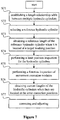
- Figure 7 is a flow chart of a control method according to a third embodiment of the present application. As shown in Figure 7 , unlike the second embodiment, this embodiment has a limit position inspection of the hydraulic cylinders added in the self-inspection step, and the control method for the hydraulic control turning system of the generator rotor includes the following steps S71 to S77.
- S71 may include establishing a length relationship table between multiple hydraulic cylinders.
- the dimension relationships between the multiple hydraulic cylinders of the hydraulic control turning system are fixed, and this is based on the fact that for the hydraulic cylinders employed in each set of hydraulic control turning system, length relationships, i.e., difference relationships, are determined theoretically.
- the length relationship table may show the dimension relationships respectively established between a reference hydraulic cylinder and other hydraulic cylinders, or may show dimension relationships respectively established between the hydraulic cylinders.
- S72 may include selecting a reference hydraulic cylinder.
- the third hydraulic cylinder 33 that is substantially horizontal may be selected as the reference hydraulic cylinder.
- the hydraulic cylinder In a free state, the hydraulic cylinder has almost no load, while other hydraulic cylinders have loads of self-weight of the driving units, and an optimal accuracy may be obtained by taking the third hydraulic cylinder 33 as a control reference.
- the attitude angles of hydraulic cylinders in different systems have different overall design requirements.
- a hydraulic cylinder of the hydraulic cylinders having a smallest angle with respect to the horizontal plane is taken as the reference hydraulic cylinder, which just meets the requirement for avoiding the effect of self-weight load as mentioned above.
- S73 may include obtaining a reference length of the reference hydraulic cylinder when it is located at a target working position.
- the third hydraulic cylinder 33 that is substantially horizontal may be selected as the reference hydraulic cylinder. In a free state, the hydraulic cylinder has almost no load.
- the "target working position” described herein is a position where the corresponding turning pin of the reference hydraulic cylinder is inserted into the fitting hole.
- S74 may include performing a limit position inspection for the hydraulic cylinders.
- the limit position inspection is performed for each of the multiple hydraulic cylinders to verify that each hydraulic cylinder can move to its own limit position.
- the limit position inspection here may determine that the turning system meets a second starting condition, that is, confirm that the hydraulic cylinders themselves have a good starting basis, by obtaining lengths of the hydraulic cylinders at the limit positions.
- S75 may include performing a function inspection of movement execution module, which is specifically similar to the first embodiment.
- the execution order of the function inspection of the movement execution modules and the limit position inspection for the hydraulic cylinders is not specifically limited herein. After it is determined through the limit position inspection that the second starting condition is met, the function inspection of the movement execution modules is performed, which may obviously ensure the reliability of the turning operation to the utmost extent.
- the movement may also include moving clockwise to the limit position and/or moving counterclockwise to the limit position.
- the movement direction of the limit position inspection and the movement direction of the function inspection of the movement execution modules should be consistent with each other.
- the limit position inspection and the function inspection of the movement execution modules are respectively operated in the sequence that the hydraulic cylinders respectively move clockwise first, then move counterclockwise, which is described in detail as follows.
- the five driving hydraulic cylinders move counterclockwise one by one to the limit positions of the hydraulic cylinders.
- the five driving hydraulic cylinders move clockwise one by one to the limit positions of the hydraulic cylinders.
- limit position inspection and the function inspection of the movement execution module may also be designed such that the cylinders respectively move clockwise first, then move counterclockwise, which may also realize the above self-inspection operation.
- S76 may include obtaining current lengths of the five hydraulic cylinders when the cylinders are located at the error correction positions.
- the turning system enters a turning operation state.
- the error correction positions are working positions where the above hydraulic cylinders are located when the hydraulic cylinders complete at least one driving stroke.
- S77 may include correcting and adjusting.
- the lengths of the other hydraulic cylinders corresponding to the next driving stroke are adjusted to conform to the length relationship table.
- Figure 8 is a unit block diagram of a control device for a hydraulic control turning system of a generator rotor according to an embodiment of the present application.
- the control device for the hydraulic control turning system of the generator rotor includes a first detecting unit 81, a storage unit 82 and a control unit 83.
- the first detecting unit 81 acquires the current lengths of the multiple hydraulic cylinders when the multiple hydraulic cylinders are located at the error correction positions.
- the first detecting unit 81 may acquire signals by a sensor. Since the specific structure principle of the sensor is not the invention point of the present application, those skilled in the art may make a selection based on the concept of the present application, and details of the sensor are not described herein again.
- the storage unit 82 stores the length relationship table between multiple hydraulic cylinders of the hydraulic control turning system, and the relationship table may be preset based on the hydraulic cylinder parameters of a specific turning system.
- control unit 83 is capable of adjusting the lengths of the other hydraulic cylinders corresponding to the next driving stroke to conform to the length relationship table, with the current length of the reference hydraulic cylinder as a determining reference.
- the accumulated dimension error between the hydraulic cylinders may be dynamically corrected during the turning operation, thereby ensuring that the turning pins are accurately aligned with the pin holes in the generator, and the corresponding turning operation is performed after the generator set is locked.
- the first detecting unit 81 further acquires a reference length of the reference cylinder when it is located at the target working position, so as to allow the control unit 83 to issue specific instructions based on the reference length and the length relationship table and control the multiple hydraulic cylinders to perform a function inspection of the movement execution modules in sequence, that is, to move to the limit turning positions, to insert the turning pins into the fitting holes or to pull the turning pins out of the fitting holes.
- the control unit 83 may further issue specific instructions to control the multiple hydraulic cylinders to respectively perform a limit position inspection, that is, to move to the limit positions of the hydraulic cylinders.
- the control unit 83 may be provided independently, or may adopt a control unit of a control system of the whole set.
- control device may further include a second detecting unit 84 to acquire insertion signals and pullout signals of the turning pins, and output the signals to the control unit to determine that the turning system meets the first starting condition.
- second detecting unit 84 may also acquire signals by a sensor.
- the first detecting unit 81 which acquires the lengths of the hydraulic cylinders, may also acquire the limit positions of the multiple hydraulic cylinders and the limit positions of the turning, and output the limit positions to the control unit to determine that the turning system meets the second starting condition.
Landscapes
- Engineering & Computer Science (AREA)
- Mechanical Engineering (AREA)
- Sustainable Development (AREA)
- Sustainable Energy (AREA)
- Chemical & Material Sciences (AREA)
- Combustion & Propulsion (AREA)
- Life Sciences & Earth Sciences (AREA)
- General Engineering & Computer Science (AREA)
- Physics & Mathematics (AREA)
- Fluid Mechanics (AREA)
- Wind Motors (AREA)
- Hydraulic Motors (AREA)
- Actuator (AREA)
- Manufacture Of Motors, Generators (AREA)
Applications Claiming Priority (2)
| Application Number | Priority Date | Filing Date | Title |
|---|---|---|---|
| CN201711464107.1A CN109973303B (zh) | 2017-12-28 | 2017-12-28 | 发电机转子液控盘车系统的控制方法及装置 |
| PCT/CN2018/083873 WO2019127997A1 (zh) | 2017-12-28 | 2018-04-20 | 发电机转子液控盘车系统的控制方法及装置 |
Publications (3)
| Publication Number | Publication Date |
|---|---|
| EP3530889A1 true EP3530889A1 (de) | 2019-08-28 |
| EP3530889A4 EP3530889A4 (de) | 2019-08-28 |
| EP3530889B1 EP3530889B1 (de) | 2021-05-26 |
Family
ID=64604594
Family Applications (1)
| Application Number | Title | Priority Date | Filing Date |
|---|---|---|---|
| EP18769020.1A Active EP3530889B1 (de) | 2017-12-28 | 2018-04-20 | Steuerungsverfahren und -vorrichtung |
Country Status (6)
| Country | Link |
|---|---|
| US (1) | US11162473B2 (de) |
| EP (1) | EP3530889B1 (de) |
| CN (1) | CN109973303B (de) |
| AU (1) | AU2018229463B2 (de) |
| ES (1) | ES2885224T3 (de) |
| WO (1) | WO2019127997A1 (de) |
Families Citing this family (1)
| Publication number | Priority date | Publication date | Assignee | Title |
|---|---|---|---|---|
| CN109973327B (zh) * | 2017-12-28 | 2020-03-03 | 江苏金风科技有限公司 | 发电机转子液控盘车系统的自检方法及装置 |
Family Cites Families (19)
| Publication number | Priority date | Publication date | Assignee | Title |
|---|---|---|---|---|
| DK1659286T3 (da) * | 2004-11-18 | 2009-02-23 | Eickhoff Maschinenfabrik Gmbh | Törneindretning til at drive en drivmotor og transmission i et vindkraftanlæg |
| DE102005026697A1 (de) | 2005-06-09 | 2006-12-14 | Siemens Ag | Passive Hydrauliksteuerung mit Positionskorrektur durch richtungsgesteuerten Ölaustausch |
| TW201100635A (en) | 2009-06-30 | 2011-01-01 | Atomic Energy Council | Blade inclination angle driving device for wind-powered electricity generation device |
| NO20092984A1 (no) * | 2009-09-11 | 2011-02-14 | Blaaster Wind Tech As | Vindturbin |
| CN201575124U (zh) | 2009-12-07 | 2010-09-08 | 桐庐中北机械科技有限公司 | 一种可实现无极调速液压驱动的传动装置 |
| JP4953395B2 (ja) | 2010-02-15 | 2012-06-13 | 株式会社日本製鋼所 | 回転位置調整機構および回転位置調整方法 |
| DE102011017801B8 (de) | 2011-04-29 | 2013-05-08 | Wobben Properties Gmbh | Windenergieanlage mit einer Mehrzahl von Verschiebeeinheiten zur Montage oder Demontage von Rotorblättern und Verfahren hierzu |
| CN202391864U (zh) | 2011-12-20 | 2012-08-22 | 中联重科股份有限公司 | 伸缩缸的行程检测装置和伸缩缸 |
| CN202451374U (zh) * | 2012-02-15 | 2012-09-26 | 三一电气有限责任公司 | 一种盘车装置及风机 |
| DK2767708T3 (en) | 2013-02-13 | 2015-08-10 | Siemens Ag | Turning device for rotating the rotatable part of a wind turbine |
| WO2014167732A1 (ja) * | 2013-04-12 | 2014-10-16 | 株式会社小松製作所 | 油圧シリンダのストローク動作校正制御装置及び油圧シリンダのストローク動作校正制御方法 |
| DE102014207712A1 (de) | 2013-06-24 | 2014-12-24 | Siemens Aktiengesellschaft | Vorrichtung und Verfahren zum Drehen eines Rotors einer Windkraftanlage |
| WO2014206482A1 (en) | 2013-06-28 | 2014-12-31 | Aktiebolaget Skf | Tool for temporarily connecting a hub element and a blade of a wind turbine |
| CN103470321B (zh) * | 2013-09-03 | 2015-04-01 | 国家电网公司 | 一种汽轮发电机组液压缸盘车装置 |
| GB201320191D0 (en) * | 2013-11-15 | 2014-01-01 | Ricardo Uk Ltd | Wind turbine |
| DE102014208468A1 (de) * | 2014-05-06 | 2015-11-12 | Wobben Properties Gmbh | Azimutverstellung einer Windenergieanlage |
| CN105370414B (zh) | 2014-08-26 | 2017-01-25 | 国家电网公司 | 一种基于燃气轮机液压盘车装置的控制系统 |
| CN106438197B (zh) * | 2016-12-12 | 2019-02-12 | 江苏金风科技有限公司 | 用于转动风力发电机转子的装置、方法及风力发电机组 |
| CN106762438B (zh) * | 2016-12-29 | 2020-11-24 | 江苏金风科技有限公司 | 用于转动风力发电机组转子的装置及方法 |
-
2017
- 2017-12-28 CN CN201711464107.1A patent/CN109973303B/zh active Active
-
2018
- 2018-04-20 WO PCT/CN2018/083873 patent/WO2019127997A1/zh not_active Ceased
- 2018-04-20 US US16/086,005 patent/US11162473B2/en active Active
- 2018-04-20 AU AU2018229463A patent/AU2018229463B2/en active Active
- 2018-04-20 ES ES18769020T patent/ES2885224T3/es active Active
- 2018-04-20 EP EP18769020.1A patent/EP3530889B1/de active Active
Also Published As
| Publication number | Publication date |
|---|---|
| EP3530889B1 (de) | 2021-05-26 |
| AU2018229463A1 (en) | 2019-07-18 |
| ES2885224T3 (es) | 2021-12-13 |
| AU2018229463B2 (en) | 2020-01-23 |
| US11162473B2 (en) | 2021-11-02 |
| EP3530889A4 (de) | 2019-08-28 |
| CN109973303B (zh) | 2020-05-12 |
| WO2019127997A1 (zh) | 2019-07-04 |
| US20200392941A1 (en) | 2020-12-17 |
| CN109973303A (zh) | 2019-07-05 |
Similar Documents
| Publication | Publication Date | Title |
|---|---|---|
| US3714660A (en) | Antenna mounting structure | |
| DK3064309T3 (en) | Positioning apparatus and method for precisely mutually aligning a first and a second tubular member | |
| EP2924284A1 (de) | Gegengewicht einer Windturbinennabe | |
| EP3540215B1 (de) | Rotordrehungsteuerungssystem und -steuerungsverfahren für windturbine | |
| EP3530889B1 (de) | Steuerungsverfahren und -vorrichtung | |
| US10989170B2 (en) | Control method for rotor turning device, computer program product, computer readable storage medium, control device, and rotor turning system | |
| CN117184438B (zh) | 一种飞行器机翼机身装配控制方法 | |
| CN110529341B (zh) | 一种新能源供能用可调节发电装置 | |
| EP3564527B1 (de) | Selbstprüfungsverfahren und -vorrichtung für hydraulisch gesteuertes generatorrotordrehsystem | |
| CN109099834A (zh) | 一种螺栓孔对准检测的装置 | |
| CN120505942A (zh) | 一种光伏沉桩方法及光伏板安装方法 | |
| US12091136B2 (en) | Underwater penetration system for offshore wind power and cooperative operation method thereof | |
| CN217084652U (zh) | 一种视觉检测工业相机定位调整装置 | |
| CN114772451B (zh) | Tbm主机吊装用吊具及吊装装置和方法 | |
| EP3926251A1 (de) | Verfahren und system zur steuerung einer horizontalen einachsigen solaranlage | |
| CN110340458A (zh) | 一种具有控制顶紧力度的机加工用辅助台架 | |
| LU500772B1 (en) | Lifting and Locking Device for Pile Leg of Jack-up Offshore Platform | |
| CN119083438B (zh) | 自升式海上稳桩平台抱桩器的工作方法 | |
| CN115864967B (zh) | 一种光伏组件高度调节装置 | |
| CN211340734U (zh) | 一种海上嵌岩小平台 | |
| CN119347829B (zh) | 用于内外筒体装配的内撑式末端执行器及装配方法 | |
| CN219732071U (zh) | 一种挡土墙 | |
| CN217943266U (zh) | 一种轴系校中光仪器定位装置 | |
| CN110757151B (zh) | 一种谐波减速器自动装配系统及其控制方法 | |
| CN117566434A (zh) | 一种用于快速堆垛机的调试方法 |
Legal Events
| Date | Code | Title | Description |
|---|---|---|---|
| STAA | Information on the status of an ep patent application or granted ep patent |
Free format text: STATUS: UNKNOWN |
|
| STAA | Information on the status of an ep patent application or granted ep patent |
Free format text: STATUS: THE INTERNATIONAL PUBLICATION HAS BEEN MADE |
|
| PUAI | Public reference made under article 153(3) epc to a published international application that has entered the european phase |
Free format text: ORIGINAL CODE: 0009012 |
|
| STAA | Information on the status of an ep patent application or granted ep patent |
Free format text: STATUS: REQUEST FOR EXAMINATION WAS MADE |
|
| 17P | Request for examination filed |
Effective date: 20180925 |
|
| A4 | Supplementary search report drawn up and despatched |
Effective date: 20190417 |
|
| AK | Designated contracting states |
Kind code of ref document: A1 Designated state(s): AL AT BE BG CH CY CZ DE DK EE ES FI FR GB GR HR HU IE IS IT LI LT LU LV MC MK MT NL NO PL PT RO RS SE SI SK SM TR |
|
| AX | Request for extension of the european patent |
Extension state: BA ME |
|
| STAA | Information on the status of an ep patent application or granted ep patent |
Free format text: STATUS: EXAMINATION IS IN PROGRESS |
|
| 17Q | First examination report despatched |
Effective date: 20190910 |
|
| GRAP | Despatch of communication of intention to grant a patent |
Free format text: ORIGINAL CODE: EPIDOSNIGR1 |
|
| STAA | Information on the status of an ep patent application or granted ep patent |
Free format text: STATUS: GRANT OF PATENT IS INTENDED |
|
| DAV | Request for validation of the european patent (deleted) | ||
| DAX | Request for extension of the european patent (deleted) | ||
| INTG | Intention to grant announced |
Effective date: 20200707 |
|
| GRAJ | Information related to disapproval of communication of intention to grant by the applicant or resumption of examination proceedings by the epo deleted |
Free format text: ORIGINAL CODE: EPIDOSDIGR1 |
|
| STAA | Information on the status of an ep patent application or granted ep patent |
Free format text: STATUS: EXAMINATION IS IN PROGRESS |
|
| INTC | Intention to grant announced (deleted) | ||
| GRAP | Despatch of communication of intention to grant a patent |
Free format text: ORIGINAL CODE: EPIDOSNIGR1 |
|
| STAA | Information on the status of an ep patent application or granted ep patent |
Free format text: STATUS: GRANT OF PATENT IS INTENDED |
|
| INTG | Intention to grant announced |
Effective date: 20201116 |
|
| GRAS | Grant fee paid |
Free format text: ORIGINAL CODE: EPIDOSNIGR3 |
|
| GRAA | (expected) grant |
Free format text: ORIGINAL CODE: 0009210 |
|
| STAA | Information on the status of an ep patent application or granted ep patent |
Free format text: STATUS: THE PATENT HAS BEEN GRANTED |
|
| RIN1 | Information on inventor provided before grant (corrected) |
Inventor name: CHENG, WEI Inventor name: LI, HONGFENG Inventor name: LI, PENGYANG Inventor name: ZHAI, ENDI Inventor name: ZHANG, XINGANG Inventor name: LI, YE |
|
| AK | Designated contracting states |
Kind code of ref document: B1 Designated state(s): AL AT BE BG CH CY CZ DE DK EE ES FI FR GB GR HR HU IE IS IT LI LT LU LV MC MK MT NL NO PL PT RO RS SE SI SK SM TR |
|
| REG | Reference to a national code |
Ref country code: GB Ref legal event code: FG4D |
|
| REG | Reference to a national code |
Ref country code: CH Ref legal event code: EP |
|
| REG | Reference to a national code |
Ref country code: DE Ref legal event code: R096 Ref document number: 602018017788 Country of ref document: DE |
|
| REG | Reference to a national code |
Ref country code: AT Ref legal event code: REF Ref document number: 1396422 Country of ref document: AT Kind code of ref document: T Effective date: 20210615 |
|
| REG | Reference to a national code |
Ref country code: IE Ref legal event code: FG4D |
|
| REG | Reference to a national code |
Ref country code: LT Ref legal event code: MG9D |
|
| REG | Reference to a national code |
Ref country code: AT Ref legal event code: MK05 Ref document number: 1396422 Country of ref document: AT Kind code of ref document: T Effective date: 20210526 |
|
| PG25 | Lapsed in a contracting state [announced via postgrant information from national office to epo] |
Ref country code: FI Free format text: LAPSE BECAUSE OF FAILURE TO SUBMIT A TRANSLATION OF THE DESCRIPTION OR TO PAY THE FEE WITHIN THE PRESCRIBED TIME-LIMIT Effective date: 20210526 Ref country code: HR Free format text: LAPSE BECAUSE OF FAILURE TO SUBMIT A TRANSLATION OF THE DESCRIPTION OR TO PAY THE FEE WITHIN THE PRESCRIBED TIME-LIMIT Effective date: 20210526 Ref country code: LT Free format text: LAPSE BECAUSE OF FAILURE TO SUBMIT A TRANSLATION OF THE DESCRIPTION OR TO PAY THE FEE WITHIN THE PRESCRIBED TIME-LIMIT Effective date: 20210526 Ref country code: BG Free format text: LAPSE BECAUSE OF FAILURE TO SUBMIT A TRANSLATION OF THE DESCRIPTION OR TO PAY THE FEE WITHIN THE PRESCRIBED TIME-LIMIT Effective date: 20210826 Ref country code: AT Free format text: LAPSE BECAUSE OF FAILURE TO SUBMIT A TRANSLATION OF THE DESCRIPTION OR TO PAY THE FEE WITHIN THE PRESCRIBED TIME-LIMIT Effective date: 20210526 |
|
| REG | Reference to a national code |
Ref country code: NL Ref legal event code: MP Effective date: 20210526 |
|
| REG | Reference to a national code |
Ref country code: GR Ref legal event code: EP Ref document number: 20210402039 Country of ref document: GR Effective date: 20211013 |
|
| PG25 | Lapsed in a contracting state [announced via postgrant information from national office to epo] |
Ref country code: PT Free format text: LAPSE BECAUSE OF FAILURE TO SUBMIT A TRANSLATION OF THE DESCRIPTION OR TO PAY THE FEE WITHIN THE PRESCRIBED TIME-LIMIT Effective date: 20210927 Ref country code: SE Free format text: LAPSE BECAUSE OF FAILURE TO SUBMIT A TRANSLATION OF THE DESCRIPTION OR TO PAY THE FEE WITHIN THE PRESCRIBED TIME-LIMIT Effective date: 20210526 Ref country code: RS Free format text: LAPSE BECAUSE OF FAILURE TO SUBMIT A TRANSLATION OF THE DESCRIPTION OR TO PAY THE FEE WITHIN THE PRESCRIBED TIME-LIMIT Effective date: 20210526 Ref country code: NO Free format text: LAPSE BECAUSE OF FAILURE TO SUBMIT A TRANSLATION OF THE DESCRIPTION OR TO PAY THE FEE WITHIN THE PRESCRIBED TIME-LIMIT Effective date: 20210826 Ref country code: LV Free format text: LAPSE BECAUSE OF FAILURE TO SUBMIT A TRANSLATION OF THE DESCRIPTION OR TO PAY THE FEE WITHIN THE PRESCRIBED TIME-LIMIT Effective date: 20210526 Ref country code: PL Free format text: LAPSE BECAUSE OF FAILURE TO SUBMIT A TRANSLATION OF THE DESCRIPTION OR TO PAY THE FEE WITHIN THE PRESCRIBED TIME-LIMIT Effective date: 20210526 Ref country code: IS Free format text: LAPSE BECAUSE OF FAILURE TO SUBMIT A TRANSLATION OF THE DESCRIPTION OR TO PAY THE FEE WITHIN THE PRESCRIBED TIME-LIMIT Effective date: 20210926 |
|
| REG | Reference to a national code |
Ref country code: ES Ref legal event code: FG2A Ref document number: 2885224 Country of ref document: ES Kind code of ref document: T3 Effective date: 20211213 |
|
| PG25 | Lapsed in a contracting state [announced via postgrant information from national office to epo] |
Ref country code: NL Free format text: LAPSE BECAUSE OF FAILURE TO SUBMIT A TRANSLATION OF THE DESCRIPTION OR TO PAY THE FEE WITHIN THE PRESCRIBED TIME-LIMIT Effective date: 20210526 |
|
| PG25 | Lapsed in a contracting state [announced via postgrant information from national office to epo] |
Ref country code: SM Free format text: LAPSE BECAUSE OF FAILURE TO SUBMIT A TRANSLATION OF THE DESCRIPTION OR TO PAY THE FEE WITHIN THE PRESCRIBED TIME-LIMIT Effective date: 20210526 Ref country code: RO Free format text: LAPSE BECAUSE OF FAILURE TO SUBMIT A TRANSLATION OF THE DESCRIPTION OR TO PAY THE FEE WITHIN THE PRESCRIBED TIME-LIMIT Effective date: 20210526 Ref country code: DK Free format text: LAPSE BECAUSE OF FAILURE TO SUBMIT A TRANSLATION OF THE DESCRIPTION OR TO PAY THE FEE WITHIN THE PRESCRIBED TIME-LIMIT Effective date: 20210526 Ref country code: CZ Free format text: LAPSE BECAUSE OF FAILURE TO SUBMIT A TRANSLATION OF THE DESCRIPTION OR TO PAY THE FEE WITHIN THE PRESCRIBED TIME-LIMIT Effective date: 20210526 Ref country code: SK Free format text: LAPSE BECAUSE OF FAILURE TO SUBMIT A TRANSLATION OF THE DESCRIPTION OR TO PAY THE FEE WITHIN THE PRESCRIBED TIME-LIMIT Effective date: 20210526 Ref country code: EE Free format text: LAPSE BECAUSE OF FAILURE TO SUBMIT A TRANSLATION OF THE DESCRIPTION OR TO PAY THE FEE WITHIN THE PRESCRIBED TIME-LIMIT Effective date: 20210526 |
|
| REG | Reference to a national code |
Ref country code: DE Ref legal event code: R097 Ref document number: 602018017788 Country of ref document: DE |
|
| PLBE | No opposition filed within time limit |
Free format text: ORIGINAL CODE: 0009261 |
|
| STAA | Information on the status of an ep patent application or granted ep patent |
Free format text: STATUS: NO OPPOSITION FILED WITHIN TIME LIMIT |
|
| 26N | No opposition filed |
Effective date: 20220301 |
|
| PG25 | Lapsed in a contracting state [announced via postgrant information from national office to epo] |
Ref country code: IS Free format text: LAPSE BECAUSE OF FAILURE TO SUBMIT A TRANSLATION OF THE DESCRIPTION OR TO PAY THE FEE WITHIN THE PRESCRIBED TIME-LIMIT Effective date: 20210926 Ref country code: AL Free format text: LAPSE BECAUSE OF FAILURE TO SUBMIT A TRANSLATION OF THE DESCRIPTION OR TO PAY THE FEE WITHIN THE PRESCRIBED TIME-LIMIT Effective date: 20210526 |
|
| REG | Reference to a national code |
Ref country code: DE Ref legal event code: R119 Ref document number: 602018017788 Country of ref document: DE |
|
| REG | Reference to a national code |
Ref country code: CH Ref legal event code: PL |
|
| GBPC | Gb: european patent ceased through non-payment of renewal fee |
Effective date: 20220420 |
|
| REG | Reference to a national code |
Ref country code: BE Ref legal event code: MM Effective date: 20220430 |
|
| PG25 | Lapsed in a contracting state [announced via postgrant information from national office to epo] |
Ref country code: MC Free format text: LAPSE BECAUSE OF FAILURE TO SUBMIT A TRANSLATION OF THE DESCRIPTION OR TO PAY THE FEE WITHIN THE PRESCRIBED TIME-LIMIT Effective date: 20210526 Ref country code: LU Free format text: LAPSE BECAUSE OF NON-PAYMENT OF DUE FEES Effective date: 20220420 Ref country code: LI Free format text: LAPSE BECAUSE OF NON-PAYMENT OF DUE FEES Effective date: 20220430 Ref country code: GB Free format text: LAPSE BECAUSE OF NON-PAYMENT OF DUE FEES Effective date: 20220420 Ref country code: FR Free format text: LAPSE BECAUSE OF NON-PAYMENT OF DUE FEES Effective date: 20220430 Ref country code: DE Free format text: LAPSE BECAUSE OF NON-PAYMENT OF DUE FEES Effective date: 20221103 Ref country code: CH Free format text: LAPSE BECAUSE OF NON-PAYMENT OF DUE FEES Effective date: 20220430 |
|
| PG25 | Lapsed in a contracting state [announced via postgrant information from national office to epo] |
Ref country code: BE Free format text: LAPSE BECAUSE OF NON-PAYMENT OF DUE FEES Effective date: 20220430 |
|
| PG25 | Lapsed in a contracting state [announced via postgrant information from national office to epo] |
Ref country code: IE Free format text: LAPSE BECAUSE OF NON-PAYMENT OF DUE FEES Effective date: 20220420 |
|
| PG25 | Lapsed in a contracting state [announced via postgrant information from national office to epo] |
Ref country code: HU Free format text: LAPSE BECAUSE OF FAILURE TO SUBMIT A TRANSLATION OF THE DESCRIPTION OR TO PAY THE FEE WITHIN THE PRESCRIBED TIME-LIMIT; INVALID AB INITIO Effective date: 20180420 |
|
| PG25 | Lapsed in a contracting state [announced via postgrant information from national office to epo] |
Ref country code: MK Free format text: LAPSE BECAUSE OF FAILURE TO SUBMIT A TRANSLATION OF THE DESCRIPTION OR TO PAY THE FEE WITHIN THE PRESCRIBED TIME-LIMIT Effective date: 20210526 Ref country code: CY Free format text: LAPSE BECAUSE OF FAILURE TO SUBMIT A TRANSLATION OF THE DESCRIPTION OR TO PAY THE FEE WITHIN THE PRESCRIBED TIME-LIMIT Effective date: 20210526 |
|
| PG25 | Lapsed in a contracting state [announced via postgrant information from national office to epo] |
Ref country code: MT Free format text: LAPSE BECAUSE OF FAILURE TO SUBMIT A TRANSLATION OF THE DESCRIPTION OR TO PAY THE FEE WITHIN THE PRESCRIBED TIME-LIMIT Effective date: 20210526 |
|
| PGFP | Annual fee paid to national office [announced via postgrant information from national office to epo] |
Ref country code: GR Payment date: 20250318 Year of fee payment: 8 |
|
| PGFP | Annual fee paid to national office [announced via postgrant information from national office to epo] |
Ref country code: IT Payment date: 20250320 Year of fee payment: 8 |
|
| PGFP | Annual fee paid to national office [announced via postgrant information from national office to epo] |
Ref country code: ES Payment date: 20250508 Year of fee payment: 8 |
|
| PGFP | Annual fee paid to national office [announced via postgrant information from national office to epo] |
Ref country code: TR Payment date: 20250409 Year of fee payment: 8 |