EP3530525B1 - Automotive vehicle - Google Patents
Automotive vehicle Download PDFInfo
- Publication number
- EP3530525B1 EP3530525B1 EP17873219.4A EP17873219A EP3530525B1 EP 3530525 B1 EP3530525 B1 EP 3530525B1 EP 17873219 A EP17873219 A EP 17873219A EP 3530525 B1 EP3530525 B1 EP 3530525B1
- Authority
- EP
- European Patent Office
- Prior art keywords
- vehicle body
- body shell
- flat
- conductive core
- cable
- Prior art date
- Legal status (The legal status is an assumption and is not a legal conclusion. Google has not performed a legal analysis and makes no representation as to the accuracy of the status listed.)
- Active
Links
Images



Classifications
-
- B—PERFORMING OPERATIONS; TRANSPORTING
- B60—VEHICLES IN GENERAL
- B60R—VEHICLES, VEHICLE FITTINGS, OR VEHICLE PARTS, NOT OTHERWISE PROVIDED FOR
- B60R16/00—Electric or fluid circuits specially adapted for vehicles and not otherwise provided for; Arrangement of elements of electric or fluid circuits specially adapted for vehicles and not otherwise provided for
- B60R16/02—Electric or fluid circuits specially adapted for vehicles and not otherwise provided for; Arrangement of elements of electric or fluid circuits specially adapted for vehicles and not otherwise provided for electric constitutive elements
- B60R16/0207—Wire harnesses
- B60R16/0215—Protecting, fastening and routing means therefor
-
- B—PERFORMING OPERATIONS; TRANSPORTING
- B60—VEHICLES IN GENERAL
- B60R—VEHICLES, VEHICLE FITTINGS, OR VEHICLE PARTS, NOT OTHERWISE PROVIDED FOR
- B60R16/00—Electric or fluid circuits specially adapted for vehicles and not otherwise provided for; Arrangement of elements of electric or fluid circuits specially adapted for vehicles and not otherwise provided for
- B60R16/02—Electric or fluid circuits specially adapted for vehicles and not otherwise provided for; Arrangement of elements of electric or fluid circuits specially adapted for vehicles and not otherwise provided for electric constitutive elements
-
- B—PERFORMING OPERATIONS; TRANSPORTING
- B60—VEHICLES IN GENERAL
- B60R—VEHICLES, VEHICLE FITTINGS, OR VEHICLE PARTS, NOT OTHERWISE PROVIDED FOR
- B60R16/00—Electric or fluid circuits specially adapted for vehicles and not otherwise provided for; Arrangement of elements of electric or fluid circuits specially adapted for vehicles and not otherwise provided for
- B60R16/02—Electric or fluid circuits specially adapted for vehicles and not otherwise provided for; Arrangement of elements of electric or fluid circuits specially adapted for vehicles and not otherwise provided for electric constitutive elements
- B60R16/03—Electric or fluid circuits specially adapted for vehicles and not otherwise provided for; Arrangement of elements of electric or fluid circuits specially adapted for vehicles and not otherwise provided for electric constitutive elements for supply of electrical power to vehicle subsystems or for
- B60R16/033—Electric or fluid circuits specially adapted for vehicles and not otherwise provided for; Arrangement of elements of electric or fluid circuits specially adapted for vehicles and not otherwise provided for electric constitutive elements for supply of electrical power to vehicle subsystems or for characterised by the use of electrical cells or batteries
-
- H—ELECTRICITY
- H01—ELECTRIC ELEMENTS
- H01B—CABLES; CONDUCTORS; INSULATORS; SELECTION OF MATERIALS FOR THEIR CONDUCTIVE, INSULATING OR DIELECTRIC PROPERTIES
- H01B7/00—Insulated conductors or cables characterised by their form
- H01B7/0009—Details relating to the conductive cores
-
- H—ELECTRICITY
- H01—ELECTRIC ELEMENTS
- H01B—CABLES; CONDUCTORS; INSULATORS; SELECTION OF MATERIALS FOR THEIR CONDUCTIVE, INSULATING OR DIELECTRIC PROPERTIES
- H01B7/00—Insulated conductors or cables characterised by their form
- H01B7/04—Flexible cables, conductors, or cords, e.g. trailing cables
-
- H—ELECTRICITY
- H01—ELECTRIC ELEMENTS
- H01B—CABLES; CONDUCTORS; INSULATORS; SELECTION OF MATERIALS FOR THEIR CONDUCTIVE, INSULATING OR DIELECTRIC PROPERTIES
- H01B7/00—Insulated conductors or cables characterised by their form
- H01B7/08—Flat or ribbon cables
-
- H—ELECTRICITY
- H01—ELECTRIC ELEMENTS
- H01B—CABLES; CONDUCTORS; INSULATORS; SELECTION OF MATERIALS FOR THEIR CONDUCTIVE, INSULATING OR DIELECTRIC PROPERTIES
- H01B1/00—Conductors or conductive bodies characterised by the conductive materials; Selection of materials as conductors
- H01B1/02—Conductors or conductive bodies characterised by the conductive materials; Selection of materials as conductors mainly consisting of metals or alloys
Definitions
- the present invention relates to an automotive vehicle.
- the existing automotive vehicles generally include a vehicle body shell, a plug, a power supply, and a power supply cable configured to connect the power supply and the plug.
- the plug and power supply are respectively located in the front end and the back end of the body shell of the vehicle.
- the commonly used power supply cables have a round cross section. Owing to the round cross section, the forces applied to different points of the same circumference are isotropous. As a result, it is hard to bend the cable because of a deformation difficulty under an action of an external force, thus the difficulty in installation is increased.
- a number of fasteners are required to fix the power supply cable having round cross section on the vehicle body.
- a fastener is required to fix the cable. In this case, not only the installation workload is increased, but also it is not favorable for lowering the installation cost.
- the existing power supply cable generally extend along the vehicle body shell.
- the installation stability of the power supply cable will be greatly affected.
- the conductive core of the existing power supply cable is made of copper which is expensive and heavy, it is not only unhelpful in lowering the material cost and transportation cost, but also cannot satisfy the requirements for pursuing the weight-reduced vehicle by people.
- the automotive vehicle of the present invention is not only required to reduce the probability of abusing the cable wires, ensure a reasonable use of the wires, and lower the installation cost, but also to effectively ensure the installation stability of the cables, reduce the difficulty in installation of power supply cables, reduce the installation workload, lower the cable material cost and transportation cost, and satisfy the requirements for pursuing the weight-reduced vehicle by people.
- the present invention uses the following technical solutions.
- An automotive vehicle includes a vehicle body shell, a power supply, and an in-car plug or junction device.
- the power supply is connected to the in-car plug or junction device partially or completely by flat cables.
- the flat cables extend along the vehicle body shell, and a distance between the flat cables and the vehicle body shell is less than or equal to 300mm.
- Each of the flat cables comprises a solid conductive core with a flat cross section and a flexible insulation layer wrapping over the solid conductive core.
- the solid conductive core is made of aluminium, and the solid aluminum conductive core has a ripple-shaped cross section.
- the flat cables are fixed on the vehicle body shell by a plurality of spaced-apart fasteners.
- An interval distance between two adjacent fasteners is 10-200 cm.
- a flat cable for an automotive vehicle having a vehicle body shell, a power supply, and an in-car plug or junction device, wherein the flat cable connects the power supply to the in-car plug or junction device partially or completely, and the flat cable extends along the vehicle body shell, wherein each of the flat cables comprises a solid conductive core with a flat cross section and a flexible insulation layer wrapping over the solid conductive core and a distance between the flat cables and the vehicle body shell is less than or equal to 300mm; characterized in that the solid conductive core is made of aluminium, and the solid aluminum conductive core has a ripple-shaped cross section.
- the present invention has the following advantages. 1.
- existing round cables of the automotive vehicles are partially or completely replaced with the flat cables. Owing to the flat cross section of the flat cable, the forces applied to the points on the flat cable are anisotropic, so the flat cables are easy to bend when being installed on the vehicle body shell, thereby greatly reducing the installation difficulty, simplifying the installation process, and reducing the installation workload.
- the flat cable is installed at a location less than or equal to 300 mm from the vehicle body shell, which is a location relatively close to the profile of the vehicle body shell.
- Extending the flat cable along the vehicle body shell is helpful in reducing the installation space of the flat cables in the vehicle body shell, so as to satisfy the requirement for simplifying the installation space by the people.
- the existing copper core is replaced with a solid aluminum conductive core (wherein the solid aluminum conductive core may be an aluminum core or an aluminum alloy core).
- the density of aluminum is one third the density of copper.
- the length to diameter ratio of aluminum is merely 1.28 times the length to diameter ratio of copper, while the weight of aluminum material is half the weight of copper material having the same current capacity.
- the weight of the cables can be greatly reduced, which is helpful in reducing the weight of the vehicle.
- the material cost and transportation cost can be reduced, thereby reducing the production cost of the automotive vehicle and improving the performances of the vehicle.
- the flat cables can be installed in a better fit with the profile of the vehicle body shell, which is favorable in reducing the installation space and installation cost.
- the use of the flat cable not only can firmly fix the flat cables on the vehicle body shell but also can greatly reduce the use amount of the fasteners, thereby remarkably reducing the installation workload and reducing the installation cost and production cost of the automotive vehicles.
- Figs. 1-9 The reference designators in Figs. 1-9 are described below: 1. vehicle body shell; 2. plug; 3. power supply; 4. flat cable; 41. solid aluminum conductive core; 42. flexible insulation layer; 5. chamfer; 6a. bent portion; 6b. bent portion; 6c. bent portion; 6e. bent portion; 6f. bent portion; ⁇ . bending angle; ⁇ . bending angle; ⁇ . bending angle; 7. fastener; H. the distance between the flat cable and the vehicle body shell.
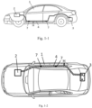
- Fig. 1-1 is the first diagram showing the wiring structure of the automotive vehicle according to the present invention.
- the automotive vehicle includes the vehicle body shell 1, the power supply 3, the in-car plug or junction device 2, and the flat cables 4 that partially or completely connect the power supply 3 and the plug or junction device 2.
- the plug 2 and the power supply 3 are respectively located at the front end and the back end of the vehicle body 1.
- the flat cables 4 extend along the vehicle body shell 1, and the distance H between the flat cables 4 and vehicle body shell 1 is less than or equal to 300mm.
- existing round cables of the automotive vehicles are replaced partially or completely with the flat cables 4.
- the forces applied to the points on the flat cable are anisotropic, so the flat cables are easy to bend when being installed on the vehicle body shell 1, thereby greatly simplifying the installation process.
- the flat cable is installed at a location less than or equal to 300 mm from the vehicle body shell 1, which is a location relatively close to the profile of the vehicle body shell.
- the probability that the flat cable waggles during the bumping of a vehicle because the flat cable is located far from the vehicle body shell 1 can be effectively reduced, which can facilitate the improvement of the installation stability of the flat cables in vehicles.
- the location is relatively closer to the vehicle body shell 1 compared to other locations, there is only a relatively small increase on the cable consumption in the wiring comparatively, so the material consumption in the cable installation can be reduced, the probability of abusing the cable wires can be reduced, a reasonable use of the cable wires can be ensured, and the installation cost can be reduced.
- extending the flat cable along the vehicle body shell 1 is helpful in reducing the installation space of the flat cables in the vehicle body shell 1, so as to satisfy the requirement for simplifying the installation space by the people.
- the flat cable 4 is fixed on the vehicle body shell 1 by several spaced-apart fasteners, and the interval between two adjacent fasteners 7 is 10 - 200 cm.
- the automotive vehicle of the present invention partially or completely uses the flat cables 4.
- the installation stability of the flat cables is better.
- the distance between two adjacent fasteners is merely 10 - 200 cm, i.e. at every 10 - 200 cm interval along the length direction of the flat cable 4, a fastener 7 is provided.
- the use of the flat cable not only can firmly fix the flat cables 4 on the vehicle body shell 1 to further improve the installation stability of the flat cable 4 on the vehicle body shell 1, but also can reduce the use amount of the fasteners 7, thereby remarkably reducing the installation workload and reducing the installation cost and production cost.
- the distance between the flat cable 4 and the vehicle body shell 1 is 2 - 100 mm. Within the value range, better effects can be obtained in the aspects of reducing the bending times of the flat cables 4, shortening the installation time, reducing the material consumption of the flat cables 4, and improving the installation stability of the flat cables 4 in the vehicle body shell 1.
- Figs. 1-2 and 1-3 are the second and third diagrams showing the wiring structure of the automotive vehicle according to the present invention, and they are the top views of Fig. 1-1 .
- Fig. 1-2 is a structural diagram of an automotive vehicle which completely uses the flat cables for connections
- Fig. 1-3 is a structural diagram of an automotive vehicle which partially uses the flat cables for connections.
- the flat cable 4 includes the flat-shaped solid aluminum conductive core 41 and the flexible insulation layer 42 wrapping over the solid aluminum conductive core 41.
- the existing copper core is replaced with the solid aluminum conductive core 41 (wherein, in the present embodiment, the solid aluminum conductive core 41 may be an aluminum core or an aluminum alloy core).
- the density of aluminum is one third the density of copper.
- the length to diameter ratio of aluminum is merely 1.28 times the length to diameter ratio of copper, while the weight of aluminum material is half the weight of copper material having the same current capacity.
- the weight of the lines can be greatly reduced, which is helpful in reducing the weight of the vehicle.
- the material cost and transportation cost can be reduced, thereby reducing the production cost of the automotive vehicle and satisfying the user's needs.
- the power supply 3 is a storage battery.
- the insulation layer 42 is a waterproof layer, a certain degree of elasticity, abrasion resistance, and rigidity, so as to protect the insulation layer 42 in the subsequent processing and forming of the cable.
- the solid aluminum conductive core 41 has an ellipse-shaped cross section which can prevent the solid aluminum conductive core 41 from piercing through the flexible insulation layer 42 (not constituting a part of the present invention).
- the solid aluminum conductive core 41 may also be polygon-shaped, and the polygon shape may be a quadrilateral , a pentagon, a hexagon, or an octagon etc (not constituting a part of the present invention).
- the quadrilateral shape is a rectangle.
- the rectangle has a height range of 2mm-4.5mm and a width range of 15mm-33mm.
- the rectangle has a height range of 3.4mm-4.0mm and a width range of 29.7 mm-30.3 mm (not constituting a part of the present invention).
- the solid aluminum conductive core has a ripple-shaped cross section, so that the flat cable 4 matches better with the profile of the vehicle body shell 1, and the installation space can be further reduced.
- the flat cable composed of the solid aluminum conductive cores with the above-mentioned cross sectional shape has a wavy structure.
- each corner of the polygon need to be processed to have fillets, so as to protect the flexible insulation layer 42.
- each corner of the polygon has a chamfer 5.
- the bent portions depend on the concave and convex pattern of the profile of the vehicle body shell, and the standard is to fit well with the vehicle body shell.
- the bending shape is formed in the below ways: with one end fixed, the other end is bent 0-180° along an arbitrary direction of an X-axis, a Y-axis, or a Z-axis in a three-dimensional coordinate system.
- the bent portion may have a certain radian, and/or be successively bent, or be wrapped over parts of automotive vehicle.
- the bending mode it is not limited to be perpendicular to the edge of the flat cable 4, an angle with the edge of the cable is also acceptable.
- the forming method of the cable may be extrusion, wrapping over a fixed module, or twisting etc. A small scale of recovery is allowed without influencing the installation effect after the bending portion is shaped.
- vehicle body shell in the present invention includes components such as chassis, frame shell, doors, and so on.
- the bending performance of the flat cable 4 in the present invention are specifically described in three aspects below.
- the bent portion is referred to as 6a and the bending angle is indicated as ⁇ in the drawing, and the bending direction is the positive X-axis in the drawing.
- the flat cable can be successively bent if necessary. Namely, the portion including the bending portion 6a is fixed, the bending is performed about another bending portion 6b. Besides the positive X-axis, the bending direction may be the negative X-axis, and the bending angle is indicated as ⁇ in the drawing. After all, a wavy flat cable 4 can be formed on the X-Z plane shown in the drawing.
- the twisted portion is indicated as 6c in the drawing.
- the other end is twisted 180° about the X-axis.
- the upper and lower surfaces of the left and right sides are opposite.
- the flat surface of the flat cable 4 is located on the X-Z plane shown in the drawing.
- the twisting angle not limited to 180°.
- Fig. 7 shows a side perspective view of the flat cable 4 which is bent toward the Z-axis with a certain angle.
- the cable may also be bent successively toward different planes, so as to obtain more stereoscopic structure of the flat cable 4 to better fit with the vehicle body.
- the bent portion 6e is first twisted along the X-axis at a certain angle, and then the bent portion 6f is successively bent along the Z-axis at a certain angle to obtain the flat cable with a new shape.
Landscapes
- Engineering & Computer Science (AREA)
- Mechanical Engineering (AREA)
- Insulated Conductors (AREA)
- Installation Of Indoor Wiring (AREA)
- Electric Cable Arrangement Between Relatively Moving Parts (AREA)
Description
- The present invention relates to an automotive vehicle.
- The existing automotive vehicles generally include a vehicle body shell, a plug, a power supply, and a power supply cable configured to connect the power supply and the plug. The plug and power supply are respectively located in the front end and the back end of the body shell of the vehicle. In the technical field of automotive vehicles, the commonly used power supply cables have a round cross section. Owing to the round cross section, the forces applied to different points of the same circumference are isotropous. As a result, it is hard to bend the cable because of a deformation difficulty under an action of an external force, thus the difficulty in installation is increased. Moreover, in order to avoid the occurrence of electricity leakage caused by a detachment of the power supply cable from the vehicle due to bumpiness or crashes during the movement, a number of fasteners are required to fix the power supply cable having round cross section on the vehicle body. Thus, in general, at every 5-9 cm interval along the length direction of the power supply cable, a fastener is required to fix the cable. In this case, not only the installation workload is increased, but also it is not favorable for lowering the installation cost.
- Additionally, the existing power supply cable generally extend along the vehicle body shell. However, since there is no limit on the distance between the cable and the vehicle body shell in the installation of the existing power supply cable in a vehicle, there is a high tendency for cable wire abuse and waste, which is not favorable for lowering the installation cost. Moreover, once a large distance exists between the power supply cable and the vehicle body shell, the installation stability of the power supply cable will be greatly affected.
- Since the conductive core of the existing power supply cable is made of copper which is expensive and heavy, it is not only unhelpful in lowering the material cost and transportation cost, but also cannot satisfy the requirements for pursuing the weight-reduced vehicle by people.
- To this end, it's an imperative for an automotive vehicle having its power supply connected to an in-car plug or junction device in an easy and economical way. For such an automotive vehicle, it is not only required to reduce the probability of abusing the cable wires, ensure a reasonable use of the wires, and lower the installation cost, but also to effectively ensure the installation stability of the cables, degrade the installation difficulty of power supply cables, reduce the installation workload, lower the cable material cost and transportation cost, and satisfy the requirements for pursuing the weight-reduced vehicle by people.
- Following documents show a conventional automotive vehicle comprising a cable:
- D1:
EP 0 507 225 A1 (Yazaki corp [JP]; Mazda Motor [JP]) 7 October 1992 . - D2:
DE 20 2015 103854 U1 (Bayerische Motoren Werke AG [DE]; Lisa Draxlmaier GMBH [DE]) 10 August 2015 . - D3:
DE 10 2009 032987 A1 (Eifelwerk Heinrich Stein GMBH & Co KG [DE] 27 January 2011 . - D4:
US 2012/261185 A1 (Murao Satoshi [JP] et al) 18 October 2012 . - D5:
EP 1 701 362 A2 (Gebauer & Griller [AT]) 13 September 2006 - D6:
US 2007/066101 A1 (Suzuki Kaoru [JP]) 22 March 2007 . - D7:
DE 10 2015 220115 A1 (Draexlmaier Lisa GMBH [DE]) 20 April 2017 . - D8:
DE 10 2014 011180 A1 (Auto Kabel Man GMBH [DE]) 4 February 2016 . - It's therefore an objective of the present invention to provide an automotive vehicle to overcome the drawbacks in the prior art.
- The automotive vehicle of the present invention is not only required to reduce the probability of abusing the cable wires, ensure a reasonable use of the wires, and lower the installation cost, but also to effectively ensure the installation stability of the cables, reduce the difficulty in installation of power supply cables, reduce the installation workload, lower the cable material cost and transportation cost, and satisfy the requirements for pursuing the weight-reduced vehicle by people.
- To realize the above objectives, the present invention uses the following technical solutions.
- An automotive vehicle includes a vehicle body shell, a power supply, and an in-car plug or junction device. The power supply is connected to the in-car plug or junction device partially or completely by flat cables. The flat cables extend along the vehicle body shell, and a distance between the flat cables and the vehicle body shell is less than or equal to 300mm. Each of the flat cables comprises a solid conductive core with a flat cross section and a flexible insulation layer wrapping over the solid conductive core. The solid conductive core is made of aluminium, and the solid aluminum conductive core has a ripple-shaped cross section.
- Preferably, the flat cables are fixed on the vehicle body shell by a plurality of spaced-apart fasteners. An interval distance between two adjacent fasteners is 10-200 cm.
- A flat cable for an automotive vehicle having a vehicle body shell, a power supply, and an in-car plug or junction device, wherein the flat cable connects the power supply to the in-car plug or junction device partially or completely, and the flat cable extends along the vehicle body shell, wherein each of the flat cables comprises a solid conductive core with a flat cross section and a flexible insulation layer wrapping over the solid conductive core and a distance between the flat cables and the vehicle body shell is less than or equal to 300mm; characterized in that the solid conductive core is made of aluminium, and the solid aluminum conductive core has a ripple-shaped cross section.
- Compared with the prior art, the present invention has the following advantages. 1. According to the present invention, existing round cables of the automotive vehicles are partially or completely replaced with the flat cables. Owing to the flat cross section of the flat cable, the forces applied to the points on the flat cable are anisotropic, so the flat cables are easy to bend when being installed on the vehicle body shell, thereby greatly reducing the installation difficulty, simplifying the installation process, and reducing the installation workload.
- 2.The flat cable is installed at a location less than or equal to 300 mm from the vehicle body shell, which is a location relatively close to the profile of the vehicle body shell. By doing so, the probability that the flat cable waggles during the bumping of a vehicle because the flat cable is located far from the vehicle body shell can be effectively reduced, which can facilitate the improvement of the installation stability of the flat cables in vehicles. In the meantime, since the location is relatively closer to the vehicle body shell compared to other locations, there is only a small relative increase on the cable consumption in the wiring comparatively, so the material consumption in the cable installation can be reduced, the probability of abusing the cable wires can be reduced, a reasonable use of the cable wires can be ensured, and the installation cost can be reduced.
- 3. Extending the flat cable along the vehicle body shell is helpful in reducing the installation space of the flat cables in the vehicle body shell, so as to satisfy the requirement for simplifying the installation space by the people.
- 4. In terms of the flat cables, the existing copper core is replaced with a solid aluminum conductive core (wherein the solid aluminum conductive core may be an aluminum core or an aluminum alloy core). The density of aluminum is one third the density of copper. According to the electrical performances of aluminum and copper, i.e. the differences of electrical resistivity, on the basis that the conductivity performances are the same, the length to diameter ratio of aluminum is merely 1.28 times the length to diameter ratio of copper, while the weight of aluminum material is half the weight of copper material having the same current capacity. Thus, the weight of the cables can be greatly reduced, which is helpful in reducing the weight of the vehicle. By using the aluminum conductive core having lower specific weight and lower cost instead of copper conductive core having higher specific weight and higher cost, the material cost and transportation cost can be reduced, thereby reducing the production cost of the automotive vehicle and improving the performances of the vehicle.
- 5. Since the solid aluminum conductive core of the flat cable has a ripple-shaped cross section, the flat cables can be installed in a better fit with the profile of the vehicle body shell, which is favorable in reducing the installation space and installation cost.
- 6. The automotive vehicle of the present invention partially or completely uses the flat cables. Compared with the existing automotive vehicle which completely uses the power supply cables having round cross section, in the vehicle disclosed by the present invention, the installation stability of the flat cables installed in the vehicles body shell is better. Thus, when the flat cables are fixed on the vehicle body shell by several spaced-apart fasteners, the distance between two adjacent fasteners is merely 10 - 200 cm, i.e. at every 10 - 200 cm interval along the length direction of the flat cable, a fastener is provided. Compared with the use of power supply cables having round cross section of the same length, the use of the flat cable not only can firmly fix the flat cables on the vehicle body shell but also can greatly reduce the use amount of the fasteners, thereby remarkably reducing the installation workload and reducing the installation cost and production cost of the automotive vehicles.
- The above description is merely a summarization of the technical solutions of the present invention. To clarify the technical solutions of the present invention, to allow the implementation of the technical solutions according to the recitation of the specification, and to clarify the above and other objectives, features, and advantages of the present invention, the preferred embodiments will be described hereinafter with reference to the drawings. The details are as below.
-
-
Fig. 1-1 is the first diagram showing the wiring structure of the automotive vehicle according to the present invention; -
Fig. 1-2 is the second diagram showing the wiring structure of the automotive vehicle according to the present invention; -
Fig. 1-3 is the third diagram showing the wiring structure of the automotive vehicle according to the present invention; -
Fig. 2 is a structural diagram of a flat cable with the first type of cross section according to the present invention (not constituting a part of the present invention); -
Fig. 3 is a structural diagram of a flat cable with the second type of cross section according to the present invention (not constituting a part of the present invention); -
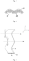
Fig. 4 is a structural diagram of a flat cable with the third type of cross section according to the present invention; -
Fig. 5 is a structural diagram showing a flat cable of the present invention bent toward an X-axis (not constituting a part of the present invention); -
Fig. 6 is a structural diagram showing a flat cable of the present invention bent toward a Y-axis (not constituting a part of the present invention); -
Fig. 7 is a structural diagram showing a flat cable of the present invention bent toward a Z-axis (not constituting a part of the present invention); -
Fig. 8 is a side perspective view ofFig 7 (not constituting a part of the present invention); and -
Fig. 9 is a diagram showing a flat cable of the present invention successively bent toward a Y-axis and a Z-axis (not constituting a part of the present invention). - The reference designators in
Figs. 1-9 are described below:
1. vehicle body shell; 2. plug; 3. power supply; 4. flat cable; 41. solid aluminum conductive core; 42. flexible insulation layer; 5. chamfer; 6a. bent portion; 6b. bent portion; 6c. bent portion; 6e. bent portion; 6f. bent portion; α. bending angle; β. bending angle; γ. bending angle; 7. fastener; H. the distance between the flat cable and the vehicle body shell. - In order to further illustrate the technical solutions used in the present invention to realize the above-mentioned objectives and the functions thereof, the specific embodiments, structures, features, and functions of the present invention will be described in detail hereinafter with reference to the drawings and preferred embodiments. The details are as below.
-
Fig. 1-1 is the first diagram showing the wiring structure of the automotive vehicle according to the present invention. The automotive vehicle includes thevehicle body shell 1, thepower supply 3, the in-car plug orjunction device 2, and theflat cables 4 that partially or completely connect thepower supply 3 and the plug orjunction device 2. Theplug 2 and thepower supply 3 are respectively located at the front end and the back end of thevehicle body 1. Theflat cables 4 extend along thevehicle body shell 1, and the distance H between theflat cables 4 andvehicle body shell 1 is less than or equal to 300mm. - According to the present invention, existing round cables of the automotive vehicles are replaced partially or completely with the
flat cables 4. Owing to the flat cross section of theflat cable 4, the forces applied to the points on the flat cable are anisotropic, so the flat cables are easy to bend when being installed on thevehicle body shell 1, thereby greatly simplifying the installation process. - Moreover, the flat cable is installed at a location less than or equal to 300 mm from the
vehicle body shell 1, which is a location relatively close to the profile of the vehicle body shell. By doing so, the probability that the flat cable waggles during the bumping of a vehicle because the flat cable is located far from thevehicle body shell 1 can be effectively reduced, which can facilitate the improvement of the installation stability of the flat cables in vehicles. In the meantime, since the location is relatively closer to thevehicle body shell 1 compared to other locations, there is only a relatively small increase on the cable consumption in the wiring comparatively, so the material consumption in the cable installation can be reduced, the probability of abusing the cable wires can be reduced, a reasonable use of the cable wires can be ensured, and the installation cost can be reduced. Moreover, extending the flat cable along thevehicle body shell 1 is helpful in reducing the installation space of the flat cables in thevehicle body shell 1, so as to satisfy the requirement for simplifying the installation space by the people. - As an improvement of the present embodiment, the
flat cable 4 is fixed on thevehicle body shell 1 by several spaced-apart fasteners, and the interval between twoadjacent fasteners 7 is 10 - 200 cm. - The automotive vehicle of the present invention partially or completely uses the
flat cables 4. Compared with the existing automotive vehicle which completely uses the power supply cables having round cross section, in the vehicle disclosed by the present invention, the installation stability of the flat cables is better. Thus, when theflat cables 4 are fixed on thevehicle body shell 1 by several spaced-apartfasteners 7, the distance between two adjacent fasteners is merely 10 - 200 cm, i.e. at every 10 - 200 cm interval along the length direction of theflat cable 4, afastener 7 is provided. Compared with the use of power supply cables having round cross section of the same length, the use of the flat cable not only can firmly fix theflat cables 4 on thevehicle body shell 1 to further improve the installation stability of theflat cable 4 on thevehicle body shell 1, but also can reduce the use amount of thefasteners 7, thereby remarkably reducing the installation workload and reducing the installation cost and production cost. - As an improvement of the present embodiment, the distance between the
flat cable 4 and thevehicle body shell 1 is 2 - 100 mm. Within the value range, better effects can be obtained in the aspects of reducing the bending times of theflat cables 4, shortening the installation time, reducing the material consumption of theflat cables 4, and improving the installation stability of theflat cables 4 in thevehicle body shell 1. -
Figs. 1-2 and1-3 are the second and third diagrams showing the wiring structure of the automotive vehicle according to the present invention, and they are the top views ofFig. 1-1 . Specifically,Fig. 1-2 is a structural diagram of an automotive vehicle which completely uses the flat cables for connections, andFig. 1-3 is a structural diagram of an automotive vehicle which partially uses the flat cables for connections. - In order to reduce the cost of the automotive vehicle and the overall weight of the vehicle, and to facilitate the weight reduction of the vehicle, the
flat cable 4 includes the flat-shaped solid aluminumconductive core 41 and theflexible insulation layer 42 wrapping over the solid aluminumconductive core 41. - In terms of the
flat cable 4 of the present invention, the existing copper core is replaced with the solid aluminum conductive core 41 (wherein, in the present embodiment, the solid aluminumconductive core 41 may be an aluminum core or an aluminum alloy core). The density of aluminum is one third the density of copper. According to the electrical performances of aluminum and copper, i.e. the differences of electrical resistivity, on the basis that the conductivity performances are the same, the length to diameter ratio of aluminum is merely 1.28 times the length to diameter ratio of copper, while the weight of aluminum material is half the weight of copper material having the same current capacity. Thus, the weight of the lines can be greatly reduced, which is helpful in reducing the weight of the vehicle. By using the aluminumconductive core 41 having lower specific weight and lower cost instead of copper conductive core having higher specific weight and higher cost, the material cost and transportation cost can be reduced, thereby reducing the production cost of the automotive vehicle and satisfying the user's needs. - To recycle the
power supply 3 and achieve the purpose of energy saving and make it environment friendly, thepower supply 3 is a storage battery. - Besides the insulation performance, the
insulation layer 42 is a waterproof layer, a certain degree of elasticity, abrasion resistance, and rigidity, so as to protect theinsulation layer 42 in the subsequent processing and forming of the cable. - In order to protect the
flexible insulation layer 42, as shown inFig. 2 , the solid aluminumconductive core 41 has an ellipse-shaped cross section which can prevent the solid aluminumconductive core 41 from piercing through the flexible insulation layer 42 (not constituting a part of the present invention). - In order to better fit with the profile of the
vehicle body shell 1 in the wiring, the solid aluminumconductive core 41 may also be polygon-shaped, and the polygon shape may be a quadrilateral , a pentagon, a hexagon, or an octagon etc (not constituting a part of the present invention). - When the polygon shape is a quadrilateral shape, as a further improvement of the
flat cable 4 as shown inFig. 3 , the quadrilateral shape is a rectangle. In order to ensure that people can bend theflat cable 4 according to the profile of thevehicle body shell 1 for wiring in the basis of satisfying the conductivity requirement of theflat cable 4, the rectangle has a height range of 2mm-4.5mm and a width range of 15mm-33mm. Further, in order to facilitate the processing and formation of theflat cable 4, preferably, the rectangle has a height range of 3.4mm-4.0mm and a width range of 29.7 mm-30.3 mm (not constituting a part of the present invention). - As shown in the
Fig. 4 , the solid aluminum conductive core has a ripple-shaped cross section, so that theflat cable 4 matches better with the profile of thevehicle body shell 1, and the installation space can be further reduced. Moreover, the flat cable composed of the solid aluminum conductive cores with the above-mentioned cross sectional shape has a wavy structure. - When the solid aluminum
conductive core 41 has a polygonal cross section, taking the embodiment shown inFig. 3 as an example, the corners of the polygon need to be processed to have fillets, so as to protect theflexible insulation layer 42. Namely, each corner of the polygon has achamfer 5. By doing so, besides preventing the sharp edge from piercing through theflexible insulation layer 42, an electric discharge of burr due to an overcurrent and a breakdown can be avoided, thereby effectively protecting theflat cables 4 and prolonging the service life of the flat cables 4 (not constituting a part of the present invention). - Since the solid aluminum
conductive cores 41 are more flexible than copper conductive cores, have a good bending performance, and allow a smaller bending radius, a bending forming is added to the design of theflat cable 4 in the present invention. The bent portions depend on the concave and convex pattern of the profile of the vehicle body shell, and the standard is to fit well with the vehicle body shell. The bending shape is formed in the below ways: with one end fixed, the other end is bent 0-180° along an arbitrary direction of an X-axis, a Y-axis, or a Z-axis in a three-dimensional coordinate system. The bent portion may have a certain radian, and/or be successively bent, or be wrapped over parts of automotive vehicle. In terms of the bending mode, it is not limited to be perpendicular to the edge of theflat cable 4, an angle with the edge of the cable is also acceptable. The forming method of the cable may be extrusion, wrapping over a fixed module, or twisting etc. A small scale of recovery is allowed without influencing the installation effect after the bending portion is shaped. - It should be noted that, the vehicle body shell in the present invention includes components such as chassis, frame shell, doors, and so on.
- The bending performance of the
flat cable 4 in the present invention are specifically described in three aspects below. - As shown in
Fig. 5 , when the flat cable is bent toward the X-axis, the upper end of theflat cable 4 is fixed, the bent portion is referred to as 6a and the bending angle is indicated as α in the drawing, and the bending direction is the positive X-axis in the drawing. The flat cable can be successively bent if necessary. Namely, the portion including the bendingportion 6a is fixed, the bending is performed about another bendingportion 6b. Besides the positive X-axis, the bending direction may be the negative X-axis, and the bending angle is indicated as β in the drawing. After all, a wavyflat cable 4 can be formed on the X-Z plane shown in the drawing. - As shown in
Fig. 6 , when theflat cable 4 is twisted toward the X-axis in the drawing, the twisted portion is indicated as 6c in the drawing. With one end of theflat cable 4 fixed, the other end is twisted 180° about the X-axis. In this case, the upper and lower surfaces of the left and right sides are opposite. The flat surface of theflat cable 4 is located on the X-Z plane shown in the drawing. Here, the twisting angle not limited to 180°. - In the case where the
flat cable 4 is bent toward the Z-axis, as shown inFig. 7 , the bending portion is indicated as 6d in the drawing. With one end of theflat cable 4 fixed, another end is bent toward the Z-axis with a bending angle which is indicated as γ to obtain the desired shape. If the cable is successively bent, the part including the bent portion should be fixed, and the other side is further bent to obtain the shape shown inFig. 5 .Fig.8 shows a side perspective view of theflat cable 4 which is bent toward the Z-axis with a certain angle. - It is not limited to bend the
flat cable 4 successively in the same plane, the cable may also be bent successively toward different planes, so as to obtain more stereoscopic structure of theflat cable 4 to better fit with the vehicle body. As shown inFig. 9 , for oneflat cable 4, thebent portion 6e is first twisted along the X-axis at a certain angle, and then thebent portion 6f is successively bent along the Z-axis at a certain angle to obtain the flat cable with a new shape. - The above-mentioned embodiments are merely preferred embodiments of the present invention, and it is improper to use these embodiments to limit the scope of the present invention. Any immaterial modifications and substitutions made by those skilled in the art based on the present invention should be considered as falling within the scope of the present invention.
Claims (3)
- An automotive vehicle comprising a vehicle body shell (1), a power supply (3), and an in-car plug (2) or junction device, wherein the power supply (3) is connected to the in-car plug (2) or junction device partially or completely by flat cables (4), and the flat cables (4) extend along the vehicle body shell (1), wherein each of the flat cables (4) comprises a solid conductive core with a flat cross section and a flexible insulation layer (42) wrapping over the solid conductive core, and a distance (H) between the flat cables (4) and the vehicle body shell (1) is less than or equal to 300mm; characterized in that the solid conductive core is made of aluminium, and the solid aluminum conductive core (41) has a ripple-shaped cross section.
- The automotive vehicle according to claim 1, characterized in that the flat cables (4) are fixed on the vehicle body shell (1) by a plurality of spaced-apart fasteners (7), and an interval distance between two adjacent fasteners (7) is 10-200cm.
- A flat cable (4) for an automotive vehicle having a vehicle body shell (1), a power supply (3), and an in-car plug (2) or junction device, wherein the flat cable (4) connects the power supply (3) to the in-car plug (2) or junction device partially or completely, and the flat cable (4) extends along the vehicle body shell (1), wherein each of the flat cables (4) comprises a solid conductive core with a flat cross section and a flexible insulation layer (42) wrapping over the solid conductive core, and a distance (H) between the flat cables (4) and the vehicle body shell (1) is less than or equal to 300mm; characterized in that the solid conductive core is made of aluminium, and the solid aluminum conductive core (41) has a ripple-shaped cross section.
Applications Claiming Priority (2)
| Application Number | Priority Date | Filing Date | Title |
|---|---|---|---|
| CN201621267142.5U CN206217803U (en) | 2016-11-22 | 2016-11-22 | A kind of motor vehicles |
| PCT/CN2017/107578 WO2018095178A1 (en) | 2016-11-22 | 2017-10-25 | Automotive vehicle |
Publications (4)
| Publication Number | Publication Date |
|---|---|
| EP3530525A1 EP3530525A1 (en) | 2019-08-28 |
| EP3530525A4 EP3530525A4 (en) | 2019-11-13 |
| EP3530525C0 EP3530525C0 (en) | 2024-09-25 |
| EP3530525B1 true EP3530525B1 (en) | 2024-09-25 |
Family
ID=58791535
Family Applications (1)
| Application Number | Title | Priority Date | Filing Date |
|---|---|---|---|
| EP17873219.4A Active EP3530525B1 (en) | 2016-11-22 | 2017-10-25 | Automotive vehicle |
Country Status (9)
| Country | Link |
|---|---|
| US (1) | US20190263338A1 (en) |
| EP (1) | EP3530525B1 (en) |
| JP (1) | JP7270543B2 (en) |
| CN (1) | CN206217803U (en) |
| ES (1) | ES2987947T3 (en) |
| HU (1) | HUE069189T2 (en) |
| MX (1) | MX2019005595A (en) |
| PL (1) | PL3530525T3 (en) |
| WO (1) | WO2018095178A1 (en) |
Families Citing this family (5)
| Publication number | Priority date | Publication date | Assignee | Title |
|---|---|---|---|---|
| CN206217803U (en) * | 2016-11-22 | 2017-06-06 | 吉林省中赢高科技有限公司 | A kind of motor vehicles |
| JP6947123B2 (en) * | 2018-05-25 | 2021-10-13 | 株式会社オートネットワーク技術研究所 | Wiring member |
| JP2020010577A (en) * | 2018-07-12 | 2020-01-16 | 矢崎総業株式会社 | Routing structure of two-core parallel shielded wires |
| JP7371550B2 (en) * | 2020-03-23 | 2023-10-31 | 株式会社オートネットワーク技術研究所 | wire harness |
| DE102022202240A1 (en) * | 2022-03-04 | 2023-09-07 | Leoni Bordnetz-Systeme Gmbh | Device for electrical power distribution in a motor vehicle and conductor rail arrangement for a motor vehicle |
Citations (3)
| Publication number | Priority date | Publication date | Assignee | Title |
|---|---|---|---|---|
| US20070066101A1 (en) * | 2005-07-20 | 2007-03-22 | Yazaki Corporation | Flat cable clamp |
| DE102014011180A1 (en) * | 2014-07-31 | 2016-02-04 | Auto-Kabel Management Gmbh | Electrical flat conductor for motor vehicles |
| DE102015220115A1 (en) * | 2015-10-15 | 2017-04-20 | Lisa Dräxlmaier GmbH | ELECTRICAL ENERGY SUPPLY SYSTEM AND MANUFACTURING METHOD FOR SUCH A |
Family Cites Families (15)
| Publication number | Priority date | Publication date | Assignee | Title |
|---|---|---|---|---|
| US4845315A (en) * | 1984-05-02 | 1989-07-04 | Mosaic Systems | Cable system |
| JP3011521B2 (en) * | 1991-03-28 | 2000-02-21 | 矢崎総業株式会社 | Electric wiring structure for vehicles |
| FI962544A7 (en) * | 1996-06-19 | 1997-12-20 | Oy Iws Int Inc | Flat cable and method for manufacturing the same |
| EP1701362A3 (en) * | 2005-03-10 | 2007-02-14 | Gebauer & Griller Kabelwerke Gesellschaft m.b.H. | Power cable |
| JP2007076408A (en) * | 2005-09-12 | 2007-03-29 | Auto Network Gijutsu Kenkyusho:Kk | Power feeding device using flat cable |
| CN101083160A (en) * | 2006-06-01 | 2007-12-05 | 泛达公司 | Conductor with non-circular cross-section |
| US7572980B2 (en) * | 2007-01-26 | 2009-08-11 | Ford Global Technologies, Llc | Copper conductor with anodized aluminum dielectric layer |
| DE102007027858B4 (en) * | 2007-06-13 | 2012-11-15 | Auto-Kabel Management Gmbh | Motor vehicle power cable |
| DE102009032987A1 (en) * | 2009-07-14 | 2011-01-27 | Eifelwerk Heinrich Stein Gmbh & Co Kg | Electric line for use as battery line for motor vehicle, has elongated conductor provided with section with cross-section surface formed in form of circular area, where conductor is formed as single piece |
| JP2011134667A (en) * | 2009-12-25 | 2011-07-07 | Autonetworks Technologies Ltd | Wire harness |
| JP2013030327A (en) * | 2011-07-27 | 2013-02-07 | Yazaki Corp | Flat cable, and manufacturing method therefor |
| JP2013093144A (en) * | 2011-10-24 | 2013-05-16 | Toyota Motor Corp | Wire harness |
| DE202015103854U1 (en) * | 2015-07-22 | 2015-08-10 | Bayerische Motoren Werke Aktiengesellschaft | Track for use in the electrical system or as a battery line of vehicles |
| DE102015118921A1 (en) * | 2015-11-04 | 2017-05-04 | Auto-Kabel Management Gmbh | Multiple voltage onboard power supply system as well as voltage levels - comprehensive multilayer cable |
| CN206217803U (en) * | 2016-11-22 | 2017-06-06 | 吉林省中赢高科技有限公司 | A kind of motor vehicles |
-
2016
- 2016-11-22 CN CN201621267142.5U patent/CN206217803U/en active Active
-
2017
- 2017-10-25 MX MX2019005595A patent/MX2019005595A/en unknown
- 2017-10-25 PL PL17873219.4T patent/PL3530525T3/en unknown
- 2017-10-25 HU HUE17873219A patent/HUE069189T2/en unknown
- 2017-10-25 US US16/462,556 patent/US20190263338A1/en not_active Abandoned
- 2017-10-25 ES ES17873219T patent/ES2987947T3/en active Active
- 2017-10-25 EP EP17873219.4A patent/EP3530525B1/en active Active
- 2017-10-25 JP JP2019524238A patent/JP7270543B2/en active Active
- 2017-10-25 WO PCT/CN2017/107578 patent/WO2018095178A1/en not_active Ceased
Patent Citations (3)
| Publication number | Priority date | Publication date | Assignee | Title |
|---|---|---|---|---|
| US20070066101A1 (en) * | 2005-07-20 | 2007-03-22 | Yazaki Corporation | Flat cable clamp |
| DE102014011180A1 (en) * | 2014-07-31 | 2016-02-04 | Auto-Kabel Management Gmbh | Electrical flat conductor for motor vehicles |
| DE102015220115A1 (en) * | 2015-10-15 | 2017-04-20 | Lisa Dräxlmaier GmbH | ELECTRICAL ENERGY SUPPLY SYSTEM AND MANUFACTURING METHOD FOR SUCH A |
Also Published As
| Publication number | Publication date |
|---|---|
| PL3530525T3 (en) | 2025-01-07 |
| US20190263338A1 (en) | 2019-08-29 |
| EP3530525A1 (en) | 2019-08-28 |
| JP7270543B2 (en) | 2023-05-10 |
| EP3530525A4 (en) | 2019-11-13 |
| JP2019535574A (en) | 2019-12-12 |
| ES2987947T3 (en) | 2024-11-18 |
| WO2018095178A1 (en) | 2018-05-31 |
| EP3530525C0 (en) | 2024-09-25 |
| CN206217803U (en) | 2017-06-06 |
| HUE069189T2 (en) | 2025-02-28 |
| MX2019005595A (en) | 2019-09-06 |
Similar Documents
| Publication | Publication Date | Title |
|---|---|---|
| EP3530525B1 (en) | Automotive vehicle | |
| US9496071B2 (en) | Shield wire | |
| EP2894738B1 (en) | Wire harness | |
| US9112287B2 (en) | Swaging connection structure | |
| JP5927692B2 (en) | Wire harness | |
| JP2012243550A (en) | High voltage electric wire and manufacturing method of high voltage electric wire | |
| JP2011254614A (en) | Wire harness | |
| JP2011165354A (en) | Wire harness | |
| JP2013115072A (en) | Shield structure and wire harness | |
| US20140325837A1 (en) | Method of manufacturing ground connection structure | |
| US11018480B2 (en) | Bus bar electric wire with a bent portion of uniform elongation | |
| JP5957779B2 (en) | Wire harness | |
| JP2013158226A (en) | Protector and wire harness | |
| US20160137146A1 (en) | Shielded wire and wire harness | |
| US10913406B2 (en) | Wire protection pipe and wire harness | |
| EP2874154B1 (en) | Wire harness | |
| JP5781289B2 (en) | Wire harness wiring structure | |
| JP6461358B2 (en) | Charging connector and hand cart equipped with the same | |
| CN214673031U (en) | Bow interfacing apparatus charges | |
| CN203205482U (en) | Binding post terminal of automobile storage battery | |
| JP2020053377A (en) | Flat wire | |
| CN214798746U (en) | Wire protecting sleeve | |
| CN222601536U (en) | A kind of USB data cable that can prevent breaking | |
| CN212637370U (en) | Automobile storage battery junction box | |
| CN201629535U (en) | Safety box for automobile cabin |
Legal Events
| Date | Code | Title | Description |
|---|---|---|---|
| STAA | Information on the status of an ep patent application or granted ep patent |
Free format text: STATUS: THE INTERNATIONAL PUBLICATION HAS BEEN MADE |
|
| PUAI | Public reference made under article 153(3) epc to a published international application that has entered the european phase |
Free format text: ORIGINAL CODE: 0009012 |
|
| STAA | Information on the status of an ep patent application or granted ep patent |
Free format text: STATUS: REQUEST FOR EXAMINATION WAS MADE |
|
| 17P | Request for examination filed |
Effective date: 20190521 |
|
| AK | Designated contracting states |
Kind code of ref document: A1 Designated state(s): AL AT BE BG CH CY CZ DE DK EE ES FI FR GB GR HR HU IE IS IT LI LT LU LV MC MK MT NL NO PL PT RO RS SE SI SK SM TR |
|
| AX | Request for extension of the european patent |
Extension state: BA ME |
|
| A4 | Supplementary search report drawn up and despatched |
Effective date: 20191014 |
|
| RIC1 | Information provided on ipc code assigned before grant |
Ipc: H01B 7/04 20060101ALI20191008BHEP Ipc: H01B 7/08 20060101ALI20191008BHEP Ipc: H01B 7/00 20060101ALI20191008BHEP Ipc: B60R 16/02 20060101AFI20191008BHEP |
|
| DAV | Request for validation of the european patent (deleted) | ||
| DAX | Request for extension of the european patent (deleted) | ||
| STAA | Information on the status of an ep patent application or granted ep patent |
Free format text: STATUS: EXAMINATION IS IN PROGRESS |
|
| 17Q | First examination report despatched |
Effective date: 20220223 |
|
| GRAP | Despatch of communication of intention to grant a patent |
Free format text: ORIGINAL CODE: EPIDOSNIGR1 |
|
| STAA | Information on the status of an ep patent application or granted ep patent |
Free format text: STATUS: GRANT OF PATENT IS INTENDED |
|
| INTG | Intention to grant announced |
Effective date: 20240502 |
|
| GRAS | Grant fee paid |
Free format text: ORIGINAL CODE: EPIDOSNIGR3 |
|
| GRAA | (expected) grant |
Free format text: ORIGINAL CODE: 0009210 |
|
| STAA | Information on the status of an ep patent application or granted ep patent |
Free format text: STATUS: THE PATENT HAS BEEN GRANTED |
|
| AK | Designated contracting states |
Kind code of ref document: B1 Designated state(s): AL AT BE BG CH CY CZ DE DK EE ES FI FR GB GR HR HU IE IS IT LI LT LU LV MC MK MT NL NO PL PT RO RS SE SI SK SM TR |
|
| REG | Reference to a national code |
Ref country code: GB Ref legal event code: FG4D |
|
| REG | Reference to a national code |
Ref country code: CH Ref legal event code: EP |
|
| REG | Reference to a national code |
Ref country code: DE Ref legal event code: R096 Ref document number: 602017085132 Country of ref document: DE |
|
| REG | Reference to a national code |
Ref country code: IE Ref legal event code: FG4D |
|
| U01 | Request for unitary effect filed |
Effective date: 20241001 |
|
| REG | Reference to a national code |
Ref country code: ES Ref legal event code: FG2A Ref document number: 2987947 Country of ref document: ES Kind code of ref document: T3 Effective date: 20241118 |
|
| U07 | Unitary effect registered |
Designated state(s): AT BE BG DE DK EE FI FR IT LT LU LV MT NL PT RO SE SI Effective date: 20241024 |
|
| REG | Reference to a national code |
Ref country code: SK Ref legal event code: T3 Ref document number: E 45126 Country of ref document: SK |
|
| U20 | Renewal fee for the european patent with unitary effect paid |
Year of fee payment: 8 Effective date: 20241025 |
|
| PG25 | Lapsed in a contracting state [announced via postgrant information from national office to epo] |
Ref country code: GR Free format text: LAPSE BECAUSE OF FAILURE TO SUBMIT A TRANSLATION OF THE DESCRIPTION OR TO PAY THE FEE WITHIN THE PRESCRIBED TIME-LIMIT Effective date: 20241226 |
|
| PG25 | Lapsed in a contracting state [announced via postgrant information from national office to epo] |
Ref country code: RS Free format text: LAPSE BECAUSE OF FAILURE TO SUBMIT A TRANSLATION OF THE DESCRIPTION OR TO PAY THE FEE WITHIN THE PRESCRIBED TIME-LIMIT Effective date: 20241225 |
|
| PG25 | Lapsed in a contracting state [announced via postgrant information from national office to epo] |
Ref country code: RS Free format text: LAPSE BECAUSE OF FAILURE TO SUBMIT A TRANSLATION OF THE DESCRIPTION OR TO PAY THE FEE WITHIN THE PRESCRIBED TIME-LIMIT Effective date: 20241225 Ref country code: GR Free format text: LAPSE BECAUSE OF FAILURE TO SUBMIT A TRANSLATION OF THE DESCRIPTION OR TO PAY THE FEE WITHIN THE PRESCRIBED TIME-LIMIT Effective date: 20241226 |
|
| REG | Reference to a national code |
Ref country code: HU Ref legal event code: AG4A Ref document number: E069189 Country of ref document: HU |
|
| PG25 | Lapsed in a contracting state [announced via postgrant information from national office to epo] |
Ref country code: IS Free format text: LAPSE BECAUSE OF FAILURE TO SUBMIT A TRANSLATION OF THE DESCRIPTION OR TO PAY THE FEE WITHIN THE PRESCRIBED TIME-LIMIT Effective date: 20250125 |
|
| PG25 | Lapsed in a contracting state [announced via postgrant information from national office to epo] |
Ref country code: SM Free format text: LAPSE BECAUSE OF FAILURE TO SUBMIT A TRANSLATION OF THE DESCRIPTION OR TO PAY THE FEE WITHIN THE PRESCRIBED TIME-LIMIT Effective date: 20240925 |
|
| PG25 | Lapsed in a contracting state [announced via postgrant information from national office to epo] |
Ref country code: MC Free format text: LAPSE BECAUSE OF FAILURE TO SUBMIT A TRANSLATION OF THE DESCRIPTION OR TO PAY THE FEE WITHIN THE PRESCRIBED TIME-LIMIT Effective date: 20240925 |
|
| PLBE | No opposition filed within time limit |
Free format text: ORIGINAL CODE: 0009261 |
|
| STAA | Information on the status of an ep patent application or granted ep patent |
Free format text: STATUS: NO OPPOSITION FILED WITHIN TIME LIMIT |
|
| 26N | No opposition filed |
Effective date: 20250626 |
|
| U20 | Renewal fee for the european patent with unitary effect paid |
Year of fee payment: 9 Effective date: 20250904 |
|
| PG25 | Lapsed in a contracting state [announced via postgrant information from national office to epo] |
Ref country code: NO Free format text: LAPSE BECAUSE OF NON-PAYMENT OF DUE FEES Effective date: 20241225 |
|
| PGFP | Annual fee paid to national office [announced via postgrant information from national office to epo] |
Ref country code: GB Payment date: 20250904 Year of fee payment: 9 |
|
| PG25 | Lapsed in a contracting state [announced via postgrant information from national office to epo] |
Ref country code: IE Free format text: LAPSE BECAUSE OF NON-PAYMENT OF DUE FEES Effective date: 20241025 |
|
| PGFP | Annual fee paid to national office [announced via postgrant information from national office to epo] |
Ref country code: SK Payment date: 20250925 Year of fee payment: 9 |
|
| REG | Reference to a national code |
Ref country code: CH Ref legal event code: U11 Free format text: ST27 STATUS EVENT CODE: U-0-0-U10-U11 (AS PROVIDED BY THE NATIONAL OFFICE) Effective date: 20251101 |
|
| PGFP | Annual fee paid to national office [announced via postgrant information from national office to epo] |
Ref country code: HU Payment date: 20250923 Year of fee payment: 9 |
|
| PG25 | Lapsed in a contracting state [announced via postgrant information from national office to epo] |
Ref country code: HR Free format text: LAPSE BECAUSE OF FAILURE TO SUBMIT A TRANSLATION OF THE DESCRIPTION OR TO PAY THE FEE WITHIN THE PRESCRIBED TIME-LIMIT Effective date: 20240925 |
|
| PGFP | Annual fee paid to national office [announced via postgrant information from national office to epo] |
Ref country code: CH Payment date: 20251101 Year of fee payment: 9 |
|
| PGFP | Annual fee paid to national office [announced via postgrant information from national office to epo] |
Ref country code: CZ Payment date: 20251020 Year of fee payment: 9 |
|
| PGFP | Annual fee paid to national office [announced via postgrant information from national office to epo] |
Ref country code: PL Payment date: 20251017 Year of fee payment: 9 |
|
| PG25 | Lapsed in a contracting state [announced via postgrant information from national office to epo] |
Ref country code: CY Free format text: LAPSE BECAUSE OF FAILURE TO SUBMIT A TRANSLATION OF THE DESCRIPTION OR TO PAY THE FEE WITHIN THE PRESCRIBED TIME-LIMIT; INVALID AB INITIO Effective date: 20171025 |
|
| PGFP | Annual fee paid to national office [announced via postgrant information from national office to epo] |
Ref country code: ES Payment date: 20251121 Year of fee payment: 9 |
|
| U1N | Appointed representative for the unitary patent procedure changed after the registration of the unitary effect |
Representative=s name: MARKS & CLERK LLP; GB |