EP3530522A2 - Sensoreinrichtung für ein kraftfahrzeug, verfahren sowie kraftfahrzeug - Google Patents
Sensoreinrichtung für ein kraftfahrzeug, verfahren sowie kraftfahrzeug Download PDFInfo
- Publication number
- EP3530522A2 EP3530522A2 EP19157195.9A EP19157195A EP3530522A2 EP 3530522 A2 EP3530522 A2 EP 3530522A2 EP 19157195 A EP19157195 A EP 19157195A EP 3530522 A2 EP3530522 A2 EP 3530522A2
- Authority
- EP
- European Patent Office
- Prior art keywords
- sensor
- housing
- sensor device
- motor vehicle
- disk
- Prior art date
- Legal status (The legal status is an assumption and is not a legal conclusion. Google has not performed a legal analysis and makes no representation as to the accuracy of the status listed.)
- Granted
Links
Images
Classifications
-
- G—PHYSICS
- G01—MEASURING; TESTING
- G01S—RADIO DIRECTION-FINDING; RADIO NAVIGATION; DETERMINING DISTANCE OR VELOCITY BY USE OF RADIO WAVES; LOCATING OR PRESENCE-DETECTING BY USE OF THE REFLECTION OR RERADIATION OF RADIO WAVES; ANALOGOUS ARRANGEMENTS USING OTHER WAVES
- G01S7/00—Details of systems according to groups G01S13/00, G01S15/00, G01S17/00
- G01S7/48—Details of systems according to groups G01S13/00, G01S15/00, G01S17/00 of systems according to group G01S17/00
- G01S7/481—Constructional features, e.g. arrangements of optical elements
- G01S7/4811—Constructional features, e.g. arrangements of optical elements common to transmitter and receiver
- G01S7/4813—Housing arrangements
-
- G—PHYSICS
- G01—MEASURING; TESTING
- G01S—RADIO DIRECTION-FINDING; RADIO NAVIGATION; DETERMINING DISTANCE OR VELOCITY BY USE OF RADIO WAVES; LOCATING OR PRESENCE-DETECTING BY USE OF THE REFLECTION OR RERADIATION OF RADIO WAVES; ANALOGOUS ARRANGEMENTS USING OTHER WAVES
- G01S17/00—Systems using the reflection or reradiation of electromagnetic waves other than radio waves, e.g. lidar systems
- G01S17/88—Lidar systems specially adapted for specific applications
- G01S17/93—Lidar systems specially adapted for specific applications for anti-collision purposes
- G01S17/931—Lidar systems specially adapted for specific applications for anti-collision purposes of land vehicles
Definitions
- the invention relates to a sensor device for a motor vehicle, a method for adjusting a measured value determined by means of a sensor device and a motor vehicle having a sensor device.
- Sensor devices for motor vehicles are already well known. Modern, high-resolution environmental sensors of sensor devices form a basis for complex driver assistance functions and highly automated driving. Thus, motor vehicles are already equipped with a plurality of sensor devices on the outside and inside to detect measurement data, depending on which a control of the respective motor vehicle can be supported or executed.
- Object of the present invention is to provide a particularly robust sensor device for a motor vehicle, a method for adjusting a measured value determined by means of the sensor device as well as a motor vehicle with such a robust sensor device.
- a first aspect of the invention relates to a sensor device for a motor vehicle, having a housing in which a sensor element is accommodated.
- the sensor element is accommodated in particular in a volume which is at least substantially enclosed by the housing and thus enclosed by the housing at least essentially, in particular on the circumference.
- the sensor device further comprises a disc element covering an opening of the housing, by means of which measured values of an environment of the sensor device can be determined by means of the sensor element.
- the measured values can be determined from the surroundings of the sensor device by means of the sensor element through the disk element.
- the opening of the housing and / or the disc element are circular.
- the disk element and the opening can be arranged concentrically with each other by means of the compensating element.
- the disk element can in this case be arranged along a central axis of the opening overlapping with the opening of the housing. In this way, a restriction of a field of view of the sensor element can be avoided.
- the disk element is arranged on the housing for enabling a relative movement to the housing under the mediation of a compensating element.
- the compensation element is arranged both on the housing and on the disk element and that the compensation element allows the relative movement of the disk element relative to the housing.
- the compensation element is particularly flexible and deformable to compensate for the relative movement between the housing and the disc element. When the disk element is moved, the compensating element dampens the movement of the disk element with respect to the housing.
- the sensor element accommodated by the housing is therefore particularly advantageously protected against damage, since the compensation element prevents deformation of the housing and thus damage to the sensor element. Furthermore, enclosing the sensor element by the housing prevents damage to the Sensor element due to a possible collision with the disc element before. Consequently, the sensor device is designed to be particularly robust.
- the sensor element is an optical sensor.
- the field of view of the optical sensor passes through the disk element into the surroundings of the motor vehicle.
- This may be, for example, a laser sensor in the optical sensor.
- the laser sensor can be particularly well protected due to its arrangement within the housing and due to the relative mobility of the disc member to the housing, as by means of the compensating element, a movement of the disc member is buffered with respect to the housing.
- the environment of the motor vehicle can be detected via the field of view by means of the opitschen sensor.
- the disc element has a larger diameter than the opening of the housing. In this way it can be ensured that the viewing area of the sensor element is not limited by the disk element with respect to its circumference, but is predetermined by the opening of the housing or by the sensor element itself. In this way, the greatest possible field of view of the sensor element can be made possible.
- the compensating element comprises a spring device.
- the compensation element has at least one spring, in particular a spiral spring, by means of which the relative movement between the disc element and the housing can be compensated.
- the spiral spring may have a central axis which extends through an opening center of the opening of the housing and / or through a disk center of the disk element.
- the spiral spring extends circumferentially the opening of the housing or circumferentially of the disk element.
- the compensating element and the disc element seal the housing airtight.
- the sensor element accommodated in the housing is completely enclosed by the housing, the compensation element and the disk element.
- the sensor element is arranged in an at least substantially closed volume, so that contamination of the sensor element can be at least substantially avoided. As a result, damage to the sensor element due to contamination can be prevented.
- the compensation element is adapted at its the disk element facing the first side to a pulley diameter of the disk element and tapers in its balancing diameter to the opening of the housing.
- the compensation element rests on its first side on the outer peripheral side of the disk element.
- the compensation element may have a first compensation diameter, which corresponds at least substantially to the disk diameter of the disk element. In this way it can be ensured that the field of view of the sensor element is released from the compensation element and thus is not limited by the compensation element.
- the compensation element is adapted to the opening of the housing.
- the compensating element tapers from the disk element towards the opening of the housing.
- the compensation element may have a second compensation diameter, which corresponds at least substantially to an opening diameter of the opening of the housing. This serves to release the field of view of the sensor element by means of the compensating element, so that the field of view of the sensor element is not restricted by the compensating element.
- the compensation element is conical.
- the term "conical” is to be understood in particular as meaning that the respective compensating diameter of the compensating element increases continuously and optionally evenly from the second compensating diameter of the second side to the first compensating diameter of the first side. This can ensure that the field of view of the sensor element is released by the compensation element and is not limited by the compensation element.
- a further aspect of the invention relates to a method for adjusting a measured value determined by means of the sensor device according to the invention, in which an alignment of the disk element relative to the sensor element is detected and the measured value determined by means of the sensor element is adjusted as a function of the orientation.
- the measured value can be adjusted by means of a computing device as a function of the orientation.
- an alignment detection device is provided, by means of which the orientation of the disk element relative to the sensor element can be detected and provided for the computing device.
- a respective orientation of the disk element may influence an optical signal which is detected from the environment via the disk element by means of the sensor element as a measured value. Based on the orientation of the disk element, the respective refraction of the optical signal detected by means of the sensor element can be determined and the measured value can be adjusted as a function of this.
- Another aspect of the invention relates to a motor vehicle with a sensor device according to the invention. Since the sensor device according to the invention is particularly robust, detection of measured values by means of the sensor device on the motor vehicle can be ensured. As a result, for example, the motor vehicle can be controlled particularly reliably as a function of measured data determined by means of the sensor device.
- the housing of the sensor device is at least indirectly attached to a support element of a bumper of the motor vehicle and the disc element is disposed in an opening of a bumper fascia of the motor vehicle.
- the housing is rigidly fastened, for example, to the carrier element of the bumper, whereas the disc element is movable relative to the bumper fascia.
- the sensor element is advantageously fastened particularly securely to the carrier element of the bumper while the disk element is relatively movable relative to the housing of the sensor device. The sensor element is thus protected from damage as a result of a relative movement of the disk element to the housing, in particular due to a collision of an element with the disk element.
- the invention also includes further developments of the method according to the invention and of the motor vehicle according to the invention which have features which have already been described in connection with the developments of the sensor device according to the invention. For this reason, the corresponding developments of the method according to the invention and the motor vehicle according to the invention are not described again here.
- the invention also includes combinations of the described embodiments.
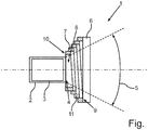
- Fig. Shows a schematic sectional view of a sensor device for a motor vehicle with a housed in a housing Sensor element and with a compensating element relatively movably held on the housing disc element which releases a field of view of the sensor element.
- the described components of the embodiments each represent individual features of the invention, which are to be considered independently of one another, which each further develop the invention independently of one another and thus also individually or in a different combination than the one shown as part of the invention. Furthermore, the described embodiments can also be supplemented by further features of the invention already described.
- the single FIGURE shows a schematic sectional view of a sensor device 1 for a motor vehicle.
- the sensor device 1 By means of the sensor device 1, measured values of an environment of the motor vehicle can be determined and the motor vehicle can be operated as a function of the measured values determined by means of the sensor device 1.
- the sensor device 1 can be a parking sensor, by means of which a distance between the motor vehicle having the sensor device 1 and a further object is determined in order to support the motor vehicle during a parking operation.
- the sensor device 1 comprises a sensor element 3 accommodated by a housing 2.
- the housing 2 has an opening 4 through which a viewing region 5 of the sensor element 3 extends.
- the sensor element 3 is an optical sensor which detects the surroundings of the motor vehicle in the field of view 5.
- the viewing area 5 is in particular conical.
- the sensor device 1 further comprises a disc element 6, which in the present case is of circular design and is shown in its FIG Starting position is arranged concentrically to the circular opening 4 of the housing 2.
- contamination of the sensor element 3 can be prevented.
- the disk element 6 is arranged to enable a relative movement to the housing 2 by means of the compensation element 7 on the housing 2.
- the compensation element 7 is arranged on its first side 9 adjacent to the disk element 6 and arranged on its second side 10 adjacent to the housing 2.
- the compensating element 7 is supported at one end on the disc element 6 and the other end on the housing 2.
- the first side 9 of the compensating element 7 has the same outer diameter as the disc element 6.
- the compensating element 7 is supported on the housing 2 in the region of the opening 4.
- the compensation element 7 in the present case has a telescopic spring element 11.
- This telescopic spring element 11 has at least substantially a conical shape, which tapers from the disk element 6 to the opening 4 of the housing 2.
- the sensor device 1 is in the present case at least substantially rotationally symmetrical.
- the housing 2 of the sensor device 1 can be attached at least indirectly to a carrier element of a bumper of the motor vehicle and the disc element 6 can be arranged in an opening of a bumper cover of the motor vehicle.
- the disk element 6 of the sensor device 1 faces the surroundings of the motor vehicle, whereas the housing 2 of the sensor device 1 faces away from the surroundings of the motor vehicle.
- the disc member 6 can be flush with the bumper fascia of the motor vehicle to produce a smooth outer surface of the motor vehicle.
- a measured value determined by means of the sensor device 1 can be adjusted relative to the sensor element 3 when the sensor device 1 is operated as a function of an orientation of the disk element 6.
- an alignment detection device (not shown in the single FIGURE) can be provided, by means of which the orientation of the disk element 6 relative to the sensor element 3 is detected.
- the orientation of the disk element 6 detected by means of the orientation detection device can be evaluated relative to the sensor element 3 and the measured value detected by the sensor element 3 can be adapted.
- the measured value can be adjusted as a function of deviations of the orientation from the initial position, which can result from slight tilting of the disk element 6 after a parking bump. After the adjustment, the measured value can be further processed, in particular for controlling the motor vehicle.
- the described sensor device 1 is based on the finding that modern, high-resolution environmental sensors form a basis for complex driver assistance functions and highly automated driving.
- Today's environment sensors are installed as a rigid unit in a vehicle, often in a front area.
- a windshield element of an optical laser scanner sensor corresponding to the disk element 6 is usually glued to a laser scanner housing and forms an essential part of the laser scanner housing.
- An installation of environment sensors behind the protective window of the vehicle is possible and advantageous for individual environment sensors such as a camera, but not all necessary environmental sensors can be accommodated there.
- a respective sensor range of the environmental sensors is severely limited by shading the vehicle front, in particular, a ground on which the vehicle is only seen at a distance of about 10 m.
- the environmental sensors behind the windshield can take up space in an upper disk area and thus restrict a driver's driver's visibility area. Other requirements such as a maximum temperature and variants due to a variety of different windshields complicate the placement of environmental sensors in this area in addition.
- a stable installation of the environment sensors in the vehicle front outside a service area is possible in principle, but typically not compatible with a design of respective brands. Therefore, a solution is needed which fulfills as far as possible all legal and functional requirements and is design-compatible. Furthermore, the solution should be stable and lead to any misalignment of the respective environmental sensor over its lifetime and meet quality assurance requirements, especially with regard to a rockfall. Furthermore, care must be taken that a path from the sensor element 3, which may be part of an environment sensor, to an exit surface of the field of view 5 from the vehicle front is not disturbed by any impurities such as dirt, condensation, tire wear, oils etc.
- the sensor device 1 shown in the single FIGURE is proposed.
- the sensor element 3 is mounted offset in the motor vehicle relative to an outer surface of the motor vehicle to the rear and is located outside a critical area on a stable structural element of the motor vehicle.
- the compensating element 7 Via a sealed spring mechanism, in the present case the compensating element 7, the sensor element 3 accommodated in the housing 2 is connected indirectly to the disk element 6 of the sensor device 1.
- the disc member 6 can move independently in the case of a small accident, that is, relative to the sensor element 3. Even a slight displacement of the disc element 6 relative to the sensor element 3 as a result of aging processes tolerates the compensation element 7 without impairing a sensor function of the sensor element 3.
- the field of view 5 is kept free by the compensation element 7 and thus not covered.
- the sensor device 1 enables legal requirements to be met.
- the sensor device 1 offers a great deal of flexibility for a design of the motor vehicle having the sensor device 1.
- the sensor device 1 offers a safety advantage over conventional environmental sensors, since the sensor device 1 is particularly robust against parking bumps. If the disc element 6 is damaged, a favorable disc change is possible since, with minor damage, only the disc element 6 is exchanged instead of replacing the entire sensor device 1 as in conventional environmental sensors. This can result in a particularly favorable Kaskoeinstufung.
Landscapes
- Engineering & Computer Science (AREA)
- Physics & Mathematics (AREA)
- Computer Networks & Wireless Communication (AREA)
- General Physics & Mathematics (AREA)
- Radar, Positioning & Navigation (AREA)
- Remote Sensing (AREA)
- Electromagnetism (AREA)
- Force Measurement Appropriate To Specific Purposes (AREA)
Abstract
Description
- Die Erfindung betrifft eine Sensoreinrichtung für ein Kraftfahrzeug, ein Verfahren zum Anpassen eines mittels einer Sensoreinrichtung ermittelten Messwerts sowie ein Kraftfahrzeug mit einer Sensoreinrichtung.
- Sensoreinrichtungen für Kraftfahrzeuge sind bereits hinreichend bekannt. Moderne, hochauflösende Umfeldsensoren von Sensoreinrichtungen bilden eine Basis für komplexe Fahrerassistenzfunktionen und ein hochautomatisiertes Fahren. So sind Kraftfahrzeuge bereits mit einer Mehrzahl von Sensoreinrichtungen an deren Außen- und Innenseite ausgestattet, um Messdaten zu erfassen, in Abhängigkeit von welchen ein Steuern des jeweiligen Kraftfahrzeugs unterstützt beziehungsweise ausgeführt werden kann.
- Aufgabe der vorliegenden Erfindung ist es, eine besonders robuste Sensoreinrichtung für ein Kraftfahrzeug, ein Verfahren zum Anpassen eines mittels der Sensoreinrichtung ermittelten Messwerts sowie ein Kraftfahrzeug mit einer solchen robusten Sensoreinrichtung zu schaffen.
- Diese Aufgabe wird erfindungsgemäß durch eine Sensoreinrichtung für ein Kraftfahrzeug, durch ein Verfahren zum Anpassen eines mittels der Sensoreinrichtung ermittelten Messwerts sowie durch ein Kraftfahrzeug mit der Sensoreinrichtung mit den Merkmalen der unabhängigen Patentansprüche gelöst. Vorteilhafte Ausgestaltungen mit zweckmäßigen Weiterbildungen der Erfindung sind in den jeweils abhängigen Ansprüchen sowie in der folgenden Beschreibung angegeben.
- Ein erster Aspekt der Erfindung betrifft eine Sensoreinrichtung für ein Kraftfahrzeug, mit einem Gehäuse, in welchem ein Sensorelement aufgenommen ist. Das Sensorelement ist insbesondere in einem von dem Gehäuse zumindest im Wesentlichen umschlossenen Volumen aufgenommen und somit zumindest im Wesentlichen, insbesondere umfangsseitig, von dem Gehäuse umschlossen. Die Sensoreinrichtung umfasst des Weiteren ein eine Öffnung des Gehäuses abdeckendes Scheibenelement, über welches Messwerte einer Umgebung der Sensoreinrichtung mittels des Sensorelements ermittelbar sind. Hierbei sind die Messwerte mittels des Sensorelements durch das Scheibenelement hindurch von der Umgebung der Sensoreinrichtung ermittelbar. Beispielsweise sind die Öffnung des Gehäuses und/oder das Scheibenelement kreisrund ausgebildet. Hierbei können das Scheibenelement und die Öffnung konzentrisch zueinander mittels des Ausgleichselements angeordnet werden. Das Scheibenelement kann hierbei entlang einer Mittelachse der Öffnung überdeckend mit der Öffnung des Gehäuses angeordnet sein. Hierdurch kann eine Einschränkung eines Sichtbereichs des Sensorelements vermieden werden. Für eine besonderes hohe Robustheit ist das Scheibenelement zur Ermöglichung einer Relativbewegung zum Gehäuse unter der Vermittlung eines Ausgleichselements am Gehäuse angeordnet. Das bedeutet, dass das Ausgleichselement sowohl an dem Gehäuse als auch an dem Scheibenelement angeordnet ist und dass das Ausgleichselement die Relativbewegung des Scheibenelements relativ zu dem Gehäuse zulässt. Hierfür ist das Ausgleichselement insbesondere flexibel ausgebildet und verformbar um die Relativbewegung zwischen dem Gehäuse und dem Scheibenelement auszugleichen. Wird das Scheibenelement bewegt, so dämpft das Ausgleichselement die Bewegung des Scheibenelements hinsichtlich des Gehäuses ab. Ein Verformen des Gehäuses infolge der Bewegung des Scheibenelements und einer hieraus resultierenden möglichen Kollision zwischen dem Gehäuse und dem Scheibenelement kann mittels des Ausgleichselements unterbunden werden. Das von dem Gehäuse aufgenommene Sensorelement ist somit besonders vorteilhaft vor Beschädigungen geschützt, da das Ausgleichselement ein Verformen des Gehäuses und somit einem Beschädigen des Sensorelements vorbeugt. Des Weiteren beugt das umschließen des Sensorelements durch das Gehäuse einer Beschädigung des Sensorelements aufgrund einer möglichen Kollision mit dem Scheibenelement vor. Folglich ist die Sensoreinrichtung besonders robust ausgebildet.
- In einer vorteilhaften Ausgestaltung der Erfindung ist vorgesehen, dass das Sensorelement ein optischer Sensor ist. Der Sichtbereich des optischen Sensors geht durch das Scheibenelement hindurch in die Umgebung des Kraftfahrzeugs. Hierbei kann es sich bei dem optischen Sensor beispielsweise um einen Lasersensor handeln. Der Lasersensor kann aufgrund dessen Anordnung innerhalb des Gehäuses und aufgrund der Relativbeweglichkeit des Scheibenelements zu dem Gehäuse besonders gut geschützt werden, da mittels des Ausgleichselements eine Bewegung des Scheibenelements hinsichtlich des Gehäuses abgepuffert wird. Gleichzeitig kann die Umgebung des Kraftfahrzeugs über den Sichtbereich mittels des opitschen Sensors erfasst werden.
- In einer weiteren vorteilhaften Ausgestaltung der Erfindung ist vorgesehen, dass das Scheibenelement einen größeren Durchmesser aufweist als die Öffnung des Gehäuses. Hierdurch kann gewährleistet werden, dass der Sichtbereich des Sensorelements durch das Scheibenelement hinsichtlich seines Umfangs nicht begrenzt wird, sondern durch die Öffnung des Gehäuses oder von dem Sensorelement selbst vorgegeben wird. Hierdurch kann ein größtmöglicher Sichtbereich des Sensorelements ermöglicht werden.
- Es hat sich als weiterhin vorteilhaft gezeigt, wenn das Ausgleichselement eine Federeinrichtung umfasst. Das bedeutet, dass das Ausgleichselement wenigstens eine Feder, insbesondere eine Spiralfeder aufweist, mittels welcher die Relativbewegung zwischen dem Scheibenelement und dem Gehäuse ausgleichbar ist. Hierbei kann die Spiralfeder eine Mittelachse aufweisen, welche durch einen Öffnungsmittelpunkt der Öffnung des Gehäuses und/oder durch einen Scheibenmittelpunkt des Scheibenelements verläuft. Somit verläuft die Spiralfeder umfangsseitig der Öffnung des Gehäuses beziehungsweise umfangsseitig des Scheibenelements. Dadurch kann die Sensoreinrichtung besonders platzsparend ausgeführt werden.
- In weiterer vorteilhafter Ausgestaltung der Erfindung ist vorgesehen, dass das Ausgleichselement und das Scheibenelement das Gehäuse luftdicht verschließen. Das bedeutet, dass das in dem Gehäuse aufgenommene Sensorelement von dem Gehäuse, dem Ausgleichselement und dem Scheibenelement vollständig umschlossen wird. Somit ist das Sensorelement in einem zumindest im Wesentlichen abgeschlossenem Volumen angeordnet, sodass eine Verschmutzung des Sensorelements zumindest im Wesentlichen vermieden werden kann. Hierdurch kann einer Beschädigung des Sensorelements infolge einer Verschmutzung vorgebeugt werden.
- In einer weiteren vorteilhaften Ausgestaltung der Erfindung ist vorgesehen, dass das Ausgleichselement an seiner dem Scheibenelement zugewandten ersten Seite an einen Scheibendurchmesser des Scheibenelements angepasst ist und sich in seinem Ausgleichsdurchmesser zu der Öffnung des Gehäuses hin verjüngt. Das bedeutet, dass das Ausgleichselement an dessen erster Seite außenumfangsseitig des Scheibenelements anliegt. Hierbei kann das Ausgleichselement einen ersten Ausgleichsdurchmesser aufweisen, welcher zumindest im Wesentlichen dem Scheibendurchmessers des Scheibenelements entspricht. Hierdurch kann gewährleistet werden, dass der Sichtbereich des Sensorelements von dem Ausgleichselement freigegeben wird und somit nicht durch das Ausgleichselement beschränkt wird. Entlang seiner Längserstreckungsrichtung andernends und somit an seiner zweiten Seite ist das Ausgleichselement an die Öffnung des Gehäuses angepasst. Da die Öffnung des Gehäuses insbesondere kleiner ist als der Scheibendurchmesser des Scheibenelements, verjüngt sich das Ausgleichselement vom Scheibenelement hin zur Öffnung des Gehäuses. An seiner zweiten Seite kann das Ausgleichselement einen zweiten Ausgleichsdurchmesser aufweisen, welcher zumindest im Wesentlichen einem Öffnungsdurchmesser der Öffnung des Gehäuses entspricht. Dies dient einem Freigeben des Sichtbereichs des Sensorelements mittels des Ausgleichselements, sodass der Sichtbereich des Sensorelements nicht durch das Ausgleichselement eingeschränkt wird. Durch das Anpassen der jeweiligen Ausgleichsdurchmesser an das Scheibenelement beziehungsweise an die Öffnung ist die Sensoreinrichtung besonders platzsparend ausgeführt.
- Hierbei hat es sich als besonders vorteilhaft erwiesen wenn das Ausgleichselement kegelförmig ausgebildet ist. Hierbei ist unter kegelförmig insbesondere zu verstehen, dass sich der jeweilige Ausgleichsdurchmesser des Ausgleichselements vom zweiten Ausgleichsdurchmesser der zweiten Seite zum ersten Ausgleichsdurchmesser der ersten Seite hin kontinuierlich und gegebenenfalls zusätzlich gleichmäßig vergrößert. Hierdurch kann sichergestellt werden, dass der Sichtbereich des Sensorelements durch das Ausgleichselement freigegeben wird und nicht durch das Ausgleichselement eingeschränkt wird.
- Ein weiterer Aspekt der Erfindung betrifft ein Verfahren zum Anpassen eines mittels der erfindungsgemäßen Sensoreinrichtung ermittelten Messwerts, bei welchem eine Ausrichtung des Scheibenelements relativ zu dem Sensorelement erfasst wird und der mittels des Sensorelements ermittelte Messwert in Abhängigkeit von der Ausrichtung angepasst wird. Das bedeutet, dass mittels des Sensorelements über dessen Sichtbereich der Messwert der Umgebung des Kraftfahrzeugs erfasst wird und in Abhängigkeit von der erfassten Ausrichtung angepasst wird. Hierbei kann der Messwert mittels einer Recheneinrichtung in Abhängigkeit von der Ausrichtung angepasst werden. Beispielsweise ist eine Ausrichtungserfassungseinrichtung vorgesehen, mittels welcher die Ausrichtung des Scheibenelements relativ zu dem Sensorelement erfassbar ist und für die Recheneinrichtung bereitstellbar ist. Durch das Anpassen des Messwerts in Abhängigkeit von der Ausrichtung kann sichergestellt werden, dass der Messwert durch eine jeweilige Ausrichtung, insbesondere eine sich verändernde Ausrichtung des Scheibenelements nicht verfälscht wird. Eine jeweilige Ausrichtung des Scheibenelements kann ein optisches Signal, welches aus der Umgebung über das Scheibenelement mittels des Sensorelements als Messwert erfasst wird, beeinflussen. Anhand der Ausrichtung des Scheibenelements kann die jeweilige Brechung des mittels des Sensorelement erfassten optischen Signals ermittelt und in Abhängigkeit davon der Messwert angepasst werden.
- Ein weiterer Aspekt der Erfindung betrifft ein Kraftfahrzeug mit einer erfindungsgemäßen Sensoreinrichtung. Da die erfindungsgemäße Sensoreinrichtung besonders robust ist, kann eine Erfassung von Messwerten mittels der Sensoreinrichtung an dem Kraftfahrzeug sichergestellt werden. Hierdurch kann beispielsweise das Kraftfahrzeug besonders sicher in Abhängigkeit von mittels der Sensoreinrichtung ermittelten Messdaten gesteuert werden.
- In diesem Zusammenhang hat es sich als besonders vorteilhaft herausgestellt wenn das Gehäuse der Sensoreinrichtung zumindest mittelbar an einem Trägerelement eines Stoßfängers des Kraftfahrzeugs befestigt ist und das Scheibenelement in einer Öffnung einer Stoßfängerverkleidung des Kraftfahrzeugs angeordnet ist. Hierbei ist das Gehäuse beispielsweise starr an dem Trägerelement des Stoßfängers befestigt, wohingegen das Scheibenelement relativ zur Stoßfängerverkleidung bewegbar ist. Bei einer derartigen Anordnung der Sensoreinrichtung an dem Kraftfahrzeug ist das Sensorelement vorteilhafterweise besonders sicher an dem Trägerelement des Stoßfängers befestigt während das Scheibenelement zu dem Gehäuse der Sensoreinrichtung relativ beweglich ist. Das Sensorelement ist somit vor Beschädigungen infolge einer Relativbewegung des Scheibenelements zum Gehäuse insbesondere infolge einer Kollision eines Elements mit dem Scheibenelement, geschützt.
- Zu der Erfindung gehören auch Weiterbildungen des erfindungsgemäßen Verfahrens sowie des erfindungsgemäßen Kraftfahrzeugs, die Merkmale aufweisen, wie sie bereits im Zusammenhang mit den Weiterbildungen der erfindungsgemäßen Sensoreinrichtung beschrieben worden sind. Aus diesem Grund sind die entsprechenden Weiterbildungen des erfindungsgemäßen Verfahrens sowie des erfindungsgemäßen Kraftfahrzeugs hier nicht noch einmal beschrieben. Die Erfindung umfasst auch Kombinationen der beschriebenen Ausführungsformen.
- Im Folgenden sind Ausführungsbeispiele der Erfindung beschrieben. Hierzu zeigt die einzige Fig. eine schematische Schnittansicht einer Sensoreinrichtung für ein Kraftfahrzeug mit einem in einem Gehäuse aufgenommenen Sensorelement sowie mit einem über ein Ausgleichselement relativ beweglich am Gehäuse gehaltenen Scheibenelement, welches einen Sichtbereich des Sensorelements freigibt.
- Bei den im Folgenden erläuterten Ausführungsbeispielen handelt es sich um bevorzugte Ausführungsformen der Erfindung. Bei den Ausführungsbeispielen stellen die beschriebenen Komponenten der Ausführungsformen jeweils einzelne, unabhängig voneinander zu betrachtende Merkmale der Erfindung dar, welche die Erfindung jeweils auch unabhängig voneinander weiterbilden und damit auch einzeln oder in einer anderen als der gezeigten Kombination als Bestandteil der Erfindung anzusehen sind. Des Weiteren sind die beschriebenen Ausführungsformen auch durch weitere der bereits beschriebenen Merkmale der Erfindung ergänzbar.
- In der einzigen Fig. ist eine schematische Schnittansicht einer Sensoreinrichtung 1 für ein Kraftfahrzeug dargestellt. Mittels der Sensoreinrichtung 1 können Messwerte einer Umgebung des Kraftfahrzeugs ermittelt werden und das Kraftfahrzeug in Abhängigkeit von den mittels der Sensoreinrichtung 1 ermittelten Messwerten betrieben werden. Insbesondere kann es sich bei der Sensoreinrichtung 1 um einen Parksensor handeln, mittels welchem ein Abstand zwischen dem die Sensoreinrichtung 1 aufweisenden Kraftfahrzeug und einem weiteren Gegenstand ermittelt wird, um das Kraftfahrzeug bei einem Parkvorgang zu unterstützen.
- Wie in der einzigen Fig. erkannt werden kann, umfasst die Sensoreinrichtung 1 ein von einem Gehäuse 2 aufgenommenes Sensorelement 3. Das Gehäuse 2 weist eine Öffnung 4 auf, durch welche hindurch sich ein Sichtbereich 5 des Sensorelements 3 erstreckt. Vorliegend handelt es sich bei dem Sensorelement 3 um einen optischen Sensor welcher die Umgebung des Kraftfahrzeugs in dem Sichtbereich 5 erfasst. Der Sichtbereich 5 ist insbesondere kegelförmig ausgebildet.
- Die Sensoreinrichtung 1 umfasst des Weiteren ein Scheibenelement 6 welches vorliegend kreisrund ausgebildet ist und in seiner in der Fig. dargestellten Ausgangslage konzentrisch zur kreisrunden Öffnung 4 des Gehäuses 2 angeordnet ist. Das Scheibenelement 6 gibt zum einen den Sichtbereich 5 für das Sensorelement 3 frei, da das Scheibenelement 6 vorliegend lichtdurchlässig ausgebildet ist, zum anderen begrenzt das Scheibenelement 6 zusammen mit dem Gehäuse 2 und einem Ausgleichselement 7 ein Sensorvolumen 8, in welchem das Sensorelement 3 aufgenommen ist. Hierdurch kann sichergestellt werden, dass der Sichtbereich 5 in seinem in dem Sensorvolumen 8 angeordneten Längenbereich von Verunreinigungen ungestört ist. Überdies kann durch die Anordnung des Sensorelements 3 in dem begrenzten und abgeschlossenen Sensorvolumen 8 einer Verunreinigung des Sensorelements 3 vorgebeugt werden.
- Das Scheibenelement 6 ist zur Ermöglichung einer Relativbewegung zum Gehäuse 2 unter Vermittlung des Ausgleichselements 7 am Gehäuse 2 angeordnet. Vorliegend ist das Ausgleichselement 7 an seiner ersten Seite 9 an dem Scheibenelement 6 anliegend angeordnet und an seiner zweiten Seite 10 an dem Gehäuse 2 anliegend angeordnet. Somit ist das Ausgleichselement 7 einenends an dem Scheibenelement 6 und andernends an dem Gehäuse 2 abgestützt. Vorliegend weist die erste Seite 9 des Ausgleichselements 7 einen gleichen Außendurchmesser auf wie das Scheibenelement 6. An der zweiten Seite 10 ist das Ausgleichselement 7 im Bereich der Öffnung 4 an dem Gehäuse 2 abgestützt. Wie in der einzigen Fig. zu erkennen ist, weist das Ausgleichselement 7 vorliegend ein teleskopartiges Federelement 11 auf. Dieses teleskopartige Federelement 11 weist zumindest im Wesentlichen eine Kegelform auf, welche sich von dem Scheibenelement 6 bis zu der Öffnung 4 des Gehäuses 2 verjüngt. Die Sensoreinrichtung 1 ist vorliegend zumindest im Wesentlichen rotationssymmetrisch ausgebildet.
- Zum Befestigen der Sensoreinrichtung 1 an dem Kraftfahrzeug kann das Gehäuse 2 der Sensoreinrichtung 1 zumindest mittelbar an einem Trägerelement eines Stoßfängers des Kraftfahrzeugs befestigt werden und das Scheibenelement 6 in einer Öffnung einer Stoßfängerverkleidung des Kraftfahrzeugs angeordnet werden. Insbesondere ist dabei das Scheibenelement 6 der Sensoreinrichtung 1 der Umgebung des Kraftfahrzeugs zugewandt, wohingegen das Gehäuse 2 der Sensoreinrichtung 1 der Umgebung des Kraftfahrzeugs abgewandt ist. Das Scheibenelement 6 kann mit der Stoßfängerverkleidung des Kraftfahrzeugs bündig abschließen um eine glatte Außenoberfläche des Kraftfahrzeugs zu erzeugen.
- Ein mittels der Sensoreinrichtung 1 ermittelter Messwert kann beim Betreiben der Sensoreinrichtung 1 in Abhängigkeit von einer Ausrichtung des Scheibenelements 6 relativ zum Sensorelement 3 angepasst werden. Insbesondere kann eine in der einzigen Fig. nicht dargestellte Ausrichtungserfassungseinrichtung vorgesehen sein, mittels welcher die Ausrichtung des Scheibenelements 6 relativ zu dem Sensorelement 3 erfasst wird. Anschließend kann über eine Software, insbesondere mittels einer Recheneinrichtung, die mittels der Ausrichtungserfassungseinrichtung erfasste Ausrichtung des Scheibenelements 6 relativ zum Sensorelement 3 ausgewertet werden und der mittels des Sensorelements 3 erfasste Messwert angepasst werden. Insbesondere kann der Messwert in Abhängigkeit von Abweichungen der Ausrichtung von der Ausgangslage, welche sich durch eine leichte Verkippung des Scheibenelements 6 nach einem Parkrempler ergeben können, angepasst werden. Nach der Anpassung kann der Messwert insbesondere zum Steuern des Kraftfahrzeugs weiterverarbeitet werden.
- Dabei liegt der beschriebenen Sensoreinrichtung 1 die Erkenntnis zugrunde, dass moderne, hochauflösende Umfeldsensoren eine Basis für komplexe Fahrerassistenzfunktionen und ein hochautomatisiertes Fahren bilden. Heutige Umfeldsensoren werden als eine starre Einheit in einem Fahrzeug verbaut, oft in einem Frontbereich. Insbesondere ist ein dem Scheibenelement 6 entsprechendes Frontscheibenelement eines optischen Laserscannersensors üblicherweise auf ein Laserscannergehäuse geklebt und bildet hierbei einen wesentlichen Teil des Laserscannergehäuses.
- Mit einer zunehmenden Bedeutung der Umfeldsensoren für Fahrzeuge steigen funktionale und gesetzliche Anforderungen an eine Robustheit und Stabilität der Umfeldsensoren inklusive ihrer Halterungen. Steinschläge und kleinere Unfälle wie Parkrempler gehören zu üblichen Beanspruchungen von Umfeldsensoren, welche häufig in unteren bis mittleren Fahrzeugbereichen, insbesondere in einem Bereich von 0,15 bis 1 m über einer Fahrbahn, insbesondere in einem Bereich von 0,25 bis 0,8 m über der Fahrbahn verbaut sind. Zukünftige gesetzliche Anforderungen könnten es erfordern, dass der jeweilige Umfeldsensor nicht nur eine Beschädigung im Rahmen einer Diagnose diagnostiziert, sondern im Falle einer Beschädigung weiterhin voll funktionsfähig ist. Erschwerend kommt für Umfeldsensoren in einer Fahrzeugfront des Fahrzeugs hinzu, dass Fußgängercrashanforderungen eine relativ weiche Fahrzeugfront erfordern, Umfeldsensoren jedoch vergleichsweise starr verbaut sein sollten.
- Ein Einbau von Umfeldsensoren hinter der Schutzscheibe des Fahrzeugs ist für einzelne Umfeldsensoren wie eine Kamera möglich und vorteilhaft, allerdings können dort nicht alle notwendigen Umfeldsensoren untergebracht werden. Ein jeweiliger Sensorsichtbereich der Umfeldsensoren ist durch eine Abschattung der Fahrzeugfront stark eingeschränkt, insbesondere wird ein Boden, auf welchem das Fahrzeug steht erst in einem Abstand von ca. 10 m gesehen. Des Weiteren können die Umfeldsensoren hinter der Windschutzscheibe Platz in einem oberen Scheibenbereich einnehmen und so einen Fahrersichtbereich des Fahrers einschränken. Weitere Anforderungen wie eine maximale Temperatur und Varianten aufgrund einer Vielzahl von unterschiedlichen Windschutzscheiben erschweren eine Platzierung von Umfeldsensoren in diesem Bereich zusätzlich.
- Ein stabiler Einbau der Umfeldsensoren in der Fahrzeugfront außerhalb eines Aufschlagbereichs ist prinzipiell möglich, typischerweise aber nicht kompatibel mit einem Design jeweiliger Marken. Es wird daher eine Lösung benötigt, welche möglichst alle gesetzlichen und funktionalen Anforderungen erfüllt und designverträglich ist. Des Weiteren sollte die Lösung stabil sein und zu keiner Dejustage des jeweiligen Umfeldsensors über dessen Lebensdauer führen sowie Anforderungen einer Qualitätssicherung insbesondere hinsichtlich eines Steinschlags erfüllen. Des Weiteren ist darauf zu achten, dass ein Weg von dem Sensorelement 3, welches Teil eines Umfeldsensors sein kann, bis zu einer Austrittsfläche des Sichtbereichs 5 aus der Fahrzeugfront durch keine Verunreinigungen wie Schmutz, Kondenswasser, Reifenabrieb, Öle etc. gestört wird.
- Als diese Lösung wird die in der einzigen Fig. dargestellte Sensoreinrichtung 1 vorgeschlagen. Das Sensorelement 3 wird im Kraftfahrzeug relativ zu einer Außenoberfläche des Kraftfahrzeugs nach hinten versetzt montiert und befindet sich außerhalb eines kritischen Bereichs an einem stabilen Strukturelement des Kraftfahrzeugs. Über einen abgedichteten Federmechanismus, vorliegend das Ausgleichselement 7, ist das in dem Gehäuse 2 aufgenommene Sensorelement 3 mittelbar mit dem Scheibenelement 6 der Sensoreinrichtung 1 verbunden. Das Scheibenelement 6 kann sich im Fall eines kleinen Unfalls unabhängig, das bedeutet relativ zu dem Sensorelement 3, bewegen. Auch eine leichte Verschiebung des Scheibenelements 6 relativ zum Sensorelement 3 infolge von Alterungsprozessen toleriert das Ausgleichselement 7 ohne eine Sensorfunktion des Sensorelements 3 zu beeinträchtigen. Hierbei wird der Sichtbereich 5 durch das Ausgleichselement 7 freigehalten und somit nicht abgedeckt.
- Die Sensoreinrichtung 1 ermöglicht, dass gesetzliche Anforderungen erfüllt werden. Darüber hinaus bietet die Sensoreinrichtung 1 besonders viel Flexibilität für ein Design des die Sensoreinrichtung 1 aufweisenden Kraftfahrzeugs. Überdies bietet die Sensoreinrichtung 1 einen Sicherheitsvorteil gegenüber herkömmlichen Umfeldsensoren, da die Sensoreinrichtung 1 besonders robust gegenüber Parkremplern ist. Bei Beschädigungen des Scheibenelements 6 ist ein günstiger Scheibenwechsel möglich, da bei kleineren Schäden lediglich das Scheibenelement 6 ausgetauscht wird anstatt einem Austausch der gesamten Sensoreinrichtung 1 wie bei herkömmlichen Umfeldsensoren. Hieraus kann eine besonders günstige Kaskoeinstufung resultieren.
- Insgesamt zeigen die Beispiele, wie durch die Erfindung eine schlagtolerante Montage von die Sensoreinrichtung 1 umfassender Umfeldsensorik in Kraftfahrzeugen umgesetzt werden kann.
Claims (10)
- Sensoreinrichtung (1) für ein Kraftfahrzeug, mit einem Gehäuse (2), in welchem ein Sensorelement (3) aufgenommen ist, und mit einem eine Öffnung (4) des Gehäuses (2) abdeckenden lichtdurchlässigen Scheibenelement (6), über welche Messwerte einer Umgebung der Sensoreinrichtung (1) mittels des Sensorelements (3) ermittelbar sind, wobei das Scheibenelement (6) zur Ermöglichung einer Relativbewegung zum Gehäuse (2) unter Vermittlung eines Ausgleichselements (7) am Gehäuse (2) angeordnet ist.
- Sensoreinrichtung (1) nach Anspruch 1, wobei das Sensorelement (3) ein optischer Sensor ist.
- Sensoreinrichtung (1) nach einem der vorhergehenden Ansprüche, wobei das Scheibenelement (6) einen größeren Durchmesser aufweist als die Öffnung (4) des Gehäuses (2).
- Sensoreinrichtung (1) nach einem der vorhergehenden Ansprüche, wobei das Ausgleichselement (7) eine Federeinrichtung umfasst.
- Sensoreinrichtung (1) nach einem der vorhergehenden Ansprüche, wobei das Ausgleichselement (7) und das Scheibenelement (6) das Gehäuse (2) luftdicht verschließen.
- Sensoreinrichtung (1) nach einem der vorhergehenden Ansprüche, wobei das Ausgleichselement (7) an seiner dem Scheibenelement (6) zugewandten ersten Seite an einen Scheibendurchmesser des Scheibenelements (6) angepasst ist und sich zu der Öffnung (4) des Gehäuses (2) hin verjüngt.
- Sensoreinrichtung (1) nach einem der vorhergehenden Ansprüche, wobei das Ausgleichselement (7) kegelförmig ausgebildet ist.
- Verfahren zum Anpassen eines mittels einer Sensoreinrichtung (1) nach einem der vorhergehenden Ansprüche ermittelten Messwerts, bei welchem eine Ausrichtung des Scheibenelements (6) relativ zu dem Sensorelement (3) erfasst wird und der mittels des Sensorelements (3) ermittelte Messwert in Abhängigkeit von der Ausrichtung angepasst wird.
- Kraftfahrzeug mit einer Sensoreinrichtung (1) nach einem der Ansprüche 1 bis 7.
- Kraftfahrzeug nach Anspruch 9, wobei das Gehäuse (2) der Sensoreinrichtung (1) zumindest mittelbar an einem Trägerelement eines Stoßfängers des Kraftfahrzeugs befestigt ist und das Scheibenelement (6) in einer Öffnung einer Stoßfängerverkleidung des Kraftfahrzeugs angeordnet ist.
Applications Claiming Priority (1)
| Application Number | Priority Date | Filing Date | Title |
|---|---|---|---|
| DE102018202758.7A DE102018202758A1 (de) | 2018-02-23 | 2018-02-23 | Sensoreinrichtung für ein Kraftfahrzeug, Verfahren sowie Kraftfahrzeug |
Publications (3)
| Publication Number | Publication Date |
|---|---|
| EP3530522A2 true EP3530522A2 (de) | 2019-08-28 |
| EP3530522A3 EP3530522A3 (de) | 2019-12-04 |
| EP3530522B1 EP3530522B1 (de) | 2021-04-07 |
Family
ID=65440865
Family Applications (1)
| Application Number | Title | Priority Date | Filing Date |
|---|---|---|---|
| EP19157195.9A Active EP3530522B1 (de) | 2018-02-23 | 2019-02-14 | Sensoreinrichtung für ein kraftfahrzeug, verfahren sowie kraftfahrzeug |
Country Status (2)
| Country | Link |
|---|---|
| EP (1) | EP3530522B1 (de) |
| DE (1) | DE102018202758A1 (de) |
Cited By (2)
| Publication number | Priority date | Publication date | Assignee | Title |
|---|---|---|---|---|
| CN115052804A (zh) * | 2020-02-07 | 2022-09-13 | 韦巴斯托股份公司 | 用于机动车的车顶、具有车顶的机动车、用于车顶的组件和用于装配车顶的方法 |
| WO2025002896A1 (en) * | 2023-06-29 | 2025-01-02 | Valeo Detection Systems GmbH | Optical sensor system |
Family Cites Families (5)
| Publication number | Priority date | Publication date | Assignee | Title |
|---|---|---|---|---|
| DE19719519A1 (de) * | 1997-05-09 | 1998-11-12 | Bosch Gmbh Robert | Anordnung mit einem Modul zum Einbau in einen Stoßfänger eines Kraftfahrzeugs |
| US8256821B2 (en) * | 2004-12-15 | 2012-09-04 | Magna Donnelly Engineering Gmbh | Accessory module system for a vehicle window |
| DE102006009661A1 (de) * | 2006-03-02 | 2007-09-06 | Robert Bosch Gmbh | Kurvenfolgendes Frontvideosystem |
| DE102010034073A1 (de) * | 2010-08-12 | 2012-02-16 | Conti Temic Microelectronic Gmbh | Vorrichtung zur Montage einer Sensor-Baugruppe, insbesondere eines Radarsensors |
| US10144424B2 (en) * | 2015-04-09 | 2018-12-04 | Toyota Jidosha Kabushiki Kaisha | Arrangement structure for vicinity information detection sensor |
-
2018
- 2018-02-23 DE DE102018202758.7A patent/DE102018202758A1/de not_active Withdrawn
-
2019
- 2019-02-14 EP EP19157195.9A patent/EP3530522B1/de active Active
Non-Patent Citations (1)
| Title |
|---|
| None |
Cited By (2)
| Publication number | Priority date | Publication date | Assignee | Title |
|---|---|---|---|---|
| CN115052804A (zh) * | 2020-02-07 | 2022-09-13 | 韦巴斯托股份公司 | 用于机动车的车顶、具有车顶的机动车、用于车顶的组件和用于装配车顶的方法 |
| WO2025002896A1 (en) * | 2023-06-29 | 2025-01-02 | Valeo Detection Systems GmbH | Optical sensor system |
Also Published As
| Publication number | Publication date |
|---|---|
| EP3530522A3 (de) | 2019-12-04 |
| DE102018202758A1 (de) | 2019-08-29 |
| EP3530522B1 (de) | 2021-04-07 |
Similar Documents
| Publication | Publication Date | Title |
|---|---|---|
| EP3230111B1 (de) | Anzeigevorrichtung für ein kraftfahrzeug mit kraftsensor, kraftfahrzeug sowie verfahren | |
| DE102019122168B3 (de) | Dach für ein Kraftfahrzeug, umfassend ein Sensormodul | |
| EP3915838B1 (de) | Fahrerassistenzsystem und verfahren zum ankuppeln eines anhängers an ein zugfahrzeug | |
| DE102018102244B4 (de) | Kraftfahrzeugheck | |
| EP4201051B1 (de) | Kamera, a-säulen-anordnung und fahrzeug | |
| DE102019210776A1 (de) | Sensoranordnung für ein Kraftfahrzeug | |
| EP3530522B1 (de) | Sensoreinrichtung für ein kraftfahrzeug, verfahren sowie kraftfahrzeug | |
| WO2015062602A1 (de) | Fahrerassistenzsystem mit einer kamera mit verstellmechanismus | |
| DE102011102773A1 (de) | Kamerasystem für ein Kraftfahrzeug | |
| DE102022134358B3 (de) | Dachmodul zur Bildung eines Fahrzeugdachs mit einer Verstellkinematik | |
| DE102008035429A1 (de) | Fahrzeug mit einer Vorrichtung zur Überwachung einer rückwärtigen Verkehrssituation | |
| DE10258626B4 (de) | Kraftfahrzeug | |
| DE102020211222B4 (de) | Steinschlagschutz für Frontkamera | |
| WO2020200790A1 (de) | Kameraarmvorrichtung für ein spiegelersatzsystem für ein kraftfahrzeug und kraftfahrzeug | |
| DE102004055604A1 (de) | Scharnier | |
| DE102015002842A1 (de) | Fahrzeugaußenspiegel | |
| DE10235879B3 (de) | Motorlagerung mit veränderbarer Bauhöhe | |
| DE112018002106B4 (de) | Onboard-kamera | |
| DE102015013046A1 (de) | Fahrzeug | |
| DE102019213525B3 (de) | Ausweichsystem für einen Kameraarm zum Beobachten eines rückwärtigen Verkehrs eines Fahrzeugs | |
| DE102024122122B3 (de) | Kraftfahrzeug mit in einem Heckbereich angeordneter und verstellbarer Kamera | |
| DE102013021591A1 (de) | Scharnier, Schutzeinrichtung für ein Fahrzeug mit einem Scharnier sowie Verfahren zum Betrieb einer Schutzeinrichtung | |
| DE3050617C2 (de) | ||
| DE10235630A1 (de) | Anordnung einer Frontklappe an einem Fahrzeug | |
| EP3851327B1 (de) | Fahrzeugkamera mit einer schutzeinrichtung zur reduzierung von verschmutzung und/oder von umwelteinflüssen, die ein sichtfeld der kameraoptik stören können |
Legal Events
| Date | Code | Title | Description |
|---|---|---|---|
| PUAI | Public reference made under article 153(3) epc to a published international application that has entered the european phase |
Free format text: ORIGINAL CODE: 0009012 |
|
| STAA | Information on the status of an ep patent application or granted ep patent |
Free format text: STATUS: THE APPLICATION HAS BEEN PUBLISHED |
|
| AK | Designated contracting states |
Kind code of ref document: A2 Designated state(s): AL AT BE BG CH CY CZ DE DK EE ES FI FR GB GR HR HU IE IS IT LI LT LU LV MC MK MT NL NO PL PT RO RS SE SI SK SM TR |
|
| AX | Request for extension of the european patent |
Extension state: BA ME |
|
| STAA | Information on the status of an ep patent application or granted ep patent |
Free format text: STATUS: REQUEST FOR EXAMINATION WAS MADE |
|
| 17P | Request for examination filed |
Effective date: 20190910 |
|
| PUAL | Search report despatched |
Free format text: ORIGINAL CODE: 0009013 |
|
| AK | Designated contracting states |
Kind code of ref document: A3 Designated state(s): AL AT BE BG CH CY CZ DE DK EE ES FI FR GB GR HR HU IE IS IT LI LT LU LV MC MK MT NL NO PL PT RO RS SE SI SK SM TR |
|
| AX | Request for extension of the european patent |
Extension state: BA ME |
|
| RIC1 | Information provided on ipc code assigned before grant |
Ipc: B60R 1/00 20060101AFI20191030BHEP Ipc: G01S 7/481 20060101ALI20191030BHEP Ipc: B60R 11/04 20060101ALI20191030BHEP |
|
| RBV | Designated contracting states (corrected) |
Designated state(s): AL AT BE BG CH CY CZ DE DK EE ES FI FR GB GR HR HU IE IS IT LI LT LU LV MC MK MT NL NO PL PT RO RS SE SI SK SM TR |
|
| REG | Reference to a national code |
Ref country code: DE Ref legal event code: R079 Ref document number: 502019001140 Country of ref document: DE Free format text: PREVIOUS MAIN CLASS: B60R0001000000 Ipc: G01S0017931000 |
|
| GRAP | Despatch of communication of intention to grant a patent |
Free format text: ORIGINAL CODE: EPIDOSNIGR1 |
|
| STAA | Information on the status of an ep patent application or granted ep patent |
Free format text: STATUS: GRANT OF PATENT IS INTENDED |
|
| RIC1 | Information provided on ipc code assigned before grant |
Ipc: G01S 7/481 20060101ALI20201030BHEP Ipc: G01S 17/931 20200101AFI20201030BHEP |
|
| INTG | Intention to grant announced |
Effective date: 20201119 |
|
| GRAS | Grant fee paid |
Free format text: ORIGINAL CODE: EPIDOSNIGR3 |
|
| GRAA | (expected) grant |
Free format text: ORIGINAL CODE: 0009210 |
|
| STAA | Information on the status of an ep patent application or granted ep patent |
Free format text: STATUS: THE PATENT HAS BEEN GRANTED |
|
| AK | Designated contracting states |
Kind code of ref document: B1 Designated state(s): AL AT BE BG CH CY CZ DE DK EE ES FI FR GB GR HR HU IE IS IT LI LT LU LV MC MK MT NL NO PL PT RO RS SE SI SK SM TR |
|
| REG | Reference to a national code |
Ref country code: GB Ref legal event code: FG4D Free format text: NOT ENGLISH |
|
| REG | Reference to a national code |
Ref country code: AT Ref legal event code: REF Ref document number: 1380397 Country of ref document: AT Kind code of ref document: T Effective date: 20210415 Ref country code: CH Ref legal event code: EP |
|
| REG | Reference to a national code |
Ref country code: DE Ref legal event code: R096 Ref document number: 502019001140 Country of ref document: DE |
|
| REG | Reference to a national code |
Ref country code: IE Ref legal event code: FG4D Free format text: LANGUAGE OF EP DOCUMENT: GERMAN |
|
| REG | Reference to a national code |
Ref country code: LT Ref legal event code: MG9D |
|
| REG | Reference to a national code |
Ref country code: NL Ref legal event code: MP Effective date: 20210407 |
|
| PG25 | Lapsed in a contracting state [announced via postgrant information from national office to epo] |
Ref country code: BG Free format text: LAPSE BECAUSE OF FAILURE TO SUBMIT A TRANSLATION OF THE DESCRIPTION OR TO PAY THE FEE WITHIN THE PRESCRIBED TIME-LIMIT Effective date: 20210707 Ref country code: NL Free format text: LAPSE BECAUSE OF FAILURE TO SUBMIT A TRANSLATION OF THE DESCRIPTION OR TO PAY THE FEE WITHIN THE PRESCRIBED TIME-LIMIT Effective date: 20210407 Ref country code: LT Free format text: LAPSE BECAUSE OF FAILURE TO SUBMIT A TRANSLATION OF THE DESCRIPTION OR TO PAY THE FEE WITHIN THE PRESCRIBED TIME-LIMIT Effective date: 20210407 Ref country code: HR Free format text: LAPSE BECAUSE OF FAILURE TO SUBMIT A TRANSLATION OF THE DESCRIPTION OR TO PAY THE FEE WITHIN THE PRESCRIBED TIME-LIMIT Effective date: 20210407 Ref country code: FI Free format text: LAPSE BECAUSE OF FAILURE TO SUBMIT A TRANSLATION OF THE DESCRIPTION OR TO PAY THE FEE WITHIN THE PRESCRIBED TIME-LIMIT Effective date: 20210407 |
|
| PG25 | Lapsed in a contracting state [announced via postgrant information from national office to epo] |
Ref country code: PT Free format text: LAPSE BECAUSE OF FAILURE TO SUBMIT A TRANSLATION OF THE DESCRIPTION OR TO PAY THE FEE WITHIN THE PRESCRIBED TIME-LIMIT Effective date: 20210809 Ref country code: RS Free format text: LAPSE BECAUSE OF FAILURE TO SUBMIT A TRANSLATION OF THE DESCRIPTION OR TO PAY THE FEE WITHIN THE PRESCRIBED TIME-LIMIT Effective date: 20210407 Ref country code: SE Free format text: LAPSE BECAUSE OF FAILURE TO SUBMIT A TRANSLATION OF THE DESCRIPTION OR TO PAY THE FEE WITHIN THE PRESCRIBED TIME-LIMIT Effective date: 20210407 Ref country code: PL Free format text: LAPSE BECAUSE OF FAILURE TO SUBMIT A TRANSLATION OF THE DESCRIPTION OR TO PAY THE FEE WITHIN THE PRESCRIBED TIME-LIMIT Effective date: 20210407 Ref country code: NO Free format text: LAPSE BECAUSE OF FAILURE TO SUBMIT A TRANSLATION OF THE DESCRIPTION OR TO PAY THE FEE WITHIN THE PRESCRIBED TIME-LIMIT Effective date: 20210707 Ref country code: LV Free format text: LAPSE BECAUSE OF FAILURE TO SUBMIT A TRANSLATION OF THE DESCRIPTION OR TO PAY THE FEE WITHIN THE PRESCRIBED TIME-LIMIT Effective date: 20210407 Ref country code: GR Free format text: LAPSE BECAUSE OF FAILURE TO SUBMIT A TRANSLATION OF THE DESCRIPTION OR TO PAY THE FEE WITHIN THE PRESCRIBED TIME-LIMIT Effective date: 20210708 Ref country code: IS Free format text: LAPSE BECAUSE OF FAILURE TO SUBMIT A TRANSLATION OF THE DESCRIPTION OR TO PAY THE FEE WITHIN THE PRESCRIBED TIME-LIMIT Effective date: 20210807 |
|
| REG | Reference to a national code |
Ref country code: DE Ref legal event code: R097 Ref document number: 502019001140 Country of ref document: DE |
|
| PG25 | Lapsed in a contracting state [announced via postgrant information from national office to epo] |
Ref country code: RO Free format text: LAPSE BECAUSE OF FAILURE TO SUBMIT A TRANSLATION OF THE DESCRIPTION OR TO PAY THE FEE WITHIN THE PRESCRIBED TIME-LIMIT Effective date: 20210407 Ref country code: SM Free format text: LAPSE BECAUSE OF FAILURE TO SUBMIT A TRANSLATION OF THE DESCRIPTION OR TO PAY THE FEE WITHIN THE PRESCRIBED TIME-LIMIT Effective date: 20210407 Ref country code: DK Free format text: LAPSE BECAUSE OF FAILURE TO SUBMIT A TRANSLATION OF THE DESCRIPTION OR TO PAY THE FEE WITHIN THE PRESCRIBED TIME-LIMIT Effective date: 20210407 Ref country code: CZ Free format text: LAPSE BECAUSE OF FAILURE TO SUBMIT A TRANSLATION OF THE DESCRIPTION OR TO PAY THE FEE WITHIN THE PRESCRIBED TIME-LIMIT Effective date: 20210407 Ref country code: EE Free format text: LAPSE BECAUSE OF FAILURE TO SUBMIT A TRANSLATION OF THE DESCRIPTION OR TO PAY THE FEE WITHIN THE PRESCRIBED TIME-LIMIT Effective date: 20210407 Ref country code: ES Free format text: LAPSE BECAUSE OF FAILURE TO SUBMIT A TRANSLATION OF THE DESCRIPTION OR TO PAY THE FEE WITHIN THE PRESCRIBED TIME-LIMIT Effective date: 20210407 Ref country code: SK Free format text: LAPSE BECAUSE OF FAILURE TO SUBMIT A TRANSLATION OF THE DESCRIPTION OR TO PAY THE FEE WITHIN THE PRESCRIBED TIME-LIMIT Effective date: 20210407 |
|
| PLBE | No opposition filed within time limit |
Free format text: ORIGINAL CODE: 0009261 |
|
| STAA | Information on the status of an ep patent application or granted ep patent |
Free format text: STATUS: NO OPPOSITION FILED WITHIN TIME LIMIT |
|
| 26N | No opposition filed |
Effective date: 20220110 |
|
| PG25 | Lapsed in a contracting state [announced via postgrant information from national office to epo] |
Ref country code: IS Free format text: LAPSE BECAUSE OF FAILURE TO SUBMIT A TRANSLATION OF THE DESCRIPTION OR TO PAY THE FEE WITHIN THE PRESCRIBED TIME-LIMIT Effective date: 20210807 Ref country code: AL Free format text: LAPSE BECAUSE OF FAILURE TO SUBMIT A TRANSLATION OF THE DESCRIPTION OR TO PAY THE FEE WITHIN THE PRESCRIBED TIME-LIMIT Effective date: 20210407 |
|
| PG25 | Lapsed in a contracting state [announced via postgrant information from national office to epo] |
Ref country code: IT Free format text: LAPSE BECAUSE OF FAILURE TO SUBMIT A TRANSLATION OF THE DESCRIPTION OR TO PAY THE FEE WITHIN THE PRESCRIBED TIME-LIMIT Effective date: 20210407 |
|
| PG25 | Lapsed in a contracting state [announced via postgrant information from national office to epo] |
Ref country code: MC Free format text: LAPSE BECAUSE OF FAILURE TO SUBMIT A TRANSLATION OF THE DESCRIPTION OR TO PAY THE FEE WITHIN THE PRESCRIBED TIME-LIMIT Effective date: 20210407 |
|
| REG | Reference to a national code |
Ref country code: CH Ref legal event code: PL |
|
| REG | Reference to a national code |
Ref country code: BE Ref legal event code: MM Effective date: 20220228 |
|
| PG25 | Lapsed in a contracting state [announced via postgrant information from national office to epo] |
Ref country code: LU Free format text: LAPSE BECAUSE OF NON-PAYMENT OF DUE FEES Effective date: 20220214 |
|
| PG25 | Lapsed in a contracting state [announced via postgrant information from national office to epo] |
Ref country code: LI Free format text: LAPSE BECAUSE OF NON-PAYMENT OF DUE FEES Effective date: 20220228 Ref country code: IE Free format text: LAPSE BECAUSE OF NON-PAYMENT OF DUE FEES Effective date: 20220214 Ref country code: CH Free format text: LAPSE BECAUSE OF NON-PAYMENT OF DUE FEES Effective date: 20220228 |
|
| PG25 | Lapsed in a contracting state [announced via postgrant information from national office to epo] |
Ref country code: BE Free format text: LAPSE BECAUSE OF NON-PAYMENT OF DUE FEES Effective date: 20220228 |
|
| P01 | Opt-out of the competence of the unified patent court (upc) registered |
Effective date: 20230530 |
|
| PG25 | Lapsed in a contracting state [announced via postgrant information from national office to epo] |
Ref country code: MK Free format text: LAPSE BECAUSE OF FAILURE TO SUBMIT A TRANSLATION OF THE DESCRIPTION OR TO PAY THE FEE WITHIN THE PRESCRIBED TIME-LIMIT Effective date: 20210407 Ref country code: CY Free format text: LAPSE BECAUSE OF FAILURE TO SUBMIT A TRANSLATION OF THE DESCRIPTION OR TO PAY THE FEE WITHIN THE PRESCRIBED TIME-LIMIT Effective date: 20210407 |
|
| PG25 | Lapsed in a contracting state [announced via postgrant information from national office to epo] |
Ref country code: HU Free format text: LAPSE BECAUSE OF FAILURE TO SUBMIT A TRANSLATION OF THE DESCRIPTION OR TO PAY THE FEE WITHIN THE PRESCRIBED TIME-LIMIT; INVALID AB INITIO Effective date: 20190214 |
|
| PG25 | Lapsed in a contracting state [announced via postgrant information from national office to epo] |
Ref country code: TR Free format text: LAPSE BECAUSE OF FAILURE TO SUBMIT A TRANSLATION OF THE DESCRIPTION OR TO PAY THE FEE WITHIN THE PRESCRIBED TIME-LIMIT Effective date: 20210407 |
|
| PG25 | Lapsed in a contracting state [announced via postgrant information from national office to epo] |
Ref country code: MT Free format text: LAPSE BECAUSE OF FAILURE TO SUBMIT A TRANSLATION OF THE DESCRIPTION OR TO PAY THE FEE WITHIN THE PRESCRIBED TIME-LIMIT Effective date: 20210407 |
|
| REG | Reference to a national code |
Ref country code: AT Ref legal event code: MM01 Ref document number: 1380397 Country of ref document: AT Kind code of ref document: T Effective date: 20240214 |
|
| PG25 | Lapsed in a contracting state [announced via postgrant information from national office to epo] |
Ref country code: AT Free format text: LAPSE BECAUSE OF NON-PAYMENT OF DUE FEES Effective date: 20240214 |
|
| PGFP | Annual fee paid to national office [announced via postgrant information from national office to epo] |
Ref country code: GB Payment date: 20260219 Year of fee payment: 8 |
|
| PGFP | Annual fee paid to national office [announced via postgrant information from national office to epo] |
Ref country code: DE Payment date: 20260228 Year of fee payment: 8 |
|
| PGFP | Annual fee paid to national office [announced via postgrant information from national office to epo] |
Ref country code: AT Payment date: 20260410 Year of fee payment: 5 |
|
| PGFP | Annual fee paid to national office [announced via postgrant information from national office to epo] |
Ref country code: FR Payment date: 20260223 Year of fee payment: 8 |