EP3530443B1 - Bewegungsenergie-absorptionsverfahren und bewegungsenergie-absorptionsfähiger, verstärkter verbundartikel - Google Patents
Bewegungsenergie-absorptionsverfahren und bewegungsenergie-absorptionsfähiger, verstärkter verbundartikel Download PDFInfo
- Publication number
- EP3530443B1 EP3530443B1 EP18210688.0A EP18210688A EP3530443B1 EP 3530443 B1 EP3530443 B1 EP 3530443B1 EP 18210688 A EP18210688 A EP 18210688A EP 3530443 B1 EP3530443 B1 EP 3530443B1
- Authority
- EP
- European Patent Office
- Prior art keywords
- ply
- interface material
- pattern
- plies
- combinations
- Prior art date
- Legal status (The legal status is an assumption and is not a legal conclusion. Google has not performed a legal analysis and makes no representation as to the accuracy of the status listed.)
- Active
Links
Images


Classifications
-
- B—PERFORMING OPERATIONS; TRANSPORTING
- B29—WORKING OF PLASTICS; WORKING OF SUBSTANCES IN A PLASTIC STATE IN GENERAL
- B29C—SHAPING OR JOINING OF PLASTICS; SHAPING OF MATERIAL IN A PLASTIC STATE, NOT OTHERWISE PROVIDED FOR; AFTER-TREATMENT OF THE SHAPED PRODUCTS, e.g. REPAIRING
- B29C70/00—Shaping composites, i.e. plastics material comprising reinforcements, fillers or preformed parts, e.g. inserts
- B29C70/88—Shaping composites, i.e. plastics material comprising reinforcements, fillers or preformed parts, e.g. inserts characterised primarily by possessing specific properties, e.g. electrically conductive or locally reinforced
- B29C70/887—Shaping composites, i.e. plastics material comprising reinforcements, fillers or preformed parts, e.g. inserts characterised primarily by possessing specific properties, e.g. electrically conductive or locally reinforced locally reinforced, e.g. by fillers
-
- B—PERFORMING OPERATIONS; TRANSPORTING
- B32—LAYERED PRODUCTS
- B32B—LAYERED PRODUCTS, i.e. PRODUCTS BUILT-UP OF STRATA OF FLAT OR NON-FLAT, e.g. CELLULAR OR HONEYCOMB, FORM
- B32B7/00—Layered products characterised by the relation between layers; Layered products characterised by the relative orientation of features between layers, or by the relative values of a measurable parameter between layers, i.e. products comprising layers having different physical, chemical or physicochemical properties; Layered products characterised by the interconnection of layers
- B32B7/04—Interconnection of layers
- B32B7/05—Interconnection of layers the layers not being connected over the whole surface, e.g. discontinuous connection or patterned connection
-
- B—PERFORMING OPERATIONS; TRANSPORTING
- B29—WORKING OF PLASTICS; WORKING OF SUBSTANCES IN A PLASTIC STATE IN GENERAL
- B29K—INDEXING SCHEME ASSOCIATED WITH SUBCLASSES B29B, B29C OR B29D, RELATING TO MOULDING MATERIALS OR TO MATERIALS FOR MOULDS, REINFORCEMENTS, FILLERS OR PREFORMED PARTS, e.g. INSERTS
- B29K2995/00—Properties of moulding materials, reinforcements, fillers, preformed parts or moulds
- B29K2995/0037—Other properties
- B29K2995/0089—Impact strength or toughness
-
- B—PERFORMING OPERATIONS; TRANSPORTING
- B32—LAYERED PRODUCTS
- B32B—LAYERED PRODUCTS, i.e. PRODUCTS BUILT-UP OF STRATA OF FLAT OR NON-FLAT, e.g. CELLULAR OR HONEYCOMB, FORM
- B32B2307/00—Properties of the layers or laminate
- B32B2307/50—Properties of the layers or laminate having particular mechanical properties
- B32B2307/56—Damping, energy absorption
-
- B—PERFORMING OPERATIONS; TRANSPORTING
- B32—LAYERED PRODUCTS
- B32B—LAYERED PRODUCTS, i.e. PRODUCTS BUILT-UP OF STRATA OF FLAT OR NON-FLAT, e.g. CELLULAR OR HONEYCOMB, FORM
- B32B2605/00—Vehicles
- B32B2605/18—Aircraft
-
- B—PERFORMING OPERATIONS; TRANSPORTING
- B32—LAYERED PRODUCTS
- B32B—LAYERED PRODUCTS, i.e. PRODUCTS BUILT-UP OF STRATA OF FLAT OR NON-FLAT, e.g. CELLULAR OR HONEYCOMB, FORM
- B32B5/00—Layered products characterised by the non- homogeneity or physical structure, i.e. comprising a fibrous, filamentary, particulate or foam layer; Layered products characterised by having a layer differing constitutionally or physically in different parts
- B32B5/14—Layered products characterised by the non- homogeneity or physical structure, i.e. comprising a fibrous, filamentary, particulate or foam layer; Layered products characterised by having a layer differing constitutionally or physically in different parts characterised by a layer differing constitutionally or physically in different parts, e.g. denser near its faces
- B32B5/142—Variation across the area of the layer
-
- B—PERFORMING OPERATIONS; TRANSPORTING
- B64—AIRCRAFT; AVIATION; COSMONAUTICS
- B64D—EQUIPMENT FOR FITTING IN OR TO AIRCRAFT; FLIGHT SUITS; PARACHUTES; ARRANGEMENT OR MOUNTING OF POWER PLANTS OR PROPULSION TRANSMISSIONS IN AIRCRAFT
- B64D37/00—Arrangements in connection with fuel supply for power plant
- B64D37/32—Safety measures not otherwise provided for, e.g. preventing explosive conditions
- B64D2037/325—Fuel tanks with provisions for reduction hydraulic ram shocks due to projectile impacts
-
- B—PERFORMING OPERATIONS; TRANSPORTING
- B64—AIRCRAFT; AVIATION; COSMONAUTICS
- B64D—EQUIPMENT FOR FITTING IN OR TO AIRCRAFT; FLIGHT SUITS; PARACHUTES; ARRANGEMENT OR MOUNTING OF POWER PLANTS OR PROPULSION TRANSMISSIONS IN AIRCRAFT
- B64D37/00—Arrangements in connection with fuel supply for power plant
- B64D37/02—Tanks
- B64D37/06—Constructional adaptations thereof
-
- B—PERFORMING OPERATIONS; TRANSPORTING
- B64—AIRCRAFT; AVIATION; COSMONAUTICS
- B64D—EQUIPMENT FOR FITTING IN OR TO AIRCRAFT; FLIGHT SUITS; PARACHUTES; ARRANGEMENT OR MOUNTING OF POWER PLANTS OR PROPULSION TRANSMISSIONS IN AIRCRAFT
- B64D37/00—Arrangements in connection with fuel supply for power plant
- B64D37/32—Safety measures not otherwise provided for, e.g. preventing explosive conditions
Definitions
- Aircraft, spacecraft, and other structures may be impacted by various foreign objects. Examples include debris (such as tire treads, rocks, etc.), hail, micrometeoroids, etc. Breach of the structure could significantly damage internal components and effect structural integrity, even resulting in catastrophic loss of aircraft, spacecraft and other vehicular structures.
- Aircraft, spacecraft, and other vehicular structures that carry fuel may experience a breach of fuel containment during a ground impact.
- a variety of self-sealing fuel bladders and impact containment structures exist with the goal of resisting breach of fuel containment during such events.
- Known fuel bladders and containment structures designed with such goals in mind are often made of either fabrics or unidirectional fibers.
- US 8 647 072 describes a composite material that comprises plies which may be prepregs. Film elements are provided between at least two adjacent ones of the plies. The film elements are made from a release material which inhibits adhesion between regions of the resin on opposite sides of the respective film elements, and are randomly distributed. The film elements provide delamination sites within the component.
- the component may be a test piece for assessing the delamination behavior of the material.
- the delamination behavior caused by the film elements may have a useful purpose, for example to control regions of a component in which delamination occurs following events such as a bird strike on a fan blade of a gas turbine engine.
- US 2017/129207 describes an article comprising at least one composite material, comprising matrix material and at least one micro-sized reinforcement element distributions, arranged in plies positioned on top of each other.
- the nano-sized reinforcement elements are arranged in between and/or inside the micro-sized reinforcement element distributions, the nano-sized reinforcement elements having matrix material accumulation properties so as to provide a tailored increased reinforcement volume of said one or more distributions.
- US 2017/129207 also describes a method for manufacture of a composite article and use of the article.
- US 2012/156452 describes a composite article that includes a plurality of fibers at least partially embedded within a matrix.
- the fibers may be adhered to the matrix at a level of adhesion.
- the adhesion level between the fibers and the matrix may be varied spatially within the composite article.
- the adhesion level may vary along a length of one of the fibers.
- the adhesion level may also vary among the fibers of a given layer.
- the adhesion level may vary between the layers of the composite article
- a kinetic energy absorptive, reinforced, composite article comprising a first ply, a second ply other than the first ply, and a third ply other than the first and second plies.
- the kinetic energy absorptive, reinforced, composite article further comprises a first interface material between the first ply and the second ply, a second interface material between the second ply and the third ply, and a designated pattern of material property variation, geometric structure variation, spatial variation, or combinations thereof distributed to selected locations identified in the first interface material or distributed between selected locations identified in the first interface material compared to the second interface material, the pattern being sufficient to measurably vary adhesion, toughness, strength, modulus, or combinations thereof.
- the kinetic energy absorptive reinforced, composite article further comprises a matrix material at least partially encapsulating the first, second, and third plies.
- the second and third plies are backside plies, the first interface material is a release material, the first interface material contacts both the first ply and the second ply, another designated pattern is distributed in the second interface material, the second interface material is a shearing material, and the second interface material contacts both the second ply and the third ply.
- a method of kinetic energy absorption using a reinforced composite article including a first ply, a second ply other than the first ply, and a third ply other than the first and second plies, a first interface material between the first ply and the second ply, a second interface material between the second ply and the third ply, a designated pattern of material property variation, geometric structure variation, spatial variation, or combinations thereof distributed to selected locations identified in the first interface material or distributed between selected locations identified in the first interface material compared to the second interface material, the pattern being sufficient to measurably vary adhesion, toughness, strength, modulus, or combinations thereof, and a matrix material at least partially encapsulating the first, second, and third plies
- the method comprises distributing a load across the pattern when the first, second, and third plies receive a force from kinetic energy above a separation threshold by partially delaminating the first ply from the second ply, the second ply from the third ply, or
- Distributing the load further comprises applying the load with an object having kinetic energy, catching the object with the second and third plies after it passes through the first ply, partially delaminating the second ply from the first ply, and promoting free movement between the second and third plies by shearing the second interface material.
- any mention of a "composite” or “composite material” may refer to a material comprising fibers within a matrix.
- the fibers may be polymer fibers and/or the matrix may be a thermoplastic matrix.
- a kinetic energy absorption method includes providing a reinforced composite article including a first ply, a second ply other than the first ply, and a third ply other than the first and second plies.
- a first interface material is between the first ply and the second ply.
- a second interface material is between the second ply and the third ply.
- a designated pattern of material property variation, geometric structure variation, spatial variation, or combinations thereof is distributed to selected locations identified in the first interface material or distributed between selected locations identified in the first interface material compared to the second interface material.
- the pattern is sufficient to measurably vary adhesion, toughness, strength, modulus, or combinations thereof.
- a matrix material at least partially encapsulates the first, second, and third plies.
- the method additionally includes distributing a load across the pattern when the first, second, and third plies receive a force from kinetic energy above a separation threshold by partially delaminating the first ply from the second ply, the second ply from the third ply, or both.
- a kinetic energy absorptive, reinforced, composite article contains a first ply, a second ply other than the first ply, and a third ply other than the first and second plies.
- a first interface material is between the first ply and the second ply.
- a second interface material is between the second ply and the third ply.
- the article includes a designated pattern of material property variation, geometric structure variation, spatial variation, or combinations thereof distributed to selected locations identified in the first interface material or distributed between selected locations identified in the first interface material compared to the second interface material. The pattern is sufficient to measurably vary adhesion, toughness, strength, modulus, or combinations thereof.
- a matrix material at least partially encapsulates the first, second, and third plies.
- Another kinetic energy absorptive, reinforced, composite article includes an interior ply, a first backside ply other than the interior ply, and a second backside ply other than the interior ply and the first backside ply.
- a release material is between and in contact with the interior ply and the first backside ply.
- a shearing material is between and in contact with the first backside ply and the second backside ply.
- the article includes a designated first pattern of material property variation, geometric structure variation, spatial variation, or combinations thereof distributed to selected locations identified in the release material. The first pattern is sufficient to measurably vary adhesion, toughness, strength, modulus, or combinations thereof.
- the article includes a designated second pattern of material property variation, geometric structure variation, spatial variation, or combinations thereof distributed to selected locations identified in the shearing material.
- the second pattern is sufficient to measurably vary adhesion, toughness, strength, modulus, or combinations thereof to a different degree than the first pattern.
- a matrix material at least partially encapsulates the interior ply, the first backside ply, and the second backside ply.
- One type of efficient, lightweight structure to stop objects is made of layers of polymer fibers.
- fibers that may be used in the methods and apparatuses herein include nylon, polyethylene, aramid (e.g. KEVLAR), POM (polyoxymethylene, e.g. DELRIN), PTFE (polytetrafluoroethylene, e.g. TEFLON); PEEK (polyetheretherketone), polyesters (such as, PET (polyethylene terephthalate) and others), PP (polypropylene), and PVA (polyvinyl alcohol). Others are known as well.
- aramid e.g. KEVLAR
- POM polyoxymethylene, e.g. DELRIN
- PTFE polytetrafluoroethylene, e.g. TEFLON
- PEEK polyetheretherketone
- polyesters such as, PET (polyethylene terephthalate) and others
- PP polypropylene
- PVA polyvinyl alcohol
- Layers of films may instead or also be used in the methods and apparatuses herein.
- thermoplastic films include acrylics, nylons, fluorocarbons, polyamides, polyethylenes, polyesters, polypropylenes, polycarbonates, polyurethanes, polyetheretherketone, polyetherketoneketone, polyetherimides, stretched polymers, and any other suitable thermoplastic material. Others are known as well.
- the kinetic energy of the object can be absorbed through failure of the fibers, shearing between the layers (delaminations), damage to the object itself, and release of some number of layers to "catch" the object.
- the methods and apparatuses herein use specific patterns of adhesives, coupling agents, releasing agents, and other materials to cause these mechanisms to occur in the most efficient locations and to the proper extent.
- the patterns may be placed between layers (in-plane) or can be variations layer-to-layer (through-thickness). In-plane and through-thickness variations may be used at the same time.
- selectively adhering the layers in a number of ways includes adhering some layers but not others, adhering only a portion of a layer, and adhering only portions of multiple layers lying generally in the same through-thickness region of each layer.
- the varied adhesion layers when impacted by an object, disperse kinetic energy among multiple layers in an increased in-plane area and through-thickness region as the layers delaminate.
- the increased width and increased depth of delaminated composite material creates an increased "catch" volume.
- a backside layer with a higher adhesion layer between plies of the backside layer catches the object and is less likely to be breached since the "catch" volume disperses kinetic energy with its increased width and depth. In other words, absorbing kinetic energy occurs by directing the delamination along predictable paths.
- a hydrodynamic ram that may cause fibers to undergo very sharp impulse loading, potentially causing failure of the bladder wall.
- Known bladders have been very robustly designed to overcome a failure, but robustly designed bladder walls are heavy.
- Fig. 6 shows a fuel bladder 60a falling to the ground and distorting on impact to yield an impacted fuel bladder 60b. Distortion of the walls in impacted fuel bladder 60b shows one example of the impulse loading that fibers undergo from the hydrodynamic ram caused by contained fuel.
- Impact containment structures surrounding fuel bladders may be provided and similarly designed very robustly to meet performance criteria for an impact.
- a robust design might include very tough materials, such as KEVLAR or other synthetic fibers, and also may be heavy in keeping with the robust design.
- the methods and apparatuses described herein allow load distribution and ply delamination as a mechanism for absorbing the kinetic energy applied by an impulse due to a ground impact. As such, the peak load on individual fibers may be reduced, allowing structure walls to be more efficiently designed and resulting in a lighter structure while maintaining performance.
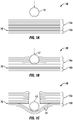
- Behavior of a composite article may be described in three general categories.
- a composite 10 includes layers 14a/14b, which may be individual plies or groups of plies, about to be impacted by object 12.
- Composite 10 includes frontside layers 14a separated from backside layers 14b by a region of reduced adhesion 16. Frontside layers 14a are outer layers of a structure and would be impacted before backside layers 14b.
- Fig. 1B shows object 12 impacting frontside layers 14a and traveling through them.
- the methods and apparatuses described herein for distributing the load from the force of kinetic energy from object 12 may be utilized.
- layers 14a, 14b, or both may include designated patterns sufficient to measureably vary adhesion, toughness, strength, modulus, or combinations thereof.
- Fig. 1C shows backside layers 14b becoming catching layers 18 as they delaminate and release from contact with frontside layers 14a.
- backside layers 14b may be released, enabling various energy absorption mechanisms.
- shearing of reduced adhesion 16 absorbs kinetic energy.
- the shear performance between backside layers 14b as they become catching layers 18 can be controlled to allow shearing between such layers.
- the shearing between catching layers 18 promotes free movement of catching layers 18 and additionally absorbs kinetic energy.
- breach of the structure may be avoided by relying on a mechanism instead of or in addition to load distribution in the methods and apparatuses herein.
- a variety of self-sealing fuel bladders are known. They operate according to various mechanisms whereby exposure of fibers and/or plies sets in motion physical changes to a ruptured area, reducing fuel loss.
- partial delamination of catching layers 18 could allow migration of liquid, such as fuel, into the delamination, setting in motion the mechanisms that self-seal the fuel bladder, such as swelling, foaming, etc. of the delaminated fibers and/or plies.
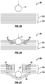
- Figs. 2A-2C explain a measure that may be used alone or in conjunction with the catching layer concept of Figs. 1A-1C .
- Figs. 2A-2C show the measure used in conjunction with the catching layer concept.
- a composite 20 includes layers 24a/24b, which may be individual plies or groups of plies, about to be impacted by object 12.
- Composite 20 includes frontside layers 24a separated from backside layers 24b.
- the region of reduced adhesion 16 in Figs. 1A-1C may be included in composite 20 to separate frontside layers 24a from backside layers 24b.
- other forms of interface materials discussed herein may be included as a separator to yield catching layers 28.
- Fig. 2B shows object 12 impacting frontside layers 24a and traveling through them.
- the methods and apparatuses described herein for absorbing the kinetic energy from object 12 may be utilized.
- Micro-delaminations 26 are shown in Fig. 2B beginning to form.
- interface material between frontside layers 24a is patterned into regions of higher and lower adhesion.
- the lower adhesion is sufficiently low that the load applied from the kinetic energy of object 12 exceeds a separation threshold for the lower adhesion regions causing delaminations between the regions of higher adhesion.
- the micro-delaminations in lower adhesion regions distribute the width of the volume affected by the load applied to frontside layers 24a. The specific location of such lower adhesion regions is not apparent except that micro-delaminations 26 show where the distributed load exceeded a separation threshold sufficient to delaminate some of the lower adhesion regions.
- the varied adhesion can dictate the location and progression of delaminations.
- global deformation of the structure can be controlled.
- a specific mode may be targeted and a geometric structure variation designed to achieve the global failure mode. Examples include mode I (opening load) fracture toughness (GIC) and mode II (shearing load) fracture toughness (GIIC).
- the pattern variation may set the interface material characteristics to achieve one mode or the other.
- Another component of controlling global deformation may include controlling failure geometry.
- a specific geometry may be targeted and patterns that vary in the interface materials may be designed to achieve the failure geometry.
- One example includes an object impact that is expected to produce failure by symmetric deformation centered on the impact, but is altered by design to an asymmetric deformation, such as an elliptical deformation or deformation with more deformation to one side of the impacting object.
- Fig. 2C shows backside layers 24b becoming catching layers 28.
- the release properties associated with backside layers 24b also enables various energy absorption mechanisms, such as those described for catching layers 18.
- the designated patterns in composite 10 and 20 may measureably vary adhesion, toughness, strength, modulus, or combinations thereof through the thickness so that layers fail progressively. As object 12 passes through successive layers, failure of each layer absorbs kinetic energy additional to the other absorption mechanisms described. Accordingly, after delaminating from contact with frontside layers 14a or 24a, one or more plies in catching layers 18 or 28 may fail progressively. One or more other plies may remain to avoid breach of the structure. In this manner, layers 14b or 24b absorb additional kinetic energy after becoming catching layers 18 or 28.
- self-sealing fuel bladders may be incorporated into composite 20. Since self-sealing fuel bladders often operate on the assumption that fibers will fail and layers will be delaminated, increasing the distribution of the damage mechanism, as in micro-delaminations 26, may initiate a more significant response in the known self-sealing mechanisms. Delamination may allow fluid, such as fuel, ingress into layers 24a and cause the reaction or physical response in a self-sealing mechanism. Similarly, such delamination may accentuate, release, or mix chemical species to cause foaming and/or local expansion and cure with the purpose of plugging breaches in composite 20.
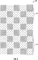
- Fig. 3 shows a top view of an interface material geometric structure providing in-plane variation of properties, such as adhesion, toughness, strength, modulus, or combinations thereof.
- the geometric structure could be printed using known methods and apparatuses, or applied by another known technique.
- a pattern 30 in Fig. 3 contains regions of higher density 32 and regions of lower density 34. Disks of interface material within higher density regions 32 are distributed to yield a desired coverage area while the interface material disks in lower density regions 34 have a coverage area lower than the coverage area of regions 32.
- the interface material disks could contain an adhering species or, alternatively, a releasing species. For adhering species, higher density regions 32 would exhibit a higher level of adhesion compared to lower density regions 34. For releasing species, higher density regions 32 would exhibit a lower level of adhesion compared to lower density regions 34.
- a composite 40 includes layers 44 that alternate between A-type and B-type.
- the dashed lines of the B-type of layers 44 are not intended necessarily to indicate intermittent coverage of interface material. Instead, the dashed lines merely identify a different type of interface material. Intermittent coverage is one way to provide differing types of interface material.
- Fig. 4 could provide the A-type of layers 44 with a higher adhesion level compared to the B-type of layers 44, such that the B-type layers preferentially delaminate.
- properties may vary in the through-thickness direction.
- other through-thickness regions of composite 40 not visible in Fig. 4 could be provided that do not vary in the through-thickness region of layers 44 or that vary differently than shown in Fig. 4 .
- a pattern could be provided in the through-thickness region as well as in-plane.
- the B-type of layers 44 could be replaced with the A-type of layers 44 in other through-thickness regions not shown in Fig. 4 .
- Fig. 5 shows another cross-sectional side view of another example of spatial variation among layers of interface material.
- Fig. 5 shows an ABCABC variation by adding a C-type of interface material among layers 54.
- the dashed line of C-type layers 54 merely shows a different type of interface material, not an interface material of necessarily different coverage area, although that is one type of possible variation.
- Other conceivable variations include an AABBAABB pattern, an ABCCBAABCCBA pattern, etc.
- Figs. 4 and 5 provide another mechanism for controlling performance of reinforced composite materials in keeping with the methods and apparatuses described herein.
- the plies themselves are not apparent, but layers 44 and 54 of interface material are understood to be positioned between plies of composites 40 and 50.
- Figs. 1A-1C , 2A-2C , and 3-5 provide a few possibilities for patterning an adhesive, a coupling agent, a release agent, or some other interface material effective to control the failure mode between layers of plies or between individual plies themselves.
- additional possibilities for achieving a desired failure mode are conceivable when taking into account the following additional considerations.
- a few non-exclusive examples of desired failure modes include a) controlling the amount of energy absorbed during release of a layer, b) controlling the amount of energy absorbed specifically through delamination of layers, c) controlling the amount of energy absorbed by the type of delamination, such as micro-delaminations, and d) controlling the amount of energy absorbed by release of backside layers into a catch layer.
- Interrelated properties of interface material that influence achieving the enumerated failure modes and other failure modes include material property variation, geometric structure variation, spatial variation, and combinations thereof.
- Material property variation may be variation in an adhesive, coupling agent, or release agent. Properties may vary by material composition so that providing different compositions of interface material in-plane or through-thickness yields the desired variation. For some materials, the manufacturing method may also influence properties such as adhesion, toughness, strength, and modulus although the material has the same composition. In addition, different categories of interface material may be used in-plane or through-thickness, such as, alternating adhesive and release agent. Consequently, although complete coverage of an interface material may exist between layers, material properties may vary in-plane or through-thickness.
- geometric structure variation may introduce regions that perform differently to provide the desired control of failure modes. It is conceivable that geometric structure variation may be used to create a pattern of regions with controlled mechanical properties, such as, adhesion/release, energy absorption, delamination area, and delamination pattern/direction. In geometric structure variation, generally speaking, the presence or absence of a given interface material determines the properties. Material property variation may be combined with geometric structure variation so that different interface materials are distributed among a pattern of geometric structure. Patterns may use a variety of geometric forms, such as squares, circles, ellipses, triangles, stars, rectangles, lines, squiggles, random patterns, and combinations thereof.
- Interface material films such as non-woven films, are amenable to production with patterns of geometric structure variation formed therein.
- One simple example includes lines of adhesive spaced apart in-plane to yield a desired effect.
- Material property variation may be introduced by including two-types of adhesive, A and B in a repeating pattern. Width of lines may be additionally varied to introduce a second geometric structure variation.
- lines of adhesive spaces between lines need not be present when multiple types of interface material are included in the interface material.
- the variations discussed above for Figs. 4 and 5 of ABAB, ABCABC, AABBAABB, ABCCBAABCCBA, etc. may be implemented in-plane with different film types and/or spaces.
- Geometric structure variation may be discussed in the context of the percentage of an area covered by interface material. Additionally, it is expected that different geometric forms used in geometric structure variation may influence failure modes even for interface materials of the same coverage area.
- Spatial variation may occur between layers of a structure at specific locations in the through-thickness direction and/or over the in-plane direction to provide the ability to tailor the location of specific energy absorption and/or failure modes spatially throughout an article.
- Certain parts of an article serve certain purposes and spatial variation allows varying a pattern to match features of select locations on a specific article, such as having high adhesion near article edges.
- One example of spatial variation is described above with regard to Figs. 1C and 2C .
- Fabrication considerations allow a variety of methods for making the apparatuses described herein. Advances in material printing technology enable the material property variation, geometric structure variation, and spatial variation described herein. Material printing technology enables a wide variety of printed pattern options for interface material compatible with material printing. One benefit of the material property variation, geometric structure variation, and spatial variation includes ease of implementation prior to matrix impregnation ("prepregging") or during panel layup.
- prepregging matrix impregnation
- Patterned toughener film, release film, veil, or other interface material may be applied during fabrication and/or prepregging. Veils are normally used to enhance surface appearance and/or duration by masking the reinforcing fiber pattern. However, herein, veils may be used as interface material. As interface materials, veils may be made with material property variations (different fibers, different adhesives, multiple fibers, different adhesives in patterns, etc). Veils may include geometric structure variations, such as, holes in different patterns, different percentages of coverage, different shapes, etc. Veils may include spatial variation, such as, the thickness of the veil (locally thick regions, locally thin regions, etc). The amount of adhesion between the fibers of the veils may vary spatially. The fibers in the veil may be oriented either globally or locally.
- Additional features may be printed directly on layers used to compose an article.
- the variations may be introduced in-line during fabrication of a part, during fabrication of a film, or during fabrication of prepreg articles.
- Alternatives to material printing include spraying through a mask and placing a patterned film or other non-woven interface material in the structure.
- the film or non-woven interface material could have holes in it or selected regions with properties different from other regions. Simply placing the film or non-woven interface material then introduces the variation.
- a kinetic energy absorption method includes providing a reinforced composite article including a first ply, a second ply other than the first ply, and a third ply other than the first and second plies.
- a first interface material is between the first ply and the second ply.
- a second interface material is between the second ply and the third ply.
- a designated pattern of material property variation, geometric structure variation, spatial variation, or combinations thereof is distributed to selected locations identified in the first interface material or distributed between selected locations identified in the first interface material compared to the second interface material. The pattern is sufficient to measurably vary adhesion, toughness, strength, modulus, or combinations thereof.
- a matrix material at least partially encapsulates the first, second, and third plies.
- the method additionally includes distributing a load across the pattern when the first, second, and third plies receive a force from kinetic energy above a separation threshold by partially delaminating the first ply from the second ply, the second ply from the third ply, or both.
- adhesion refers to a widely-known property describing the tendency of surfaces to cling to one another.
- toughness refers to a widely-known property wherein a material absorbs energy without fracturing, even though it may plastically deform. In some systems, toughness may be quantified as the total area under the stress-strain curve. Further, “strength” refers to the ability of a material to avoid failure while withstanding an applied stress. In some systems, strength may be quantified as the ultimate tensile strength, meaning the maximum engineering (i.e., nominal) stress of the stress-strain curve.
- modulus (i.e., “elastic modulus”) describes the ability of a material to resist elastic deformation.
- modulus may be quantified as the slope of the stress-strain curve in the elastic region. Adhesion, toughness, strength, and modulus may be measured by a variety of techniques known to those of ordinary skill.
- the article may be an aircraft fuel bladder.
- the first interface material may contact both the first ply and the second ply.
- the second interface material may contact both the second ply and the third ply.
- the composite article may be fiber-reinforced and the first, second, and third plies may be plies of fibers.
- the composite article may be film-reinforced and the first, second, and third plies may be plies of film.
- the first and second interface materials may independently contain a material selected from among an adhesive, a coupling agent, a release agent, a polymer film, an adhesive film, a toughener film, a release film, a veil, or combinations thereof.
- the adhesive film, the toughener film, and the release film may be non-woven films.
- the pattern may include a geometric structure selected from among squares, circles, ellipses, triangles, stars, rectangles, lines, squiggles, random patterns, and combinations thereof.
- the first interface material may contain a pattern of multiple first regions of interface material disks, wherein each of the multiple first regions has a coverage area.
- the first interface material may also include a pattern of multiple second regions of interface material disks, wherein each of the multiple second regions has a coverage area lower than the coverage area of the first regions.
- the pattern may be a first pattern and the article may further include a designated second pattern of material property variation, geometric structure variation, spatial variation, or combinations thereof distributed to selected locations identified in the second interface material.
- the second pattern may be sufficient to measurably vary adhesion, toughness, strength, modulus, or combinations thereof to a different degree than the first pattern.
- the method may further include distributing the load across the first and second patterns by partially delaminating the first ply from the second ply and the second ply from the third ply.
- the composite article may further include a fourth ply other than the first, second, and third plies, a third interface material between the third ply and the fourth ply, a designated third pattern of material property variation, geometric structure variation, spatial variation, or combinations thereof distributed to selected locations identified in the third interface material.
- the third pattern may be sufficient to measurably vary adhesion, toughness, strength, modulus, or combinations thereof to a different degree than the second patterns.
- the method may further include distributing the load across the first, second, and third patterns by additionally partially delaminating the third ply from the fourth ply.
- the third ply may be a backside ply, another designated pattern may be distributed in the second interface material, the second interface material may be a release material, and the second interface material may contact both the second ply and the third ply. It follows then that the distribution of the load may further include applying the load with an object having kinetic energy, catching the object with the third ply after it passes through the first ply, and partially delaminating the third ply from the second ply.
- the second and third plies may be backside plies
- the first interface material may be a release material
- the first interface material may contact both the first ply and the second ply.
- Another designated pattern may be distributed in the second interface material
- the second interface material may be a shearing material
- the second interface material may contact both the second ply and the third ply. Consequently, the distribution of the load may further include applying the load with an object having kinetic energy and catching the object with the second and third plies after it passes through the first ply.
- the second ply may be partially delaminated from first ply.
- the method includes promoting free movement between the second and third plies by shearing the second interface material.
- a kinetic energy absorptive, reinforced, composite article contains a first ply, a second ply other than the first ply, and a third ply other than the first and second plies.
- a first interface material is between the first ply and the second ply.
- a second interface material is between the second ply and the third ply.
- the article includes a designated pattern of material property variation, geometric structure variation, spatial variation, or combinations thereof distributed to selected locations identified in the first interface material or distributed between selected locations identified in the first interface material compared to the second interface material. The pattern is sufficient to measurably vary adhesion, toughness, strength, modulus, or combinations thereof.
- a matrix material at least partially encapsulates the first, second, and third plies.
- the article may be an aircraft fuel bladder.
- the first interface material may contact both the first ply and the second ply.
- the second interface material may contact both the second ply and the third ply.
- the composite article may be fiber-reinforced and the first, second, and third plies may be plies of fibers.
- the composite article may be film-reinforced and the first, second, and third plies may be plies of film.
- the first and second interface materials may independently contain a material selected from among an adhesive, a coupling agent, a release agent, a polymer film, an adhesive film, a toughener film, a release film, a veil, and combinations thereof.
- the adhesive film, the toughener film, and the release film may be non-woven films.
- the pattern may include a geometric structure selected from among squares, circles, ellipses, triangles, stars, rectangles, lines, squiggles, random patterns, and combinations thereof.
- the first interface material may contain a pattern of multiple first regions of interface material disks, wherein each of the multiple first regions have a coverage area.
- the first interface material may also include a pattern of multiple second regions of interface material disks, wherein each of the multiple second regions have a coverage area lower than the coverage area of the first regions.
- the pattern may be a first pattern and the article may further contain a designated second pattern of material property variation, geometric structure variation, spatial variation, or combinations thereof distributed to selected locations identified in the second interface material.
- the second pattern may be sufficient to measurably vary adhesion, toughness, strength, modulus, or combinations thereof to a different degree than the first pattern.
- the composite article may further contain a fourth ply other than the first, second, and third plies, and a third interface material between the third ply and the fourth ply.
- the article may further include a designated third pattern of material property variation, geometric structure variation, spatial variation, or combinations thereof distributed to selected locations identified in the third interface material.
- the third pattern may be sufficient to measurably vary adhesion, toughness, strength, modulus, or combinations thereof to a different degree than the first and second patterns.
- the third ply may be a backside ply, another designated pattern may be distributed in the second interface material, the second interface material may be a release material, and the second interface material may contact both the second ply and the third ply.
- the second and third plies may be backside plies
- the first interface material may be a release material
- the first interface material may contact both the first ply and the second ply.
- Another designated pattern may be distributed in the second interface material
- the second interface material may be a shearing material
- the second interface material may contact both the second ply and the third ply.
- a kinetic energy absorptive, reinforced, composite article includes an interior ply, a first backside ply other than the interior ply, and a second backside ply other than the interior ply and the first backside ply.
- a release material is between and in contact with the interior ply and the first backside ply.
- a shearing material is between and in contact with the first backside ply and the second backside ply.
- the article includes a designated first pattern of material property variation, geometric structure variation, spatial variation, or combinations thereof distributed to selected locations identified in the release material. The first pattern is sufficient to measurably vary adhesion, toughness, strength, modulus, or combinations thereof.
- the article includes a designated second pattern of material property variation, geometric structure variation, spatial variation, or combinations thereof distributed to selected locations identified in the shearing material.
- the second pattern is sufficient to measurably vary adhesion, toughness, strength, modulus, or combinations thereof to a different degree than the first pattern.
- a matrix material at least partially encapsulates the interior ply, the first backside ply, and the second backside ply.
- the composite article may be fiber-reinforced and the first, second, and third plies may be plies of fibers.
- the composite article may be film-reinforced and the first, second, and third plies may be plies of film.
- the additional features that may be implemented in the present article may also be implemented in other examples herein.
Landscapes
- Engineering & Computer Science (AREA)
- Aviation & Aerospace Engineering (AREA)
- Chemical & Material Sciences (AREA)
- Composite Materials (AREA)
- Mechanical Engineering (AREA)
- Laminated Bodies (AREA)
- Reinforced Plastic Materials (AREA)
- Moulding By Coating Moulds (AREA)
- Combustion & Propulsion (AREA)
- Remote Sensing (AREA)
Claims (12)
- Kinetische Energie absorbierender, verstärkter Verbundartikel (10, 20), umfassend:eine erste Lage, eine zweite Lage, die von der ersten Lage verschieden ist, und eine dritte Lage, die von der ersten und zweiten Lage verschieden ist;ein erstes Grenzflächenmaterial zwischen der ersten Lage und der zweiten Lage;ein zweites Grenzflächenmaterial zwischen der zweiten Lage und der dritten Lage;ein festgelegtes Muster (30, 44, 54) von Materialeigenschaftsvariationen, geometrischen Strukturvariationen, räumlichen Variationen oder Kombinationen davon im Vergleich zu dem zweiten Grenzflächenmaterial, verteilt auf in dem ersten Grenzflächenmaterial identifizierte ausgewählte Stellen oder verteilt zwischen in dem ersten Grenzflächenmaterial identifizierten ausgewählten Stellen;wobei das Muster ausreicht, um Adhäsion, Zähigkeit, Festigkeit, Modul oder Kombinationen davon messbar zu verändern; undein Matrixmaterial, das die ersten, zweiten und dritten Lagen zumindest teilweise einkapselt;wobei die zweite und dritte Lage Rückseitenlagen (14b, 24b) sind, das erste Grenzflächenmaterial ein Trennmaterial (16) ist, das erste Grenzflächenmaterial sowohl die erste Lage als auch die zweite Lage berührt, ein anderes festgelegtes Muster in dem zweiten Grenzflächenmaterial verteilt ist, das zweite Grenzflächenmaterial ein Schermaterial ist, und das zweite Grenzflächenmaterial sowohl die zweite Lage als auch die dritte Lage berührt.
- Artikel nach Anspruch 1, wobei der Artikel eine Flugzeugkraftstoffblase ist.
- Artikel nach Anspruch 1 oder 2, bei dem das erste Grenzflächenmaterial sowohl die erste Lage als auch die zweite Lage berührt und das zweite Grenzflächenmaterial sowohl die zweite Lage als auch die dritte Lage berührt.
- Artikel nach einem der Ansprüche 1 - 3, wobei:der Verbundartikel faserverstärkt ist und die ersten, zweiten und dritten Lagen Lagen aus Fasern sind, oder der Verbundartikel folienverstärkt ist und die ersten, zweiten und dritten Lagen Lagen aus Folie sind; unddie ersten und zweiten Grenzflächenmaterialien unabhängig voneinander ein Material umfassen, das aus einem Klebstoff, einem Haftvermittler, einem Trennmittel, einer Polymerfolie, einer nicht gewebten Klebstofffolie, einer nicht gewebten zähmachenden Folie, einer nicht gewebten Trennfolie, einem Schleier und Kombinationen davon ausgewählt ist.
- Artikel nach einem der Ansprüche 1 - 4, bei dem das Muster eine geometrische Struktur umfasst, die aus Quadraten, Kreisen, Ellipsen, Dreiecken, Sternen, Rechtecken, Linien, Schnörkeln, Zufallsmustern und Kombinationen davon ausgewählt ist.
- Artikel nach einem der Ansprüche 1 - 5, bei dem das erste Grenzflächenmaterial ein Muster aus mehreren ersten Bereichen (32) von Grenzflächenmaterialscheiben, wobei jeder der mehreren ersten Bereiche einen Abdeckungsbereich aufweist, und ein Muster aus mehreren zweiten Bereichen (34) von Grenzflächenmaterialscheiben umfasst, wobei jeder der mehreren zweiten Bereiche eine Flächenabdeckung aufweist, die geringer ist als die Flächenabdeckung der ersten Bereiche.
- Artikel nach einem der Ansprüche 1 - 6, bei dem das Muster ein erstes Muster ist und das andere festgelegte Muster ein zweites Muster von Materialeigenschaftsvariationen, geometrischen Strukturvariationen, räumlichen Variationen oder Kombinationen davon ist, die auf in dem zweiten Grenzflächenmaterial identifizierte ausgewählte Stellen verteilt sind; und
bei dem das zweite Muster ausreicht, um Adhäsion, Zähigkeit, Festigkeit, Modul oder Kombinationen davon in einem anderen Ausmaß als das erste Muster messbar zu verändern. - Artikel nach Anspruch 7, wobei der Verbundartikel weiterhin umfasst:eine vierte Lage, die von der ersten, zweiten und dritten Lage verschieden ist;ein drittes Grenzflächenmaterial zwischen der dritten Lage und der vierten Lage;ein festgelegtes drittes Muster von Materialeigenschaftsvariationen, geometrischen Strukturvariationen, räumlichen Variationen oder Kombinationen davon, die auf in dem dritten Grenzflächenmaterial identifizierte ausgewählte Stellen verteilt sind; undwobei das dritte Muster ausreicht, um Adhäsion, Zähigkeit, Festigkeit, Modul oder Kombinationen davon in einem anderen Ausmaß als das erste und zweite Muster messbar zu verändern.
- Verfahren zum Absorbieren von kinetischer Energie unter Verwendung eines verstärkten Verbundartikels (10, 20), der umfasst:eine erste Lage, eine zweite Lage, die von der ersten Lage verschieden ist, und eine dritte Lage, die von der ersten und zweiten Lage verschieden ist;ein erstes Grenzflächenmaterial zwischen der ersten Lage und der zweiten Lage;ein zweites Grenzflächenmaterial zwischen der zweiten Lage und der dritten Lage;ein festgelegtes Muster (30, 44, 54) von Materialeigenschaftsvariationen, geometrischen Strukturvariationen, räumlichen Variationen oder Kombinationen davon im Vergleich zu dem zweiten Grenzflächenmaterial, verteilt auf in dem ersten Grenzflächenmaterial identifizierte ausgewählte Stellen oder verteilt zwischen in dem ersten Grenzflächenmaterial identifizierten ausgewählten Stellen;wobei das Muster ausreicht, um Adhäsion, Zähigkeit, Festigkeit, Modul oder Kombinationen davon messbar zu verändern; undein Matrixmaterial, das die ersten, zweiten und dritten Lagen zumindest teilweise einkapselt;wobei das Verfahren umfasst:Verteilen einer Last über das Muster, wenn die erste, zweite und dritte Lage eine Kraft aus kinetischer Energie oberhalb einer Trennungsschwelle erhalten, durch teilweises Delaminieren der ersten Lage von der zweiten Lage, der zweiten Lage von der dritten Lage oder von beiden;wobei die zweite und die dritte Lage Rückseitenlagen (14b, 24b) sind, das erste Grenzflächenmaterial ein Trennmaterial (16) ist, das erste Grenzflächenmaterial sowohl die erste Lage als auch die zweite Lage berührt, ein anderes festgelegtes Muster in dem zweiten Grenzflächenmaterial verteilt ist, das zweite Grenzflächenmaterial ein Schermaterial ist, und das zweite Grenzflächenmaterial sowohl die zweite Lage als auch die dritte Lage berührt; undwobei das Verteilen der Last ferner umfasst:Aufbringen der Last mit einem Objekt (10), das kinetische Energie hat;Auffangen des Objekts mit der zweiten und dritten Lage, nachdem es die erste Lage passiert hat;teilweises Delaminieren der zweiten Lage von der ersten Lage; undördern der freien Bewegung zwischen der zweiten und dritten Lage durch Abscheren des zweiten Grenzflächenmaterials.
- Verfahren nach Anspruch 9, bei dem:(a) der Verbundartikel faserverstärkt ist und die ersten, zweiten und dritten Lagen Lagen aus Fasern sind, oder der Verbundartikel folienverstärkt ist und die ersten, zweiten und dritten Lagen Lagen aus Folie sind; und die ersten und zweiten Grenzflächenmaterialien unabhängig voneinander ein Material umfassen, das aus einem Klebstoff, einem Haftvermittler, einem Trennmittel, einer Polymerfolie, einer Klebefolie, einer zähmachenden Folie, einer Trennfolie, einem Schleier oder Kombinationen davon ausgewählt ist;(b) das Muster eine geometrische Struktur umfasst, die aus Quadraten, Kreisen, Ellipsen, Dreiecken, Sternen, Rechtecken, Linien, Schnörkeln, Zufallsmustern und Kombinationen davon ausgewählt ist;(c) das erste Grenzflächenmaterial ein Muster aus mehreren ersten Bereichen (32) von Grenzflächenmaterialscheiben, wobei jeder der mehreren ersten Bereiche eine Flächenabdeckung aufweist, und ein Muster aus mehreren zweiten Bereichen (34) von Grenzflächenmaterialscheiben umfasst, wobei jeder der mehreren zweiten Bereiche eine Flächenabdeckung aufweist, die geringer ist als die Flächenabdeckung der ersten Bereiche;oder eine beliebige Kombination von (a), (b) und (c).
- Verfahren nach Anspruch 9 oder 10, bei dem:das Muster ein erstes Muster ist und das andere festgelegte Muster ein zweites Muster von Materialeigenschaftsvariationen, geometrischen Strukturvariationen, räumlichen Variationen oder Kombinationen davon ist, die auf in dem zweiten Grenzflächenmaterial identifizierte ausgewählte Stellen verteilt sind; unddas zweite Muster ausreicht, um Adhäsion, Zähigkeit, Festigkeit, Modul oder Kombinationen davon in einem anderen Ausmaß als das erste Muster messbar zu verändern; unddas Verfahren ferner umfasst:
Verteilen der Last über das erste und zweite Muster durch teilweises Delaminieren der ersten Lage von der zweiten Lage und der zweiten Lage von der dritten Lage. - Verfahren nach Anspruch 11, bei dem der Verbundartikel weiterhin umfasst:eine vierte Lage, die von der ersten, zweiten und dritten Lage verschieden ist;ein drittes Grenzflächenmaterial zwischen der dritten Lage und der vierten Lage;ein festgelegtes drittes Muster von Materialeigenschaftsvariationen, geometrischen Strukturvariationen, räumlichen Variationen oder Kombinationen davon, die auf in dem dritten Grenzflächenmaterial identifizierte ausgewählte Stellen verteilt sind; und
wobei das dritte Muster ausreicht, um Adhäsion, Zähigkeit, Festigkeit, Modul oder Kombinationen davon in einem anderen Ausmaß als das erste und das zweite Muster messbar zu verändern; unddas Verfahren ferner umfasst:
Verteilen der Last über das erste, zweite und dritte Muster durch zusätzliches teilweises Delaminieren der dritten Lage von der vierten Lage.
Applications Claiming Priority (1)
| Application Number | Priority Date | Filing Date | Title |
|---|---|---|---|
| US15/904,958 US10974841B2 (en) | 2018-02-26 | 2018-02-26 | Kinetic energy absorption method and kinetic energy absorptive, reinforced, composite article |
Publications (2)
| Publication Number | Publication Date |
|---|---|
| EP3530443A1 EP3530443A1 (de) | 2019-08-28 |
| EP3530443B1 true EP3530443B1 (de) | 2021-06-16 |
Family
ID=64664051
Family Applications (1)
| Application Number | Title | Priority Date | Filing Date |
|---|---|---|---|
| EP18210688.0A Active EP3530443B1 (de) | 2018-02-26 | 2018-12-06 | Bewegungsenergie-absorptionsverfahren und bewegungsenergie-absorptionsfähiger, verstärkter verbundartikel |
Country Status (6)
| Country | Link |
|---|---|
| US (1) | US10974841B2 (de) |
| EP (1) | EP3530443B1 (de) |
| JP (1) | JP7250561B2 (de) |
| CN (1) | CN110194271B (de) |
| AU (1) | AU2018264143B2 (de) |
| CA (1) | CA3025241C (de) |
Families Citing this family (6)
| Publication number | Priority date | Publication date | Assignee | Title |
|---|---|---|---|---|
| US11376812B2 (en) | 2020-02-11 | 2022-07-05 | Helicoid Industries Inc. | Shock and impact resistant structures |
| US12275227B2 (en) | 2020-02-11 | 2025-04-15 | Helicoid Industries, Inc. | Composite materials and structures |
| US11346499B1 (en) | 2021-06-01 | 2022-05-31 | Helicoid Industries Inc. | Containers and methods for protecting pressure vessels |
| US11852297B2 (en) | 2021-06-01 | 2023-12-26 | Helicoid Industries Inc. | Containers and methods for protecting pressure vessels |
| CA3260537A1 (en) | 2022-06-27 | 2024-01-04 | Helicoid Industries Inc. | Reinforced fiber resistant to significant impacts for leading edge protection of aerodynamic structures |
| CN115489742B (zh) * | 2022-10-27 | 2024-08-09 | 芜湖中科飞机制造有限公司 | 一种教练机用燃油防晃机构 |
Family Cites Families (17)
| Publication number | Priority date | Publication date | Assignee | Title |
|---|---|---|---|---|
| US3958055A (en) | 1974-08-14 | 1976-05-18 | Kimberly-Clark Corporation | Adhesive bonding of isotropic fiber webs to form pattern bonded composites |
| AU672677B2 (en) * | 1993-01-21 | 1996-10-10 | United Technologies Corporation | Pressure tolerant fuel tank panels |
| AU5584898A (en) * | 1996-11-15 | 1998-06-03 | Brigham Young University | Damped composite structures with fiber wave patterns and method and apparatus for making same |
| JP2006515809A (ja) * | 2001-09-17 | 2006-06-08 | ヴェルダント テクノロジーズ インコーポレイテッド | 三次元ニットスペーサ織物サンドイッチ複合体 |
| JP4247038B2 (ja) | 2003-04-25 | 2009-04-02 | 三菱重工業株式会社 | 衝撃吸収複合材構造及びその製造方法並びにそれを用いた走行体又は航行体 |
| JP2009078422A (ja) * | 2007-09-26 | 2009-04-16 | Toray Ind Inc | 制振性繊維強化複合材料 |
| GB201003592D0 (en) * | 2010-03-04 | 2010-04-21 | Rolls Royce Plc | A component comprising a resin matrix |
| US9857148B2 (en) * | 2010-12-15 | 2018-01-02 | The Boeing Company | Controlled fiber-matrix adhesion in polymer fiber composites |
| US8796164B2 (en) * | 2010-12-28 | 2014-08-05 | Cytec Technology Corp. | Multilayer and composition gradient structures with improved damping properties |
| US10005256B2 (en) | 2012-06-14 | 2018-06-26 | The Boeing Company | Selectively weakened stretched films |
| US10343372B2 (en) | 2014-07-03 | 2019-07-09 | Saab Ab | Composite article having multifunctional properties and method for its manufacture |
| US9845556B2 (en) * | 2014-09-23 | 2017-12-19 | The Boeing Company | Printing patterns onto composite laminates |
| US9597859B2 (en) | 2015-05-27 | 2017-03-21 | The Boeing Company | Self-sealing bladders and related methods |
| US10457138B2 (en) | 2015-09-02 | 2019-10-29 | The Boeing Company | Self-sealing liquid bladders |
| US10124664B2 (en) | 2015-09-02 | 2018-11-13 | The Boeing Company | Self-sealing liquid bladders |
| US9809109B2 (en) | 2015-09-02 | 2017-11-07 | The Boeing Company | Ballooning self-sealing bladders |
| US9925863B2 (en) | 2015-09-02 | 2018-03-27 | The Boeing Company | Self-sealing liquid bladders |
-
2018
- 2018-02-26 US US15/904,958 patent/US10974841B2/en not_active Expired - Fee Related
- 2018-11-16 AU AU2018264143A patent/AU2018264143B2/en not_active Ceased
- 2018-11-23 CA CA3025241A patent/CA3025241C/en active Active
- 2018-12-06 EP EP18210688.0A patent/EP3530443B1/de active Active
- 2018-12-19 CN CN201811552202.1A patent/CN110194271B/zh not_active Expired - Fee Related
-
2019
- 2019-02-21 JP JP2019028992A patent/JP7250561B2/ja active Active
Also Published As
| Publication number | Publication date |
|---|---|
| US20190263532A1 (en) | 2019-08-29 |
| EP3530443A1 (de) | 2019-08-28 |
| US10974841B2 (en) | 2021-04-13 |
| JP7250561B2 (ja) | 2023-04-03 |
| JP2019196166A (ja) | 2019-11-14 |
| CA3025241A1 (en) | 2019-08-26 |
| CN110194271A (zh) | 2019-09-03 |
| AU2018264143B2 (en) | 2023-12-21 |
| CA3025241C (en) | 2022-10-25 |
| CN110194271B (zh) | 2024-06-11 |
| BR102018077406A2 (pt) | 2019-11-05 |
| AU2018264143A1 (en) | 2019-09-12 |
Similar Documents
| Publication | Publication Date | Title |
|---|---|---|
| EP3530443B1 (de) | Bewegungsenergie-absorptionsverfahren und bewegungsenergie-absorptionsfähiger, verstärkter verbundartikel | |
| EP2363271B1 (de) | Mehrlagiges Komponent mit Trennmaterial zwischen den Lagen | |
| US8450225B2 (en) | Structural composite material with improved acoustic and vibrational damping properties | |
| JP5011613B2 (ja) | プリフォームおよび成形方法 | |
| EP3318481B1 (de) | Plattenstruktur für ein flugzeug und herstellungsverfahren dafür | |
| FI101870B (fi) | Paineaaltoa ja murtokappaleita absorboiva yhdistelmämateriaali, joka s opii erityisesti lentokonerakenteiden suojaamiseksi räjähdystilanteiss a | |
| EP2788183B1 (de) | Faserverstärktes verbundmaterial mit verbesserter feuerbeständigkeit und daraus hergestellte strukturkomponente | |
| JP2019206171A (ja) | エネルギーを吸収する複合パネル | |
| CN103373011A (zh) | 具有纵向变化几何形状的纤维的复合制品 | |
| US10994514B2 (en) | Kinetic energy absorption method | |
| Ali et al. | Damage evolution in glass/epoxy composites engineered using core–shell microparticles under impact loading | |
| US6647856B1 (en) | Turbine compressor armor shield | |
| BR102018077406B1 (pt) | Método de absorção de energia cinética e artigo composto, reforçado, absorvente de energia cinética | |
| NL2024672B1 (en) | Aircraft Structural Panel | |
| JP2020006937A (ja) | 運動エネルギー吸収複合材物品及び吸収方法 | |
| DE4002062A1 (de) | Sekundaersplittergeschuetzter faserverstaerkter kunststoff | |
| US20040216594A1 (en) | Splinter resistant composite laminate | |
| AS | Institute for Structures and Design, DLR, Pfaffenwaldring 38-40, Stuttgart 80 | |
| Ray et al. | Lattice Core Sandwich Construction |
Legal Events
| Date | Code | Title | Description |
|---|---|---|---|
| PUAI | Public reference made under article 153(3) epc to a published international application that has entered the european phase |
Free format text: ORIGINAL CODE: 0009012 |
|
| STAA | Information on the status of an ep patent application or granted ep patent |
Free format text: STATUS: REQUEST FOR EXAMINATION WAS MADE |
|
| 17P | Request for examination filed |
Effective date: 20181206 |
|
| AK | Designated contracting states |
Kind code of ref document: A1 Designated state(s): AL AT BE BG CH CY CZ DE DK EE ES FI FR GB GR HR HU IE IS IT LI LT LU LV MC MK MT NL NO PL PT RO RS SE SI SK SM TR |
|
| AX | Request for extension of the european patent |
Extension state: BA ME |
|
| GRAP | Despatch of communication of intention to grant a patent |
Free format text: ORIGINAL CODE: EPIDOSNIGR1 |
|
| STAA | Information on the status of an ep patent application or granted ep patent |
Free format text: STATUS: GRANT OF PATENT IS INTENDED |
|
| INTG | Intention to grant announced |
Effective date: 20210119 |
|
| RIN1 | Information on inventor provided before grant (corrected) |
Inventor name: WILENSKI, MARK S Inventor name: KOZAR, MICHAEL P |
|
| GRAS | Grant fee paid |
Free format text: ORIGINAL CODE: EPIDOSNIGR3 |
|
| GRAA | (expected) grant |
Free format text: ORIGINAL CODE: 0009210 |
|
| STAA | Information on the status of an ep patent application or granted ep patent |
Free format text: STATUS: THE PATENT HAS BEEN GRANTED |
|
| AK | Designated contracting states |
Kind code of ref document: B1 Designated state(s): AL AT BE BG CH CY CZ DE DK EE ES FI FR GB GR HR HU IE IS IT LI LT LU LV MC MK MT NL NO PL PT RO RS SE SI SK SM TR |
|
| REG | Reference to a national code |
Ref country code: GB Ref legal event code: FG4D |
|
| REG | Reference to a national code |
Ref country code: DE Ref legal event code: R082 Ref document number: 602018018620 Country of ref document: DE Representative=s name: BOULT WADE TENNANT LLP, DE |
|
| REG | Reference to a national code |
Ref country code: CH Ref legal event code: EP |
|
| REG | Reference to a national code |
Ref country code: DE Ref legal event code: R096 Ref document number: 602018018620 Country of ref document: DE |
|
| REG | Reference to a national code |
Ref country code: AT Ref legal event code: REF Ref document number: 1401975 Country of ref document: AT Kind code of ref document: T Effective date: 20210715 |
|
| REG | Reference to a national code |
Ref country code: IE Ref legal event code: FG4D |
|
| REG | Reference to a national code |
Ref country code: LT Ref legal event code: MG9D |
|
| PG25 | Lapsed in a contracting state [announced via postgrant information from national office to epo] |
Ref country code: BG Free format text: LAPSE BECAUSE OF FAILURE TO SUBMIT A TRANSLATION OF THE DESCRIPTION OR TO PAY THE FEE WITHIN THE PRESCRIBED TIME-LIMIT Effective date: 20210916 Ref country code: FI Free format text: LAPSE BECAUSE OF FAILURE TO SUBMIT A TRANSLATION OF THE DESCRIPTION OR TO PAY THE FEE WITHIN THE PRESCRIBED TIME-LIMIT Effective date: 20210616 Ref country code: LT Free format text: LAPSE BECAUSE OF FAILURE TO SUBMIT A TRANSLATION OF THE DESCRIPTION OR TO PAY THE FEE WITHIN THE PRESCRIBED TIME-LIMIT Effective date: 20210616 Ref country code: HR Free format text: LAPSE BECAUSE OF FAILURE TO SUBMIT A TRANSLATION OF THE DESCRIPTION OR TO PAY THE FEE WITHIN THE PRESCRIBED TIME-LIMIT Effective date: 20210616 |
|
| REG | Reference to a national code |
Ref country code: AT Ref legal event code: MK05 Ref document number: 1401975 Country of ref document: AT Kind code of ref document: T Effective date: 20210616 |
|
| REG | Reference to a national code |
Ref country code: NL Ref legal event code: MP Effective date: 20210616 |
|
| PG25 | Lapsed in a contracting state [announced via postgrant information from national office to epo] |
Ref country code: SE Free format text: LAPSE BECAUSE OF FAILURE TO SUBMIT A TRANSLATION OF THE DESCRIPTION OR TO PAY THE FEE WITHIN THE PRESCRIBED TIME-LIMIT Effective date: 20210616 Ref country code: RS Free format text: LAPSE BECAUSE OF FAILURE TO SUBMIT A TRANSLATION OF THE DESCRIPTION OR TO PAY THE FEE WITHIN THE PRESCRIBED TIME-LIMIT Effective date: 20210616 Ref country code: NO Free format text: LAPSE BECAUSE OF FAILURE TO SUBMIT A TRANSLATION OF THE DESCRIPTION OR TO PAY THE FEE WITHIN THE PRESCRIBED TIME-LIMIT Effective date: 20210916 Ref country code: LV Free format text: LAPSE BECAUSE OF FAILURE TO SUBMIT A TRANSLATION OF THE DESCRIPTION OR TO PAY THE FEE WITHIN THE PRESCRIBED TIME-LIMIT Effective date: 20210616 Ref country code: GR Free format text: LAPSE BECAUSE OF FAILURE TO SUBMIT A TRANSLATION OF THE DESCRIPTION OR TO PAY THE FEE WITHIN THE PRESCRIBED TIME-LIMIT Effective date: 20210917 |
|
| PG25 | Lapsed in a contracting state [announced via postgrant information from national office to epo] |
Ref country code: EE Free format text: LAPSE BECAUSE OF FAILURE TO SUBMIT A TRANSLATION OF THE DESCRIPTION OR TO PAY THE FEE WITHIN THE PRESCRIBED TIME-LIMIT Effective date: 20210616 Ref country code: ES Free format text: LAPSE BECAUSE OF FAILURE TO SUBMIT A TRANSLATION OF THE DESCRIPTION OR TO PAY THE FEE WITHIN THE PRESCRIBED TIME-LIMIT Effective date: 20210616 Ref country code: SM Free format text: LAPSE BECAUSE OF FAILURE TO SUBMIT A TRANSLATION OF THE DESCRIPTION OR TO PAY THE FEE WITHIN THE PRESCRIBED TIME-LIMIT Effective date: 20210616 Ref country code: SK Free format text: LAPSE BECAUSE OF FAILURE TO SUBMIT A TRANSLATION OF THE DESCRIPTION OR TO PAY THE FEE WITHIN THE PRESCRIBED TIME-LIMIT Effective date: 20210616 Ref country code: NL Free format text: LAPSE BECAUSE OF FAILURE TO SUBMIT A TRANSLATION OF THE DESCRIPTION OR TO PAY THE FEE WITHIN THE PRESCRIBED TIME-LIMIT Effective date: 20210616 Ref country code: RO Free format text: LAPSE BECAUSE OF FAILURE TO SUBMIT A TRANSLATION OF THE DESCRIPTION OR TO PAY THE FEE WITHIN THE PRESCRIBED TIME-LIMIT Effective date: 20210616 Ref country code: PT Free format text: LAPSE BECAUSE OF FAILURE TO SUBMIT A TRANSLATION OF THE DESCRIPTION OR TO PAY THE FEE WITHIN THE PRESCRIBED TIME-LIMIT Effective date: 20211018 Ref country code: AT Free format text: LAPSE BECAUSE OF FAILURE TO SUBMIT A TRANSLATION OF THE DESCRIPTION OR TO PAY THE FEE WITHIN THE PRESCRIBED TIME-LIMIT Effective date: 20210616 Ref country code: CZ Free format text: LAPSE BECAUSE OF FAILURE TO SUBMIT A TRANSLATION OF THE DESCRIPTION OR TO PAY THE FEE WITHIN THE PRESCRIBED TIME-LIMIT Effective date: 20210616 |
|
| PG25 | Lapsed in a contracting state [announced via postgrant information from national office to epo] |
Ref country code: PL Free format text: LAPSE BECAUSE OF FAILURE TO SUBMIT A TRANSLATION OF THE DESCRIPTION OR TO PAY THE FEE WITHIN THE PRESCRIBED TIME-LIMIT Effective date: 20210616 |
|
| REG | Reference to a national code |
Ref country code: DE Ref legal event code: R097 Ref document number: 602018018620 Country of ref document: DE |
|
| PLBE | No opposition filed within time limit |
Free format text: ORIGINAL CODE: 0009261 |
|
| STAA | Information on the status of an ep patent application or granted ep patent |
Free format text: STATUS: NO OPPOSITION FILED WITHIN TIME LIMIT |
|
| PG25 | Lapsed in a contracting state [announced via postgrant information from national office to epo] |
Ref country code: DK Free format text: LAPSE BECAUSE OF FAILURE TO SUBMIT A TRANSLATION OF THE DESCRIPTION OR TO PAY THE FEE WITHIN THE PRESCRIBED TIME-LIMIT Effective date: 20210616 |
|
| 26N | No opposition filed |
Effective date: 20220317 |
|
| PG25 | Lapsed in a contracting state [announced via postgrant information from national office to epo] |
Ref country code: AL Free format text: LAPSE BECAUSE OF FAILURE TO SUBMIT A TRANSLATION OF THE DESCRIPTION OR TO PAY THE FEE WITHIN THE PRESCRIBED TIME-LIMIT Effective date: 20210616 |
|
| PG25 | Lapsed in a contracting state [announced via postgrant information from national office to epo] |
Ref country code: MC Free format text: LAPSE BECAUSE OF FAILURE TO SUBMIT A TRANSLATION OF THE DESCRIPTION OR TO PAY THE FEE WITHIN THE PRESCRIBED TIME-LIMIT Effective date: 20210616 Ref country code: IT Free format text: LAPSE BECAUSE OF FAILURE TO SUBMIT A TRANSLATION OF THE DESCRIPTION OR TO PAY THE FEE WITHIN THE PRESCRIBED TIME-LIMIT Effective date: 20210616 |
|
| REG | Reference to a national code |
Ref country code: CH Ref legal event code: PL |
|
| REG | Reference to a national code |
Ref country code: BE Ref legal event code: MM Effective date: 20211231 |
|
| PG25 | Lapsed in a contracting state [announced via postgrant information from national office to epo] |
Ref country code: LU Free format text: LAPSE BECAUSE OF NON-PAYMENT OF DUE FEES Effective date: 20211206 Ref country code: IE Free format text: LAPSE BECAUSE OF NON-PAYMENT OF DUE FEES Effective date: 20211206 |
|
| PG25 | Lapsed in a contracting state [announced via postgrant information from national office to epo] |
Ref country code: BE Free format text: LAPSE BECAUSE OF NON-PAYMENT OF DUE FEES Effective date: 20211231 |
|
| PG25 | Lapsed in a contracting state [announced via postgrant information from national office to epo] |
Ref country code: LI Free format text: LAPSE BECAUSE OF NON-PAYMENT OF DUE FEES Effective date: 20211231 Ref country code: CH Free format text: LAPSE BECAUSE OF NON-PAYMENT OF DUE FEES Effective date: 20211231 |
|
| P01 | Opt-out of the competence of the unified patent court (upc) registered |
Effective date: 20230516 |
|
| PG25 | Lapsed in a contracting state [announced via postgrant information from national office to epo] |
Ref country code: CY Free format text: LAPSE BECAUSE OF FAILURE TO SUBMIT A TRANSLATION OF THE DESCRIPTION OR TO PAY THE FEE WITHIN THE PRESCRIBED TIME-LIMIT Effective date: 20210616 |
|
| PG25 | Lapsed in a contracting state [announced via postgrant information from national office to epo] |
Ref country code: HU Free format text: LAPSE BECAUSE OF FAILURE TO SUBMIT A TRANSLATION OF THE DESCRIPTION OR TO PAY THE FEE WITHIN THE PRESCRIBED TIME-LIMIT; INVALID AB INITIO Effective date: 20181206 |
|
| PGFP | Annual fee paid to national office [announced via postgrant information from national office to epo] |
Ref country code: GB Payment date: 20231227 Year of fee payment: 6 |
|
| PGFP | Annual fee paid to national office [announced via postgrant information from national office to epo] |
Ref country code: FR Payment date: 20231227 Year of fee payment: 6 |
|
| PG25 | Lapsed in a contracting state [announced via postgrant information from national office to epo] |
Ref country code: MK Free format text: LAPSE BECAUSE OF FAILURE TO SUBMIT A TRANSLATION OF THE DESCRIPTION OR TO PAY THE FEE WITHIN THE PRESCRIBED TIME-LIMIT Effective date: 20210616 |
|
| PGFP | Annual fee paid to national office [announced via postgrant information from national office to epo] |
Ref country code: DE Payment date: 20231229 Year of fee payment: 6 |
|
| PG25 | Lapsed in a contracting state [announced via postgrant information from national office to epo] |
Ref country code: MT Free format text: LAPSE BECAUSE OF FAILURE TO SUBMIT A TRANSLATION OF THE DESCRIPTION OR TO PAY THE FEE WITHIN THE PRESCRIBED TIME-LIMIT Effective date: 20210616 |
|
| REG | Reference to a national code |
Ref country code: DE Ref legal event code: R119 Ref document number: 602018018620 Country of ref document: DE |
|
| GBPC | Gb: european patent ceased through non-payment of renewal fee |
Effective date: 20241206 |
|
| PG25 | Lapsed in a contracting state [announced via postgrant information from national office to epo] |
Ref country code: DE Free format text: LAPSE BECAUSE OF NON-PAYMENT OF DUE FEES Effective date: 20250701 |
|
| PG25 | Lapsed in a contracting state [announced via postgrant information from national office to epo] |
Ref country code: GB Free format text: LAPSE BECAUSE OF NON-PAYMENT OF DUE FEES Effective date: 20241206 |
|
| PG25 | Lapsed in a contracting state [announced via postgrant information from national office to epo] |
Ref country code: FR Free format text: LAPSE BECAUSE OF NON-PAYMENT OF DUE FEES Effective date: 20241231 |
|
| PG25 | Lapsed in a contracting state [announced via postgrant information from national office to epo] |
Ref country code: TR Free format text: LAPSE BECAUSE OF FAILURE TO SUBMIT A TRANSLATION OF THE DESCRIPTION OR TO PAY THE FEE WITHIN THE PRESCRIBED TIME-LIMIT Effective date: 20210616 |