EP3530420A2 - Joint for a robot - Google Patents
Joint for a robot Download PDFInfo
- Publication number
- EP3530420A2 EP3530420A2 EP18211415.7A EP18211415A EP3530420A2 EP 3530420 A2 EP3530420 A2 EP 3530420A2 EP 18211415 A EP18211415 A EP 18211415A EP 3530420 A2 EP3530420 A2 EP 3530420A2
- Authority
- EP
- European Patent Office
- Prior art keywords
- robot
- tool
- joints
- programming
- joint
- Prior art date
- Legal status (The legal status is an assumption and is not a legal conclusion. Google has not performed a legal analysis and makes no representation as to the accuracy of the status listed.)
- Granted
Links
- 230000009471 action Effects 0.000 claims description 15
- 230000008878 coupling Effects 0.000 claims description 7
- 238000010168 coupling process Methods 0.000 claims description 7
- 238000005859 coupling reaction Methods 0.000 claims description 7
- 238000012360 testing method Methods 0.000 claims description 5
- 230000004913 activation Effects 0.000 abstract description 9
- 230000033001 locomotion Effects 0.000 description 36
- 238000000034 method Methods 0.000 description 27
- 239000012636 effector Substances 0.000 description 15
- 230000005019 pattern of movement Effects 0.000 description 12
- 230000011218 segmentation Effects 0.000 description 7
- 238000013519 translation Methods 0.000 description 7
- WDLTVNWWEZJMPF-UHFFFAOYSA-N 1,2,3,5-tetrachloro-4-(2,3-dichlorophenyl)benzene Chemical compound ClC1=CC=CC(C=2C(=C(Cl)C(Cl)=CC=2Cl)Cl)=C1Cl WDLTVNWWEZJMPF-UHFFFAOYSA-N 0.000 description 6
- 238000012545 processing Methods 0.000 description 5
- 230000003287 optical effect Effects 0.000 description 4
- 210000000707 wrist Anatomy 0.000 description 4
- 238000013459 approach Methods 0.000 description 3
- 230000008859 change Effects 0.000 description 3
- 230000006870 function Effects 0.000 description 3
- 238000012986 modification Methods 0.000 description 3
- 230000004048 modification Effects 0.000 description 3
- 239000003973 paint Substances 0.000 description 3
- 230000000284 resting effect Effects 0.000 description 3
- 230000005540 biological transmission Effects 0.000 description 2
- 235000019219 chocolate Nutrition 0.000 description 2
- 238000010276 construction Methods 0.000 description 2
- 238000013461 design Methods 0.000 description 2
- 230000008569 process Effects 0.000 description 2
- 238000005507 spraying Methods 0.000 description 2
- 230000003213 activating effect Effects 0.000 description 1
- XAGFODPZIPBFFR-UHFFFAOYSA-N aluminium Chemical compound [Al] XAGFODPZIPBFFR-UHFFFAOYSA-N 0.000 description 1
- 229910052782 aluminium Inorganic materials 0.000 description 1
- 239000004411 aluminium Substances 0.000 description 1
- 230000001419 dependent effect Effects 0.000 description 1
- 238000001514 detection method Methods 0.000 description 1
- 230000001627 detrimental effect Effects 0.000 description 1
- 230000000694 effects Effects 0.000 description 1
- 239000000463 material Substances 0.000 description 1
- 238000001454 recorded image Methods 0.000 description 1
- 230000008672 reprogramming Effects 0.000 description 1
- 239000007921 spray Substances 0.000 description 1
Images


Classifications
-
- B—PERFORMING OPERATIONS; TRANSPORTING
- B25—HAND TOOLS; PORTABLE POWER-DRIVEN TOOLS; MANIPULATORS
- B25J—MANIPULATORS; CHAMBERS PROVIDED WITH MANIPULATION DEVICES
- B25J19/00—Accessories fitted to manipulators, e.g. for monitoring, for viewing; Safety devices combined with or specially adapted for use in connection with manipulators
- B25J19/0004—Braking devices
-
- B—PERFORMING OPERATIONS; TRANSPORTING
- B25—HAND TOOLS; PORTABLE POWER-DRIVEN TOOLS; MANIPULATORS
- B25J—MANIPULATORS; CHAMBERS PROVIDED WITH MANIPULATION DEVICES
- B25J18/00—Arms
-
- B—PERFORMING OPERATIONS; TRANSPORTING
- B25—HAND TOOLS; PORTABLE POWER-DRIVEN TOOLS; MANIPULATORS
- B25J—MANIPULATORS; CHAMBERS PROVIDED WITH MANIPULATION DEVICES
- B25J9/00—Programme-controlled manipulators
- B25J9/16—Programme controls
- B25J9/1656—Programme controls characterised by programming, planning systems for manipulators
- B25J9/1671—Programme controls characterised by programming, planning systems for manipulators characterised by simulation, either to verify existing program or to create and verify new program, CAD/CAM oriented, graphic oriented programming systems
-
- G—PHYSICS
- G05—CONTROLLING; REGULATING
- G05B—CONTROL OR REGULATING SYSTEMS IN GENERAL; FUNCTIONAL ELEMENTS OF SUCH SYSTEMS; MONITORING OR TESTING ARRANGEMENTS FOR SUCH SYSTEMS OR ELEMENTS
- G05B19/00—Programme-control systems
- G05B19/02—Programme-control systems electric
- G05B19/42—Recording and playback systems, i.e. in which the programme is recorded from a cycle of operations, e.g. the cycle of operations being manually controlled, after which this record is played back on the same machine
- G05B19/425—Teaching successive positions by numerical control, i.e. commands being entered to control the positioning servo of the tool head or end effector
-
- G—PHYSICS
- G05—CONTROLLING; REGULATING
- G05B—CONTROL OR REGULATING SYSTEMS IN GENERAL; FUNCTIONAL ELEMENTS OF SUCH SYSTEMS; MONITORING OR TESTING ARRANGEMENTS FOR SUCH SYSTEMS OR ELEMENTS
- G05B2219/00—Program-control systems
- G05B2219/30—Nc systems
- G05B2219/37—Measurements
- G05B2219/37138—Encoder and gear and absolute coder, give together absolute position of rotation
-
- G—PHYSICS
- G05—CONTROLLING; REGULATING
- G05B—CONTROL OR REGULATING SYSTEMS IN GENERAL; FUNCTIONAL ELEMENTS OF SUCH SYSTEMS; MONITORING OR TESTING ARRANGEMENTS FOR SUCH SYSTEMS OR ELEMENTS
- G05B2219/00—Program-control systems
- G05B2219/30—Nc systems
- G05B2219/39—Robotics, robotics to robotics hand
- G05B2219/39427—Panel on arm, hand of robot, controlled axis
-
- Y—GENERAL TAGGING OF NEW TECHNOLOGICAL DEVELOPMENTS; GENERAL TAGGING OF CROSS-SECTIONAL TECHNOLOGIES SPANNING OVER SEVERAL SECTIONS OF THE IPC; TECHNICAL SUBJECTS COVERED BY FORMER USPC CROSS-REFERENCE ART COLLECTIONS [XRACs] AND DIGESTS
- Y10—TECHNICAL SUBJECTS COVERED BY FORMER USPC
- Y10S—TECHNICAL SUBJECTS COVERED BY FORMER USPC CROSS-REFERENCE ART COLLECTIONS [XRACs] AND DIGESTS
- Y10S901/00—Robots
- Y10S901/19—Drive system for arm
- Y10S901/23—Electric motor
-
- Y—GENERAL TAGGING OF NEW TECHNOLOGICAL DEVELOPMENTS; GENERAL TAGGING OF CROSS-SECTIONAL TECHNOLOGIES SPANNING OVER SEVERAL SECTIONS OF THE IPC; TECHNICAL SUBJECTS COVERED BY FORMER USPC CROSS-REFERENCE ART COLLECTIONS [XRACs] AND DIGESTS
- Y10—TECHNICAL SUBJECTS COVERED BY FORMER USPC
- Y10T—TECHNICAL SUBJECTS COVERED BY FORMER US CLASSIFICATION
- Y10T74/00—Machine element or mechanism
- Y10T74/20—Control lever and linkage systems
- Y10T74/20207—Multiple controlling elements for single controlled element
- Y10T74/20305—Robotic arm
- Y10T74/20317—Robotic arm including electric motor
-
- Y—GENERAL TAGGING OF NEW TECHNOLOGICAL DEVELOPMENTS; GENERAL TAGGING OF CROSS-SECTIONAL TECHNOLOGIES SPANNING OVER SEVERAL SECTIONS OF THE IPC; TECHNICAL SUBJECTS COVERED BY FORMER USPC CROSS-REFERENCE ART COLLECTIONS [XRACs] AND DIGESTS
- Y10—TECHNICAL SUBJECTS COVERED BY FORMER USPC
- Y10T—TECHNICAL SUBJECTS COVERED BY FORMER US CLASSIFICATION
- Y10T74/00—Machine element or mechanism
- Y10T74/20—Control lever and linkage systems
- Y10T74/20207—Multiple controlling elements for single controlled element
- Y10T74/20305—Robotic arm
- Y10T74/20329—Joint between elements
Definitions
- the invention relates generally to programmable robot systems and robots and more specifically to user interface means for such robots, joints for such robots, methods for programming of such robots and databases for storing information relating to the programming and operations of the robot system.
- Programmable robots for use in industry are generally known.
- a traditional method of programming such robots consists of initially guiding the robot, for instance the tool or end effector on the robot arm from an initial point in space, for instance a pick-up location through a desired path in space leading to a final destination of the end effector, where an object initially picked up may be delivered.
- the robot or external control means are provided with storage means for storing information relating to the above movement from an initial to a final position. After this learning session the robot is able to repeat the procedure and carry out the task to be performed.
- a dedicated tracking device for tracking the desired path in space may also be employed, an example of such a system being for instance shown in US 5,495, 410 .
- a programmable robot provided with means for storing a number of working scenarios, i.e. information on the specific working procedures, initial and final positions of the end effector and trajectories in space of the end effector or other portions of the robot, characteristics of objects to be approached and handled by the robot and information on the surroundings limiting the allowable trajectories of portions of the robot, i.e. a description of the relevant characteristics, boundaries, objects, etc. in the surroundings.
- the above and other objects are according to the present invention attained by a programmable robot system, a control system for such a robot and user interface means for such a robot.
- the invention furthermore relates to a method for programming the robot using such interface means.
- the invention furthermore relates to a database for storing information relating to programming and operation of a robot and to a joint for use in a robot.
- the robot can be provided with sensor means for sensing the position of various portions (for instance the joints and/or the end effector) of the robot relative to the surroundings.
- said sensor means comprise one or more cameras, which can for instance be provided in the vicinity of the end effector and which can for instance be applied to identify and recognise objects to be handled by the robot or other relevant objects, boundaries etc. in the surroundings.
- the invention furthermore relates to a robot comprising:
- a very important aspect of the present invention relates to the user interface.
- the user interface does thus not primarily address the person skilled in the art of setting up and programming industrial robots but rather anybody employed in an industrial setting or even at home who quickly and yet reliably needs to apply a robot to a specific task or to change the application of a robot from one task to another.
- the robot can be programmed and controlled from a standard personal computer running for instance a Windows program.
- An example of the programming of a robot according to the invention is given in the detailed description of the invention.
- Such programming and control may of course also be performed from a dedicated programming/control unit provided with a suitable man/machine interface comprising for instance a computer mouse and/or touch screen or other display screen and/or a keyboard.
- the PC or programming/control unit may also comprise the storage means described above.
- the user interface according to the invention may alternatively be distributed between an external user-accessible control means provided at appropriate portions of the robot, for instance on the various joints.
- the joints could be provided with control buttons for moving each individual joint during the initial programming session for instance in order to avoid collisions with objects or boundaries in the surroundings.
- Such local control members on the appropriate parts of the robot could if desired be supplemented with sensor means for sensing the proximity of for instance the joints or the end effector to objects or boundaries when the robot is actually working.
- the robot will at least to some extent be able to sense such changes and apply appropriate measures to counteract detrimental effects of such changes.
- the relevant objects and boundaries in the surroundings may be located using the robot itself, for instance by moving the end effector - or for that matter any other part of the robot - to a number of points characterising the object or boundaries sufficiently.
- a planar boundary may be defined my moving the end effector to at least three points on the boundary and via the interface means specifying the corresponding space coordinates, whereby a plane boundary will be specified.
- a curved boundary of course requires a larger number of Cartesian coordinates to be specified, but under certain circumstances (for instance spherical or cylindrical objects or boundaries) other co-ordinate systems my be applied for specifying their extension in space.
- the user interface means comprises a display screen on which a picture of the robot and optionally also relevant portions of the surroundings is shown at least during the programming session of the robot.
- the robot could optionally be remotely programmed in cases where access to the work area for some reason is undesired or even impossible, for instance by initially specifying the position of the relevant objects and boundaries of the work. Sequences showing the movement of the robot and the relevant portions of the surroundings corresponding to a number of work areas and operations of the robot may be stored in the storage means and retrieved when the robot changes from one application to another.
- a database comprising all relevant working scenarios of for instance an industrial plant may be gradually established, which greatly facilitates application of the robot for various purposes in an industrial setting or even at home.
- the present invention furthermore relates to a method for programming a robot according to the invention, a database for storing information relating to programming and operation of a robot and to a joint for use in a robot according to the invention. It is, however, understood that the method, database and joint according to the invention may also find application either together or separately in connection with other robots.
- the present invention relates to a programmable robot system, i.e. both to the robot itself, to the control system used for controlling the movements and functions of the robot including its end effector and storage means for storing pre-programmed movements and functions and relevant information about the objects to be handled by the robot and about the surrounding, in which the robot is working.
- the invention furthermore relates to a user interface used for communicating and controlling the robot at least during programming of the robot and furthermore for retrieving pre-programmed scenarios and patterns of movements etc. of the robot so that it can be used to perform different tasks for instance in an industrial setting without it being necessary to re-programme the robot for each new task.
- the robot is at least able to perform the following operations (functionalities): (a) a pick-and-place operation, (b) a filling operation, and (c) a palletising operation.
- operations or functionalities are implemented using a number of basic, primitive functionalities:
- a typical pick-and-place operation (a) Pattern of movement: Move to fixed initial position (b) Trigger: Light switch (c) Pattern of movement: Move to distance-controlled position (d) Action: Approach object (e) Action: Activate tool (f) Action: Move away from object (g) Pattern of movement: Through waypoints to fixed position (h) Action: De-activate tool (i) Pattern of movement: Through waypoints to fixed initial position A typical pattern of movement operation: (a) Pattern of movement: Move to fixed initial position (b) Trigger: Light switch (c) Pattern of movement: Move to distance-controlled position (d) Tracking: Distance-controlled tracking (e) Action: Activate tool (f) Trigger: Time (g) Action: De-activate tool (j) Pattern of movement: Through waypoints to fixed initial position A typical loading operation: (a) Pattern of movement: Move to fixed initial position (b) Trigger: Light switch (c) Pattern of movement: Position sequence with timing (d)
- the user interface comprises wizards, i.e. simple sequences of screen images or menus by means of which the user can specify the standard operations to be performed by the robot.
- a wizard for the pick-and-place operation will comprise a sequence of screen images corresponding to the sequence of functions of primitive functionalities described above. Exemplary embodiments of such wizards will be described in the following.
- FIG 1 there is shown a schematic perspective view of an embodiment of the robot according to the invention, set up to perform a simple pick-and-place operation, the view furthermore comprising definitions of Cartesian and spherical coordinates for characterising positions and orientations of various components of the robot. Definitions of coordinates in relation to the base and joints of the robot are given in figure 1(a) and definitions of the position and orientation of the tool are given in figure 1(b) .
- FIG 1(a) the shown embodiment of a robot according to the invention is generally designated by reference numeral 1 and consists of a base 2, 2' which can be attached to a surrounding structure, which is not shown.
- the robot according to this embodiment of the invention basically consists of two arm sections 4, 5 and 7, 8 connected to the base 2, 2' and the wrist section 9, 9', 10, 10', 11, 11' carrying a tool 12, respectively, which as an example may consist of a gripper 12 schematically shown in figures 1(a) and (b) .
- first interconnecting means comprising the sections 3 and 3'.
- the first interconnecting means are mounted for rotation about the longitudinal axis Z through the base 2, 2' as indicated by the angle ⁇ .
- the first arm section 4, 5 is mounted for rotation about the longitudinal axis 16 through the interconnecting means 3, 3' as indicated by the angle ⁇ .
- the first arm section 4, 5 is coupled to the second arm section 7, 8 via second interconnecting means or joints 6, 6', about the longitudinal axis 17 of which the second arm section 7, 8 is mounted for rotation (angle y).
- section 7, 8 is attached the wrist section 9, 9', 10, 10', 11, 11' carrying a tool 12.
- This section comprises three mutually perpendicular longitudinal axes 18, 19 and 20 through corresponding interconnecting means 9, 10 and 11.
- the orientation of each joint can be specified by the rotational angle about the corresponding axis of rotation, i.e. the angles ⁇ , ⁇ , ⁇ , ⁇ , ⁇ in the figure.
- the position for instance the X, Y, Z co-ordinates of the tool: (Xt, Yt, Zt)
- the orientation of the tool for instance defined by the co-ordinates: roll, pitch, yaw
- These co-ordinates are defined in figure 1(b) .
- the co-ordinate roll denotes a rotation around the longitudinal axis y' of the tool
- pitch denotes a rotation around the lateral axis x' through the tool
- yaw denotes a rotation around the vertical axis z' through the tool.
- the control system can determine the required set of angular orientations (rotational angles ⁇ , ⁇ , ⁇ , ⁇ , ⁇ ) of the joints from the position/orientation (X, Y, Z, roll, pitch, yaw) of the tool and vice versa.
- figure 1(a) shows schematically the robot set-up for use in a pick-and-place operation, where an object 14 (for instance a piece of chocolate) is placed on a conveyor 13 for pick up and placement in a box 15 placed adjacent the conveyor.
- the tool of the robot travels from an initial pick-up position or waypoint w1 through a number of chosen waypoints w2, w3 to its final placement destination w4.
- the number and position in space of these waypoints can be specified during the programming session of the robot as will be described in detail below.
- FIG. 1 a specific embodiment of the robot according to the invention has been shown, but the robot according to the invention may be constructed in a number of different ways, for instance comprising different numbers of joints.
- FIG 2 shows a schematic perspective view of a second embodiment of the robot according to the invention comprising three joint
- figure 3 shows a schematic perspective view of a third embodiment of the robot according to the invention comprising four joints
- Figure 4 finally shows a schematic perspective view of a fourth embodiment of a robot according to the invention (a so-called "Scara-robot").
- the embodiment shown in figure 1 makes it in principle possible for the tool to attain any position and orientation in space, but in cases where more restricted movements of the robot and more restricted positions and orientations of the tool are required, less complicated embodiments as for instance shown in figures 2 , 3 and 4 may be applied.
- FIG 5 there is shown a schematic cross sectional side view of an interconnecting means or joint according to an embodiment of the invention comprising the main components: a transmission 22, a motor 23 and encoding and controlling means 24.
- the latter comprises an encoder for registering the rotational angle ⁇ , ⁇ , ⁇ , ⁇ , ⁇ , ⁇ of the particular joint.
- the encoder could consist of an optical encoder (relative/incremental or absolute) for instance comprising a disc 26 mounted for rotation with the motor 23 and provided with a pattern of through openings through which a light beam from a light source placed in a housing 27 may penetrate. Encoders of this kind are known for a variety of purposes.
- the motor drive axle 25 running longitudinally in the interconnecting means is hollow in order to allow for the passage of electrical leads, not shown, between the various portions of the robot.
- FIG 6 there is shown a schematic cross sectional side view of two adjacent interconnecting means (joints) for instance in the wrist section of the robot and the bearings 28, 29 used in these means.
- the bearings comprise bearing surfaces or bushes 28', 28", 29', 29" inclined relative to the longitudinal axis X through the joint.
- joints according to the invention as for instance shown in figures 5 and 6 , it is possible to provide a modular robot, which can be designed (for instance with respect to the number of joints) according to individual applications.
- a very important aspect of the present invention is to provide a user interface facilitating the programming and control of the robot according to the invention to such a degree that virtually any person may be able to use the robot.
- the following paragraphs describe various embodiments of such programming and control user interface means.
- FIG 7 there is shown an opening page of a programming/control software application according to the present invention to be displayed on a user interface.
- the user interface may as mentioned be provided as a dedicated external unit, a kind of "remote control" of the robot or it may be implemented on a personal computer. It is, however, also possible to distribute the interface means, whereby a part of these, for instance display screen and information storage means for storing chosen parameter combinations, and descriptions of the surroundings are provided in an external unit, whereas guide and sensor means for actually guiding the robot through the path in space, which it must follow for performing the required task and for recording the positions of the tool and joints in space, are provided as separate units, which might be placed at appropriate places on the robot programming.
- the opening page shown in figure 1 comprises basically a menu section (a) and a picture section (b), and in this example is shown a schematic perspective view of an other embodiment of a robot according to the present invention somewhat differing from those described above.
- the following sequence of screen images shown in figures 8 to 14 show only the menu portion (a)
- these images shown on the display screen of the programming and control unit during programming and/or control sessions will comprise both the menu portion shown in figure 1 under (a) and a CAD presentation of an appropriate robot as shown under (b) in figure 1 with the CAD image of the robot shown corresponding to the parameter choice of the corresponding menu portion.
- the CAD image moves with the changes of parameter settings performed by means of the menu portion.
- the image of the robot (b) may comprise graphical representations of relevant objects, boundaries etc. in the surroundings.
- the robot according to the shown embodiment of the invention is generally designated by reference numeral 1 and comprises a base 2, joints 3, 4 and 5, arm sections 7 and 8 and an end effector 6 in the shown embodiment in form of a gripper.
- one or more vision cameras 10 may be provided on the robot, in the shown embodiment in the vicinity of the end effector.
- the menu portion (a) generally designated by reference numeral 11 contains the opening page of the control software application of the invention and provides the user with a choice between the creation of a new program, 12, the retrieval of a preloaded program, 13, a test and calibration procedure, 14 and the execution of the program, 15.
- Figure 8 shows the "Create new program” menu 16 chosen by the user.
- the user may choose between different operations to be performed by the robot.
- these operations comprise a "pick-and-place” operation 17, a "bottle filling operation” 18, a “repeated motion” operation 19, a "stacking" operation 20 and an empty program 21, which may be specified by the user.
- the pick-and-place operation comprises four actions to be performed by the robot indicated by 23, 24, 25 and 26 on figure 9 , and these may be activated for instance by a computer mouse or by a touch in the corresponding icon in case of a touch screen.
- 23 indicates a pick operation
- 24 indicates the movement to the destination via a sequence of waypoints to be described below
- 25 indicates the place operation performed by the end effector at the destination point
- 26 indicates the movement of the end effector back to the initial position.
- the whole pick-and-place operation can de defined and stored for subsequent automatic execution by the robot.
- the icon 23 is activated and the menu portion 31 shown in figure 10(a) will appear.
- the position icon 35 By pressing the position icon 35, the position/orientation assumed by different portions of the robot can be specified.
- pressing icon 32 tool position
- pressing icon 33 tool orientation
- the angular orientation ( ⁇ , ⁇ , %) of each of the robot joints can be specified if desired by pressing icon 34 (joints).
- the joint icon 34 has been pressed resulting in the angular orientation adjustment means indicated by reference numerals 37, 38, 39, 40, 41 and 42 corresponding to each of the joints of the robot. Furthermore, the event triggering the operation of the tool can be specified by pressing the trigger icon 36 as described below in connection with figure 12 .
- FIG. 10(b) An alternative screen picture 31' corresponding to the one shown in figure 10(a) is shown in figure 10(b) , where a CAD-generated picture 101 of the robot is shown in the picture field 31".
- the robot either the real robot or the CAD picture, can be rotated.
- the speed of rotation of the robot and/or of the robot joints can be determined by means of the slice control icon 105, whereby either a coarse or fine adjustment of the robot will be possible.
- Defining the position of the tool in space requires the specification of three co-ordinates. If accomplished from the user interface, this can be done in a number of ways.
- One possibility would be to apply means on the display screen corresponding to those shown in figure 10(a) or (b) for adjustment of the angular orientation of the joints, i.e. the screen picture could contain three of the adjustment means shown in figure 10(a) or (b) , one of these for specifying the X co-ordinate, one for the Y co-ordinate and one for the Z co-ordinate of the tool.
- the co-ordinates could be entered from a keyboard.
- a screen picture as shown schematically in figure 11(a) could be used.
- FIG 11(a) there is thus shown a screen page 106 for specifying the position of the tool.
- the X, Y, Z co-ordinates of the tool can be controlled by the corresponding arrow-shaped icons 107, 108 and 109 in figure 11(a) .
- the speed of adjustment can be set by means of the slide control icon 96.
- the icons 93, 94 and 95 are introduced because a robot can comprise several joint configurations yielding the same Cartesian position of the tool. By means of the icons 93, 94 and 95 it is possible to choose between eight of these. For instance, it is possible to choose between a configuration where the elbow of the robot is in an upper position or a lower position, etc.
- FIG 11(b) there is shown a screen page 110 for specifying the orientation of the tool by setting the co-ordinates: roll, pitch and yaw by means of arrow icons 98 and 97, respectively.
- the icons 99 and 100 are used for positioning of the robot tool vertically and horizontally, respectively.
- a joystick or a 3D-mouse might be used.
- a 3D-mouse could according to the invention be used for other programming and control purposes as well.
- a 3D-mouse could be used to record the position and spatial extent of objects and boundaries in the surroundings, such as obstacles to be avoided by the robot and boundaries of the work area at the application site. As mentioned, this information might be stored in storage means connected to the control system for later retrieval and application.
- FIG 12 there is shown the menu portion 45 which will appear on the display screen of the user interface if icon 36 (trigger) is pressed on the menu portion shown in figure 10(a) .
- various parameters defining the triggering of the tool during the pick-up operation can be specified.
- Four such trigger parameters are indicated by reference numerals 46, 47, 48 and 49, but it is understood that other parameters might be used too.
- Specifically 46 indicates an option where no triggering event is applied, i.e. the robot performs the operation as fast as possible.
- Reference numeral 47 indicates activation of the tool after the object has travelled a certain distance, which can be specified on the menu portion 45, and which in the example shown amounts to 10 cm after a trigger event, for instance the passage of the object through a light switch.
- the tool may be activated after the object has travelled for a given interval of time after the trigger event, where the interval can be specified on the menu portion 45 and which in the example shown amounts to 0.01 seconds.
- the tool may be provided by sensor means providing a signal to the control system of the robot, thereby activating the tool. This option is indicated by reference numeral 49 in figure 12 . It is possible to choose between different sensors and/or sensor locations as indicated by reference numeral 50.
- the next step in the programming procedure is shown in figure 13 and consists of specifying a suitable number of waypoints through which the tool of the robot shall move from an initial position to a final position and back to the initial position.
- the menu portion 51 corresponding to this step is shown in figure 13 .
- the path in space from initial to final position of the tool can be the same as the path followed by the tool on returning from the final to the initial position but different paths may also be chosen and specified if appropriate.
- the waypoints can be specified by their co-ordinates in space, for instance in the same manner as shown and described previously in connection with figure 10 .
- a 3D-mouse or similar device may be positioned at the different waypoints and the corresponding co-ordinates be entered into the control system of the robot directly from the mouse.
- the chosen number is indicated on the menu portion 51 at 53, and waypoints can be removed or added at 54 and 55.
- the two remaining programming steps of a pick-and-place operation is described, i.e. the specification of the position and triggering of the place operation of the tool at the final position and the return of the tool to the initial position.
- the specification of these steps corresponds to the specification of the initial position and triggering of the tool and the movement of the tool through a chosen number of waypoints from the initial to the final position of the tool and will hence only be described briefly in the following.
- the previously chosen position and triggering of the tool during pick up and movement from initial to final position can be retrieved from icons 35, 36 and 52.
- the position and triggering events/methods/sensor means can be specified at icons 57 and the return path from final back to initial position can be specified at icon 58.
- the program After the specification of all pertinent parameters relating to the pick-and-place operation, the program is ready for execution. Starting the program from icon 59 will result in both the physical robot and its picture (CAD representation) on the screen carrying out the programmed operations slowly in order to ascertain the correct and unimpeded operation of the robot. After this control step, the robot is ready for normal operation.
- CAD representation picture
- FIGS. 15 to 23 show a sequence of CAD images of a robot according to an embodiment of the invention displayed on the display screen of the user interface during the various programming stages of the robot.
- the actual movement of the robot - and hence its CAD-generated image on the interface screen - will in this case take place by actually leading the physical robot through the various steps performed during programming of the robot.
- the robot might be controlled in a manner corresponding to that described previously in connection with figures 7 to 14 .
- this sequence of movements of the robot means and procedures for controlling the pick up of an object by the tool of the robot will be described specifically in connection with figure 18 .
- FIG 15 there is thus shown a screen image of an opening page 61 of the programming wizard according to this embodiment of the user interface of the present invention.
- the page comprises a menu portion 62 and an image (CAD representation) of a robot 63 according to one embodiment of the invention.
- the robot 63 is provided with a gripper tool 64 and two cameras 65 used (among other things) for specifying the object to be gripped and handled by the robot.
- the following series of figures again relate to a pick-and-place operation, but it is understood that numerous other operations could also be programmed using this embodiment of a wizard according to the invention.
- the kind of operation is specified on the menu portion 62, in the shown example comprising two operations: (1) place and (2) pick and place. The latter is chosen as mentioned.
- FIG 16 there is shown the page 66 presented to the user during the programming operation.
- the user specifies whether the object is to be picked up based on position, colour or sensor activated position.
- the colour option is chosen as indicated by the arrow.
- the next page 68 shown during the programming operation comprising the user indication of the region 70 within which objects are to be picked up.
- this region 70 is specified by actually leading the tool of the robot along the entire boundary of the region.
- the Danish text at 69 actually reads in translation: "Now pull the robot along the edge of the region in which it must look for objects, which it can pick up. [Continue>]".
- FIG 18 there is shown the next page 71 used in a first step in an object identification method according to the invention.
- the tool of the robot is elevated above the defined pick-up region 70 to such an elevation that the whole pick-up region can be seen on the picture 73 recorded by means of at least one of the cameras 65 placed adjacent the tool 64, a portion of which can be seen in the picture 73 together with the picture 74' of the object 74.
- FIG 19 there is shown the next page 75 presented to the user and comprising the next step of the object identification or segmentation method according to this embodiment of the invention.
- the text at 76 reads in translation: "Choose a segmentation method that results in the whole object - and only the object - being coloured blue. [Continue>]". Different such methods could be applied but a specific method (“Method 2") is chosen as indicated by the arrow in the field 77 on page 75.
- the page 75 furthermore comprises the picture 73 recorded by the at least one camera 65 with the picture of the object 74 as recorded by the camera.
- a second picture field 78 (“Segmented picture") is shown on page 75 containing a segmented version 79 of the object.
- Segmentation methods used in the invention could be based on blob-detection algorithms known from various image processing applications, according to which "blobs" in an image, i.e. areas whose luminosity is above or below a particular value, for instance the value of the adjacent portions of the image, are identified.
- a segmented picture of the object 74 i.e. a picture of the object after image processing can be shown on the second picture field 78, in figure 19 indicated by reference numeral 79.
- segmentation can take place by clicking on a point (pixel) on the unprocessed image 74' of the object 74, i.e. the object which must be recognised by the robot system or alternatively on the surrounding portions 81 of the picture 73.
- the object could for instance be a brown piece of chocolate and the surroundings a conveyor belt of a different colour. Clicking on the picture 74' of the object 74 results in the display of a processed version 79 of the object. If the user decides that the processing has not been able to identify (distinguish the object sufficiently well from the surroundings), the user may click on another point (pixel) of the unprocessed picture 74 of the object and thereby attain a more satisfactory segmentation of the object. Various other parameters of the segmentation process may also be adjusted from the user interface. After successful segmentation, the algorithm running the image processing can store information relating to the shape of the picture of the object and use this information for later recognition of objects by the robot control system.
- FIG 20 there is shown the page 82 corresponding to the next step in the programming operation, i.e. the step of specifying the movement of the tool in space from the initial pick-up point (I) to the final (placement) point (II).
- reference numeral 83 in translation: "Now pull the robot from the pick-up area to the place area. [Continue>]"
- the user is now instructed to lead the physical robot (tool) through the desired path 84 in space and this path can either be recorded and stored in its entirety in the control system of the robot or a number of specific waypoints along the path can alternatively be recorded and stored.
- FIG 21 there is shown the page 85 corresponding to the placement operation in the pick-and-place operation.
- reference numeral 86 in translation: "Must the object be placed based on: Position; Colour; Sensor activated position", the user is asked to indicate whether the objects are to be placed based on position, colour or a sensor-activated position.
- the position option is chosen as indicated by the arrow.
- FIG 22 there is shown the page 87 used for user specification of the positions 89, at which objects are to be placed during the placement operation.
- reference numeral 88 in translation: "Pull the robot around to those positions where it must place objects" [Continue>]
- the user is instructed to lead the robot (tool) to those positions 89, where objects are to be placed.
- the co-ordinates of the position are loaded into the control system of the robot.
- Alternative procedures for indicating the placement positions to the control system of the robot could also be used.
- the "pallet” option mentioned previously according to which corners, number of rows and columns or a pattern of positions are specified could be used as an alternative.
- FIG 23 there is shown the last page 90 of the programming wizard according to this embodiment of the invention.
- reference numeral 91 in translation: "Task definition completed. Press continue in order to carry out slow test of the program. [Continue>])
- the programming of the robot is finished and a slow control and supervision operation of the robot can be performed by pressing icon 92 on page 90.
- the user interface comprises 3D graphical display means for showing a graphical 3D representation of the robot and optionally also its surroundings.
- the 3D representation of the robot moves during programming and optionally also during actual operation of the robot on the display, which greatly facilitates programming of the robot, also taking the risk of collision of robot parts with the surroundings into account.
- programming of the robot is greatly facilitated by the use of wizards as already described and these wizards can according to the invention comprise stored templates corresponding to specific operations, which templates can be pre-programmed in the control system or user interface of the robot.
- a person skilled in the art of robot programming can create and store templates in the robot system or interface according to the invention with the effect that a user, lacking routine in robot programming, can program the robot to carry out even quite complicated tasks, without the user being forced to make more choices during programming of the robot than absolutely necessary. This makes programming quicker and easier and shortens the time needed for an inexperienced user to familiarise himself with and actually carry out the programming of the robot.
- the user has a choice between a 3D representation of the robot on the display of the user interface (to give an overview of the operation of the robot) and the display of actual parameter values, co-ordinates etc. at a given instance of the operation.
- a 3D representation may also comprise the surroundings of the robot.
- the ability according to the invention to shift between 3D representations of the robot and surroundings and sets of actual parameter values, co-ordinates, etc. greatly facilitates programming and optimisation of the movement of the robot, which - possibly together with the above-mentioned pre-programmed templates - makes programming and operation of the robot according to the invention very easy even for an inexperienced person.
- the robot itself may also by use of the above mentioned encoding and controlling means 24 in the joints of the robot and/or additional sensors provided on the robot be used for programming the robot, i.e. for specifying the path of movement in space of the tool mounted on the robot and/or other parts of the robot, without the necessity to calibrate the system, as the robot uses the same sensors, encoders, etc. to indicate the position, the user wishes to define and to actually bring the robot to the desired position.
- the robot itself via the sensors, encoders, etc.
- objects in the surroundings such as objects to be picked up or obstacles to be avoided, can be specified with the robot. For a person not familiar with robot control via an interface this may be an intuitively preferred way of programming the robot.
- the execution of the program attained and stored in this manner may afterwards be monitored on the display on the user interface and modified if required.
- a first, rough programming of the robot can be performed using the robot itself followed by a finer, detailed adjustment of the programming, which may result in a faster and even more optimal programming of the robot, in particular when programming is performed by an inexperienced user.
- FIG 24 there is shown a further embodiment of a screen image of a user interface according to the invention.
- the image shows both a 3D graphical representation 111 of a robot 112 according to an embodiment of the invention and a list of program steps 113 corresponding to a virtual or actual operation (movement through waypoints and actions to be performed at different steps during the execution of the program) of the robot.
- On the 3D representation there is shown the path of movement 114 of the outermost portion/tool 116 of the robot 112 through a sequence of waypoints 115 (a total of seven waypoints are mentioned in the list of program steps 113, one of these being hidden behind the robot in the graphical representation).
- the step "action" in the list of steps 113 triggers a specific action of the tool that is carried out when the tool arrives at a specific waypoint (for instance that a voltage is applied to one of the digital output channels of the robot system, which causes the activation of a spray nozzle on the tool, spraying for instance paint on an object. In this manner it is possible to indicate the point on the path of movement 114 at which spraying is to begin).
- the shadow image 117 of the robot corresponds to the waypoint indicated by 118 in figure 24 .
- the shadow image of the robot indicates the virtual movement of the robot and the virtual position of the robot at the different waypoints, thereby giving the user an indication of how the different parts (joints, arm sections and tool) of the real robot will be located in real space, when the tool is positioned in a specific waypoint.
- a user may for instance decide whether there is a risk of collision of portions of the robot with objects in the surroundings and whether modifications of the path of movement of different portions of the robot may be required in order to ascertain that no collisions occur during real operation of the robot.
- FIG 25 there is shown another screen image on the user interface according to the invention comprising a 3D representation 119 of the robot, a field 120 specifying movements of the tool (different movements of the tool being accomplished by pressing the icons 121, 122, 123, 124 and 125).
- a field 120 specifying movements of the tool (different movements of the tool being accomplished by pressing the icons 121, 122, 123, 124 and 125).
- the manipulations of the tool by means of icons 121 to 125 take place in relation to the same point of view as the 3D representation indicated by reference numeral 119 in figure 25 .
- the screen image comprises a field 122 ("Move joints"), by means of which the user may move (rotate) each specific joint separately instead of moving the tool (field 120), where movement of the tool normally results in more than one joint moving (rotating) simultaneously.
- a field 122 "Move joints"
- the numerical values 126 could indicate the relative rotation of each specific joint or the relative rotation of the base joint (in radians or degrees), but other indications could be used and are at any rate not of prime importance for an average used. The indications may be omitted altogether, if desired.
- the position of the tool in XYZ-coordinates is indicated at 127.
- Icons referred to by 128, 129 and 130 enable a choice of different configuration spaces.
- the robot can arrive at one and the same position and orientation (pose) of the tool in a number of different manners.
- the robot according to this embodiment of the invention have eight different manners in which a given pose of the toll can be attained.
- the elbow portion of the robot may face either upwards or downwards.
- the shoulder portion may also be turned 180 degrees and the wrist may also be turned such that the "hand" faces the base of the robot.
- each joint has only one degree of freedom - rotation about an axis through the joint - and the connections of the joint with the connecting members are provided at an angle of 90 degrees relative to each other.
- FIG 26 there is shown a first embodiment of a six-axis robot according to the invention having the above characteristics.
- the robot comprises the axes A1 through A6.
- This robot has the cinematic structure: Roll-Pitch-Pitch-Pitch-Roll-Yaw and comprises only two types of joints, three of each type, two types of connecting members in the form of tubes with thin walls, one angle member and one foot member.
- FIG 27 there is shown a second embodiment of a six-axis robot according to the invention having the above characteristics.
- the robot comprises the axes A1 through A6.
- This robot has the following cinematic structure: Roll-Pitch-Pitch-Roll-Pitch-Roll and comprises three types of joints, two of each type, two types of connecting members in the form of tubes with thin walls, each comprising a corresponding adapter flange and a foot member.
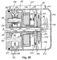
- FIG 28 there is shown a cross sectional view through a joint according to an embodiment of the invention.
- the joint comprises mechanical, electro-mechanical, electronic and optical elements that are mutually interconnected, either directly via electrical connectors or via wireless, for instance optical, coupling to other elements.
- PCB printed circuit board 131
- optical encoders 132, 133 are used and a safety brake 134, 135 is implemented using a very small solenoid 134.
- the brake is designed such that the solenoid 134 can activate and deactivate the brake with a very limited force.
- the encoder 133 used for determining the position (angular orientation of the axle/rotor) of the motor (angular orientation) is mounted at the rear surface of the PCB 131.
- the motor shown in figure 28 comprises a stator part 136 and a rotor part 137.
- the encoder 132 used for determining the angular orientation of the output axle 138 or output flange 139 of the joint is mounted on the front surface of the PCB or in a socket on the front surface of the PCB 131.
- a high resolution encoder is used and the short distance between the hollow axle 138 and the encoder is important in order to attain a proper positioning of sensor and encoder disc relative to each other.
- the encoder disc 140 is mounted on the hollow axle 138 through which electrical and pneumatical connections 141 are guided through the joint and the hollow axle 138 is connected to the output flange 139.
- the safety brake 134, 135, which stops the robot 137 for instance at power drop-out, is formed as an integral part with the PCB 131.
- the solenoid 134 which in the event of power drop-out displaces a ratchet 142 into engagement with an annular member 135 mounted on the motor axle 143, is mounted directly on the PCB 131.
- This annular member 135 (friction ring) can rotate relative to the motor axle, but there is a high friction between the annular member and the motor axle 143. This ensures a controlled halt of the joint but without halting the joint so abruptly that the robot arm becomes overloaded.
- friction between the annular member 135 and the motor axle 143 is ensured by O-rings 144 tightly fitted between the motor axle 143 and the annular member 135 (friction ring).
- the joint according to this embodiment of the invention is designed such that adjacent joints can be attached to each other without use of further elements. Attachment of the joint to an adjacent joint or connecting member (for instance a thin-walled tube) takes place via the output flange 139 and the connecting portion 145 on the housing 146 of the joint.
- robot joints according to the invention can be coupled together by suitable members, for instance thin-walled tubes, which constitutes a preferred choice due to their optimal rigidity/weight ratio.
- the joint according to this embodiment of the invention comprises a seal 147 between the housing 146 and the output flange 139, main bearings 148 resting against inclined inner surface portions (bearing surfaces) 155 provided in the housing 146, sealed bearings 149, transmission 150, at least one passage 151 for connections from an adjacent joint or connecting member, an area/space (152) for a slip ring and for twisting wires 141, when the output members 138, 139 rotate, further bearings 153 and a plate 154, for instance of aluminium or other suitable material, for mounting the PCB 131 and also for acting as a heat sink for power electronics in the joint.
- a single four point of contact ball bearing or a single crossed roller bearing or a pair of angular contact ball bearings could be used.
- eccentric gear arrangement with a single eccentric pinion
- eccentric gear arrangement with 2 pinions, phaseshifted 180 degrees, or 3 pinions, phase shifted 120 degrees
- a harmonic drive gear can be used in the unit, either with or without an integrated output bearing.
Abstract
Description
- The invention relates generally to programmable robot systems and robots and more specifically to user interface means for such robots, joints for such robots, methods for programming of such robots and databases for storing information relating to the programming and operations of the robot system.
- Programmable robots for use in industry are generally known. A traditional method of programming such robots consists of initially guiding the robot, for instance the tool or end effector on the robot arm from an initial point in space, for instance a pick-up location through a desired path in space leading to a final destination of the end effector, where an object initially picked up may be delivered. The robot or external control means are provided with storage means for storing information relating to the above movement from an initial to a final position. After this learning session the robot is able to repeat the procedure and carry out the task to be performed. In stead of moving the end effector of the robot through the desired path as described above a dedicated tracking device for tracking the desired path in space may also be employed, an example of such a system being for instance shown in
US 5,495, 410 . - Generally, the programming of robots used in industry requires specialised knowledge and can only be performed by persons skilled in the art, often referred to as system integrators. In connection with multi-purpose robots for use in industry or even at home, it would be advantageous to have access to a robot with user interface means facilitating quick and simple programming of the robot, including reprogramming from one task to another which can be performed by any person, not only a person with special skills within this art.
- It would furthermore be advantageous to have access to a programmable robot provided with simple means for avoiding hazards to the surroundings such as collisions with surrounding equipment, boundaries or persons.
- It would furthermore be advantageous to have access to a programmable robot provided with means for storing a number of working scenarios, i.e. information on the specific working procedures, initial and final positions of the end effector and trajectories in space of the end effector or other portions of the robot, characteristics of objects to be approached and handled by the robot and information on the surroundings limiting the allowable trajectories of portions of the robot, i.e. a description of the relevant characteristics, boundaries, objects, etc. in the surroundings.
- The above and other objects are according to the present invention attained by a programmable robot system, a control system for such a robot and user interface means for such a robot. The invention furthermore relates to a method for programming the robot using such interface means. The invention furthermore relates to a database for storing information relating to programming and operation of a robot and to a joint for use in a robot.
- It is specifically an object of the present invention to provide a programmable robot system which can be programmed in a simple and easy manner without this requiring specialised knowledge, i.e. which can be performed for instance by an operator or technician in industry or even by a private person for instance at home.
- It is a further object of the invention to provide a programmable robot system which can easily be re-programmed to perform different operations and thereby be used for performing different operations part-time in for instance an industrial setting, thus avoiding the necessity of using a number of dedicated robots which may only be required to operate less than full time.
- It is a further object of the present invention to provide a method for programming a robot.
- It is a further object of the present invention to provide a user interface, which facilitates quick and straightforward programming of a robot.
- These and further objects are according to the invention attained by a robot system comprising
- (a) a robot comprising a number of individual arm sections, where adjacent sections are joined by a joint;
- (b) controllable drive means provided in at least some of said joints;
- (c) a control system for controlling said drive means,
- (d) user interface means either provided externally to the robot, as an integral part of the robot or as a combination hereof;
- (e) storage means for storing information related to the movement and further operations of the robot and optionally for storing information relating to the surroundings.
- According to a specific embodiment of the invention, the robot can be provided with sensor means for sensing the position of various portions (for instance the joints and/or the end effector) of the robot relative to the surroundings.
- According to a specific embodiment of the invention said sensor means comprise one or more cameras, which can for instance be provided in the vicinity of the end effector and which can for instance be applied to identify and recognise objects to be handled by the robot or other relevant objects, boundaries etc. in the surroundings.
- The invention furthermore relates to a robot comprising:
- (a) a robot comprising a number of individual arm sections, where adjacent sections are interconnected by a joint;
- (b) controllable drive means provided in at least some of said joints;
- (c) a control system for controlling said drive means;
- (d) attachment and drive means for a tool;
- A very important aspect of the present invention relates to the user interface. The user interface does thus not primarily address the person skilled in the art of setting up and programming industrial robots but rather anybody employed in an industrial setting or even at home who quickly and yet reliably needs to apply a robot to a specific task or to change the application of a robot from one task to another. According to a specific embodiment of the invention, the robot can be programmed and controlled from a standard personal computer running for instance a Windows program. An example of the programming of a robot according to the invention is given in the detailed description of the invention. Such programming and control may of course also be performed from a dedicated programming/control unit provided with a suitable man/machine interface comprising for instance a computer mouse and/or touch screen or other display screen and/or a keyboard. The PC or programming/control unit may also comprise the storage means described above.
- The user interface according to the invention may alternatively be distributed between an external user-accessible control means provided at appropriate portions of the robot, for instance on the various joints. Thus for instance the joints could be provided with control buttons for moving each individual joint during the initial programming session for instance in order to avoid collisions with objects or boundaries in the surroundings. Such local control members on the appropriate parts of the robot could if desired be supplemented with sensor means for sensing the proximity of for instance the joints or the end effector to objects or boundaries when the robot is actually working. Thus if one or more of said objects or boundaries during a working session of the robot change their positions in space within certain limits, the robot will at least to some extent be able to sense such changes and apply appropriate measures to counteract detrimental effects of such changes.
- By application of the user interface means of the invention, the relevant objects and boundaries in the surroundings may be located using the robot itself, for instance by moving the end effector - or for that matter any other part of the robot - to a number of points characterising the object or boundaries sufficiently. Thus for instance a planar boundary may be defined my moving the end effector to at least three points on the boundary and via the interface means specifying the corresponding space coordinates, whereby a plane boundary will be specified. A curved boundary of course requires a larger number of Cartesian coordinates to be specified, but under certain circumstances (for instance spherical or cylindrical objects or boundaries) other co-ordinate systems my be applied for specifying their extension in space.
- According to a preferred embodiment of the invention, which will be described in detail in the detailed description of the invention, the user interface means comprises a display screen on which a picture of the robot and optionally also relevant portions of the surroundings is shown at least during the programming session of the robot. Thus, the robot could optionally be remotely programmed in cases where access to the work area for some reason is undesired or even impossible, for instance by initially specifying the position of the relevant objects and boundaries of the work. Sequences showing the movement of the robot and the relevant portions of the surroundings corresponding to a number of work areas and operations of the robot may be stored in the storage means and retrieved when the robot changes from one application to another. Thus, in fact a database comprising all relevant working scenarios of for instance an industrial plant may be gradually established, which greatly facilitates application of the robot for various purposes in an industrial setting or even at home.
- It is understood that although the robot itself, its control system and the user interface used to program and/or control the robot in the present specification are described in terms of a single system, each of these entities could be used separately for instance in connection with other entities. Thus, also other controllable robots than the one described by the various embodiments hereof could be programmed and/or controlled using the control system and/or user interface means of the invention.
- The present invention furthermore relates to a method for programming a robot according to the invention, a database for storing information relating to programming and operation of a robot and to a joint for use in a robot according to the invention. It is, however, understood that the method, database and joint according to the invention may also find application either together or separately in connection with other robots.
- The following embodiments are furthermore disclosed:
- 1. A programmable robot system comprising:
- (a) a robot comprising a number of individual arm sections, where adjacent sections are interconnected by a joint;
- (b) controllable drive means provided in at least some of said joints;
- (c) a control system for controlling said drive means,
- (d) user interface means comprising means for programming the robot system, said user interface means being either provided externally to the robot, as an integral part of the robot or as a combination hereof;
- (e) storage means co-operating with said user interface means and said control system for storing information related to the movement and further operations of the robot and optionally for storing information relating to the surroundings.
- 2. An embodiment including the features of
embodiment 1, wherein said control system comprises means for controlling triggering of actions performed by the robot and/or a tool mounted on the robot. - 3. An embodiment including the features of
embodiment 2, wherein said means for triggering comprises external sensor means for placement on portions of the robot and/or on external entities in the surroundings. - 4. A robot comprising:
- (a) a number of individual arm sections (5, 8), where adjacent sections are interconnected by a joint (6);
- (b) controllable drive means provided in at least some of said joints;
- (c) a control system for controlling said drive means;
- (d) attachment and drive means for a tool.
- 5. An embodiment including the features of
embodiment 4, wherein the robot is furthermore provided with sensor means (10) for sensing the position or extent of an object (14) to be manipulated by the robot. - 6. An embodiment including the features of
embodiment - 7. An embodiment including the features of
embodiment 4, comprising at least two joints connected to each other without interconnecting arm sections. - 8. An embodiment including the features of
embodiment 4, wherein the robot comprises six joints defining six axes of rotation (A1, A2, A3, A4, A5, A6). - 9. User interface means for a programmable robot comprising:
- (a) a display screen for showing menus relating to programming steps to be performed by a user during programming of said robot and/or a computer-generated representation, such as a 3 dimensional representation of the robot showing the robot at least during programming of the robot, but optionally also during test run and/or during actual operation of the robot; and
- (b) means for entering instructions to a control system of the programmable robot.
- 10. An embodiment including the features of
embodiment 9, wherein it furthermore comprises storage means, either in the interface means or operatively connected to the interface means for storing information relating to programming and operations of the robot and optionally also for storing information relating to the surroundings of the robot, such as obstacles to be avoided during movement of the robot and/or prohibited regions in space. - 11. An embodiment including the features of
embodiment 9, wherein the interface comprise software applications containing one or more wizards that can be chosen by a user for aid during programming of the robot. - 12. An embodiment including the features of
embodiment - 13. An embodiment including the features of
embodiment - (a) an external programming and control unit provided with a display screen for displaying menus and/or computer-generated pictures of the robot at least during programming and initial control/supervision of the robot and means for entering directions and information to the control system of the robot; and
- (b) external sensor and/or entry means for placement on chosen portions of the robot or remote from said programming and control unit or for tracing paths in space which will be followed by portions of the robot during programming and operation of the robot.
- 14. An embodiment including the features of any of the preceding
embodiments 9 to 13, wherein computer-generated images of pertinent parts of the surroundings can furthermore be displayed on the display screen. - 15. An embodiment including the features of
embodiment 13, wherein said external sensor and/or entry means comprises a 3D-mouse ("space mouse") or a joystick. - 16. A method for programming a robot comprising specifying a path of movement in space of either the tool of the robot or one or more joints of the robot by defining a plurality of waypoints (Xi, Yi, Zi) through which the tool or one or more joints of the robot shall pass during performance of a given task.
- 17. An embodiment including the features of
embodiment 16, wherein the method furthermore comprises specification of the position and/or spatial extent of obstacles and/or prohibited regions in the surroundings of the robot, with which obstacles parts of the robot must not collide during operation and/or through which prohibited regions parts of the robot must not pass during operation of the robot, said obstacles and prohibited regions forming scenarios corresponding to specific operational conditions and surroundings of the robot. - 18. An embodiment including the features of
embodiment - 19. An embodiment including the features of
embodiment - 20. An embodiment including the features of any of the preceding
embodiments 16 to 19, wherein said specification is accomplished using signals from one or more encoders provided in the joints of the robot. - 21. An embodiment including the features of any of the preceding
embodiments 16 to 20, wherein said specification is accomplished using signals from one or more external sensors provided on the robot. - 22. A method for programming a robot comprising user control of the position and movement of the robot tool in space by means of a user interface comprising control means for controlling said position and movement of the tool and by means of said user interface indicating the position and/or orientation of the tool at a number of positions in space and storing said position and/or orientation in storage means in a control system of the robot, where at least one of said positions of the tool is in the vicinity of an object to be handled by the tool.
- 23. An embodiment including the features of any of the preceding
embodiments 16 to 22, comprising user control of the position and movement of the robot tool in space by means of a user interface comprising control means for controlling said position and movement of the tool and by means of said user interface indicate the position and/or orientation of the tool at a number of positions in space and storing said position and/or orientation in storage means in a control system of the robot, where at least one of said positions of the tool is in the vicinity of an object to be handled by the tool, and where the method furthermore comprises the sensing or identification of said object at said at least one position of the tool. - 24. An embodiment including the features of
embodiment 23, wherein said sensing or identification of the object takes place by recording an image of the object. - 25. An embodiment including the features of
embodiment 24, wherein said recorded image of the object is subjected to image processing in order to identify and distinguish it from the surroundings and that the processed image is used to provide parameters to the control unit of the robot relating to the particular object to be handled by the robot. - 26. A database comprising programming and control information relating to a programmable robot, said database for at least one operation of the robot comprising information specifying initial position of a tool, activation/triggering parameters of the tool at the initial position, final position of a tool, activation/triggering parameters of the tool at the final position and information relating to the path in space followed between initial and final position and vice versa.
- 27. An embodiment including the features of
embodiment 26, wherein said database furthermore comprises at least one scenario including information about relevant portions of the surrounding of the robot in specific operational situations, such as prohibited areas, position/spatial extent of pick-up areas and placement areas, position and spatial extent of obstacles with which portions of the robot may collide during operation, information relating to triggering of events, etc. - 28. An embodiment including the features of
embodiment - 29. A joint for a robot comprising a safety brake comprising a solenoid (134) which upon activation of the brake displaces a ratchet (142) into engagement with an annular member (friction ring) (135) mounted on the motor axle (143), where the annular member (135) can rotate relative to the motor axle (143), but with friction between the annular member (135) and the motor axle (143).
- 30. An embodiment including the features of
embodiment 29, wherein said solenoid is mounted on a printed circuit board (PCB) (131) that is fixed relative to the housing (146) of the joint. - 31. An embodiment including the features of
embodiment 29 or 30, wherein it comprises encoder means (132) for sensing the angular orientation of an output axle (138) or output flange (139) and encoder means (133) for sensing the angular orientation (rotation) of the motor (136, 137). - 32. An embodiment including the features of
embodiment - 33. An embodiment including the features of
embodiment 32, wherein said connecting portion (145) is provided substantially at 90 degrees relative to said output axle (138) and/or output flange (139). - 34. An embodiment including the features of any of the preceding
embodiments 29 to 33, wherein the housing (146) is provided with a space (152) for accommodating wires (141) or other connecting means. - 35. An embodiment including the features of any of the preceding
embodiments 29 to 34, comprising bearings (148) resting against inner surface portions (155) or bearing surfaces or bushes (28', 28", 29', 29") provided in the housing (146) that are inclined relative to the longitudinal axis X through the housing. - The invention will be better understood with reference to the following detailed description of embodiments hereof in conjunction with the figures, where
-
Figure 1 shows a schematic perspective view of an embodiment of the robot according to the invention, set up to perform a simple pick-and-place operation, the view furthermore comprising definitions of Cartesian and spherical coordinates for characterising positions and orientations of various components of the robot; -
Figure 2 shows a schematic perspective view of a second embodiment of the robot according to the invention comprising three joints; -
Figure 3 shows a schematic perspective view of a third embodiment of the robot according to the invention comprising four joints; -
Figure 4 shows a schematic perspective view of a fourth embodiment of a robot according to the invention (a so-called "Scara-robot"); -
Figure 5 shows a schematic cross sectional side view of a joint with the main components housed in the joint; -
Figure 6 shows a schematic cross sectional side view of two adjacent joints and the bearings used in these joints. -
Figure 7 shows a schematic view of an opening page shown on a display screen on a user interface/user control unit used to programme and control the robot, where the opening page basically comprises two portions, a menu portion where a user can enter instructions to the programming/control system of the robot and an image of the actual physical robot following the movements of the actual robot; -
Figures 8 to 10 show a sequence of display screen images displayed to a user on the user interface during an initial sequence of steps to be performed by the user during a programming session of the robot; -
Figures 11(a) and(b) show a schematic view of a specific embodiment of the menu portion of the screen page used for programming the position and orientation of the tool at the various waypoints along the path of the tool in space from an initial position to a final position and back to the initial position; -
Figures 12 to 14 show schematic representations of screen pages presented to the user during the remaining programming steps of the robot; -
Figures 15 to 23 show a sequence of CAD images of a robot according to an embodiment of the invention displayed on the display screen of the user interface during the various stages of an operation of the robot, the robot during programming being either controlled from the user interface as described infigures 6 to 13 or being actually gripped by the user and guided through the waypoints along the path in space; -
Figure 24 shows a further embodiment of a screen image of a user interface according to the invention; -
Figure 25 shows a still further embodiment of a screen image of a user interface according to the invention; -
Figure 26 shows a first embodiment of a six-axis robot according to the invention; -
Figure 27 shows a second embodiment of a six-axis robot according to the invention; and -
Figure 28 shows a cross sectional view through a robot joint according to an embodiment of the invention. - As mentioned, the present invention relates to a programmable robot system, i.e. both to the robot itself, to the control system used for controlling the movements and functions of the robot including its end effector and storage means for storing pre-programmed movements and functions and relevant information about the objects to be handled by the robot and about the surrounding, in which the robot is working. The invention furthermore relates to a user interface used for communicating and controlling the robot at least during programming of the robot and furthermore for retrieving pre-programmed scenarios and patterns of movements etc. of the robot so that it can be used to perform different tasks for instance in an industrial setting without it being necessary to re-programme the robot for each new task.
- In the following there are shown various embodiments of the robot itself and of the programming facilities (user interface) used to programme and control the robot but it is understood that a person skilled in the art may design modifications and variations to the embodiments actually shown without such modifications and variations falling outside the scope of the invention as defined by the appended claims.
- According to an embodiment of the robot system according to the invention, the robot is at least able to perform the following operations (functionalities): (a) a pick-and-place operation, (b) a filling operation, and (c) a palletising operation. These operations or functionalities are implemented using a number of basic, primitive functionalities:
-
- Fixed position: The robot/the tool itself is either drawn or controlled from a user interface/control unit to the desired position and the approach vector is defined by the direction to the tool.
- Pallet: A plurality or an array of positions is specified as under "fixed position", but optionally corners, number of rows and columns or a pattern of positions could be specified.
- Time-controlled position: According to this option, a fixed position which an object is predicted to have reached a given interval of time after the activation of a trigger is determined.
- Distance-controlled position: According to this option, a fixed position which an object is predicted to have reached after moving a certain distance after the activation of a trigger is determined. This functionality requires that the velocity of the object be known (for instance the velocity of a conveyor upon which the object is placed).
- Variable time-controlled position: According to this option, an initial and a final position are determined by means of time-controlled position. The exact position of the object between these two positions can be determined on-line based on time.
- Variable distance-controlled position: According to this option, an initial and a final position are determined by means of distance-controlled position. The exact position of the object between these positions can be determined on-line if the velocity of the object is known.
-
- Time-controlled tracking: According to this option, an initial and final position is specified by means of time-controlled position. The object is tracked between these two positions based on time.
- Distance-controlled tracking: According to this option, an initial and a final position are specified by means of distance-controlled position. The object is tracked between these two positions based on the velocity of the object (for instance measured by the velocity of a conveyor upon which the object is placed).
-
- Intermediate positions or waypoints (of the tool) are defined by the above-mentioned methods and a path in space is adapted to these intermediate positions or waypoints.
- A sequence of positions (of the tool) is recorded and stored (dependent on the possibility of actually leading the robot (the tool mounted on the robot or an arm or joint of the robot) through a path in space without too much resistance from the robot).
-
- Distance-measuring means ("trip control") for instance on a conveyor belt.
- Time
- Sensor means, for instance light switch means, cameras, magnetic sensors, etc.
- Gripper sensor means.
-
- Tool approaching the object (via approach vector)
- Tool moves away from the object
- Activate the tool (gripper, sucking disc, paint pistol, etc.)
- De-activate the tool (gripper, sucking disc, paint pistol, etc.)
- Typical sequences of actions performed by the robot during the above three basic operations will comprise:
A typical pick-and-place operation: (a) Pattern of movement: Move to fixed initial position (b) Trigger: Light switch (c) Pattern of movement: Move to distance-controlled position (d) Action: Approach object (e) Action: Activate tool (f) Action: Move away from object (g) Pattern of movement: Through waypoints to fixed position (h) Action: De-activate tool (i) Pattern of movement: Through waypoints to fixed initial position A typical pattern of movement operation: (a) Pattern of movement: Move to fixed initial position (b) Trigger: Light switch (c) Pattern of movement: Move to distance-controlled position (d) Tracking: Distance-controlled tracking (e) Action: Activate tool (f) Trigger: Time (g) Action: De-activate tool (j) Pattern of movement: Through waypoints to fixed initial position A typical loading operation: (a) Pattern of movement: Move to fixed initial position (b) Trigger: Light switch (c) Pattern of movement: Position sequence with timing (d) Pattern of movement: Through waypoints to fixed initial position - The user interface according to the invention comprises wizards, i.e. simple sequences of screen images or menus by means of which the user can specify the standard operations to be performed by the robot. A wizard for the pick-and-place operation will comprise a sequence of screen images corresponding to the sequence of functions of primitive functionalities described above. Exemplary embodiments of such wizards will be described in the following.
- Referring to
figure 1 , there is shown a schematic perspective view of an embodiment of the robot according to the invention, set up to perform a simple pick-and-place operation, the view furthermore comprising definitions of Cartesian and spherical coordinates for characterising positions and orientations of various components of the robot. Definitions of coordinates in relation to the base and joints of the robot are given infigure 1(a) and definitions of the position and orientation of the tool are given infigure 1(b) . - In
figure 1(a) , the shown embodiment of a robot according to the invention is generally designated byreference numeral 1 and consists of abase arm sections base wrist section tool 12, respectively, which as an example may consist of agripper 12 schematically shown infigures 1(a) and (b) . Between thebase 2 and thefirst arm section 5 are provided first interconnecting means comprising thesections 3 and 3'. The first interconnecting means are mounted for rotation about the longitudinal axis Z through thebase first arm section longitudinal axis 16 through the interconnecting means 3, 3' as indicated by the angle β. Thefirst arm section second arm section joints 6, 6', about thelongitudinal axis 17 of which thesecond arm section section wrist section tool 12. This section comprises three mutually perpendicularlongitudinal axes - For the six-joint embodiment described above, the orientation of each joint can be specified by the rotational angle about the corresponding axis of rotation, i.e. the angles α, β, γ, δ, ε, µ in the figure. Alternatively, the position (for instance the X, Y, Z co-ordinates of the tool: (Xt, Yt, Zt)) and the orientation of the tool for instance defined by the co-ordinates: roll, pitch, yaw can be specified. These co-ordinates are defined in
figure 1(b) . Specifically the co-ordinate roll denotes a rotation around the longitudinal axis y' of the tool, pitch denotes a rotation around the lateral axis x' through the tool and yaw denotes a rotation around the vertical axis z' through the tool. The control system can determine the required set of angular orientations (rotational angles α, β, γ, δ, ε, µ) of the joints from the position/orientation (X, Y, Z, roll, pitch, yaw) of the tool and vice versa. - Finally,
figure 1(a) shows schematically the robot set-up for use in a pick-and-place operation, where an object 14 (for instance a piece of chocolate) is placed on aconveyor 13 for pick up and placement in abox 15 placed adjacent the conveyor. During this process, the tool of the robot travels from an initial pick-up position or waypoint w1 through a number of chosen waypoints w2, w3 to its final placement destination w4. According to the invention, the number and position in space of these waypoints can be specified during the programming session of the robot as will be described in detail below. - In connection with
figure 1 , a specific embodiment of the robot according to the invention has been shown, but the robot according to the invention may be constructed in a number of different ways, for instance comprising different numbers of joints. Three such alternative embodiments are shown infigures 2 ,3 and4 . Specificallyfigure 2 shows a schematic perspective view of a second embodiment of the robot according to the invention comprising three joint, andfigure 3 shows a schematic perspective view of a third embodiment of the robot according to the invention comprising four joints.Figure 4 finally shows a schematic perspective view of a fourth embodiment of a robot according to the invention (a so-called "Scara-robot"). The embodiment shown infigure 1 makes it in principle possible for the tool to attain any position and orientation in space, but in cases where more restricted movements of the robot and more restricted positions and orientations of the tool are required, less complicated embodiments as for instance shown infigures 2 ,3 and4 may be applied. - Referring to
figure 5 there is shown a schematic cross sectional side view of an interconnecting means or joint according to an embodiment of the invention comprising the main components: atransmission 22, amotor 23 and encoding and controlling means 24. The latter comprises an encoder for registering the rotational angle α, β, γ, δ, ε, µ of the particular joint. The encoder could consist of an optical encoder (relative/incremental or absolute) for instance comprising adisc 26 mounted for rotation with themotor 23 and provided with a pattern of through openings through which a light beam from a light source placed in ahousing 27 may penetrate. Encoders of this kind are known for a variety of purposes. Themotor drive axle 25 running longitudinally in the interconnecting means is hollow in order to allow for the passage of electrical leads, not shown, between the various portions of the robot. - Referring to
figure 6 there is shown a schematic cross sectional side view of two adjacent interconnecting means (joints) for instance in the wrist section of the robot and thebearings bushes 28', 28", 29', 29" inclined relative to the longitudinal axis X through the joint. These bearings are advantageous because a clearance or wobble-free bearing arrangement can be obtained by means of two simple and inexpensive ball or roller bearings in stead of using so-called "crossed roller bearings", which are much more expensive, but which can be made clearance or wobble free and take up tilt and forces in all directions. - By using joints according to the invention as for instance shown in
figures 5 and6 , it is possible to provide a modular robot, which can be designed (for instance with respect to the number of joints) according to individual applications. - A very important aspect of the present invention is to provide a user interface facilitating the programming and control of the robot according to the invention to such a degree that virtually any person may be able to use the robot. The following paragraphs describe various embodiments of such programming and control user interface means.
- Referring to
figure 7 there is shown an opening page of a programming/control software application according to the present invention to be displayed on a user interface. The user interface may as mentioned be provided as a dedicated external unit, a kind of "remote control" of the robot or it may be implemented on a personal computer. It is, however, also possible to distribute the interface means, whereby a part of these, for instance display screen and information storage means for storing chosen parameter combinations, and descriptions of the surroundings are provided in an external unit, whereas guide and sensor means for actually guiding the robot through the path in space, which it must follow for performing the required task and for recording the positions of the tool and joints in space, are provided as separate units, which might be placed at appropriate places on the robot programming. Such separate means may also be used for determining the position and special extent of elements/obstacles and boundaries in the surroundings. The opening page shown infigure 1 comprises basically a menu section (a) and a picture section (b), and in this example is shown a schematic perspective view of an other embodiment of a robot according to the present invention somewhat differing from those described above. Although the following sequence of screen images shown infigures 8 to 14 show only the menu portion (a), preferably these images shown on the display screen of the programming and control unit during programming and/or control sessions will comprise both the menu portion shown infigure 1 under (a) and a CAD presentation of an appropriate robot as shown under (b) infigure 1 with the CAD image of the robot shown corresponding to the parameter choice of the corresponding menu portion. In other words, the CAD image moves with the changes of parameter settings performed by means of the menu portion. Also as mentioned the image of the robot (b) may comprise graphical representations of relevant objects, boundaries etc. in the surroundings. - The robot according to the shown embodiment of the invention is generally designated by
reference numeral 1 and comprises abase 2,joints arm sections end effector 6 in the shown embodiment in form of a gripper. Optionally one ormore vision cameras 10 may be provided on the robot, in the shown embodiment in the vicinity of the end effector. - The menu portion (a) generally designated by
reference numeral 11 contains the opening page of the control software application of the invention and provides the user with a choice between the creation of a new program, 12, the retrieval of a preloaded program, 13, a test and calibration procedure, 14 and the execution of the program, 15. - Assuming the user selects "Create new program", 12, the menu portion shown in
figure 8 appears (preferably together with the CAD picture of the robot as mentioned, although this picture is omitted from the following figures). -
Figure 8 shows the "Create new program"menu 16 chosen by the user. In this menu, the user may choose between different operations to be performed by the robot. In the example shown infigure 8 , these operations comprise a "pick-and-place"operation 17, a "bottle filling operation" 18, a "repeated motion"operation 19, a "stacking"operation 20 and anempty program 21, which may be specified by the user. - Assuming the user selects "pick and place", the menu portion shown in
figure 9 appears on the display screen of the programming and control unit. - The pick-and-place operation comprises four actions to be performed by the robot indicated by 23, 24, 25 and 26 on
figure 9 , and these may be activated for instance by a computer mouse or by a touch in the corresponding icon in case of a touch screen. Specifically 23 indicates a pick operation, 24 indicates the movement to the destination via a sequence of waypoints to be described below, 25 indicates the place operation performed by the end effector at the destination point and 26 indicates the movement of the end effector back to the initial position. Using the menu shown infigure 8 and the subsequent figures, the whole pick-and-place operation can de defined and stored for subsequent automatic execution by the robot. - Assuming the user chooses to define the pick operation, the
icon 23 is activated and themenu portion 31 shown infigure 10(a) will appear. By pressing theposition icon 35, the position/orientation assumed by different portions of the robot can be specified. Thus, by pressing icon 32 (tool position), the position of the tool in space at the pick-up point can be specified and by pressing icon 33 (tool orientation), the orientation of the tool at this point can be specified. The angular orientation (α, β, ...) of each of the robot joints can be specified if desired by pressing icon 34 (joints). In the example shown infigure 10(a) , thejoint icon 34 has been pressed resulting in the angular orientation adjustment means indicated byreference numerals trigger icon 36 as described below in connection withfigure 12 . - An alternative screen picture 31' corresponding to the one shown in
figure 10(a) is shown infigure 10(b) , where a CAD-generatedpicture 101 of the robot is shown in thepicture field 31". By application of theicons slice control icon 105, whereby either a coarse or fine adjustment of the robot will be possible. - Defining the position of the tool in space requires the specification of three co-ordinates. If accomplished from the user interface, this can be done in a number of ways. One possibility would be to apply means on the display screen corresponding to those shown in
figure 10(a) or(b) for adjustment of the angular orientation of the joints, i.e. the screen picture could contain three of the adjustment means shown infigure 10(a) or(b) , one of these for specifying the X co-ordinate, one for the Y co-ordinate and one for the Z co-ordinate of the tool. Alternatively, the co-ordinates could be entered from a keyboard. As a further alternative, a screen picture as shown schematically infigure 11(a) could be used. It is understood that in stead of specifying the position of the tool by its Cartesian co-ordinates, other co-ordinate systems (spherical, cylindrical etc.) might be applied if desired. When the control means specifying the position of the tool are manipulated, the picture of the robot 43 moves correspondingly. - Referring to
figure 11(a) there is thus shown ascreen page 106 for specifying the position of the tool. According to this embodiment, the X, Y, Z co-ordinates of the tool can be controlled by the corresponding arrow-shapedicons figure 11(a) . The speed of adjustment can be set by means of theslide control icon 96. Theicons icons - Referring to
figure 11(b) there is shown ascreen page 110 for specifying the orientation of the tool by setting the co-ordinates: roll, pitch and yaw by means ofarrow icons icons - As a further alternative for specifying the position of the tool (and its orientation and in fact all movements of the robot), a joystick or a 3D-mouse might be used. A 3D-mouse could according to the invention be used for other programming and control purposes as well. For instance a 3D-mouse could be used to record the position and spatial extent of objects and boundaries in the surroundings, such as obstacles to be avoided by the robot and boundaries of the work area at the application site. As mentioned, this information might be stored in storage means connected to the control system for later retrieval and application.
- Referring to
figure 12 there is shown themenu portion 45 which will appear on the display screen of the user interface if icon 36 (trigger) is pressed on the menu portion shown infigure 10(a) . Using themenu portion 45, various parameters defining the triggering of the tool during the pick-up operation can be specified. Four such trigger parameters are indicated byreference numerals Reference numeral 47 indicates activation of the tool after the object has travelled a certain distance, which can be specified on themenu portion 45, and which in the example shown amounts to 10 cm after a trigger event, for instance the passage of the object through a light switch. Alternatively as indicated byreference numeral 48, the tool may be activated after the object has travelled for a given interval of time after the trigger event, where the interval can be specified on themenu portion 45 and which in the example shown amounts to 0.01 seconds. As a further alternative, the tool may be provided by sensor means providing a signal to the control system of the robot, thereby activating the tool. This option is indicated byreference numeral 49 infigure 12 . It is possible to choose between different sensors and/or sensor locations as indicated byreference numeral 50. - The next step in the programming procedure is shown in
figure 13 and consists of specifying a suitable number of waypoints through which the tool of the robot shall move from an initial position to a final position and back to the initial position. Themenu portion 51 corresponding to this step is shown infigure 13 . The path in space from initial to final position of the tool can be the same as the path followed by the tool on returning from the final to the initial position but different paths may also be chosen and specified if appropriate. After pressingicon 52, the waypoints can be specified by their co-ordinates in space, for instance in the same manner as shown and described previously in connection withfigure 10 . Alternatively, a 3D-mouse or similar device may be positioned at the different waypoints and the corresponding co-ordinates be entered into the control system of the robot directly from the mouse. In fact, it could be possible to trace the whole continuous path in space of the tool and store this in the control system in stead of storing a number of distinct points in space. In principle it may be possible under circumstances not to specify any waypoints at all, but usually at least waypoint between the initial and final position of the tool will be required. The chosen number is indicated on themenu portion 51 at 53, and waypoints can be removed or added at 54 and 55. - Referring to
figure 14 , the two remaining programming steps of a pick-and-place operation is described, i.e. the specification of the position and triggering of the place operation of the tool at the final position and the return of the tool to the initial position. The specification of these steps corresponds to the specification of the initial position and triggering of the tool and the movement of the tool through a chosen number of waypoints from the initial to the final position of the tool and will hence only be described briefly in the following. On theprogram portion 60 of the page, the previously chosen position and triggering of the tool during pick up and movement from initial to final position can be retrieved fromicons icons 57 and the return path from final back to initial position can be specified aticon 58. - After the specification of all pertinent parameters relating to the pick-and-place operation, the program is ready for execution. Starting the program from
icon 59 will result in both the physical robot and its picture (CAD representation) on the screen carrying out the programmed operations slowly in order to ascertain the correct and unimpeded operation of the robot. After this control step, the robot is ready for normal operation. - An alternative embodiment of a program "wizard" used for programming the robot according to the invention will be briefly shown and described by reference to
figures 15 to 23 . These figures show a sequence of CAD images of a robot according to an embodiment of the invention displayed on the display screen of the user interface during the various programming stages of the robot. The actual movement of the robot - and hence its CAD-generated image on the interface screen - will in this case take place by actually leading the physical robot through the various steps performed during programming of the robot. Alternatively, the robot might be controlled in a manner corresponding to that described previously in connection withfigures 7 to 14 . In conjunction with the description of this sequence of movements of the robot means and procedures for controlling the pick up of an object by the tool of the robot will be described specifically in connection withfigure 18 . - Referring to
figure 15 there is thus shown a screen image of anopening page 61 of the programming wizard according to this embodiment of the user interface of the present invention. Specifically the page comprises amenu portion 62 and an image (CAD representation) of arobot 63 according to one embodiment of the invention. Therobot 63 is provided with agripper tool 64 and twocameras 65 used (among other things) for specifying the object to be gripped and handled by the robot. The following series of figures again relate to a pick-and-place operation, but it is understood that numerous other operations could also be programmed using this embodiment of a wizard according to the invention. The kind of operation is specified on themenu portion 62, in the shown example comprising two operations: (1) place and (2) pick and place. The latter is chosen as mentioned. - Referring to
figure 16 there is shown thepage 66 presented to the user during the programming operation. At 67 the user specifies whether the object is to be picked up based on position, colour or sensor activated position. The colour option is chosen as indicated by the arrow. - Referring to
figure 17 there is shown thenext page 68 shown during the programming operation comprising the user indication of theregion 70 within which objects are to be picked up. As explained at 69, thisregion 70 is specified by actually leading the tool of the robot along the entire boundary of the region. Alternatively it might be sufficient to define theregion 70 by a limited number of distinct points, for instance the corners c1, c2, c3 and c4 of theregion 70. This might suffice in case of pick-up regions of simple geometry. The Danish text at 69 actually reads in translation: "Now pull the robot along the edge of the region in which it must look for objects, which it can pick up. [Continue>]". - Referring to
figure 18 there is shown thenext page 71 used in a first step in an object identification method according to the invention. As indicated at 72 (in translation: "pull the robot to a height, where the whole pick-up region can be seen in the picture. [Continue>]") the tool of the robot is elevated above the defined pick-upregion 70 to such an elevation that the whole pick-up region can be seen on thepicture 73 recorded by means of at least one of thecameras 65 placed adjacent thetool 64, a portion of which can be seen in thepicture 73 together with the picture 74' of theobject 74. - Referring to
figure 19 there is shown thenext page 75 presented to the user and comprising the next step of the object identification or segmentation method according to this embodiment of the invention. The text at 76 reads in translation: "Choose a segmentation method that results in the whole object - and only the object - being coloured blue. [Continue>]". Different such methods could be applied but a specific method ("Method 2") is chosen as indicated by the arrow in thefield 77 onpage 75. Thepage 75 furthermore comprises thepicture 73 recorded by the at least onecamera 65 with the picture of theobject 74 as recorded by the camera. Furthermore, a second picture field 78 ("Segmented picture") is shown onpage 75 containing asegmented version 79 of the object. Segmentation methods used in the invention could be based on blob-detection algorithms known from various image processing applications, according to which "blobs" in an image, i.e. areas whose luminosity is above or below a particular value, for instance the value of the adjacent portions of the image, are identified. A segmented picture of theobject 74, i.e. a picture of the object after image processing can be shown on thesecond picture field 78, infigure 19 indicated byreference numeral 79. According to the invention, segmentation can take place by clicking on a point (pixel) on the unprocessed image 74' of theobject 74, i.e. the object which must be recognised by the robot system or alternatively on the surroundingportions 81 of thepicture 73. The object could for instance be a brown piece of chocolate and the surroundings a conveyor belt of a different colour. Clicking on the picture 74' of theobject 74 results in the display of a processedversion 79 of the object. If the user decides that the processing has not been able to identify (distinguish the object sufficiently well from the surroundings), the user may click on another point (pixel) of theunprocessed picture 74 of the object and thereby attain a more satisfactory segmentation of the object. Various other parameters of the segmentation process may also be adjusted from the user interface. After successful segmentation, the algorithm running the image processing can store information relating to the shape of the picture of the object and use this information for later recognition of objects by the robot control system. - Referring to
figure 20 there is shown thepage 82 corresponding to the next step in the programming operation, i.e. the step of specifying the movement of the tool in space from the initial pick-up point (I) to the final (placement) point (II). As indicated by reference numeral 83 (in translation: "Now pull the robot from the pick-up area to the place area. [Continue>]", the user is now instructed to lead the physical robot (tool) through the desiredpath 84 in space and this path can either be recorded and stored in its entirety in the control system of the robot or a number of specific waypoints along the path can alternatively be recorded and stored. - Referring to
figure 21 there is shown thepage 85 corresponding to the placement operation in the pick-and-place operation. As indicated by reference numeral 86 (in translation: "Must the object be placed based on: Position; Colour; Sensor activated position", the user is asked to indicate whether the objects are to be placed based on position, colour or a sensor-activated position. In the example shown, the position option is chosen as indicated by the arrow. - Referring to
figure 22 there is shown thepage 87 used for user specification of thepositions 89, at which objects are to be placed during the placement operation. As indicated by reference numeral 88 (in translation: "Pull the robot around to those positions where it must place objects" [Continue>]), the user is instructed to lead the robot (tool) to thosepositions 89, where objects are to be placed. At each of these positions, the co-ordinates of the position are loaded into the control system of the robot. Alternative procedures for indicating the placement positions to the control system of the robot could also be used. Thus, for instance the "pallet" option mentioned previously according to which corners, number of rows and columns or a pattern of positions are specified could be used as an alternative. - Referring to
figure 23 there is shown thelast page 90 of the programming wizard according to this embodiment of the invention. As indicated by reference numeral 91 (in translation: "Task definition completed. Press continue in order to carry out slow test of the program. [Continue>]), the programming of the robot is finished and a slow control and supervision operation of the robot can be performed by pressingicon 92 onpage 90. - According to the invention programming of the robot is facilitated by a number of features of the user interface and/or control system of the robot. Thus according to a specific embodiment of the invention, the user interface comprises 3D graphical display means for showing a graphical 3D representation of the robot and optionally also its surroundings. The 3D representation of the robot moves during programming and optionally also during actual operation of the robot on the display, which greatly facilitates programming of the robot, also taking the risk of collision of robot parts with the surroundings into account. Furthermore, programming of the robot is greatly facilitated by the use of wizards as already described and these wizards can according to the invention comprise stored templates corresponding to specific operations, which templates can be pre-programmed in the control system or user interface of the robot. Thus, a person skilled in the art of robot programming can create and store templates in the robot system or interface according to the invention with the effect that a user, lacking routine in robot programming, can program the robot to carry out even quite complicated tasks, without the user being forced to make more choices during programming of the robot than absolutely necessary. This makes programming quicker and easier and shortens the time needed for an inexperienced user to familiarise himself with and actually carry out the programming of the robot.
- At any step during programming (and optionally during a subsequent show test run of the program on the robot and/or during actual operation of the robot), the user has a choice between a 3D representation of the robot on the display of the user interface (to give an overview of the operation of the robot) and the display of actual parameter values, co-ordinates etc. at a given instance of the operation. As mentioned, a 3D representation may also comprise the surroundings of the robot. The ability according to the invention to shift between 3D representations of the robot and surroundings and sets of actual parameter values, co-ordinates, etc. greatly facilitates programming and optimisation of the movement of the robot, which - possibly together with the above-mentioned pre-programmed templates - makes programming and operation of the robot according to the invention very easy even for an inexperienced person.
- As mentioned, the robot itself may also by use of the above mentioned encoding and controlling means 24 in the joints of the robot and/or additional sensors provided on the robot be used for programming the robot, i.e. for specifying the path of movement in space of the tool mounted on the robot and/or other parts of the robot, without the necessity to calibrate the system, as the robot uses the same sensors, encoders, etc. to indicate the position, the user wishes to define and to actually bring the robot to the desired position. Using the robot itself (via the sensors, encoders, etc.), also objects in the surroundings, such as objects to be picked up or obstacles to be avoided, can be specified with the robot. For a person not familiar with robot control via an interface this may be an intuitively preferred way of programming the robot. The execution of the program attained and stored in this manner may afterwards be monitored on the display on the user interface and modified if required. Thus, a first, rough programming of the robot can be performed using the robot itself followed by a finer, detailed adjustment of the programming, which may result in a faster and even more optimal programming of the robot, in particular when programming is performed by an inexperienced user.
- Referring to
figure 24 there is shown a further embodiment of a screen image of a user interface according to the invention. The image shows both a 3Dgraphical representation 111 of arobot 112 according to an embodiment of the invention and a list of program steps 113 corresponding to a virtual or actual operation (movement through waypoints and actions to be performed at different steps during the execution of the program) of the robot. On the 3D representation there is shown the path ofmovement 114 of the outermost portion/tool 116 of therobot 112 through a sequence of waypoints 115 (a total of seven waypoints are mentioned in the list of program steps 113, one of these being hidden behind the robot in the graphical representation). The step "action" in the list ofsteps 113 triggers a specific action of the tool that is carried out when the tool arrives at a specific waypoint (for instance that a voltage is applied to one of the digital output channels of the robot system, which causes the activation of a spray nozzle on the tool, spraying for instance paint on an object. In this manner it is possible to indicate the point on the path ofmovement 114 at which spraying is to begin). The shadow image 117 of the robot corresponds to the waypoint indicated by 118 infigure 24 . The shadow image of the robot indicates the virtual movement of the robot and the virtual position of the robot at the different waypoints, thereby giving the user an indication of how the different parts (joints, arm sections and tool) of the real robot will be located in real space, when the tool is positioned in a specific waypoint. If, for instance, a 3D graphical representation of obstacles or prohibited regions in the surroundings of the robot is also incorporated on the screen image, a user may for instance decide whether there is a risk of collision of portions of the robot with objects in the surroundings and whether modifications of the path of movement of different portions of the robot may be required in order to ascertain that no collisions occur during real operation of the robot. - Referring to
figure 25 there is shown another screen image on the user interface according to the invention comprising a3D representation 119 of the robot, afield 120 specifying movements of the tool (different movements of the tool being accomplished by pressing theicons figure 11(a) above). According to the shown embodiment, the manipulations of the tool by means oficons 121 to 125 take place in relation to the same point of view as the 3D representation indicated byreference numeral 119 infigure 25 . - Furthermore, the screen image comprises a field 122 ("Move joints"), by means of which the user may move (rotate) each specific joint separately instead of moving the tool (field 120), where movement of the tool normally results in more than one joint moving (rotating) simultaneously. Using the "Move joints" facility can be useful for instance in those cases, where it is apparent for the user that the desired position of the tool can be attained by simply controlling a single joint. The
numerical values 126 could indicate the relative rotation of each specific joint or the relative rotation of the base joint (in radians or degrees), but other indications could be used and are at any rate not of prime importance for an average used. The indications may be omitted altogether, if desired. The position of the tool in XYZ-coordinates is indicated at 127. Icons referred to by 128, 129 and 130 enable a choice of different configuration spaces. In practice the robot can arrive at one and the same position and orientation (pose) of the tool in a number of different manners. The robot according to this embodiment of the invention have eight different manners in which a given pose of the toll can be attained. Thus for instance the elbow portion of the robot may face either upwards or downwards. The shoulder portion may also be turned 180 degrees and the wrist may also be turned such that the "hand" faces the base of the robot. - With reference to
figures 26 and27 there are shown two embodiments of a six-axis robot according to the invention. The cinematic construction of this robot is chosen such that the following characteristics are obtained: - (1) The construction of each joint is as simple as possible.
- (2) The robot comprises a minimum of different types of joints.
- (3) The members connecting each joints are light-weight, rigid and as inexpensive as possible.
- (4) The design of the robot ensures a ration between the payload and the weight of the robot itself of at least 1/3.
- In order to make each robot joints as simple as possible, each joint has only one degree of freedom - rotation about an axis through the joint - and the connections of the joint with the connecting members are provided at an angle of 90 degrees relative to each other.
- Referring to
figure 26 there is shown a first embodiment of a six-axis robot according to the invention having the above characteristics. The robot comprises the axes A1 through A6. This robot has the cinematic structure: Roll-Pitch-Pitch-Pitch-Roll-Yaw and comprises only two types of joints, three of each type, two types of connecting members in the form of tubes with thin walls, one angle member and one foot member. - With reference to
figure 27 there is shown a second embodiment of a six-axis robot according to the invention having the above characteristics. The robot comprises the axes A1 through A6. This robot has the following cinematic structure: Roll-Pitch-Pitch-Roll-Pitch-Roll and comprises three types of joints, two of each type, two types of connecting members in the form of tubes with thin walls, each comprising a corresponding adapter flange and a foot member. - With reference to
figure 28 there is shown a cross sectional view through a joint according to an embodiment of the invention. The joint comprises mechanical, electro-mechanical, electronic and optical elements that are mutually interconnected, either directly via electrical connectors or via wireless, for instance optical, coupling to other elements. In order to ensure the most simple and straightforward mounting and connection of these elements it is advantageous if as many as possible of these elements are provided on one printed circuit board 131 (PCB). A cross sectional view through an embodiment of a joint, which can be used in the six-axis robots shown infigures 26 and27 is shown infigure 28 , but it is understood that this joint could also be used in connection with other robots. - In the shown embodiment,
optical encoders safety brake small solenoid 134. The brake is designed such that thesolenoid 134 can activate and deactivate the brake with a very limited force. - The
encoder 133 used for determining the position (angular orientation of the axle/rotor) of the motor (angular orientation) is mounted at the rear surface of thePCB 131. The motor shown infigure 28 comprises astator part 136 and arotor part 137. - The
encoder 132 used for determining the angular orientation of theoutput axle 138 oroutput flange 139 of the joint is mounted on the front surface of the PCB or in a socket on the front surface of thePCB 131. Preferably a high resolution encoder is used and the short distance between thehollow axle 138 and the encoder is important in order to attain a proper positioning of sensor and encoder disc relative to each other. In order to be able to sense the movement (rotation) of theoutput flange 139 at thePCB 131 through the joint theencoder disc 140 is mounted on thehollow axle 138 through which electrical andpneumatical connections 141 are guided through the joint and thehollow axle 138 is connected to theoutput flange 139. - The
safety brake robot 137 for instance at power drop-out, is formed as an integral part with thePCB 131. Thesolenoid 134, which in the event of power drop-out displaces aratchet 142 into engagement with anannular member 135 mounted on themotor axle 143, is mounted directly on thePCB 131. This annular member 135 (friction ring) can rotate relative to the motor axle, but there is a high friction between the annular member and themotor axle 143. This ensures a controlled halt of the joint but without halting the joint so abruptly that the robot arm becomes overloaded. In the figure, friction between theannular member 135 and themotor axle 143 is ensured by O-rings 144 tightly fitted between themotor axle 143 and the annular member 135 (friction ring). - Furthermore, the joint according to this embodiment of the invention is designed such that adjacent joints can be attached to each other without use of further elements. Attachment of the joint to an adjacent joint or connecting member (for instance a thin-walled tube) takes place via the
output flange 139 and the connectingportion 145 on the housing 146 of the joint. Apart from this, robot joints according to the invention can be coupled together by suitable members, for instance thin-walled tubes, which constitutes a preferred choice due to their optimal rigidity/weight ratio. Furthermore, the joint according to this embodiment of the invention comprises aseal 147 between the housing 146 and theoutput flange 139,main bearings 148 resting against inclined inner surface portions (bearing surfaces) 155 provided in the housing 146, sealedbearings 149,transmission 150, at least onepassage 151 for connections from an adjacent joint or connecting member, an area/space (152) for a slip ring and for twistingwires 141, when theoutput members further bearings 153 and aplate 154, for instance of aluminium or other suitable material, for mounting thePCB 131 and also for acting as a heat sink for power electronics in the joint. - Instead of a pair of thrust angular-contact needle bearings shown in the figure as the main bearing arrangement in the joint, a single four point of contact ball bearing or a single crossed roller bearing or a pair of angular contact ball bearings could be used.
- Furthermore, instead of the shown eccentric gear arrangement with a single eccentric pinion, an eccentric gear arrangement with 2 pinions, phaseshifted 180 degrees, or 3 pinions, phase shifted 120 degrees could be used. Alternatively, a harmonic drive gear can be used in the unit, either with or without an integrated output bearing.
- Although a number of specific embodiments have been shown and described above, it is understood that the present invention, both the robot itself, the user interface means used for programming and controlling the robot and the entire control system as such may be implemented in a number of different ways. Thus, for instance numerous alternative menu pages on the user interface may be designed. The scope of the invention is thus defined by the appended claims including technical equivalents of these. It is furthermore understood that the user interface means of the invention may also be used in connection with other robots than those shown, described and claimed in the present application and that this also applies to the electro-mechanical elements of the robot, such as the joints with drive means, encoders, etc.
- Although the present invention is defined in the attached claims, it should be understood that the present invention can also (alternatively) be defined in accordance with the following embodiments:
- 1. A joint for a robot comprising a safety brake comprising a solenoid (134) which upon activation of the brake displaces a ratchet (142) into engagement with an annular member (friction ring) (135) mounted on the motor axle (143), where the annular member (135) can rotate relative to the motor axle (143), but with friction between the annular member (135) and the motor axle (143).
- 2. A joint according to
embodiment 1, characterised in that said solenoid is mounted on a printed circuit board (PCB) (131) that is fixed relative to the housing (146) of the joint. - 3. A joint according to
embodiment - 4. A joint according to
embodiment - 5. A joint according to
embodiment 4, characterised in that said connecting portion (145) is provided substantially at 90 degrees relative to said output axle (138) and/or output flange (139). - 6. A joint according to any of the preceding
embodiments 1 to 5, characterised in that the housing (146) is provided with a space (152) for accommodating wires (141) or other connecting means. - 7. A joint according to any of the preceding
embodiments 1 to 6, characterised by comprising bearings (148) resting against inner surface portions (155) or bearing surfaces or bushes (28', 28", 29', 29") provided in the housing (146) that are inclined relative to the longitudinal axis X through the housing.
Claims (15)
- A robot system comprising:• a robot comprising a number of individual arm sections, where adjacent sections are interconnected by a joint;• controllable drive means provided in at least some of said joints;• a control system for controlling said drive means;characterized in that each of said joints has only one degree of freedom in form of rotation about an axis through the joint and each of said joints comprises:• an output axle (138) and/or an output flange (139) for coupling to an adjacent joint or a connecting member and• a connecting portion (145) for coupling to an adjacent joint or a connecting member, wherein said connecting portion (145) is provided substantially at 90 degrees relative to said output axle (138) and/or output flange (139)and said robot comprises at least one connecting member in form of a tube connecting at least two of said joints.
- The robot system according to claim 1 characterized in that said robot comprises an angular member connecting one of said joints with said at least one connecting member.
- The robot system according to any one of claims 1-2 characterized in that said robot comprises a foot member.
- The robot system according to any one of claims 1-3 characterized in that said robot system comprises a user interface means comprising means for programming the robot system, said user interface means being either provided externally to the robot, as an integral part of the robot or as a combination and said user interface means comprising an user-accessible control means provided at appropriate portions of the robot.
- The robot system according to claim 4 characterized in that said external user-accessible control means comprises a control button.
- The robot system according to claim 5 characterized in that said control button is configured for moving each individual joint.
- The robot system according to any one of claims 4-6 characterized in that said joints comprises said control button.
- The robot system according to any one of claims 1-7 characterized in that said control system comprises means for controlling triggering of actions performed by said robot and/or a tool mounted on said robot.
- The robot system according to claim 8 characterized in that said means for triggering comprises external sensor means for placement on portions of the robot and/or on external entities in the surroundings.
- The robot system according to any one of claims 1-9 characterized in that said robot comprises attachment and drive means for a tool.
- The robot system according to any one of claims 1-10 characterized in that said robot system comprises:• a display screen for showing menus relating to programming steps to be performed by a user during programming of said robot and/or a computer-generated representation, such as a 3-dimensional representation of the robot showing the robot at least during programming of the robot, but optionally also during test run and/or during actual operation of the robot; and• means for entering instructions to a control system of the programmable robot.
- The robot system according to any one of claims 1-11 characterized in that said robot comprises at least two of joints connected to each other without interconnecting arm sections.
- The robot system according to any one of claims 1-12 characterized in that said robot comprises six joints defining six axes of rotation (A1, A2, A3, A4, A5, A6).
- The robot system according to any one of claims 1-13 characterized in that said robot is a six-axis robot having the cinematic structure: Roll-Pitch-Pitch-Pitch-Roll-Yaw.
- The robot system according to any one of claims 1-13 characterized in that said robot is a six-axis robot having the cinematic structure: Roll-Pitch-Pitch-Pitch-Roll-Yaw.
Applications Claiming Priority (4)
| Application Number | Priority Date | Filing Date | Title |
|---|---|---|---|
| DKPA200600308 | 2006-03-03 | ||
| EP07735028.8A EP1996376B1 (en) | 2006-03-03 | 2007-03-02 | Programmable robot and user interface |
| PCT/IB2007/050683 WO2007099511A2 (en) | 2006-03-03 | 2007-03-02 | Programmable robot and user interface |
| EP16154439.0A EP3045273B1 (en) | 2006-03-03 | 2007-03-02 | Joint for a robot |
Related Parent Applications (2)
| Application Number | Title | Priority Date | Filing Date |
|---|---|---|---|
| EP07735028.8A Division EP1996376B1 (en) | 2006-03-03 | 2007-03-02 | Programmable robot and user interface |
| EP16154439.0A Division EP3045273B1 (en) | 2006-03-03 | 2007-03-02 | Joint for a robot |
Publications (4)
| Publication Number | Publication Date |
|---|---|
| EP3530420A2 true EP3530420A2 (en) | 2019-08-28 |
| EP3530420A3 EP3530420A3 (en) | 2019-12-04 |
| EP3530420B1 EP3530420B1 (en) | 2023-09-06 |
| EP3530420C0 EP3530420C0 (en) | 2023-09-06 |
Family
ID=38445804
Family Applications (3)
| Application Number | Title | Priority Date | Filing Date |
|---|---|---|---|
| EP16154439.0A Active EP3045273B1 (en) | 2006-03-03 | 2007-03-02 | Joint for a robot |
| EP18211415.7A Active EP3530420B1 (en) | 2006-03-03 | 2007-03-02 | Joint for a robot |
| EP07735028.8A Active EP1996376B1 (en) | 2006-03-03 | 2007-03-02 | Programmable robot and user interface |
Family Applications Before (1)
| Application Number | Title | Priority Date | Filing Date |
|---|---|---|---|
| EP16154439.0A Active EP3045273B1 (en) | 2006-03-03 | 2007-03-02 | Joint for a robot |
Family Applications After (1)
| Application Number | Title | Priority Date | Filing Date |
|---|---|---|---|
| EP07735028.8A Active EP1996376B1 (en) | 2006-03-03 | 2007-03-02 | Programmable robot and user interface |
Country Status (7)
| Country | Link |
|---|---|
| US (3) | US8779715B2 (en) |
| EP (3) | EP3045273B1 (en) |
| CA (1) | CA2644614C (en) |
| DK (2) | DK3045273T3 (en) |
| ES (3) | ES2712461T3 (en) |
| PL (2) | PL3530420T3 (en) |
| WO (1) | WO2007099511A2 (en) |
Families Citing this family (154)
| Publication number | Priority date | Publication date | Assignee | Title |
|---|---|---|---|---|
| US10219815B2 (en) | 2005-09-22 | 2019-03-05 | The Regents Of The University Of Michigan | Histotripsy for thrombolysis |
| JP4737160B2 (en) * | 2007-07-31 | 2011-07-27 | トヨタ自動車株式会社 | Power assist device and control method thereof |
| WO2009049682A1 (en) * | 2007-10-19 | 2009-04-23 | Abb Technology Ab | An industrial robot tending a machine and a method for controlling an industrial robot tending a machine |
| US20090248200A1 (en) * | 2007-10-22 | 2009-10-01 | North End Technologies | Method & apparatus for remotely operating a robotic device linked to a communications network |
| FR2926240B1 (en) * | 2008-01-15 | 2010-04-30 | Blm | METHOD FOR LEARNING A ROBOT OR SIMILAR AND DEVICE FOR IMPLEMENTING SAID METHOD |
| CN101737603B (en) * | 2008-11-10 | 2011-11-30 | 鸿富锦精密工业(深圳)有限公司 | Universal joint |
| CN102395449B (en) | 2009-04-15 | 2014-10-29 | Abb研究有限公司 | An apparatus for a robot arm |
| DE102010004476A1 (en) * | 2010-01-13 | 2011-07-14 | KUKA Laboratories GmbH, 86165 | Method for controlling e.g. palatalized robot application, involves generating and/or modifying control interfaces based on configuration of robot application or during change of configuration of robot application |
| DE102010012598A1 (en) * | 2010-02-26 | 2011-09-01 | Kuka Laboratories Gmbh | Process module library and programming environment for programming a manipulator process |
| US9002535B2 (en) * | 2010-05-11 | 2015-04-07 | Irobot Corporation | Navigation portals for a remote vehicle control user interface |
| US9104202B2 (en) | 2010-05-11 | 2015-08-11 | Irobot Corporation | Remote vehicle missions and systems for supporting remote vehicle missions |
| US9020644B2 (en) * | 2010-08-11 | 2015-04-28 | Barrett Technology, Inc. | Pistol-grip for intuitive control of a robotic or virtual hand |
| EP2453325A1 (en) † | 2010-11-16 | 2012-05-16 | Universal Robots ApS | Method and means for controlling a robot |
| DE102010063222B4 (en) | 2010-12-16 | 2019-02-14 | Robert Bosch Gmbh | Device and method for programming a handling device and handling device |
| JP5849403B2 (en) * | 2011-02-15 | 2016-01-27 | セイコーエプソン株式会社 | Robot controller, robot, and robot system |
| US9815193B2 (en) | 2011-06-27 | 2017-11-14 | Delaware Capital Formation, Inc. | Electric motor based holding control systems and methods |
| DE102012108418A1 (en) | 2011-09-14 | 2013-03-14 | Robotics Technology Leaders Gmbh | Device for enabling secure collaboration between human and selective complaint articulated arm robot, used in e.g. industrial automation field, has robotic controller having control unit connected in series with servo axle amplifiers |
| JP5561260B2 (en) * | 2011-09-15 | 2014-07-30 | 株式会社安川電機 | Robot system and imaging method |
| SG10201502615QA (en) | 2011-09-28 | 2015-05-28 | Universal Robots As | Calibration and programming of robots |
| JP6193554B2 (en) | 2011-11-04 | 2017-09-06 | ファナック アメリカ コーポレイション | Robot teaching apparatus having a three-dimensional display unit |
| US9044857B2 (en) | 2012-02-14 | 2015-06-02 | Jerry Neal Sommerville | Control system that guides a robot or articulated device with a laser distance meter for 3D motion, or guides a robot or articulated device with a computer pointing device (such as a mouse) for 2D motion |
| DE102012102749A1 (en) * | 2012-03-29 | 2013-10-02 | Reis Group Holding Gmbh & Co. Kg | Device and method for operating an industrial robot |
| DE102012103032B3 (en) * | 2012-04-05 | 2013-07-04 | Reis Group Holding Gmbh & Co. Kg | Method for operating an industrial robot |
| DE102012103031A1 (en) * | 2012-04-05 | 2013-10-10 | Reis Group Holding Gmbh & Co. Kg | Method for operating an industrial robot |
| DE102012013022A1 (en) * | 2012-06-29 | 2014-04-24 | Liebherr-Verzahntechnik Gmbh | Device for the automated handling of workpieces |
| CN102773858B (en) * | 2012-07-17 | 2015-06-03 | 北京航空航天大学 | Obstacle avoidance method of robot palletizer |
| JP5642304B2 (en) * | 2013-02-15 | 2014-12-17 | 株式会社神戸製鋼所 | Robot pendant |
| JP5672326B2 (en) * | 2013-03-19 | 2015-02-18 | 株式会社安川電機 | Robot system |
| US11432900B2 (en) | 2013-07-03 | 2022-09-06 | Histosonics, Inc. | Articulating arm limiter for cavitational ultrasound therapy system |
| KR20160018672A (en) * | 2013-07-09 | 2016-02-17 | 가부시키가이샤 야스카와덴키 | Robot, and joint mechanism for robot |
| JP5939213B2 (en) * | 2013-08-09 | 2016-06-22 | 株式会社安川電機 | Robot control apparatus and robot control method |
| WO2015027164A1 (en) | 2013-08-22 | 2015-02-26 | The Regents Of The University Of Michigan | Histotripsy using very short ultrasound pulses |
| US20150090055A1 (en) * | 2013-09-30 | 2015-04-02 | GOJO Industries, Inc., | Universal mounting assembly for sensing device |
| DE102013019869B4 (en) * | 2013-11-28 | 2022-01-13 | Abb Schweiz Ag | Robot arm with input module |
| WO2015131904A1 (en) | 2014-03-04 | 2015-09-11 | Universal Robots A/S | Safety system for industrial robot |
| US9841749B2 (en) | 2014-04-01 | 2017-12-12 | Bot & Dolly, Llc | Runtime controller for robotic manufacturing system |
| US9701018B2 (en) | 2014-04-01 | 2017-07-11 | Bot & Dolly, Llc | Software interface for authoring robotic manufacturing process |
| US9278449B1 (en) | 2014-05-21 | 2016-03-08 | Bot & Dolly, Llc | Closed-loop control system for robotic operation |
| US9555545B2 (en) | 2014-05-21 | 2017-01-31 | Bot & Dolly, Llc | Systems and methods for time-based parallel robotic operation |
| US9308647B2 (en) | 2014-06-03 | 2016-04-12 | Bot & Dolly, Llc | Systems and methods for instructing robotic operation |
| DE102015204641B4 (en) | 2014-06-03 | 2021-03-25 | ArtiMinds Robotics GmbH | Method and system for programming a robot |
| EP2965873B1 (en) * | 2014-07-10 | 2020-10-07 | Siemens Aktiengesellschaft | Method for automatically controlling a manipulator |
| US10583569B2 (en) * | 2014-08-08 | 2020-03-10 | Valuebiotech S.R.L. | Articulated device for robotic systems |
| DE102014219077A1 (en) * | 2014-09-22 | 2016-03-24 | Siemens Aktiengesellschaft | Mobile medical device |
| JP5898743B1 (en) * | 2014-09-25 | 2016-04-06 | 上銀科技股▲分▼有限公司 | Wrist structure of articulated robot arm |
| WO2016049301A1 (en) | 2014-09-26 | 2016-03-31 | Teradyne, Inc. | Grasping gripper |
| JP6497021B2 (en) * | 2014-10-01 | 2019-04-10 | 株式会社デンソーウェーブ | Robot operation device, robot system, and robot operation program |
| CN105626722B (en) * | 2014-11-05 | 2018-02-09 | 广明光电股份有限公司 | The brake gear of robotic arm |
| CN104444351B (en) * | 2014-11-07 | 2016-11-02 | 京东方科技集团股份有限公司 | Mechanical arm and substrate pick device |
| CN107111300B (en) * | 2014-12-26 | 2019-06-28 | 川崎重工业株式会社 | The operation program generation method of manipulator and the operation program generating means of manipulator |
| WO2016111041A1 (en) * | 2015-01-09 | 2016-07-14 | 第一電通株式会社 | Machining device |
| US10048851B2 (en) * | 2015-03-19 | 2018-08-14 | Denso Wave Incorporated | Apparatus for operating robots |
| US9857962B2 (en) * | 2015-03-19 | 2018-01-02 | Denso Wave Incorporated | Robot operation apparatus and robot operation program product |
| JP6631279B2 (en) * | 2015-03-19 | 2020-01-15 | 株式会社デンソーウェーブ | Robot operation device, robot operation program |
| KR101627519B1 (en) * | 2015-05-04 | 2016-06-08 | 재단법인대구경북과학기술원 | Robot remote control apparatus and method thereof |
| JP6676286B2 (en) * | 2015-05-12 | 2020-04-08 | キヤノン株式会社 | Information processing method and information processing apparatus |
| JP6900533B2 (en) * | 2015-05-12 | 2021-07-07 | キヤノン株式会社 | Information processing methods, information processing devices, robot devices, information processing programs, and computer-readable recording media |
| US9687982B1 (en) | 2015-05-27 | 2017-06-27 | X Development Llc | Adapting programming of a robot and/or control of the robot based on one or more parameters of an end effector of the robot |
| US9707680B1 (en) | 2015-05-28 | 2017-07-18 | X Development Llc | Suggesting, selecting, and applying task-level movement parameters to implementation of robot motion primitives |
| US9895803B1 (en) | 2015-06-19 | 2018-02-20 | X Development Llc | Calculating trajectory corridor for robot end effector |
| WO2016210133A1 (en) | 2015-06-24 | 2016-12-29 | The Regents Of The Universtiy Of Michigan | Histotripsy therapy systems and methods for the treatment of brain tissue |
| KR102603939B1 (en) | 2015-07-08 | 2023-11-20 | 유니버셜 로보츠 에이/에스 | How to extend end-user programming of industrial robots with third-party contributions |
| DE102015113467A1 (en) | 2015-08-14 | 2017-02-16 | Sami Haddadin | Robotic arm and robot wrist |
| DE102015017296B3 (en) | 2015-08-14 | 2021-10-07 | Franka Emika Gmbh | Robotic system |
| EP3348360A4 (en) * | 2015-09-11 | 2019-09-25 | Life Robotics Inc. | Robot apparatus |
| KR20180015774A (en) | 2015-09-25 | 2018-02-14 | 두산로보틱스 주식회사 | Method and apparatus for controlling robot |
| DE102015116609A1 (en) | 2015-09-30 | 2017-03-30 | Sami Haddadin | joint device |
| DE102015012959B4 (en) | 2015-10-08 | 2019-01-17 | Franka Emika Gmbh | Robot system and method for controlling a robot system |
| DE102015012961B4 (en) * | 2015-10-08 | 2022-05-05 | Kastanienbaum GmbH | robotic system |
| DE102015012962A1 (en) | 2015-10-08 | 2017-04-13 | Sami Haddadin | robot system |
| DE102015117211B8 (en) | 2015-10-08 | 2016-12-29 | Kastanienbaum GmbH | Robotic arm with input elements |
| TWI684502B (en) * | 2016-01-18 | 2020-02-11 | 廣明光電股份有限公司 | Method for releasing the brake of a robot arm |
| JP6708953B2 (en) * | 2016-03-30 | 2020-06-10 | 日本電産株式会社 | robot |
| JP6684439B2 (en) * | 2016-03-30 | 2020-04-22 | 日本電産株式会社 | robot |
| JP6610477B2 (en) | 2016-03-30 | 2019-11-27 | 日本電産株式会社 | Rotary actuator and robot |
| TWI805545B (en) | 2016-04-12 | 2023-06-21 | 丹麥商環球機器人公司 | Method and computer program product for programming a robot by demonstration |
| DE102016004788A1 (en) | 2016-04-20 | 2017-10-26 | Kastanienbaum GmbH | Method for producing a robot and device for carrying out this method |
| DE102016004810B3 (en) * | 2016-04-20 | 2017-06-14 | Sami Haddadin | Drive device for a manipulator |
| DE102016004787B4 (en) * | 2016-04-20 | 2023-02-02 | Franka Emika Gmbh | Driving device for a robot and method for its manufacture |
| LU93047B1 (en) | 2016-04-27 | 2017-11-07 | Ovalo Gmbh | Motorized joint for a programmable motion machine |
| LU93044B1 (en) | 2016-04-27 | 2017-11-07 | Ovalo Gmbh | Motorized joint for a programmable motion machine |
| LU93045B1 (en) | 2016-04-27 | 2017-11-07 | Ovalo Gmbh | Motorized joint for a programmable motion machine |
| LU93043B1 (en) | 2016-04-27 | 2017-11-07 | Ovalo Gmbh | Motorized joint for a programmable motion machine |
| LU93046B1 (en) | 2016-04-27 | 2017-11-07 | Ovalo Gmbh | Motorized joint for a programmable motion machine |
| CN107443389B (en) * | 2016-05-31 | 2019-12-31 | 发那科株式会社 | Robot control device and robot control method |
| JP6833352B2 (en) * | 2016-06-09 | 2021-02-24 | キヤノン株式会社 | Wireless communication equipment and devices |
| KR101898092B1 (en) * | 2016-06-17 | 2018-09-12 | 주식회사 뉴로메카 | Controller for controlling multi dof robot end effector, control method for controlling multi dof robot using said controller and robot operated by said controller |
| US10265862B1 (en) * | 2016-06-21 | 2019-04-23 | University Of South Florida | Robotic end effectors for use with robotic manipulators |
| US10414046B1 (en) * | 2016-11-07 | 2019-09-17 | X Development Llc | Modular robot design |
| US10337561B2 (en) * | 2016-12-15 | 2019-07-02 | Boston Dynamics, Inc. | Transmission with integrated overload protection for a legged robot |
| US10363635B2 (en) * | 2016-12-21 | 2019-07-30 | Amazon Technologies, Inc. | Systems for removing items from a container |
| IT201600130715A1 (en) * | 2016-12-23 | 2018-06-23 | Comau Spa | "Functional device, in particular robots, with modular modules for educational use" |
| EP3348361B1 (en) | 2017-01-13 | 2022-03-09 | Universal Robots A/S | Clamped flange joint |
| US11161258B2 (en) | 2017-01-16 | 2021-11-02 | Kollmorgen Corporation | Robot arm joint |
| US11173615B2 (en) | 2017-03-30 | 2021-11-16 | Soft Robotics, Inc. | User-assisted robotic control systems |
| JP6748019B2 (en) | 2017-04-10 | 2020-08-26 | ファナック株式会社 | Robot system having external force display function, processing device, and teaching operation panel |
| JP7091609B2 (en) * | 2017-04-14 | 2022-06-28 | セイコーエプソン株式会社 | Simulation equipment, robot control equipment and robots |
| JP6880982B2 (en) * | 2017-04-21 | 2021-06-02 | セイコーエプソン株式会社 | Control device and robot system |
| CN108789486A (en) * | 2017-04-28 | 2018-11-13 | 广明光电股份有限公司 | The method that robotic arm releases brake |
| CN106976104A (en) * | 2017-05-11 | 2017-07-25 | 华志微创医疗科技(北京)有限公司 | A kind of space five-freedom mechanical arm |
| US11220007B2 (en) * | 2017-08-23 | 2022-01-11 | Shenzhen Dorabot Robotics Co., Ltd. | Method of stacking goods by robot, system of controlling robot to stack goods, and robot |
| US9981174B1 (en) * | 2017-10-12 | 2018-05-29 | Timothy Joseph Decilveo | Front toss machine |
| US20190126490A1 (en) * | 2017-10-26 | 2019-05-02 | Ca, Inc. | Command and control interface for collaborative robotics |
| JP7095262B2 (en) * | 2017-11-10 | 2022-07-05 | 株式会社安川電機 | Programming support device, robot system and program generation method |
| KR101956617B1 (en) * | 2017-11-23 | 2019-03-12 | (주)한국미래기술 | Parallel type integrated actuator |
| JP6763846B2 (en) | 2017-11-24 | 2020-09-30 | ファナック株式会社 | Teaching device and teaching method for teaching robots |
| JP6737764B2 (en) * | 2017-11-24 | 2020-08-12 | ファナック株式会社 | Teaching device for teaching operation to robot |
| JP7170389B2 (en) * | 2017-11-28 | 2022-11-14 | 住友重機械工業株式会社 | gear motor |
| EP3498433A1 (en) | 2017-12-14 | 2019-06-19 | Universal Robots A/S | Dynamical safety trajectories in a robotic system |
| JP7069971B2 (en) * | 2018-03-30 | 2022-05-18 | セイコーエプソン株式会社 | Controls, robots, and robot systems |
| CN112118941A (en) | 2018-05-18 | 2020-12-22 | 优傲机器人公司 | Robot joint comprising a brake assembly |
| DE102018004358A1 (en) * | 2018-06-02 | 2019-12-05 | Franka Emika Gmbh | Drive device for a manipulator |
| CN112368116A (en) * | 2018-06-15 | 2021-02-12 | 优傲机器人公司 | Estimation of payload attached to a robotic arm |
| CN112352206A (en) * | 2018-06-15 | 2021-02-09 | 优傲机器人公司 | Dual mode free drive for robotic arm |
| CN110815288B (en) * | 2018-08-09 | 2022-06-21 | 达明机器人股份有限公司 | Brake device of robot arm |
| CN108890688A (en) * | 2018-08-17 | 2018-11-27 | 上海节卡机器人科技有限公司 | A kind of cooperation robot integral joint |
| US11331814B2 (en) * | 2018-09-13 | 2022-05-17 | Kinova Inc. | Articulated mechanism with protective sleeve at joint |
| US11491644B2 (en) * | 2018-09-13 | 2022-11-08 | Kinova Inc. | Articulated mechanism with compact torque sensor |
| EP3886737A4 (en) | 2018-11-28 | 2022-08-24 | Histosonics, Inc. | Histotripsy systems and methods |
| JP7255210B2 (en) * | 2019-01-31 | 2023-04-11 | セイコーエプソン株式会社 | Control device, robot system, and display method |
| DE102019106582A1 (en) * | 2019-03-14 | 2020-09-17 | Franka Emika Gmbh | Braking device for a drive device of a robot |
| US11218054B2 (en) | 2019-03-28 | 2022-01-04 | Nidec Motor Corporation | Motor with rotation sensor |
| US11548151B2 (en) | 2019-04-12 | 2023-01-10 | Boston Dynamics, Inc. | Robotically negotiating stairs |
| US11599128B2 (en) | 2020-04-22 | 2023-03-07 | Boston Dynamics, Inc. | Perception and fitting for a stair tracker |
| JP7057316B2 (en) | 2019-04-26 | 2022-04-19 | ファナック株式会社 | robot |
| EP4350455A2 (en) | 2019-04-29 | 2024-04-10 | Google LLC | Motorised computing device that autonomously adjusts device location and/or orientation of interfaces according to automated assistant requests |
| DE202019102591U1 (en) | 2019-05-08 | 2019-05-29 | Franka Emika Gmbh | Braking device for a drive device of a robot |
| DE102019112029B4 (en) * | 2019-05-08 | 2022-04-21 | Franka Emika Gmbh | Method for controlling braking devices in a robotic system and robot |
| DE102019112023B4 (en) | 2019-05-08 | 2022-04-21 | Franka Emika Gmbh | Braking device for a drive device of a robot |
| DE102019112024B4 (en) * | 2019-05-08 | 2022-04-14 | Franka Emika Gmbh | Method for controlling braking devices in a robotic system and robot |
| USD958859S1 (en) | 2019-05-17 | 2022-07-26 | Kinova Inc. | Robotic arm |
| DE102019004478B3 (en) * | 2019-06-26 | 2020-10-29 | Franka Emlka Gmbh | System for making an input on a robotic manipulator |
| DE102019117217B3 (en) * | 2019-06-26 | 2020-08-20 | Franka Emika Gmbh | Method for specifying an input value on a robot manipulator |
| USD915487S1 (en) | 2019-09-07 | 2021-04-06 | Universal Robots A/S | Robotic arm |
| US11254015B2 (en) | 2019-09-24 | 2022-02-22 | Thermo Crs Ltd. | Multi-axis gripper for lab automation robot |
| DE102019125957B4 (en) * | 2019-09-26 | 2021-04-29 | Franka Emika Gmbh | Braking device for a robot manipulator |
| US11478936B2 (en) * | 2019-10-09 | 2022-10-25 | Canon Kabushiki Kaisha | Image processing apparatus that processes image picked up by image pickup apparatus attached to robot, control method therefor, and storage medium storing control program therefor |
| USD923679S1 (en) * | 2019-10-10 | 2021-06-29 | Agile Robots AG | Robot |
| US10930812B1 (en) * | 2019-11-21 | 2021-02-23 | United States Of America As Represented By The Administrator Of Nasa | Method for fabricating a photovoltaic device using computer-controlled system |
| AU2021213168A1 (en) | 2020-01-28 | 2022-09-01 | The Regents Of The University Of Michigan | Systems and methods for histotripsy immunosensitization |
| US11602862B2 (en) | 2020-03-11 | 2023-03-14 | Energid Technologies Corporation | Pneumatic hose assembly for a robot |
| US11797016B2 (en) | 2020-04-13 | 2023-10-24 | Boston Dynamics, Inc. | Online authoring of robot autonomy applications |
| USD985642S1 (en) * | 2020-04-29 | 2023-05-09 | Agile Robots AG | Robotic arm |
| US20210379770A1 (en) * | 2020-06-09 | 2021-12-09 | Christian Academy of Knoxville | Attachment system for robotics and power tools |
| CN111890410A (en) * | 2020-07-01 | 2020-11-06 | 北京工业大学 | Drive and control integrated cooperative robot joint with running state monitoring function |
| CN112857871A (en) * | 2021-01-13 | 2021-05-28 | 广东韶钢松山股份有限公司 | Positioning and sampling device and method for manipulator |
| TW202232261A (en) * | 2021-01-14 | 2022-08-16 | 日商發那科股份有限公司 | Robot teaching device and program for generating robot program |
| DE102021205491A1 (en) | 2021-05-31 | 2022-12-01 | Robert Bosch Gesellschaft mit beschränkter Haftung | Method for adjusting a linear multi-axis system and linear multi-axis system |
| USD1006081S1 (en) | 2021-06-07 | 2023-11-28 | Kinova Inc. | Robotic arm |
| CN114311017A (en) * | 2022-01-12 | 2022-04-12 | 深圳市普渡怒放科技有限公司 | Joint module, joint module assembly and joint robot |
| DE102022110579A1 (en) | 2022-04-29 | 2023-11-02 | Synapticon GmbH | Motor drive unit for a robot or a robot joint, with braking function |
| DE102022112242B3 (en) | 2022-05-16 | 2023-10-19 | COBOWORX GmbH | Rotary system |
| CN114918923B (en) * | 2022-06-20 | 2023-09-22 | 山东大学 | Method and system for avoiding human body by mechanical arm in near-distance man-machine cooperation environment |
| CN115533961B (en) * | 2022-11-30 | 2023-03-14 | 中国电力科学研究院有限公司 | Cooperative mechanical arm for distribution network live working and assembling method thereof |
Citations (1)
| Publication number | Priority date | Publication date | Assignee | Title |
|---|---|---|---|---|
| US5495410A (en) | 1994-08-12 | 1996-02-27 | Minnesota Mining And Manufacturing Company | Lead-through robot programming system |
Family Cites Families (35)
| Publication number | Priority date | Publication date | Assignee | Title |
|---|---|---|---|---|
| US4398110A (en) | 1982-05-05 | 1983-08-09 | Westinghouse Electric Corp. | Harmonic electric actuator |
| JPS60163108A (en) * | 1984-02-03 | 1985-08-26 | Hitachi Ltd | Direct teaching device of robot |
| US4678952A (en) * | 1985-08-13 | 1987-07-07 | Intelledex Incorporated | Sealed joint for a robot and the like |
| JPH0772844B2 (en) * | 1985-10-23 | 1995-08-02 | 株式会社日立製作所 | Robot teaching device |
| US5155423A (en) * | 1986-02-18 | 1992-10-13 | Robotics Research Corporation | Industrial robot with servo |
| JPS62282886A (en) * | 1986-05-28 | 1987-12-08 | 株式会社日立製作所 | Module type manipulator |
| IT1245433B (en) * | 1991-03-04 | 1994-09-20 | Comau Spa | INDUSTRIAL ROBOT WRIST |
| US5103941A (en) | 1991-03-28 | 1992-04-14 | The United States Of America As Represented By The Administrator Of The National Aeronautics & Space Administration | Roller locking brake |
| US5428713A (en) * | 1991-11-25 | 1995-06-27 | Kabushiki Kaisha Toshiba | Compound module type manipulator apparatus |
| US5293107A (en) * | 1993-02-24 | 1994-03-08 | Fanuc Robotics North America, Inc. | Motorized rotary joint and method of constructing a modular robot utilizing same |
| JP4014662B2 (en) * | 1995-09-18 | 2007-11-28 | ファナック株式会社 | Robot teaching operation panel |
| WO1998003314A1 (en) * | 1996-07-24 | 1998-01-29 | Fanuc Ltd | Jog feeding method for robots |
| JP3901772B2 (en) * | 1996-11-13 | 2007-04-04 | 三菱重工業株式会社 | Robot teaching operation method |
| US6331181B1 (en) * | 1998-12-08 | 2001-12-18 | Intuitive Surgical, Inc. | Surgical robotic tools, data architecture, and use |
| GB9713765D0 (en) * | 1997-07-01 | 1997-09-03 | Engineering Services Inc | Reconfigurable mudular drive system |
| WO2000025185A1 (en) | 1998-10-27 | 2000-05-04 | Irobotics, Inc. | Robotic process planning using templates |
| JP3326472B2 (en) | 1999-11-10 | 2002-09-24 | 独立行政法人 航空宇宙技術研究所 | Articulated robot |
| WO2001062448A1 (en) * | 2000-02-25 | 2001-08-30 | Bandai Co., Ltd. | Unit set for robot |
| US6837892B2 (en) * | 2000-07-24 | 2005-01-04 | Mazor Surgical Technologies Ltd. | Miniature bone-mounted surgical robot |
| US6385508B1 (en) * | 2000-10-31 | 2002-05-07 | Fanuc Robotics North America, Inc. | Lead-through teach handle assembly and method of teaching a robot assembly |
| US6442451B1 (en) * | 2000-12-28 | 2002-08-27 | Robotic Workspace Technologies, Inc. | Versatile robot control system |
| JP3864370B2 (en) * | 2001-06-27 | 2006-12-27 | 学校法人東海大学 | Joint braking device for walking robot |
| US20040212626A1 (en) * | 2001-06-29 | 2004-10-28 | Urban Lyxzen | System and a method for user interaction |
| US6587752B1 (en) | 2001-12-25 | 2003-07-01 | National Institute Of Advanced Industrial Science And Technology | Robot operation teaching method and apparatus |
| US6996456B2 (en) * | 2002-10-21 | 2006-02-07 | Fsi International, Inc. | Robot with tactile sensor device |
| DE10305384A1 (en) * | 2003-02-11 | 2004-08-26 | Kuka Roboter Gmbh | Method and device for visualizing computer-aided information |
| SE524818C2 (en) | 2003-02-13 | 2004-10-05 | Abb Ab | A method and system for programming an industrial robot to move relatively defined positions on an object |
| JP4198511B2 (en) | 2003-04-14 | 2008-12-17 | 三菱電機株式会社 | Power transmission device and control method of power transmission device |
| JP3708097B2 (en) * | 2003-10-08 | 2005-10-19 | ファナック株式会社 | Robot manual feeder |
| US8160205B2 (en) * | 2004-04-06 | 2012-04-17 | Accuray Incorporated | Robotic arm for patient positioning assembly |
| US20060125806A1 (en) * | 2004-09-27 | 2006-06-15 | The Regents Of The University Of Minnesota | Human-activated displacement control appliance for use with computerized device/mechanism |
| JP5000893B2 (en) * | 2005-01-27 | 2012-08-15 | 日立オートモティブシステムズ株式会社 | Electric brake control device and electric brake control method |
| US20060178775A1 (en) * | 2005-02-04 | 2006-08-10 | George Zhang | Accelerometer to monitor movement of a tool assembly attached to a robot end effector |
| US7643907B2 (en) * | 2005-02-10 | 2010-01-05 | Abb Research Ltd. | Method and apparatus for developing a metadata-infused software program for controlling a robot |
| EP1724676A1 (en) * | 2005-05-20 | 2006-11-22 | ABB Research Ltd. | Method and apparatus for developing a software program |
-
2007
- 2007-03-02 PL PL18211415.7T patent/PL3530420T3/en unknown
- 2007-03-02 ES ES16154439T patent/ES2712461T3/en active Active
- 2007-03-02 DK DK16154439.0T patent/DK3045273T3/en active
- 2007-03-02 EP EP16154439.0A patent/EP3045273B1/en active Active
- 2007-03-02 CA CA2644614A patent/CA2644614C/en active Active
- 2007-03-02 ES ES18211415T patent/ES2963735T3/en active Active
- 2007-03-02 WO PCT/IB2007/050683 patent/WO2007099511A2/en active Application Filing
- 2007-03-02 US US12/281,528 patent/US8779715B2/en active Active
- 2007-03-02 ES ES07735028.8T patent/ES2590078T3/en active Active
- 2007-03-02 DK DK07735028.8T patent/DK1996376T3/en active
- 2007-03-02 EP EP18211415.7A patent/EP3530420B1/en active Active
- 2007-03-02 PL PL07735028.8T patent/PL1996376T3/en unknown
- 2007-03-02 EP EP07735028.8A patent/EP1996376B1/en active Active
-
2012
- 2012-03-07 US US13/414,071 patent/US8410732B2/en active Active
-
2013
- 2013-03-14 US US13/827,824 patent/US8614559B2/en active Active
Patent Citations (1)
| Publication number | Priority date | Publication date | Assignee | Title |
|---|---|---|---|---|
| US5495410A (en) | 1994-08-12 | 1996-02-27 | Minnesota Mining And Manufacturing Company | Lead-through robot programming system |
Also Published As
| Publication number | Publication date |
|---|---|
| CA2644614A1 (en) | 2007-09-07 |
| ES2590078T3 (en) | 2016-11-18 |
| US20130255426A1 (en) | 2013-10-03 |
| ES2963735T3 (en) | 2024-04-01 |
| US20120210817A1 (en) | 2012-08-23 |
| US8614559B2 (en) | 2013-12-24 |
| PL3530420T3 (en) | 2024-03-18 |
| DK1996376T3 (en) | 2016-08-29 |
| US8779715B2 (en) | 2014-07-15 |
| US20090289591A1 (en) | 2009-11-26 |
| ES2712461T3 (en) | 2019-05-13 |
| PL1996376T3 (en) | 2016-12-30 |
| US8410732B2 (en) | 2013-04-02 |
| EP3045273A1 (en) | 2016-07-20 |
| EP3530420B1 (en) | 2023-09-06 |
| EP1996376A2 (en) | 2008-12-03 |
| WO2007099511A2 (en) | 2007-09-07 |
| EP3530420A3 (en) | 2019-12-04 |
| CA2644614C (en) | 2015-02-03 |
| WO2007099511A3 (en) | 2008-01-31 |
| DK3045273T3 (en) | 2019-02-25 |
| EP3045273B1 (en) | 2018-12-12 |
| EP3530420C0 (en) | 2023-09-06 |
| EP1996376B1 (en) | 2016-05-11 |
Similar Documents
| Publication | Publication Date | Title |
|---|---|---|
| EP1996376B1 (en) | Programmable robot and user interface | |
| KR910000873B1 (en) | The method and system colntrolling assembling robot | |
| US8406923B2 (en) | Apparatus for determining pickup pose of robot arm with camera | |
| US6157873A (en) | Robot programming system and method | |
| US20150239127A1 (en) | Visual debugging of robotic tasks | |
| DE10305384A1 (en) | Method and device for visualizing computer-aided information | |
| US20120127165A1 (en) | System, method, and apparatus to display three-dimensional robotic workcell data | |
| EP3837095B1 (en) | Method of programming an industrial robot | |
| KR101876845B1 (en) | Robot control apparatus | |
| US20210260757A1 (en) | Dual mode free-drive of robot arm | |
| Blackmon et al. | Model-based supervisory control in telerobotics | |
| Cheng | A methodology for developing robotic workcell simulation models | |
| Belousov et al. | Teleoperation and Java3D visualization of a robot manipulator over the World Wide Web | |
| Makita et al. | Offline direct teaching for a robotic manipulator in the computational space | |
| US5790401A (en) | Teach pendant for an industrial robot | |
| Alex et al. | Teleoperated micromanipulation within a VRML environment using Java | |
| Hamel et al. | Elements of telerobotics necessary for waste clean up automation | |
| US20230286161A1 (en) | Systems and Methods for Robotic Manipulation Using Extended Reality | |
| Ethier et al. | Telerobotic part assembly with shared visual servo control | |
| Crane et al. | Off-line programming and path generation for robot manipulators | |
| JP2021020309A (en) | Robot control program generating system, robot control program generating method, and program | |
| Kartoun et al. | Virtual reality telerobotic system | |
| Marzwell et al. | The use of interactive computer vision and robot hand controllers for enhancing manufacturing safety | |
| Boyle et al. | Concept evaluation trials of teleoperation system for control of an underwater robotic arm by graphical simulation techniques | |
| Son et al. | A Human-Friendly Manipulation System using a 6DOF Haptic Device |
Legal Events
| Date | Code | Title | Description |
|---|---|---|---|
| PUAI | Public reference made under article 153(3) epc to a published international application that has entered the european phase |
Free format text: ORIGINAL CODE: 0009012 |
|
| STAA | Information on the status of an ep patent application or granted ep patent |
Free format text: STATUS: THE APPLICATION HAS BEEN PUBLISHED |
|
| AC | Divisional application: reference to earlier application |
Ref document number: 1996376 Country of ref document: EP Kind code of ref document: P Ref document number: 3045273 Country of ref document: EP Kind code of ref document: P |
|
| AK | Designated contracting states |
Kind code of ref document: A2 Designated state(s): AT BE BG CH CY CZ DE DK EE ES FI FR GB GR HU IE IS IT LI LT LU LV MC MT NL PL PT RO SE SI SK TR |
|
| PUAL | Search report despatched |
Free format text: ORIGINAL CODE: 0009013 |
|
| AK | Designated contracting states |
Kind code of ref document: A3 Designated state(s): AT BE BG CH CY CZ DE DK EE ES FI FR GB GR HU IE IS IT LI LT LU LV MC MT NL PL PT RO SE SI SK TR |
|
| RIC1 | Information provided on ipc code assigned before grant |
Ipc: B25J 9/16 20060101AFI20191031BHEP Ipc: B25J 19/00 20060101ALN20191031BHEP Ipc: B25J 17/02 20060101ALN20191031BHEP Ipc: G05B 19/425 20060101ALN20191031BHEP |
|
| STAA | Information on the status of an ep patent application or granted ep patent |
Free format text: STATUS: REQUEST FOR EXAMINATION WAS MADE |
|
| 17P | Request for examination filed |
Effective date: 20200604 |
|
| RBV | Designated contracting states (corrected) |
Designated state(s): AT BE BG CH CY CZ DE DK EE ES FI FR GB GR HU IE IS IT LI LT LU LV MC MT NL PL PT RO SE SI SK TR |
|
| STAA | Information on the status of an ep patent application or granted ep patent |
Free format text: STATUS: EXAMINATION IS IN PROGRESS |
|
| 17Q | First examination report despatched |
Effective date: 20210315 |
|
| STAA | Information on the status of an ep patent application or granted ep patent |
Free format text: STATUS: EXAMINATION IS IN PROGRESS |
|
| RIC1 | Information provided on ipc code assigned before grant |
Ipc: G05B 19/425 20060101ALN20211123BHEP Ipc: B25J 19/00 20060101ALN20211123BHEP Ipc: B25J 9/16 20060101AFI20211123BHEP |
|
| GRAP | Despatch of communication of intention to grant a patent |
Free format text: ORIGINAL CODE: EPIDOSNIGR1 |
|
| STAA | Information on the status of an ep patent application or granted ep patent |
Free format text: STATUS: GRANT OF PATENT IS INTENDED |
|
| RIC1 | Information provided on ipc code assigned before grant |
Ipc: G05B 19/425 20060101ALN20230504BHEP Ipc: B25J 19/00 20060101ALN20230504BHEP Ipc: B25J 9/16 20060101AFI20230504BHEP |
|
| INTG | Intention to grant announced |
Effective date: 20230607 |
|
| GRAS | Grant fee paid |
Free format text: ORIGINAL CODE: EPIDOSNIGR3 |
|
| GRAA | (expected) grant |
Free format text: ORIGINAL CODE: 0009210 |
|
| STAA | Information on the status of an ep patent application or granted ep patent |
Free format text: STATUS: THE PATENT HAS BEEN GRANTED |
|
| AC | Divisional application: reference to earlier application |
Ref document number: 1996376 Country of ref document: EP Kind code of ref document: P Ref document number: 3045273 Country of ref document: EP Kind code of ref document: P |
|
| AK | Designated contracting states |
Kind code of ref document: B1 Designated state(s): AT BE BG CH CY CZ DE DK EE ES FI FR GB GR HU IE IS IT LI LT LU LV MC MT NL PL PT RO SE SI SK TR |
|
| REG | Reference to a national code |
Ref country code: GB Ref legal event code: FG4D |
|
| REG | Reference to a national code |
Ref country code: CH Ref legal event code: EP |
|
| REG | Reference to a national code |
Ref country code: IE Ref legal event code: FG4D |
|
| REG | Reference to a national code |
Ref country code: DE Ref legal event code: R096 Ref document number: 602007061755 Country of ref document: DE |
|
| U01 | Request for unitary effect filed |
Effective date: 20230913 |
|
| U07 | Unitary effect registered |
Designated state(s): AT BE BG DE DK EE FI FR IT LT LU LV MT NL PT SE SI Effective date: 20230918 |
|
| PG25 | Lapsed in a contracting state [announced via postgrant information from national office to epo] |
Ref country code: GR Free format text: LAPSE BECAUSE OF FAILURE TO SUBMIT A TRANSLATION OF THE DESCRIPTION OR TO PAY THE FEE WITHIN THE PRESCRIBED TIME-LIMIT Effective date: 20231207 |
|
| PG25 | Lapsed in a contracting state [announced via postgrant information from national office to epo] |
Ref country code: GR Free format text: LAPSE BECAUSE OF FAILURE TO SUBMIT A TRANSLATION OF THE DESCRIPTION OR TO PAY THE FEE WITHIN THE PRESCRIBED TIME-LIMIT Effective date: 20231207 |
|
| U20 | Renewal fee paid [unitary effect] |
Year of fee payment: 18 Effective date: 20240207 |
|
| REG | Reference to a national code |
Ref country code: ES Ref legal event code: FG2A Ref document number: 2963735 Country of ref document: ES Kind code of ref document: T3 Effective date: 20240401 |
|
| PG25 | Lapsed in a contracting state [announced via postgrant information from national office to epo] |
Ref country code: IS Free format text: LAPSE BECAUSE OF FAILURE TO SUBMIT A TRANSLATION OF THE DESCRIPTION OR TO PAY THE FEE WITHIN THE PRESCRIBED TIME-LIMIT Effective date: 20240106 |