EP3530342A1 - Konzentrationsvorrichtung für dielektrophorese und verfahren zur konzentration von partikeln damit - Google Patents
Konzentrationsvorrichtung für dielektrophorese und verfahren zur konzentration von partikeln damit Download PDFInfo
- Publication number
- EP3530342A1 EP3530342A1 EP17862471.4A EP17862471A EP3530342A1 EP 3530342 A1 EP3530342 A1 EP 3530342A1 EP 17862471 A EP17862471 A EP 17862471A EP 3530342 A1 EP3530342 A1 EP 3530342A1
- Authority
- EP
- European Patent Office
- Prior art keywords
- pillar
- vertex
- pillar electrode
- electrode
- electrodes
- Prior art date
- Legal status (The legal status is an assumption and is not a legal conclusion. Google has not performed a legal analysis and makes no representation as to the accuracy of the status listed.)
- Granted
Links
Images










Classifications
-
- B—PERFORMING OPERATIONS; TRANSPORTING
- B03—SEPARATION OF SOLID MATERIALS USING LIQUIDS OR USING PNEUMATIC TABLES OR JIGS; MAGNETIC OR ELECTROSTATIC SEPARATION OF SOLID MATERIALS FROM SOLID MATERIALS OR FLUIDS; SEPARATION BY HIGH-VOLTAGE ELECTRIC FIELDS
- B03C—MAGNETIC OR ELECTROSTATIC SEPARATION OF SOLID MATERIALS FROM SOLID MATERIALS OR FLUIDS; SEPARATION BY HIGH-VOLTAGE ELECTRIC FIELDS
- B03C5/00—Separating dispersed particles from liquids by electrostatic effect
- B03C5/005—Dielectrophoresis, i.e. dielectric particles migrating towards the region of highest field strength
-
- B—PERFORMING OPERATIONS; TRANSPORTING
- B01—PHYSICAL OR CHEMICAL PROCESSES OR APPARATUS IN GENERAL
- B01L—CHEMICAL OR PHYSICAL LABORATORY APPARATUS FOR GENERAL USE
- B01L3/00—Containers or dishes for laboratory use, e.g. laboratory glassware; Droppers
- B01L3/50—Containers for the purpose of retaining a material to be analysed, e.g. test tubes
- B01L3/502—Containers for the purpose of retaining a material to be analysed, e.g. test tubes with fluid transport, e.g. in multi-compartment structures
- B01L3/5027—Containers for the purpose of retaining a material to be analysed, e.g. test tubes with fluid transport, e.g. in multi-compartment structures by integrated microfluidic structures, i.e. dimensions of channels and chambers are such that surface tension forces are important, e.g. lab-on-a-chip
- B01L3/502715—Containers for the purpose of retaining a material to be analysed, e.g. test tubes with fluid transport, e.g. in multi-compartment structures by integrated microfluidic structures, i.e. dimensions of channels and chambers are such that surface tension forces are important, e.g. lab-on-a-chip characterised by interfacing components, e.g. fluidic, electrical, optical or mechanical interfaces
-
- B—PERFORMING OPERATIONS; TRANSPORTING
- B01—PHYSICAL OR CHEMICAL PROCESSES OR APPARATUS IN GENERAL
- B01L—CHEMICAL OR PHYSICAL LABORATORY APPARATUS FOR GENERAL USE
- B01L3/00—Containers or dishes for laboratory use, e.g. laboratory glassware; Droppers
- B01L3/50—Containers for the purpose of retaining a material to be analysed, e.g. test tubes
- B01L3/502—Containers for the purpose of retaining a material to be analysed, e.g. test tubes with fluid transport, e.g. in multi-compartment structures
- B01L3/5027—Containers for the purpose of retaining a material to be analysed, e.g. test tubes with fluid transport, e.g. in multi-compartment structures by integrated microfluidic structures, i.e. dimensions of channels and chambers are such that surface tension forces are important, e.g. lab-on-a-chip
- B01L3/502761—Containers for the purpose of retaining a material to be analysed, e.g. test tubes with fluid transport, e.g. in multi-compartment structures by integrated microfluidic structures, i.e. dimensions of channels and chambers are such that surface tension forces are important, e.g. lab-on-a-chip specially adapted for handling suspended solids or molecules independently from the bulk fluid flow, e.g. for trapping or sorting beads or physically stretching molecules
-
- B—PERFORMING OPERATIONS; TRANSPORTING
- B03—SEPARATION OF SOLID MATERIALS USING LIQUIDS OR USING PNEUMATIC TABLES OR JIGS; MAGNETIC OR ELECTROSTATIC SEPARATION OF SOLID MATERIALS FROM SOLID MATERIALS OR FLUIDS; SEPARATION BY HIGH-VOLTAGE ELECTRIC FIELDS
- B03C—MAGNETIC OR ELECTROSTATIC SEPARATION OF SOLID MATERIALS FROM SOLID MATERIALS OR FLUIDS; SEPARATION BY HIGH-VOLTAGE ELECTRIC FIELDS
- B03C5/00—Separating dispersed particles from liquids by electrostatic effect
- B03C5/02—Separators
- B03C5/022—Non-uniform field separators
- B03C5/026—Non-uniform field separators using open-gradient differential dielectric separation, i.e. using electrodes of special shapes for non-uniform field creation, e.g. Fluid Integrated Circuit [FIC]
-
- C—CHEMISTRY; METALLURGY
- C12—BIOCHEMISTRY; BEER; SPIRITS; WINE; VINEGAR; MICROBIOLOGY; ENZYMOLOGY; MUTATION OR GENETIC ENGINEERING
- C12N—MICROORGANISMS OR ENZYMES; COMPOSITIONS THEREOF; PROPAGATING, PRESERVING, OR MAINTAINING MICROORGANISMS; MUTATION OR GENETIC ENGINEERING; CULTURE MEDIA
- C12N7/00—Viruses; Bacteriophages; Compositions thereof; Preparation or purification thereof
-
- B—PERFORMING OPERATIONS; TRANSPORTING
- B01—PHYSICAL OR CHEMICAL PROCESSES OR APPARATUS IN GENERAL
- B01L—CHEMICAL OR PHYSICAL LABORATORY APPARATUS FOR GENERAL USE
- B01L2200/00—Solutions for specific problems relating to chemical or physical laboratory apparatus
- B01L2200/06—Fluid handling related problems
- B01L2200/0647—Handling flowable solids, e.g. microscopic beads, cells, particles
- B01L2200/0668—Trapping microscopic beads
-
- B—PERFORMING OPERATIONS; TRANSPORTING
- B01—PHYSICAL OR CHEMICAL PROCESSES OR APPARATUS IN GENERAL
- B01L—CHEMICAL OR PHYSICAL LABORATORY APPARATUS FOR GENERAL USE
- B01L2400/00—Moving or stopping fluids
- B01L2400/04—Moving fluids with specific forces or mechanical means
- B01L2400/0403—Moving fluids with specific forces or mechanical means specific forces
- B01L2400/0415—Moving fluids with specific forces or mechanical means specific forces electrical forces, e.g. electrokinetic
- B01L2400/0424—Dielectrophoretic forces
-
- B—PERFORMING OPERATIONS; TRANSPORTING
- B03—SEPARATION OF SOLID MATERIALS USING LIQUIDS OR USING PNEUMATIC TABLES OR JIGS; MAGNETIC OR ELECTROSTATIC SEPARATION OF SOLID MATERIALS FROM SOLID MATERIALS OR FLUIDS; SEPARATION BY HIGH-VOLTAGE ELECTRIC FIELDS
- B03C—MAGNETIC OR ELECTROSTATIC SEPARATION OF SOLID MATERIALS FROM SOLID MATERIALS OR FLUIDS; SEPARATION BY HIGH-VOLTAGE ELECTRIC FIELDS
- B03C2201/00—Details of magnetic or electrostatic separation
- B03C2201/26—Details of magnetic or electrostatic separation for use in medical or biological applications
-
- C—CHEMISTRY; METALLURGY
- C12—BIOCHEMISTRY; BEER; SPIRITS; WINE; VINEGAR; MICROBIOLOGY; ENZYMOLOGY; MUTATION OR GENETIC ENGINEERING
- C12N—MICROORGANISMS OR ENZYMES; COMPOSITIONS THEREOF; PROPAGATING, PRESERVING, OR MAINTAINING MICROORGANISMS; MUTATION OR GENETIC ENGINEERING; CULTURE MEDIA
- C12N2760/00—MICROORGANISMS OR ENZYMES; COMPOSITIONS THEREOF; PROPAGATING, PRESERVING, OR MAINTAINING MICROORGANISMS; MUTATION OR GENETIC ENGINEERING; CULTURE MEDIA ssRNA viruses negative-sense
- C12N2760/00011—Details
- C12N2760/16011—Orthomyxoviridae
- C12N2760/16111—Influenzavirus A, i.e. influenza A virus
- C12N2760/16151—Methods of production or purification of viral material
Definitions
- the present invention relates to a concentration device suitable for dielectrophoresis and a method for concentrating particles with the same.
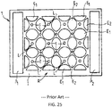
- FIG. 25 is a duplicate of FIG. 1 included in Patent Literature 1.
- Patent Literature 1 discloses a dielectrophoresis system of handling dielectric particles, particularly biological cells, which are suspended in a medium and subjected to the action of an alternating electrical field. The distribution of said field is made non-uniform using a regular network (R) of electrodes (E1, E2) which can define local areas (L) where the electrical field is minimum in order to concentrate particles in said local zones (L) as a result of the action of the negative dielectrophoresis forces.
- the inventive system is characterised in that the network (R) of electrodes (E1, E2) is formed on the surface of a multi-layered support (1).
- said system is characterised in that the electrodes (E1, E2) in the network (R) having the same polarity are linked to a common power supply contact (P1, P2) via two networks (R1, R2) of strip conductors (C1, C2) which are formed at an intermediary level located below the network (R) of electrodes.
- Patent Literature 1 Japanese Patent Application Publication No. 2005-506 191
- An object of the present invention is to provide a concentration device suitable for dielectrophoresis and a method for concentrating particles with the same.
- the present invention provides a concentration device suitable for dielectrophoresis, comprising:
- the present invention provides a concentration device suitable for dielectrophoresis and a method for concentrating particles with the same.
- FIG. 1A shows a top view of a concentration device according to the embodiment.
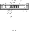
- FIG. 1B shows a cross-sectional view taken along the line 1B-1B included in FIG. 1A .
- FIG. 1C shows a cross-sectional view taken along the line 1C-1C included in FIG. 1A .
- the concentration device comprises a first substrate 110 and a second substrate 105.
- the second substrate 105 faces the first substrate 110.
- a flow path 103 is formed between the first substrate 110 and the second substrate 105.
- the flow path 103 has a height H and a width W.
- FIG. 1D shows a schematic view of the back surface of the first substrate 110.
- FIG. 1A is a schematic view of the front surface of the first substrate 110.
- the first substrate 110 comprises an inlet 101 and an outlet 102.
- the inlet 101 and the outlet 102 are through-holes.
- the inlet 101 communicates with the outlet 102 through the flow path 103. Therefore, a samples solution is injected through the inlet 101.
- the thus-injected samples solution flows through the flow path 103.
- the samples solution is discharged from the outlet 102.
- the concentration device according to the present embodiment is a chip for concentration (hereinafter, which may be referred to as a "concentration chip").
- the back surface of the first substrate 110 is provided with a first comb-shaped electrode 201 and a second comb-shaped electrode 202.
- the first comb-shaped electrode 201 and the second comb-shaped electrode 202 engage each other.
- the inside of the flow path 103 is provided with first pillar electrodes 301 and second pillar electrodes 302.
- the first pillar electrodes 301 are electrically connected to the first comb-shaped electrode 201.
- the second pillar electrodes 302 are electrically connected to the second comb-shaped electrode 202.
- the first pillar electrodes 301 are electrically insulated from the second comb-shaped electrode 202.
- the second pillar electrodes 302 are electrically insulated from the first comb-shaped electrode 201.
- FIG. 2 shows a top view of the first pillar electrodes 301 and the second pillar electrodes 302.
- each of the first pillar electrodes 301 has a shape of a rugby ball.
- Each of the second pillar electrodes 302 also has a shape of a rugby ball.
- One pillar electrode line 303 is composed of plural first pillar electrodes 301 and plural second pillar electrodes 302.
- one pillar electrode line 303 includes plural first pillar electrodes 301 and plural second pillar electrodes 302.
- Plural pillar electrode lines 303 are formed in the flow path 103.
- Each of the pillar electrode lines 303 is parallel to an X-axis direction. In this way, two or more pillar electrode lines 303 are formed in the flow path 103.
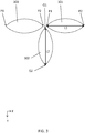
- FIG. 3 shows a top view of two adjacent first pillar electrodes 301 and one second pillar electrode 302 thereby.
- Each of the first pillar electrodes 301 includes a first vertex P1 and a second vertex P2.
- the line segment between the first vertex P1 and the second vertex P2 included in each of the first pillar electrodes 301 has a length L1 in the X-axis direction.
- Each of the second pillar electrodes 302 includes a first vertex Q1 and a second vertex Q2.
- the line segment between the first vertex Q1 and the second vertex Q2 included in each of the second pillar electrodes 302 has a length L2 in the Y-axis direction.
- the first vertex Q1 is near the first vertex P1 and the second vertex P2.
- the second vertex Q2 is far from the first vertex P1 and the second vertex P2.
- the second vertex Q2 included in the second pillar electrode 302 included in the first pillar electrode line 303a is closer to the second pillar electrode line 302b than the first vertex Q1 included in the second pillar electrodes 302 included in the first pillar electrode line 303a.
- a third pillar electrode line 303c may be provided.
- the X-axis direction is perpendicular to the Y-axis direction.
- FIG. 4 shows an enlarged view of a region U surrounded by a dot line included in FIG. 2 .
- FIG. 4 is a drawing showing one pillar electrode group included in the region U. As shown in FIG. 4 , the one pillar electrode group is composed of the following four electrodes (I) - (IV):
- the left-side first pillar electrode 301L and the right-side first pillar electrode 301R are adjacent to each other in such a manner that the second vertex P2 of the left-side first pillar electrode 301L and the first vertex P1 of the right-side first pillar electrode 301R face each other.
- a line which passes through the second vertex P2 of the left-side first pillar electrode 301L and the first vertex P1 of the right-side first pillar electrode 301R is parallel to the X-axis direction.
- a line which passes through the second vertex Q2 of the second pillar electrode A and the first vertex Q1 of the second pillar electrode B is parallel to the Y-axis direction.
- the center point O, the line segment P, and the line segment Q are defined as below.
- the center point O is an intersection point of the line segment P and the line segment Q.
- the four electrodes included in the one pillar electrode group surround the center point O in the top view.
- the line segment Q is a line segment between the second vertex Q2 of the second pillar electrode 302A and the first vertex Q1 of the second pillar electrode 302B.
- the line segment P is a line segment between the second vertex P2 of the left-side first pillar electrode 301L and the first vertex P1 of the right-side first pillar electrode 301R.
- the present embodiment is characterized by that the following mathematical formula (I) is satisfied.
- dielectrophoresis force is given as attractive force to particles flowing through the center point O. For this reason, the particles are captured only at and around the center point O against the stream of the fluid (i.e., the sample solution) flowing through the flow path 103. In this way, the particles are concentrated at and around the center point O.
- dielectrophoresis force is given as repulsive force to the particles flowing through the center point O. For this reason, the repulsive force accelerates the stream of the particles flowing through the flow path 103. Consequently, the particles fail to be captured. The particles flow faster toward the lower course of the flow path 103.
- the value of L3 is not less than 5 micrometers. See FIG. 17 - FIG. 20 .
- the value of A2 is not more than 2.8 micrometers. See FIG. 21 .
- the length of the line segment P is not more than 5.6 micrometers. See FIG. 22 .
- the concentration device according to the embodiment may be fabricated using a common fabrication method of semiconductor devices.
- a first resist 901 is patterned on an upper surface of a silicon substrate 90 comprising an insulating layer 91 at the bottom surface thereof.
- a second resist 902 is further patterned.
- a part of the silicon substrate 90 on which neither the first resist 901 nor the second resist 902 is formed is etched using both of the first resist 901 and the second resist 902 as a mask. A bottom of the etched part is located in the inside of the silicon substrate 90.
- the second resist 902 is removed.
- the silicon substrate 90 is etched using the first resist 901 as a mask.
- the bottom of the etched part reaches a front surface of the insulating layer 91.
- the flow path 103 having the height H and the width W is formed.
- the first resist 901 is removed as shown in FIG. 24F . In this way, the first substrate 110 is formed. After the inlet 102 and the outlet 103 are formed, the first substrate 110 is joined onto the second substrate 105.
- each of the particles has a diameter of not less than 30 nanometers and not more than 100 nanometers.
- An example of the particle is influenza virus (particle size: approximately 100 nanometers) or norovirus (particle size: approximately 30 nanometers).
- the concentration device according to the embodiment is prepared. Specifically, a user of the concentration device purchases the concentration device according to the embodiment from the present patentee or its licensee.
- the sample solution is supplied between the first substrate 110 and the second substrate 105. Specifically, the sample solution is injected through the inlet 101. The injected sample solution flows through the flow path 103.
- an alternating voltage is applied between the first pillar electrodes 301 and the second pillar electrodes 302 through the first comb-shaped electrode 201 and the second comb-shaped electrode 202.
- the applied alternating voltage has a voltage of not less than 5 volts pp and not more than 20 volts pp and a frequency of not less than 50 kilohertz and not more than 20 megahertz.
- pp means peak-to-peak.
- This alternating voltage forms a region having a significantly high electric field at and around the center point O.
- This high electric field gives dielectrophoresis force as the attractive force at and around the center point O. Due to this dielectrophoresis force as the attractive force, the particles are captured only at and around the center point O against the stream of the fluid (namely, the sample solution) flowing through the flow path 103.
- the dielectrophoresis force as attractive force is greater than force given to the particles by the sample solution flowing through the flow path 103 along the +Y direction. In this way, the particles are concentrated center only at and around the center point O. Finally, the sample solution is discharged from the outlet 103, whereas the particles are left at and around the center point O.
- the value of L3 is not less than 5 micrometers.
- dielectrophoresis as the repulsive force given to the particles accelerates the stream of the particles. For this reason, the particles are not captured and flow faster toward the lower course of the flow path (namely, in the +Y direction).
- parallel used in the instant specification may include an angular error of not more than 5 degrees.
- perpendicular may include an angular error of not more than 5 degrees.
- a sample solution containing fluorescence polystyrene particles was used.
- the sample solution was prepared by diluting fluorescence polystyrene particles (available from Polysciences company, trade name: Fluoresbrite Yellow Green Carboxylate Microspheres, particle size: 0.1 micrometer, w/v concentration: 2.6%) 100,000 fold with a 1% Tween20 aqueous solution.
- the sample solution had fluorescence polystyrene particle concentration of approximately 4.7x10 8 ml -1 .
- a SOI substrate was etched as shown in FIG. 24A - FIG. 24F to fabricate a first substrate 110.
- the first substrate 110 was joined onto a second substrate 105.
- a concentration device according to the inventive example 1 was fabricated.
- the following table 1 shows the details of the concentration device according to the inventive example 1.
- Table 1 Number of Pillar Electrode Lines 303 26 Number of First Pillar Electrodes 301 in each pillar electrode line 303 26 Number of Second Pillar Electrodes 302 in each pillar electrode line 303 35 L1 25.5 micrometers L2 25.5 micrometers P 2.8 micrometers Q 31.1 micrometers A1 29.7 micrometers A2 1.4 micrometers L3 28.3 micrometers H 50 micrometers W 1,000 micrometers
- ethanol was supplied at a flow rate of 20 microliters/minute through an inlet 101 for five minutes. In this way, air was removed from the flow path 103. Furthermore, 1% Tween20 aqueous solution was supplied at a flow rate of 20 microliter/minute through the inlet 101 for five minutes. In this way, the ethanol was removed from the flow path 103.
- the flow path 103 was filled with 1% Tween20 aqueous solution.
- FIG. 5 is a fluorescent microscope photograph of the flow path 103 through which the sample solution flowed. At this stage, an alternating voltage was not applied.
- FIG. 6 is a fluorescent microscope photograph of the flow path 103 through which the sample solution flowed while the alternating voltage was applied.
- FIG. 7 is a fluorescent microscope photograph of the flow path 103 after five seconds of an end of the application of the alternating voltage.
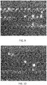
- FIG. 8 - FIG. 10 are fluorescent microscope photographs which correspond to FIG. 5 - FIG. 7 respectively.
- FIG. 8 - FIG. 10 also in the inventive example 2, even if the supply of the sample solution is continued, the particles are concentrated at and around the center point O during the application of the alternating voltage.
- FIG. 11 is a fluorescent microscope photograph taken before an application of an alternating voltage.
- FIG. 12 is a fluorescent microscope photograph taken during the application of the alternating voltage. In both of FIG. 11 and FIG. 12 , the supply of the sample solution was continued. As is clear from FIG. 11 and FIG. 12 , also in the inventive example 3, even if the supply of the sample solution is continued, the influenza virus particles are concentrated at and around the center point O during the application of the alternating voltage.
- the sample solution containing the inactivated influenza virus particles was prepared as below.
- the influenza virus was H1N1 type A/Hyogo/YS/2011 strain contained in allantoic fluid of a chicken egg cultured in graduate School of Veterinary Medicine, Hokkaido University.
- the influenza virus was inactivated using ⁇ -propiolactone.
- the inactivated influenza virus was dyed as below.
- Fluorescent dye from Biotium company, trade name: 30022 CellBriteOrange Cyvertexlasmic Membrane Dye 1 ml Dil cell labeling solution, 5 microliters
- the saline containing the fluorescent dye is mixed with the aqueous solution of the inactivated influenza virus (500 milliliters). In this way, a mixture solution was obtained.
- the mixture solution was left at rest 37 degrees Celsius for 20 minutes. In this way, the inactivated influenza virus was dyed.
- a mannitol aqueous solution (concentration: 280 mM, volume: 1 milliliter) was added to the aqueous solution of the inactivated influenza virus.
- the aqueous solution was filtered with a filter of 0.45 micrometers. In this way, impurities each having a diameter of not less than 0.45 micrometers were removed.
- the aqueous solution was condensed with a centrifugal filter having filtration accuracy of the 100kDa molecular weight so as to have a volume of approximately 60 microliter.
- a mannitol aqueous solution (concentration: 280 mM, volume: 600 microliter) was added so that the aqueous solution had electrical conductivity of 0.78 mS/cm. In this way, the sample solution containing the inactivated influenza virus was prepared.
- FIG. 13 is a top view showing the simulation results in the simulation example A1.
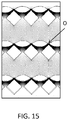
- An electric field increases with an increase in the density of black dots.
- a region having a significantly high electric field is formed at and around the center point O.
- FIG. 14 is a top view showing the simulation results in the simulation example A2. As is clear from FIG. 14 , a region having a significantly high electric field is formed at and around the center point O.
- FIG. 15 is a top view showing the simulation results in the simulation example A3. As is clear from FIG. 15 , a region having a significantly high electric field is formed at and around the center point O.
- the top-view shape of the first pillar electrodes 301 and the second pillar electrodes 302 is not limited, as far as the following four requirements (I) - (IV) are satisfied.
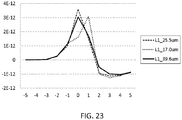
- the distance between the particle and the center point O is defined as a negative value.
- the distance between the particle and the center point O is defined as a positive value.
- the direction in which the sample solution flows through the flow path 103 is the +Y direction.
- FIG. 17 is a graph showing the results of the simulation example B1.
- the horizontal axis represents the distance between the center point O and the particle located on the straight line LL.
- the vertical axis represents the dielectrophoresis force given to the particle.
- the positive value represents dielectrophoresis force as attractive force.
- the negative value represents dielectrophoresis force as repulsive force.
- the attractive force is given to the particle to draw the particle to the center point O in the upper region of the graph shown in FIG. 17 .
- the repulsive force given to the particle to keep the particle away from the center point O in the lower region of the graph shown in FIG. 17 .
- dielectrophoresis force is given to the particles as attractive force. Due to dielectrophoresis force as attractive force, the particles are captured only at and around the center point O against the stream of the fluid (namely, the sample solution) flowing through the flow path 103. In this way, the particles are concentrated only at and around the center point O.
- dielectrophoresis force is given as repulsive force to the particles, while the particles approaches the center point O along the stream of the fluid (namely, the sample solution) flowing through the flow path 103.
- the dielectrophoresis force given as repulsive force accelerates the speed of the particles. For this reason, the particles fail to be captured and flow toward the lower course of the flow path 103. Therefore, the particles fail to be concentrated.
- FIG. 18 is a graph showing the results of the simulation example B2.
- the dielectrophoresis force as the attractive force is given to the particles. Therefore, the particles are concentrated only at and around the center point O.
- the dielectrophoresis force is given as repulsive force to the particles, while the particles approaches the center point O along the stream of the fluid (namely, the sample solution) flowing through the flow path 103. Therefore, the particles fail to be concentrated.
- FIG. 19 is a graph showing the results of the simulation example B3.
- the dielectrophoresis force as the attractive force is given to the particles. Therefore, the particles are concentrated only at and around the center point O.
- the dielectrophoresis force is given as repulsive force to the particles, while the particles approaches the center point O along the stream of the fluid (namely, the sample solution) flowing through the flow path 103. Therefore, the particles fail to be concentrated.
- FIG. 20 is a graph showing the results of the simulation example B4.
- the dielectrophoresis force as the attractive force is given to the particles. Therefore, the particles are concentrated only at and around the center point O.
- the dielectrophoresis force is given as repulsive force to the particles, while the particles approaches the center point O along the stream of the fluid (namely, the sample solution) flowing through the flow path 103. Therefore, the particles fail to be concentrated.
- FIG. 21 is a graph showing the results of the simulation example B5.
- FIG. 22 is a graph showing the results of the simulation example B6.
- FIG. 23 is a graph showing the results of the simulation example B7.
- the present invention can be used for a sensor for concentrating a virus having low concentration.
Landscapes
- Chemical & Material Sciences (AREA)
- Health & Medical Sciences (AREA)
- Life Sciences & Earth Sciences (AREA)
- General Health & Medical Sciences (AREA)
- Chemical Kinetics & Catalysis (AREA)
- Engineering & Computer Science (AREA)
- Bioinformatics & Cheminformatics (AREA)
- Organic Chemistry (AREA)
- Hematology (AREA)
- Clinical Laboratory Science (AREA)
- Zoology (AREA)
- Wood Science & Technology (AREA)
- Analytical Chemistry (AREA)
- Genetics & Genomics (AREA)
- Dispersion Chemistry (AREA)
- Electrochemistry (AREA)
- Molecular Biology (AREA)
- Immunology (AREA)
- General Engineering & Computer Science (AREA)
- Virology (AREA)
- Microbiology (AREA)
- Fluid Mechanics (AREA)
- Physics & Mathematics (AREA)
- Biochemistry (AREA)
- Biotechnology (AREA)
- Microelectronics & Electronic Packaging (AREA)
- Biomedical Technology (AREA)
- Medicinal Chemistry (AREA)
- Apparatus Associated With Microorganisms And Enzymes (AREA)
- Electrostatic Separation (AREA)
- Micro-Organisms Or Cultivation Processes Thereof (AREA)
- Investigating Or Analyzing Materials By The Use Of Electric Means (AREA)
Applications Claiming Priority (2)
| Application Number | Priority Date | Filing Date | Title |
|---|---|---|---|
| JP2016206610 | 2016-10-21 | ||
| PCT/JP2017/010339 WO2018073991A1 (ja) | 2016-10-21 | 2017-03-15 | 誘電泳動に適した濃縮装置およびそれを用いて粒子を濃縮する方法 |
Publications (3)
| Publication Number | Publication Date |
|---|---|
| EP3530342A1 true EP3530342A1 (de) | 2019-08-28 |
| EP3530342A4 EP3530342A4 (de) | 2019-10-09 |
| EP3530342B1 EP3530342B1 (de) | 2020-04-29 |
Family
ID=62018410
Family Applications (1)
| Application Number | Title | Priority Date | Filing Date |
|---|---|---|---|
| EP17862471.4A Active EP3530342B1 (de) | 2016-10-21 | 2017-03-15 | Konzentrationsvorrichtung für dielektrophorese und verfahren zur konzentration von partikeln damit |
Country Status (5)
| Country | Link |
|---|---|
| US (1) | US11198140B2 (de) |
| EP (1) | EP3530342B1 (de) |
| JP (1) | JP6811381B2 (de) |
| CN (1) | CN109475817B (de) |
| WO (1) | WO2018073991A1 (de) |
Families Citing this family (1)
| Publication number | Priority date | Publication date | Assignee | Title |
|---|---|---|---|---|
| EP3919171A1 (de) | 2020-06-05 | 2021-12-08 | Ecole Polytechnique Fédérale de Lausanne (EPFL) | Dielektrophoresedetektionsvorrichtung |
Family Cites Families (8)
| Publication number | Priority date | Publication date | Assignee | Title |
|---|---|---|---|---|
| FR2831084B1 (fr) * | 2001-10-22 | 2004-08-27 | Centre Nat Rech Scient | Procede et systeme pour manipuler par dielectrophorese des particules dielectriques, en particulier des cellules biologiques |
| US20040011650A1 (en) * | 2002-07-22 | 2004-01-22 | Frederic Zenhausern | Method and apparatus for manipulating polarizable analytes via dielectrophoresis |
| GB0303305D0 (en) * | 2003-02-12 | 2003-03-19 | Secr Defence | Apparatus for collecting particles |
| KR100745754B1 (ko) * | 2005-12-29 | 2007-08-02 | 삼성전자주식회사 | 금속 기둥 전극 구조를 포함하는 유전 영동을 이용하여입자를 조작하기 위한 장치 및 그를 이용하여 빠른유속으로 유전 영동에 의하여 입자를 조작할 수 있는 방법 |
| JP5750661B2 (ja) * | 2009-01-23 | 2015-07-22 | 学校法人 芝浦工業大学 | 三次元誘電泳動デバイス |
| JP5700598B2 (ja) * | 2011-11-09 | 2015-04-15 | 株式会社日立製作所 | 微粒子分離装置及び方法 |
| CN205288112U (zh) * | 2015-12-29 | 2016-06-08 | 王冰 | 一种向外部发射非均电场的介电电泳电极结构 |
| CN105664720A (zh) * | 2016-03-23 | 2016-06-15 | 内蒙古天一环境技术有限公司 | 一种使用柱状介电电泳电极的平板膜池及膜浓缩系统 |
-
2017
- 2017-03-15 EP EP17862471.4A patent/EP3530342B1/de active Active
- 2017-03-15 WO PCT/JP2017/010339 patent/WO2018073991A1/ja not_active Ceased
- 2017-03-15 JP JP2018546139A patent/JP6811381B2/ja active Active
- 2017-03-15 CN CN201780043889.3A patent/CN109475817B/zh active Active
-
2019
- 2019-01-08 US US16/241,995 patent/US11198140B2/en active Active
Also Published As
| Publication number | Publication date |
|---|---|
| JPWO2018073991A1 (ja) | 2019-08-08 |
| US20190134645A1 (en) | 2019-05-09 |
| EP3530342B1 (de) | 2020-04-29 |
| CN109475817B (zh) | 2021-11-16 |
| US11198140B2 (en) | 2021-12-14 |
| EP3530342A4 (de) | 2019-10-09 |
| CN109475817A (zh) | 2019-03-15 |
| WO2018073991A1 (ja) | 2018-04-26 |
| JP6811381B2 (ja) | 2021-01-13 |
Similar Documents
| Publication | Publication Date | Title |
|---|---|---|
| US9192944B2 (en) | Methods, systems and apparatus for size-based particle separation | |
| Arjmandi et al. | Measuring the electric charge and zeta potential of nanometer-sized objects using pyramidal-shaped nanopores | |
| US20110108424A1 (en) | Device for separating biomolecules from a fluid | |
| Elnathan et al. | Versatile particle-based route to engineer vertically aligned silicon nanowire arrays and nanoscale pores | |
| CN114770800B (zh) | 一种结合确定性侧向位移和介电泳的微塑料颗粒筛选与分离装置及方法 | |
| US11806729B2 (en) | Hyper efficient separations device | |
| US20140031995A1 (en) | Control method and device to control movement speed of a substance and use thereof | |
| Zhao et al. | Sorting of heterogeneous colloids by AC-dielectrophoretic forces in a microfluidic chip with asymmetric orifices | |
| Gracheva et al. | Multilayered semiconductor membranes for nanopore ionic conductance modulation | |
| US11198140B2 (en) | Concentration device suitable for dielectrophoresis and method for concentrating particles with the same | |
| JP2017053808A (ja) | 半導体分析チップ及び微粒子検査方法 | |
| CN111250182B (zh) | 一种高通量微流控电泳筛分芯片及其制备方法、应用方法 | |
| WO2020219593A1 (en) | Dielectrophoretic immobilization of a particle in proximity to a cavity for interfacing | |
| Hill et al. | On the potential of microscale electrokinetic cascade devices | |
| Song et al. | Dean Flow-Assisted microfluidic aqueous Two-Phase extraction for purifying extracellular vesicles and facilitating single-vesicle analysis | |
| US20200061540A1 (en) | Nanocarbon separation apparatus and nanocarbon separation method | |
| US11642627B2 (en) | Nanocarbon separation device, nanocarbon separation method, and electrode tube | |
| Akagi et al. | Development of a polymer-based easy-to-fabricate micro-free-flow electrophoresis device | |
| Farajollahi et al. | Electrochemically-driven insertion of biological nanodiscs into solid state membrane pores as a basis for “pore-in-pore” membranes | |
| KR102077643B1 (ko) | 메니스커스 곡면을 갖는 시료 내 입자 분리 장치 및 방법 | |
| JP2005249739A (ja) | 電気浸透フローセル、絶縁体シート及び電気浸透フローセルチップ | |
| US20250345797A1 (en) | Microfluidic devices and methods for sorting particles such as extracellular vesicles in a sample | |
| McEnnis et al. | Solid particles adsorbed on capillary-bridge-shaped fluid polystyrene surfaces | |
| US8506783B2 (en) | Three-dimensional nanochannel device and method of manufacturing the same | |
| Yoon et al. | Elastomeric deformation-assisted nanochannel fabrication using electrospun polymer fibers for micro/nanofluidic system |
Legal Events
| Date | Code | Title | Description |
|---|---|---|---|
| STAA | Information on the status of an ep patent application or granted ep patent |
Free format text: STATUS: THE INTERNATIONAL PUBLICATION HAS BEEN MADE |
|
| PUAI | Public reference made under article 153(3) epc to a published international application that has entered the european phase |
Free format text: ORIGINAL CODE: 0009012 |
|
| STAA | Information on the status of an ep patent application or granted ep patent |
Free format text: STATUS: REQUEST FOR EXAMINATION WAS MADE |
|
| 17P | Request for examination filed |
Effective date: 20190322 |
|
| AK | Designated contracting states |
Kind code of ref document: A1 Designated state(s): AL AT BE BG CH CY CZ DE DK EE ES FI FR GB GR HR HU IE IS IT LI LT LU LV MC MK MT NL NO PL PT RO RS SE SI SK SM TR |
|
| AX | Request for extension of the european patent |
Extension state: BA ME |
|
| A4 | Supplementary search report drawn up and despatched |
Effective date: 20190909 |
|
| RIC1 | Information provided on ipc code assigned before grant |
Ipc: B01L 3/00 20060101ALI20190903BHEP Ipc: C12N 7/00 20060101ALI20190903BHEP Ipc: B03C 5/02 20060101ALI20190903BHEP Ipc: B01D 57/02 20060101AFI20190903BHEP Ipc: C12N 7/02 20060101ALI20190903BHEP Ipc: B03C 5/00 20060101ALI20190903BHEP |
|
| GRAP | Despatch of communication of intention to grant a patent |
Free format text: ORIGINAL CODE: EPIDOSNIGR1 |
|
| STAA | Information on the status of an ep patent application or granted ep patent |
Free format text: STATUS: GRANT OF PATENT IS INTENDED |
|
| RIC1 | Information provided on ipc code assigned before grant |
Ipc: B03C 5/02 20060101ALI20191101BHEP Ipc: B01D 57/02 20060101AFI20191101BHEP Ipc: C12N 7/00 20060101ALI20191101BHEP Ipc: B03C 5/00 20060101ALI20191101BHEP Ipc: C12N 7/02 20060101ALI20191101BHEP Ipc: B01L 3/00 20060101ALI20191101BHEP |
|
| DAV | Request for validation of the european patent (deleted) | ||
| DAX | Request for extension of the european patent (deleted) | ||
| INTG | Intention to grant announced |
Effective date: 20191119 |
|
| GRAS | Grant fee paid |
Free format text: ORIGINAL CODE: EPIDOSNIGR3 |
|
| GRAA | (expected) grant |
Free format text: ORIGINAL CODE: 0009210 |
|
| STAA | Information on the status of an ep patent application or granted ep patent |
Free format text: STATUS: THE PATENT HAS BEEN GRANTED |
|
| AK | Designated contracting states |
Kind code of ref document: B1 Designated state(s): AL AT BE BG CH CY CZ DE DK EE ES FI FR GB GR HR HU IE IS IT LI LT LU LV MC MK MT NL NO PL PT RO RS SE SI SK SM TR |
|
| REG | Reference to a national code |
Ref country code: GB Ref legal event code: FG4D |
|
| REG | Reference to a national code |
Ref country code: CH Ref legal event code: EP |
|
| REG | Reference to a national code |
Ref country code: DE Ref legal event code: R096 Ref document number: 602017015885 Country of ref document: DE |
|
| REG | Reference to a national code |
Ref country code: AT Ref legal event code: REF Ref document number: 1262451 Country of ref document: AT Kind code of ref document: T Effective date: 20200515 |
|
| REG | Reference to a national code |
Ref country code: IE Ref legal event code: FG4D |
|
| REG | Reference to a national code |
Ref country code: NL Ref legal event code: MP Effective date: 20200429 |
|
| REG | Reference to a national code |
Ref country code: LT Ref legal event code: MG4D |
|
| PG25 | Lapsed in a contracting state [announced via postgrant information from national office to epo] |
Ref country code: LT Free format text: LAPSE BECAUSE OF FAILURE TO SUBMIT A TRANSLATION OF THE DESCRIPTION OR TO PAY THE FEE WITHIN THE PRESCRIBED TIME-LIMIT Effective date: 20200429 Ref country code: FI Free format text: LAPSE BECAUSE OF FAILURE TO SUBMIT A TRANSLATION OF THE DESCRIPTION OR TO PAY THE FEE WITHIN THE PRESCRIBED TIME-LIMIT Effective date: 20200429 Ref country code: SE Free format text: LAPSE BECAUSE OF FAILURE TO SUBMIT A TRANSLATION OF THE DESCRIPTION OR TO PAY THE FEE WITHIN THE PRESCRIBED TIME-LIMIT Effective date: 20200429 Ref country code: IS Free format text: LAPSE BECAUSE OF FAILURE TO SUBMIT A TRANSLATION OF THE DESCRIPTION OR TO PAY THE FEE WITHIN THE PRESCRIBED TIME-LIMIT Effective date: 20200829 Ref country code: NO Free format text: LAPSE BECAUSE OF FAILURE TO SUBMIT A TRANSLATION OF THE DESCRIPTION OR TO PAY THE FEE WITHIN THE PRESCRIBED TIME-LIMIT Effective date: 20200729 Ref country code: PT Free format text: LAPSE BECAUSE OF FAILURE TO SUBMIT A TRANSLATION OF THE DESCRIPTION OR TO PAY THE FEE WITHIN THE PRESCRIBED TIME-LIMIT Effective date: 20200831 Ref country code: GR Free format text: LAPSE BECAUSE OF FAILURE TO SUBMIT A TRANSLATION OF THE DESCRIPTION OR TO PAY THE FEE WITHIN THE PRESCRIBED TIME-LIMIT Effective date: 20200730 |
|
| REG | Reference to a national code |
Ref country code: AT Ref legal event code: MK05 Ref document number: 1262451 Country of ref document: AT Kind code of ref document: T Effective date: 20200429 |
|
| PG25 | Lapsed in a contracting state [announced via postgrant information from national office to epo] |
Ref country code: HR Free format text: LAPSE BECAUSE OF FAILURE TO SUBMIT A TRANSLATION OF THE DESCRIPTION OR TO PAY THE FEE WITHIN THE PRESCRIBED TIME-LIMIT Effective date: 20200429 Ref country code: RS Free format text: LAPSE BECAUSE OF FAILURE TO SUBMIT A TRANSLATION OF THE DESCRIPTION OR TO PAY THE FEE WITHIN THE PRESCRIBED TIME-LIMIT Effective date: 20200429 Ref country code: LV Free format text: LAPSE BECAUSE OF FAILURE TO SUBMIT A TRANSLATION OF THE DESCRIPTION OR TO PAY THE FEE WITHIN THE PRESCRIBED TIME-LIMIT Effective date: 20200429 Ref country code: BG Free format text: LAPSE BECAUSE OF FAILURE TO SUBMIT A TRANSLATION OF THE DESCRIPTION OR TO PAY THE FEE WITHIN THE PRESCRIBED TIME-LIMIT Effective date: 20200729 |
|
| PG25 | Lapsed in a contracting state [announced via postgrant information from national office to epo] |
Ref country code: NL Free format text: LAPSE BECAUSE OF FAILURE TO SUBMIT A TRANSLATION OF THE DESCRIPTION OR TO PAY THE FEE WITHIN THE PRESCRIBED TIME-LIMIT Effective date: 20200429 Ref country code: AL Free format text: LAPSE BECAUSE OF FAILURE TO SUBMIT A TRANSLATION OF THE DESCRIPTION OR TO PAY THE FEE WITHIN THE PRESCRIBED TIME-LIMIT Effective date: 20200429 |
|
| PG25 | Lapsed in a contracting state [announced via postgrant information from national office to epo] |
Ref country code: IT Free format text: LAPSE BECAUSE OF FAILURE TO SUBMIT A TRANSLATION OF THE DESCRIPTION OR TO PAY THE FEE WITHIN THE PRESCRIBED TIME-LIMIT Effective date: 20200429 Ref country code: SM Free format text: LAPSE BECAUSE OF FAILURE TO SUBMIT A TRANSLATION OF THE DESCRIPTION OR TO PAY THE FEE WITHIN THE PRESCRIBED TIME-LIMIT Effective date: 20200429 Ref country code: EE Free format text: LAPSE BECAUSE OF FAILURE TO SUBMIT A TRANSLATION OF THE DESCRIPTION OR TO PAY THE FEE WITHIN THE PRESCRIBED TIME-LIMIT Effective date: 20200429 Ref country code: DK Free format text: LAPSE BECAUSE OF FAILURE TO SUBMIT A TRANSLATION OF THE DESCRIPTION OR TO PAY THE FEE WITHIN THE PRESCRIBED TIME-LIMIT Effective date: 20200429 Ref country code: ES Free format text: LAPSE BECAUSE OF FAILURE TO SUBMIT A TRANSLATION OF THE DESCRIPTION OR TO PAY THE FEE WITHIN THE PRESCRIBED TIME-LIMIT Effective date: 20200429 Ref country code: AT Free format text: LAPSE BECAUSE OF FAILURE TO SUBMIT A TRANSLATION OF THE DESCRIPTION OR TO PAY THE FEE WITHIN THE PRESCRIBED TIME-LIMIT Effective date: 20200429 Ref country code: CZ Free format text: LAPSE BECAUSE OF FAILURE TO SUBMIT A TRANSLATION OF THE DESCRIPTION OR TO PAY THE FEE WITHIN THE PRESCRIBED TIME-LIMIT Effective date: 20200429 Ref country code: RO Free format text: LAPSE BECAUSE OF FAILURE TO SUBMIT A TRANSLATION OF THE DESCRIPTION OR TO PAY THE FEE WITHIN THE PRESCRIBED TIME-LIMIT Effective date: 20200429 |
|
| REG | Reference to a national code |
Ref country code: DE Ref legal event code: R097 Ref document number: 602017015885 Country of ref document: DE |
|
| PG25 | Lapsed in a contracting state [announced via postgrant information from national office to epo] |
Ref country code: PL Free format text: LAPSE BECAUSE OF FAILURE TO SUBMIT A TRANSLATION OF THE DESCRIPTION OR TO PAY THE FEE WITHIN THE PRESCRIBED TIME-LIMIT Effective date: 20200429 Ref country code: SK Free format text: LAPSE BECAUSE OF FAILURE TO SUBMIT A TRANSLATION OF THE DESCRIPTION OR TO PAY THE FEE WITHIN THE PRESCRIBED TIME-LIMIT Effective date: 20200429 |
|
| PLBE | No opposition filed within time limit |
Free format text: ORIGINAL CODE: 0009261 |
|
| STAA | Information on the status of an ep patent application or granted ep patent |
Free format text: STATUS: NO OPPOSITION FILED WITHIN TIME LIMIT |
|
| 26N | No opposition filed |
Effective date: 20210201 |
|
| PG25 | Lapsed in a contracting state [announced via postgrant information from national office to epo] |
Ref country code: MC Free format text: LAPSE BECAUSE OF FAILURE TO SUBMIT A TRANSLATION OF THE DESCRIPTION OR TO PAY THE FEE WITHIN THE PRESCRIBED TIME-LIMIT Effective date: 20200429 |
|
| REG | Reference to a national code |
Ref country code: CH Ref legal event code: PL |
|
| GBPC | Gb: european patent ceased through non-payment of renewal fee |
Effective date: 20210315 |
|
| REG | Reference to a national code |
Ref country code: BE Ref legal event code: MM Effective date: 20210331 |
|
| PG25 | Lapsed in a contracting state [announced via postgrant information from national office to epo] |
Ref country code: CH Free format text: LAPSE BECAUSE OF NON-PAYMENT OF DUE FEES Effective date: 20210331 Ref country code: LI Free format text: LAPSE BECAUSE OF NON-PAYMENT OF DUE FEES Effective date: 20210331 Ref country code: LU Free format text: LAPSE BECAUSE OF NON-PAYMENT OF DUE FEES Effective date: 20210315 Ref country code: IE Free format text: LAPSE BECAUSE OF NON-PAYMENT OF DUE FEES Effective date: 20210315 Ref country code: GB Free format text: LAPSE BECAUSE OF NON-PAYMENT OF DUE FEES Effective date: 20210315 Ref country code: FR Free format text: LAPSE BECAUSE OF NON-PAYMENT OF DUE FEES Effective date: 20210331 |
|
| PG25 | Lapsed in a contracting state [announced via postgrant information from national office to epo] |
Ref country code: BE Free format text: LAPSE BECAUSE OF NON-PAYMENT OF DUE FEES Effective date: 20210331 |
|
| PG25 | Lapsed in a contracting state [announced via postgrant information from national office to epo] |
Ref country code: CY Free format text: LAPSE BECAUSE OF FAILURE TO SUBMIT A TRANSLATION OF THE DESCRIPTION OR TO PAY THE FEE WITHIN THE PRESCRIBED TIME-LIMIT Effective date: 20200429 |
|
| PG25 | Lapsed in a contracting state [announced via postgrant information from national office to epo] |
Ref country code: HU Free format text: LAPSE BECAUSE OF FAILURE TO SUBMIT A TRANSLATION OF THE DESCRIPTION OR TO PAY THE FEE WITHIN THE PRESCRIBED TIME-LIMIT; INVALID AB INITIO Effective date: 20170315 |
|
| PG25 | Lapsed in a contracting state [announced via postgrant information from national office to epo] |
Ref country code: SI Free format text: LAPSE BECAUSE OF FAILURE TO SUBMIT A TRANSLATION OF THE DESCRIPTION OR TO PAY THE FEE WITHIN THE PRESCRIBED TIME-LIMIT Effective date: 20200429 |
|
| PG25 | Lapsed in a contracting state [announced via postgrant information from national office to epo] |
Ref country code: MK Free format text: LAPSE BECAUSE OF FAILURE TO SUBMIT A TRANSLATION OF THE DESCRIPTION OR TO PAY THE FEE WITHIN THE PRESCRIBED TIME-LIMIT Effective date: 20200429 |
|
| PG25 | Lapsed in a contracting state [announced via postgrant information from national office to epo] |
Ref country code: MT Free format text: LAPSE BECAUSE OF FAILURE TO SUBMIT A TRANSLATION OF THE DESCRIPTION OR TO PAY THE FEE WITHIN THE PRESCRIBED TIME-LIMIT Effective date: 20200429 |
|
| PGFP | Annual fee paid to national office [announced via postgrant information from national office to epo] |
Ref country code: DE Payment date: 20250319 Year of fee payment: 9 |
|
| PG25 | Lapsed in a contracting state [announced via postgrant information from national office to epo] |
Ref country code: TR Free format text: LAPSE BECAUSE OF FAILURE TO SUBMIT A TRANSLATION OF THE DESCRIPTION OR TO PAY THE FEE WITHIN THE PRESCRIBED TIME-LIMIT Effective date: 20200429 |