EP3530338A2 - Dépoussiéreur - Google Patents
Dépoussiéreur Download PDFInfo
- Publication number
- EP3530338A2 EP3530338A2 EP19158495.2A EP19158495A EP3530338A2 EP 3530338 A2 EP3530338 A2 EP 3530338A2 EP 19158495 A EP19158495 A EP 19158495A EP 3530338 A2 EP3530338 A2 EP 3530338A2
- Authority
- EP
- European Patent Office
- Prior art keywords
- filter
- clamp
- depression
- flange
- clamping
- Prior art date
- Legal status (The legal status is an assumption and is not a legal conclusion. Google has not performed a legal analysis and makes no representation as to the accuracy of the status listed.)
- Withdrawn
Links
Images





Classifications
-
- B—PERFORMING OPERATIONS; TRANSPORTING
- B01—PHYSICAL OR CHEMICAL PROCESSES OR APPARATUS IN GENERAL
- B01D—SEPARATION
- B01D46/00—Filters or filtering processes specially modified for separating dispersed particles from gases or vapours
- B01D46/0002—Casings; Housings; Frame constructions
- B01D46/0005—Mounting of filtering elements within casings, housings or frames
-
- B—PERFORMING OPERATIONS; TRANSPORTING
- B01—PHYSICAL OR CHEMICAL PROCESSES OR APPARATUS IN GENERAL
- B01D—SEPARATION
- B01D46/00—Filters or filtering processes specially modified for separating dispersed particles from gases or vapours
- B01D46/42—Auxiliary equipment or operation thereof
- B01D46/4227—Manipulating filters or filter elements, e.g. handles or extracting tools
-
- B—PERFORMING OPERATIONS; TRANSPORTING
- B01—PHYSICAL OR CHEMICAL PROCESSES OR APPARATUS IN GENERAL
- B01D—SEPARATION
- B01D46/00—Filters or filtering processes specially modified for separating dispersed particles from gases or vapours
- B01D46/24—Particle separators, e.g. dust precipitators, using rigid hollow filter bodies
- B01D46/2403—Particle separators, e.g. dust precipitators, using rigid hollow filter bodies characterised by the physical shape or structure of the filtering element
- B01D46/2411—Filter cartridges
-
- B—PERFORMING OPERATIONS; TRANSPORTING
- B01—PHYSICAL OR CHEMICAL PROCESSES OR APPARATUS IN GENERAL
- B01D—SEPARATION
- B01D46/00—Filters or filtering processes specially modified for separating dispersed particles from gases or vapours
- B01D46/24—Particle separators, e.g. dust precipitators, using rigid hollow filter bodies
- B01D46/2403—Particle separators, e.g. dust precipitators, using rigid hollow filter bodies characterised by the physical shape or structure of the filtering element
- B01D46/2411—Filter cartridges
- B01D46/2414—End caps including additional functions or special forms
-
- B—PERFORMING OPERATIONS; TRANSPORTING
- B01—PHYSICAL OR CHEMICAL PROCESSES OR APPARATUS IN GENERAL
- B01D—SEPARATION
- B01D46/00—Filters or filtering processes specially modified for separating dispersed particles from gases or vapours
- B01D46/42—Auxiliary equipment or operation thereof
- B01D46/48—Removing dust other than cleaning filters, e.g. by using collecting trays
-
- B—PERFORMING OPERATIONS; TRANSPORTING
- B01—PHYSICAL OR CHEMICAL PROCESSES OR APPARATUS IN GENERAL
- B01D—SEPARATION
- B01D46/00—Filters or filtering processes specially modified for separating dispersed particles from gases or vapours
- B01D46/52—Particle separators, e.g. dust precipitators, using filters embodying folded corrugated or wound sheet material
- B01D46/521—Particle separators, e.g. dust precipitators, using filters embodying folded corrugated or wound sheet material using folded, pleated material
-
- B—PERFORMING OPERATIONS; TRANSPORTING
- B01—PHYSICAL OR CHEMICAL PROCESSES OR APPARATUS IN GENERAL
- B01D—SEPARATION
- B01D46/00—Filters or filtering processes specially modified for separating dispersed particles from gases or vapours
- B01D46/56—Filters or filtering processes specially modified for separating dispersed particles from gases or vapours with multiple filtering elements, characterised by their mutual disposition
- B01D46/58—Filters or filtering processes specially modified for separating dispersed particles from gases or vapours with multiple filtering elements, characterised by their mutual disposition connected in parallel
-
- B—PERFORMING OPERATIONS; TRANSPORTING
- B01—PHYSICAL OR CHEMICAL PROCESSES OR APPARATUS IN GENERAL
- B01D—SEPARATION
- B01D46/00—Filters or filtering processes specially modified for separating dispersed particles from gases or vapours
- B01D46/66—Regeneration of the filtering material or filter elements inside the filter
- B01D46/70—Regeneration of the filtering material or filter elements inside the filter by acting counter-currently on the filtering surface, e.g. by flushing on the non-cake side of the filter
- B01D46/71—Regeneration of the filtering material or filter elements inside the filter by acting counter-currently on the filtering surface, e.g. by flushing on the non-cake side of the filter with pressurised gas, e.g. pulsed air
-
- B—PERFORMING OPERATIONS; TRANSPORTING
- B01—PHYSICAL OR CHEMICAL PROCESSES OR APPARATUS IN GENERAL
- B01D—SEPARATION
- B01D46/00—Filters or filtering processes specially modified for separating dispersed particles from gases or vapours
- B01D46/88—Replacing filter elements
-
- B—PERFORMING OPERATIONS; TRANSPORTING
- B01—PHYSICAL OR CHEMICAL PROCESSES OR APPARATUS IN GENERAL
- B01D—SEPARATION
- B01D2265/00—Casings, housings or mounting for filters specially adapted for separating dispersed particles from gases or vapours
- B01D2265/02—Non-permanent measures for connecting different parts of the filter
- B01D2265/024—Mounting aids
- B01D2265/025—Mounting aids making use of ramps or cams
-
- B—PERFORMING OPERATIONS; TRANSPORTING
- B01—PHYSICAL OR CHEMICAL PROCESSES OR APPARATUS IN GENERAL
- B01D—SEPARATION
- B01D2267/00—Multiple filter elements specially adapted for separating dispersed particles from gases or vapours
-
- B—PERFORMING OPERATIONS; TRANSPORTING
- B01—PHYSICAL OR CHEMICAL PROCESSES OR APPARATUS IN GENERAL
- B01D—SEPARATION
- B01D2271/00—Sealings for filters specially adapted for separating dispersed particles from gases or vapours
- B01D2271/02—Gaskets, sealings
-
- B—PERFORMING OPERATIONS; TRANSPORTING
- B01—PHYSICAL OR CHEMICAL PROCESSES OR APPARATUS IN GENERAL
- B01D—SEPARATION
- B01D2271/00—Sealings for filters specially adapted for separating dispersed particles from gases or vapours
- B01D2271/02—Gaskets, sealings
- B01D2271/022—Axial sealings
Definitions
- the invention is related to a dust collector according to claims 1 and 6 and to an air filter according to claim 12.
- Embodiments of the present invention relate to dust collectors and air filters for use in dust collectors.
- Dust collectors can be installed in fume extraction systems. Certain industrial processes, such as welding, hardfacing, or plasma cutting can generate fumes and dust. Fume extraction systems can remove the fumes and dust from a space (e.g., a work area). Prior to discharging the removed air to another space or outdoors, the air can be passed through a dust collector.
- the dust collector is an enclosure containing air filters for cleaning the air of certain solid contaminants entrained in the air.
- a tube sheet within the dust collector partitions the enclosure into a clean air compartment and a filter compartment containing contaminated air. The filters are sealed against the tube sheet. Contaminated air enters the filter compartment, passes through the filters, then through an opening in the tube sheet and into the clean air compartment. The cleaned air can be ducted to an appropriate discharge location.
- a dust collector including an enclosure and a tube sheet separating a filter compartment from a clean air compartment within the enclosure.
- the tube sheet forms a filter opening through the tube sheet.
- a filter is located within the filter compartment and includes a filter flange having a filtered air outlet aligned with said filter opening.
- the filter flange includes a first alignment structure located on a first lateral side of the filter flange, and a second alignment structure located on the first lateral side of the filter flange. The first alignment structure is offset from the second alignment structure along the first lateral side of the filter flange.
- a clamping assembly comprises a first filter clamp that is movable between a sealing position for sealing the filter flange against the tube sheet, and a release position.
- the first filter clamp engages the first alignment structure when in the sealing position.
- the clamping assembly comprises a second filter clamp that is offset from the first filter clamp and is movable between the sealing position for sealing the filter flange against the tube sheet, and the release position.
- the second filter clamp engages the second alignment structure when in the sealing position.
- the dust collector includes means for moving both of the first filter clamp and the second filter clamp together between the sealing position and the release position.
- a dust collector including an enclosure and a tube sheet separating a filter compartment from a clean air compartment within the enclosure.
- the tube sheet forms a filter opening through the tube sheet.
- a filter is located within the filter compartment and includes a filter flange having a filtered air outlet aligned with said filter opening.
- the filter flange includes a first alignment depression located on a first lateral side of the filter flange, and a second alignment depression located on the first lateral side of the filter flange. The first alignment depression is offset from the second alignment depression along the first lateral side of the filter flange.
- a clamping assembly comprises a first filter clamp that is movable between a sealing position for sealing the filter flange against the tube sheet, and a release position.
- a clamping surface of the first filter clamp is located within the first alignment depression when the first filter clamp is in the sealing position.
- the clamping assembly comprises a second filter clamp that is movable between the sealing position for sealing the filter flange against the tube sheet, and the release position.
- a clamping surface of the second filter clamp is located within the second alignment depression when the second filter clamp is in the sealing position.
- a rotatable rail is attached to both of the first filter clamp and the second filter clamp and is configured for moving the first filter clamp and the second filter clamp between the sealing position and the release position.
- a locking handle is attached to the rotatable rail for manually rotating the rotatable rail and locking the rotatable rail in the sealing position of the first filter clamp and the second filter clamp.
- an air filter including a filter flange comprising an upper gasketed sealing surface and a lower clamping surface, an end cap, and a filter element located between the lower clamping surface of the filter flange and the end cap.
- a first lateral side of the lower clamping surface of the filter flange includes a first clamping depression and a second clamping depression. The first clamping depression and the second clamping depression are linearly aligned along the first lateral side of the lower clamping surface, and the first clamping depression is offset from the second clamping depression along the first lateral side of the lower clamping surface.
- a second lateral side of the lower clamping surface of the filter flange includes a third clamping depression and a fourth clamping depression, wherein the third clamping depression and the fourth clamping depression are linearly aligned along the second lateral side of the lower clamping surface, and the third clamping depression is offset from the fourth clamping depression along the second lateral side of the lower clamping surface.
- Embodiments of the present invention relate to dust collectors and air filters for use in dust collectors.
- the present invention will now be described with reference to the drawings, wherein like reference numerals are used to refer to like elements throughout. It is to be appreciated that the various drawings are not necessarily drawn to scale from one figure to another nor inside a given figure, and in particular that the size of the components are arbitrarily drawn for facilitating the understanding of the drawings.
- numerous specific details are set forth in order to provide a thorough understanding of the present invention. It may be evident, however, that the present invention can be practiced without these specific details. Additionally, other embodiments of the invention are possible and the invention is capable of being practiced and carried out in ways other than as described.
- the terminology and phraseology used in describing the invention is employed for the purpose of promoting an understanding of the invention and should not be taken as limiting.
- Dust and other contaminants are removed from the contaminated air by the filters within the filter compartment 16.
- the dust can fall into the hopper 14 and be discharged to a receptacle 24.
- the dust collector 10 can include legs 26 to raise the enclosure 12 above the ground, so that the receptacle 24 can be placed beneath the hopper 14.
- the dust collector 10 can include a control panel 28 having a user interface for controlling the operation of the fan 20.
- the control panel 28 can include indicators to inform a user that a filter requires cleaning or replacement (e.g., based on an increased pressure drop across a filter).
- the control panel 28 can also include controls for activating a filter cleaning system.
- the dust collector 10 can utilize blasts of compressed air to "backwash" the filters and dislodge dust from the filter media.
- the dust collector 10 can include a compressed air tank 30 for storing compressed air provided by an air compressor that is a part of the dust collector or located remote from the dust collector. Valves, such as solenoid valves for example, control the discharge of compressed air from the air tank 30 to the filters in a series of pulses during a cleaning cycle.
- the clear air compartment 18 can include respective air nozzles aligned with the filters to direct the air pulses in a reverse direction through the filters.
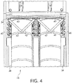
- FIG. 4 is an upward perspective view of the filter compartment 16.
- Each filter 38 has a filter flange 40 located at the top of the filter for sealing the filter against the lower surface of the tube sheet 34 and around the filter openings in the tube sheet.
- the filter compartment 16 includes a clamping system for clamping the filters against the tube sheet 34 and releasing the filters so that they can be replaced.
- the clamping system can be manually operable via interlockable clamp handles 42.
- the clamp handles 42 are shown in the sealing position, with the filter flanges 40 sealed against the tube sheet 34.
- the clamp handles 42 can be locked together at their distal ends to hold the filters 38 in the sealing position.
- the clamp handles 42 can be moved to a release position so that the filters can be removed.
- the distal ends of the clamp handles 42 are unlocked or detached from each other and rotated downward through an acute angle (e.g., approximately 45°).
- an acute angle e.g., approximately 45°.
- the clamp handles 42 are rotated upward through the acute angle, clockwise or counterclockwise, and then locked together.
- the clamping system is configured to seal multiple filters 38 against the tube sheet 34 simultaneously.
- Fig. 4 it can be seen that the left and right portions of the clamping system each clamp two filter flanges 40 against the tube sheet 34.
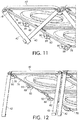
- the clamping of two filter flanges 40 can also be seen in Figs. 11 and 12 .
- the left and right portions of the clamping system are operable to simultaneously clamp an inner filter located adjacent a rear wall of the filter compartment 16, and an outer filter located adjacent the clamp handles 42 and the access opening closed by the door. If desired, clamping system can be configured to clamp fewer or more than four filters simultaneously.
- the clamping system can be attached directly to the tube sheet 34, such as via fasteners, welding, etc., or attached to other structures within the filter compartment 16.
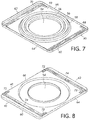
- the filter 38 is shown in detail in Figs. 5-8 .
- the filter element 44 can include a tube of filter media, such as a pleated cellulose media or other known filter materials.
- the lower end of the filter element 44 is capped by an end cap 46.
- the filter flange 40 has a lower clamping surface 48 and an upper gasketed sealing surface 50 that seals against the tube sheet.
- the filter element 44 of the air filter is located between the lower clamping surface 48 of the filter flange 40 and the end cap 46.
- the filter element 44 can be adhered to the filter flange 40 and end cap 46, for example glued to the lower clamping surface 48 and end cap 46, to form air tight connections.
- the filter element 44 can include a series of bands 52 (e.g., polyester bands or other suitable material) to help maintain the cylindrical shape of the filter element, and the filter element can include a cylindrical inner structural cage (not shown) if desired.
- the filter flange 40 can be substantially rectangular in shape, although other shapes are possible, such as square or octagonal for example.
- the filter flange 40 can have rounded or filleted corners and can take the form of a tray having upturned edges to strengthen the filter flange.
- the upper gasketed sealing surface 50 of the filter flange 40 is shown in Fig. 7
- the lower clamping surface 48 is shown in Fig. 8 . It can be seen that the filter flange 40 includes stamped or embossed portions that form depressions in the lower clamping surface 48 and raised surface features in the upper gasketed sealing surface 50.
- the filter flange forms a central aperture 54 that is aligned with a filter opening in the tube sheet to allow filtered air to enter the clean air compartment.
- the central aperture 54 serves as a filtered air outlet for the filter 38.
- the upper gasketed sealing surface 50 of the filter flange 40 can include one or more gaskets 56 surrounding the central aperture 54 to seal flange against the tube sheet. Alternatively, one or more gaskets can be provided on the tube sheet itself.
- the gasket can be formed from an elastomeric material, such as EDPM rubber (ethylene propylene diene monomer rubber) for example.
- the gaskets 56 are concentrically arranged with the central aperture 54 and filter element 44 and are located on a circular raised surface feature 58 on the upper gasketed sealing surface 50.
- the filter flange 40 includes generally C-shaped raised surface features 68, 70 adjacent the forward 60 and rear 62 ends of the filter flange and continuing along the lateral sides 64, 66 for a short distance past the corners of the flange.
- the C-shaped raised surface features 68, 70 can be utilized from the lower clamping surface 48 as handle depressions, and also as alignment structures (e.g., alignment or clamping depressions) that interact with the clamping system to properly position the filter 38 within the dust collector.
- the alignment or clamping depressions 72 in the lower clamping surface 48 can be best seen in Fig. 8 .
- the clamping depressions 72 are located along the lateral sides 64, 66 of the filter flange 40, but could be located at other locations on the filter flange if desired.
- the clamping depressions 72 are linearly aligned with and offset from each other to receive respective clamps in the clamping system.
- the filter element and gaskets are located between the central aperture 54 and the clamping depressions 72, and the clamping depressions can be arranged symmetrically around the central aperture.
- the handle depressions 74 extend between respective pairs of clamping depressions 72 adjacent the forward and rear ends 60, 62 of the filter flange 40.
- the handle depressions 72 need not extend all the way from one clamping depression 72 to another; however doing so allows a handle depression 74 and two clamping depressions 72 to be stamped into the filter flange together by a common die.
- the handle depressions 74 provide a handgrip to aid in inserting and removing the filters 38 from the dust collector, and also help to strengthen the filter flange.
- the filter flange 40 has two handle depressions 74, one at either end 60, 62. Thus, either end 60, 62 of the filter flange 40 can be inserted into the filter compartment first while still providing a handgrip. However, if desired a single handle depression, or no handle depression, can be provided on the filter flange 40.
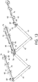
- FIGs 4 and 9 - 14 show details of the filter clamping system in the dust collector 10.
- the clamping system is shown in the release position in Figs. 10 , 12 and 14 , and in the sealing position in Figs. 4 , 9 , 11 and 13 .
- the clamping system includes rotatable rails 76 that are each attached to a respective clamp handle 42 at a proximal end of the clamp handle.
- the filters 38 are inserted onto the rotatable rails 76 with the rails and handles 42 in the release position.
- the rotatable rails 76 can have a generally L-shape as shown in the figures, or another suitable shape (e.g., C-shaped) that is capable of supporting the filter flanges 40.
- Each rotatable rail 76 is sufficiently long to support multiple (e.g., two) filter flanges 40 simultaneously.
- the clamp handles 42 are rotated upward from a vertical orientation in the release position through the acute angle to the sealing position, the filters 38 are lifted upward by rotation of the rails 76 and an upward rotation of filter clamps 78 attached to the rotatable rails 76.
- the filter clamps 78 seat within corresponding clamping depressions 72 in the filter flange to seal the filter flange 40 against the tube sheet 34.
- the filters 38 are incorrectly installed in the dust collector 10, an operator will become aware of the incorrect installation because the filter gaskets 56 will be compressed against the tube sheet 34 before the clamp handles 42 are completely rotated through the acute angle to the sealing position, since the filter clamps 78 will not be located in the clamping depressions 72. The operator will be unable to properly interlock the clamp handles 42 because the distal ends of the clamp handles will be separated. Thus, the clamping depressions 72 serve as alignment structures for the filters 38.
- the filter clamps 78 are configured as curved tabs that project outward and downward from the rotatable rails 76 when the rails are in the release position.
- the curved surfaces of the filter clamps 78 are clamping surfaces that engage the clamping depressions 72 in the filter flanges 40 when the rails 76 are in the sealing position.
- the curved clamping surfaces act as cams that lift the filters 38 vertically as the rotatable rails 76 are rotated through the acute angle to the sealing position.
- the clamping surfaces of the filter clamps 78 are located outside of the clamping depressions 72 in the filter flanges 40 (e.g., located just beneath the clamping depressions), and the filter flanges rest on the rails 76.
- each filter 38 is clamped in the sealing position by four filter clamps 78, two on the left lateral side of the filter and two on the right lateral side of the filter, and each rotatable rail 76 has eight attached filter clamps to seal and release two filters simultaneously. Additional clamps 78 could be utilized for each filter 38, such as three or four per lateral side for example.
- the clamp handles 42 can be interlocked to maintain the filters 38 raised in the sealing position. Interlocking the clamp handles 42 can be done in various ways, such as by using a locking or fastening device (e.g., bolt, lock, shackle, etc.), or via interlocking components located at the distal ends of the clamp handles. In the example embodiment shown in the figures, the distal ends of the clamp handles 42 have a J-shape for capturing a cooperating clamp handle in a handshake-like arrangement.
- the shapes of each handle 42 can be identical, so that the handle can be installed on either a right lateral side or left lateral side rotatable rail.
- the clamping system of the dust collector 10 includes clamping assemblies extending along the lateral sides of the filters.
- the clamping assemblies include the clamp handies 42, rotatable rails 76, filter clamps 78, brackets for supporting the clamping system within the filter compartment, and hinges for the rotatable rails.
- the clamping assemblies can be configured to support a single rotatable rail 76 or multiple rotatable rails.
- the clamping assemblies on the far left and right sides of the filter compartment include a single rotatable rail 76.
- the clamping assembly in the center of the filter compartment is located between all four filters 38 and includes two rotatable rails 76 (one rail for clamping the two filters on the left side of the filter compartment, and one rail for clamping the two filters on the right side of the filter compartment).
- Brackets 80, 82, 84, 86 having hinge pins 88 support the rotatable rails 76 in the filter compartment 16. Pivot plates 90 are attached to the rotatable rails 76 and the pivot plates rotate on the hinge pins 88.
- the brackets 80, 82, 84, 86 can include stop surfaces that limit the clockwise and counterclockwise rotation of the rails 76 within the bracket.
- the brackets 80, 82, 84, 86 can include a ledge 92 that limits the downward rotation of the rails 76 to the release position, and an angled edge that limits the upward rotation of the rails to the sealing position.
- Other types of stops could be provided on the brackets 80, 82, 84, 86 to limit the rotation of the rails (e.g., stops built into the hinge mechanism).
- each rail 76 is supported by four brackets.
- the rails 76 could be supported by fewer or more than four brackets.
- the forward-most brackets 80, 82 have fasteners for attaching the brackets to the tube sheet 34 or other structure in the filter compartment 16.
- the rear brackets 86, 88 lack fasteners and could be attached to the tube sheet or other structure by a welded connection for example.
Landscapes
- Chemical & Material Sciences (AREA)
- Chemical Kinetics & Catalysis (AREA)
- Physics & Mathematics (AREA)
- Geometry (AREA)
- Filtering Of Dispersed Particles In Gases (AREA)
Applications Claiming Priority (1)
| Application Number | Priority Date | Filing Date | Title |
|---|---|---|---|
| US15/902,006 US10821391B2 (en) | 2018-02-22 | 2018-02-22 | Dust collector |
Publications (2)
| Publication Number | Publication Date |
|---|---|
| EP3530338A2 true EP3530338A2 (fr) | 2019-08-28 |
| EP3530338A3 EP3530338A3 (fr) | 2019-11-13 |
Family
ID=65520118
Family Applications (1)
| Application Number | Title | Priority Date | Filing Date |
|---|---|---|---|
| EP19158495.2A Withdrawn EP3530338A3 (fr) | 2018-02-22 | 2019-02-21 | Dépoussiéreur |
Country Status (3)
| Country | Link |
|---|---|
| US (3) | US10821391B2 (fr) |
| EP (1) | EP3530338A3 (fr) |
| CN (1) | CN110180283A (fr) |
Families Citing this family (16)
| Publication number | Priority date | Publication date | Assignee | Title |
|---|---|---|---|---|
| WO2016063252A1 (fr) * | 2014-10-22 | 2016-04-28 | Aireau Qualite Controle Inc. | Collecteur de poussière ayant des filtres verticaux et un support de filtre |
| US11890568B2 (en) * | 2014-12-18 | 2024-02-06 | Koninklijke Philips N.V. | Air purifier filter system, an air purifier and a method for controlling an air purifier |
| CN111491710B (zh) * | 2017-12-14 | 2021-12-24 | 工机控股株式会社 | 集尘器 |
| US11857905B2 (en) * | 2018-06-11 | 2024-01-02 | Imperial Systems, Inc. | Cartridges for vertically oriented dust collectors |
| CN113950576A (zh) * | 2019-03-29 | 2022-01-18 | 唐纳森公司 | 空气滤清器旁通组件和运行方法 |
| CN112023560A (zh) * | 2020-09-03 | 2020-12-04 | 盐城市三友除锈设备有限公司 | 一种环保型工业滤筒除尘装置 |
| DE102021132743A1 (de) * | 2021-12-10 | 2023-06-15 | Hengst Se | Filtereinheit für ein Fluidfiltersystem |
| KR102672976B1 (ko) * | 2021-12-31 | 2024-06-07 | 주식회사 듀크린 | 집진기용 필터 카트리지 |
| CN114288771A (zh) * | 2022-01-24 | 2022-04-08 | 无锡市华天环保科技有限公司 | 一种滤芯便于拆卸清洗的滤筒除尘器 |
| CN114452731A (zh) * | 2022-02-25 | 2022-05-10 | 鑫达智能科技(河北)有限公司 | 一种可自动更换滤袋的袋式除尘器 |
| US20230311043A1 (en) * | 2022-03-31 | 2023-10-05 | Saudi Arabian Oil Company | Filter element clamp assembly |
| USD1008585S1 (en) * | 2022-06-23 | 2023-12-19 | San Ford Machinery Co., Ltd. | Upright dust collector |
| CN115518474A (zh) * | 2022-09-15 | 2022-12-27 | 浙江诚信医化设备有限公司 | 一种捕集器滤芯的拆装结构 |
| US12172253B1 (en) * | 2023-07-28 | 2024-12-24 | Gilbert Otis Rabbe, Jr. | Debris management system for both positive and negative pressure dust collectors |
| DE102023120925A1 (de) * | 2023-08-07 | 2025-02-13 | Gema Switzerland Gmbh | Pulverabscheidungsvorrichtung, pulverbeschichtungsanlage mit einer beschichtungskabine und einer pulverabscheidungsvorrichtung sowie als filterpatrone ausgeführter filter für eine solche pulverabscheidungsvorrichtung |
| DE102023128238A1 (de) * | 2023-10-16 | 2025-04-17 | Hengst Se | Fluidfiltersystem der Prozesslufttechnik |
Citations (1)
| Publication number | Priority date | Publication date | Assignee | Title |
|---|---|---|---|---|
| US20150052859A1 (en) * | 2013-08-20 | 2015-02-26 | Hyundai Motor Company | Air cleaner for vehicles |
Family Cites Families (27)
| Publication number | Priority date | Publication date | Assignee | Title |
|---|---|---|---|---|
| DE7708188U1 (de) * | 1977-03-17 | 1977-06-30 | Uop-Kavag, 6467 Hasselroth | Schraubhalter fuer filterschlauch |
| US4322231A (en) * | 1980-06-16 | 1982-03-30 | Farr Company | Filter element locking mechanism |
| US4335197A (en) * | 1980-11-25 | 1982-06-15 | E. I. Du Pont De Nemours And Company | Photoimaging process |
| DE3141054A1 (de) * | 1981-10-15 | 1983-04-28 | CEAG Verfahrenstechnik GmbH, 4714 Selm | Filternder abscheider |
| US4557738A (en) * | 1982-05-26 | 1985-12-10 | Menasian David R | Vacuum collector |
| US4632681A (en) * | 1985-04-25 | 1986-12-30 | Wheelabrator Corporation Of Canada, Ltd. | Locking apparatus for filter elements |
| US4775398A (en) * | 1987-01-30 | 1988-10-04 | Howeth David Franklin | Structurally improved filter housing and mounting apparatus |
| US4767427A (en) * | 1987-10-30 | 1988-08-30 | Fuller Company | Cartridge filter mounting apparatus |
| US4871380A (en) * | 1988-08-08 | 1989-10-03 | Nordson Corporation | Cartridge mount for powder collector |
| US5261934A (en) * | 1992-03-17 | 1993-11-16 | Nordson Corporation | Powder collection method and apparatus with isolated filter pulsing and compression mounted cartridges |
| DE4241586C1 (de) * | 1992-12-10 | 1994-01-27 | Mann & Hummel Filter | Luftfilter |
| US5961696A (en) | 1993-10-25 | 1999-10-05 | Airotech, Inc. | Method of and apparatus for installing filter cartridges in a dust collector |
| WO1995019829A1 (fr) | 1994-01-19 | 1995-07-27 | Bha Group, Inc. | Barre de verrouillage pour filtres a cartouches |
| US5746796A (en) * | 1997-01-22 | 1998-05-05 | The Young Industries, Inc. | Air filtration apparatus and filter cartridge retaining means therefor |
| DE19955898A1 (de) * | 1999-11-20 | 2001-05-23 | Mann & Hummel Filter | Trockenmittelbox |
| US6613115B2 (en) * | 2000-08-12 | 2003-09-02 | Stephen H. Moore | Cartridge dust collector |
| FR2856936B1 (fr) * | 2003-07-04 | 2005-10-07 | Disa Cattinair | Perfectionnement aux installations de filtration d'air du type a manches filtrantes |
| US7374594B2 (en) * | 2005-11-23 | 2008-05-20 | Emerson Electric Co. | Filter and system for improved sealing and ease of attachment on a vacuum cleaner |
| US20080066435A1 (en) * | 2006-08-18 | 2008-03-20 | Engel Donald F | Air cleaner assembly; components; and, methods |
| US9283503B2 (en) * | 2008-04-04 | 2016-03-15 | Donaldson Company, Inc. | Filter element, dust collector, and methods |
| US20120324844A1 (en) * | 2011-06-27 | 2012-12-27 | Tian Xuan Zhang | Filter assembly for use in a baghouse |
| US8673037B2 (en) | 2011-10-18 | 2014-03-18 | Camfil Farr, Inc. | Air filter with balanced seal |
| ES2911692T3 (es) * | 2013-08-23 | 2022-05-20 | American Air Filter Company Inc | Filtro de bote con prefiltración |
| US9808745B2 (en) * | 2014-03-24 | 2017-11-07 | Caterpillar Inc. | Filter element and filter assembly with recirculation |
| US20160303501A1 (en) * | 2015-04-16 | 2016-10-20 | Clark Filter, Inc. | End cap and air filter incorporating same |
| DE202015103330U1 (de) | 2015-06-24 | 2015-07-01 | Esta Apparatebau Gmbh & Co. Kg | Luftreiniger |
| US11130086B2 (en) * | 2018-08-10 | 2021-09-28 | Imperial Systems, Inc. | No ramp lift rails for vertically oriented dust collector cartridges |
-
2018
- 2018-02-22 US US15/902,006 patent/US10821391B2/en active Active
-
2019
- 2019-02-21 CN CN201910129481.9A patent/CN110180283A/zh active Pending
- 2019-02-21 EP EP19158495.2A patent/EP3530338A3/fr not_active Withdrawn
-
2020
- 2020-01-29 US US16/775,647 patent/US11000793B2/en active Active
-
2021
- 2021-03-18 US US17/205,111 patent/US11731069B2/en active Active
Patent Citations (1)
| Publication number | Priority date | Publication date | Assignee | Title |
|---|---|---|---|---|
| US20150052859A1 (en) * | 2013-08-20 | 2015-02-26 | Hyundai Motor Company | Air cleaner for vehicles |
Also Published As
| Publication number | Publication date |
|---|---|
| CN110180283A (zh) | 2019-08-30 |
| US20190255476A1 (en) | 2019-08-22 |
| US11731069B2 (en) | 2023-08-22 |
| US11000793B2 (en) | 2021-05-11 |
| US20210229018A1 (en) | 2021-07-29 |
| EP3530338A3 (fr) | 2019-11-13 |
| US20200164300A1 (en) | 2020-05-28 |
| US10821391B2 (en) | 2020-11-03 |
Similar Documents
| Publication | Publication Date | Title |
|---|---|---|
| US11731069B2 (en) | Dust collector | |
| US10744443B2 (en) | Fume filter bank with panel filter | |
| CN107003031B (zh) | 过滤器外壳 | |
| EP3302757B1 (fr) | Système de nettoyage modulaire pour la poussière en suspension dans l'air | |
| JP2016537194A (ja) | 工業用作業領域、例えば溶接領域に備えるための空気吸込壁 | |
| US3470679A (en) | Workbench with filtered laminar flow of clean air | |
| US20240082769A1 (en) | Cartridges for Vertically Oriented Dust Collectors | |
| CN111590387A (zh) | 一种用于数控机床的切削液循环式处理系统 | |
| KR102240092B1 (ko) | 여과 흡착에 의한 집진장치 | |
| US5421846A (en) | Air filtration apparatus for the control of industrial air pollution | |
| WO2017106648A1 (fr) | Filtre à air commercial à encombrement minimum | |
| DE202015009698U1 (de) | Filteranlage zur Filtrierung von, insbesondere kontaminierten, Luftstäuben | |
| US20220347615A1 (en) | Tubular filter arrangement, a filter element and use of such tubular filter arrangement | |
| CN219482009U (zh) | 一种氮气脉动清灰菱形宽扁布袋收粉装置 | |
| JP4753734B2 (ja) | 除塵機 | |
| CN211739345U (zh) | 一种便于替换的净化器过滤装置 | |
| CN214634909U (zh) | 一种具有杀菌及清洁功能的除尘装置 | |
| CN215196166U (zh) | 一种吸附腐蚀气体的收集工具 | |
| CN211462438U (zh) | 一种橡胶生产加工用烟气净化装置 | |
| US3646729A (en) | Air cleaning apparatus | |
| CN211706189U (zh) | 一种可移动式布袋除尘设备 | |
| CN221020052U (zh) | 一种铣型设备吸尘装置 | |
| KR102279232B1 (ko) | 집진장치 | |
| CN219682551U (zh) | 生物安全柜 | |
| CN211753543U (zh) | 一种金属粉尘除尘装置 |
Legal Events
| Date | Code | Title | Description |
|---|---|---|---|
| PUAI | Public reference made under article 153(3) epc to a published international application that has entered the european phase |
Free format text: ORIGINAL CODE: 0009012 |
|
| STAA | Information on the status of an ep patent application or granted ep patent |
Free format text: STATUS: THE APPLICATION HAS BEEN PUBLISHED |
|
| AK | Designated contracting states |
Kind code of ref document: A2 Designated state(s): AL AT BE BG CH CY CZ DE DK EE ES FI FR GB GR HR HU IE IS IT LI LT LU LV MC MK MT NL NO PL PT RO RS SE SI SK SM TR |
|
| AX | Request for extension of the european patent |
Extension state: BA ME |
|
| PUAL | Search report despatched |
Free format text: ORIGINAL CODE: 0009013 |
|
| AK | Designated contracting states |
Kind code of ref document: A3 Designated state(s): AL AT BE BG CH CY CZ DE DK EE ES FI FR GB GR HR HU IE IS IT LI LT LU LV MC MK MT NL NO PL PT RO RS SE SI SK SM TR |
|
| AX | Request for extension of the european patent |
Extension state: BA ME |
|
| RIC1 | Information provided on ipc code assigned before grant |
Ipc: B01D 46/00 20060101AFI20191007BHEP Ipc: B01D 46/24 20060101ALI20191007BHEP Ipc: B01D 46/52 20060101ALI20191007BHEP |
|
| STAA | Information on the status of an ep patent application or granted ep patent |
Free format text: STATUS: REQUEST FOR EXAMINATION WAS MADE |
|
| 17P | Request for examination filed |
Effective date: 20200513 |
|
| RBV | Designated contracting states (corrected) |
Designated state(s): AL AT BE BG CH CY CZ DE DK EE ES FI FR GB GR HR HU IE IS IT LI LT LU LV MC MK MT NL NO PL PT RO RS SE SI SK SM TR |
|
| STAA | Information on the status of an ep patent application or granted ep patent |
Free format text: STATUS: EXAMINATION IS IN PROGRESS |
|
| 17Q | First examination report despatched |
Effective date: 20200703 |
|
| GRAP | Despatch of communication of intention to grant a patent |
Free format text: ORIGINAL CODE: EPIDOSNIGR1 |
|
| STAA | Information on the status of an ep patent application or granted ep patent |
Free format text: STATUS: GRANT OF PATENT IS INTENDED |
|
| GRAJ | Information related to disapproval of communication of intention to grant by the applicant or resumption of examination proceedings by the epo deleted |
Free format text: ORIGINAL CODE: EPIDOSDIGR1 |
|
| GRAP | Despatch of communication of intention to grant a patent |
Free format text: ORIGINAL CODE: EPIDOSNIGR1 |
|
| INTG | Intention to grant announced |
Effective date: 20211011 |
|
| INTG | Intention to grant announced |
Effective date: 20211027 |
|
| STAA | Information on the status of an ep patent application or granted ep patent |
Free format text: STATUS: THE APPLICATION IS DEEMED TO BE WITHDRAWN |
|
| 18D | Application deemed to be withdrawn |
Effective date: 20220308 |