EP3530220B1 - System(e) und vorrichtung(en) zur verhinderung einer ösophagusfistel während der katheterablation - Google Patents
System(e) und vorrichtung(en) zur verhinderung einer ösophagusfistel während der katheterablation Download PDFInfo
- Publication number
- EP3530220B1 EP3530220B1 EP19157218.9A EP19157218A EP3530220B1 EP 3530220 B1 EP3530220 B1 EP 3530220B1 EP 19157218 A EP19157218 A EP 19157218A EP 3530220 B1 EP3530220 B1 EP 3530220B1
- Authority
- EP
- European Patent Office
- Prior art keywords
- needle
- left atrium
- prevention
- carbon dioxide
- gas
- Prior art date
- Legal status (The legal status is an assumption and is not a legal conclusion. Google has not performed a legal analysis and makes no representation as to the accuracy of the status listed.)
- Active
Links
Images



Classifications
-
- A—HUMAN NECESSITIES
- A61—MEDICAL OR VETERINARY SCIENCE; HYGIENE
- A61B—DIAGNOSIS; SURGERY; IDENTIFICATION
- A61B90/00—Instruments, implements or accessories specially adapted for surgery or diagnosis and not covered by any of the groups A61B1/00 - A61B50/00, e.g. for luxation treatment or for protecting wound edges
- A61B90/04—Protection of tissue around surgical sites against effects of non-mechanical surgery, e.g. laser surgery
-
- A—HUMAN NECESSITIES
- A61—MEDICAL OR VETERINARY SCIENCE; HYGIENE
- A61B—DIAGNOSIS; SURGERY; IDENTIFICATION
- A61B17/00—Surgical instruments, devices or methods
- A61B17/34—Trocars; Puncturing needles
- A61B17/3474—Insufflating needles, e.g. Veress needles
-
- A—HUMAN NECESSITIES
- A61—MEDICAL OR VETERINARY SCIENCE; HYGIENE
- A61B—DIAGNOSIS; SURGERY; IDENTIFICATION
- A61B17/00—Surgical instruments, devices or methods
- A61B17/34—Trocars; Puncturing needles
- A61B17/3478—Endoscopic needles, e.g. for infusion
-
- A—HUMAN NECESSITIES
- A61—MEDICAL OR VETERINARY SCIENCE; HYGIENE
- A61B—DIAGNOSIS; SURGERY; IDENTIFICATION
- A61B18/00—Surgical instruments, devices or methods for transferring non-mechanical forms of energy to or from the body
-
- A—HUMAN NECESSITIES
- A61—MEDICAL OR VETERINARY SCIENCE; HYGIENE
- A61B—DIAGNOSIS; SURGERY; IDENTIFICATION
- A61B18/00—Surgical instruments, devices or methods for transferring non-mechanical forms of energy to or from the body
- A61B18/04—Surgical instruments, devices or methods for transferring non-mechanical forms of energy to or from the body by heating
- A61B18/12—Surgical instruments, devices or methods for transferring non-mechanical forms of energy to or from the body by heating by passing a current through the tissue to be heated, e.g. high-frequency current
-
- A—HUMAN NECESSITIES
- A61—MEDICAL OR VETERINARY SCIENCE; HYGIENE
- A61B—DIAGNOSIS; SURGERY; IDENTIFICATION
- A61B18/00—Surgical instruments, devices or methods for transferring non-mechanical forms of energy to or from the body
- A61B18/04—Surgical instruments, devices or methods for transferring non-mechanical forms of energy to or from the body by heating
- A61B18/12—Surgical instruments, devices or methods for transferring non-mechanical forms of energy to or from the body by heating by passing a current through the tissue to be heated, e.g. high-frequency current
- A61B18/14—Probes or electrodes therefor
-
- A—HUMAN NECESSITIES
- A61—MEDICAL OR VETERINARY SCIENCE; HYGIENE
- A61B—DIAGNOSIS; SURGERY; IDENTIFICATION
- A61B90/00—Instruments, implements or accessories specially adapted for surgery or diagnosis and not covered by any of the groups A61B1/00 - A61B50/00, e.g. for luxation treatment or for protecting wound edges
- A61B90/02—Devices for expanding tissue, e.g. skin tissue
-
- A—HUMAN NECESSITIES
- A61—MEDICAL OR VETERINARY SCIENCE; HYGIENE
- A61M—DEVICES FOR INTRODUCING MEDIA INTO, OR ONTO, THE BODY; DEVICES FOR TRANSDUCING BODY MEDIA OR FOR TAKING MEDIA FROM THE BODY; DEVICES FOR PRODUCING OR ENDING SLEEP OR STUPOR
- A61M13/00—Insufflators for therapeutic or disinfectant purposes, i.e. devices for blowing a gas, powder or vapour into the body
- A61M13/003—Blowing gases other than for carrying powders, e.g. for inflating, dilating or rinsing
-
- A—HUMAN NECESSITIES
- A61—MEDICAL OR VETERINARY SCIENCE; HYGIENE
- A61M—DEVICES FOR INTRODUCING MEDIA INTO, OR ONTO, THE BODY; DEVICES FOR TRANSDUCING BODY MEDIA OR FOR TAKING MEDIA FROM THE BODY; DEVICES FOR PRODUCING OR ENDING SLEEP OR STUPOR
- A61M25/00—Catheters; Hollow probes
- A61M25/0067—Catheters; Hollow probes characterised by the distal end, e.g. tips
- A61M25/0074—Dynamic characteristics of the catheter tip, e.g. openable, closable, expandable or deformable
- A61M25/0075—Valve means
-
- A—HUMAN NECESSITIES
- A61—MEDICAL OR VETERINARY SCIENCE; HYGIENE
- A61M—DEVICES FOR INTRODUCING MEDIA INTO, OR ONTO, THE BODY; DEVICES FOR TRANSDUCING BODY MEDIA OR FOR TAKING MEDIA FROM THE BODY; DEVICES FOR PRODUCING OR ENDING SLEEP OR STUPOR
- A61M25/00—Catheters; Hollow probes
- A61M25/01—Introducing, guiding, advancing, emplacing or holding catheters
- A61M25/02—Holding devices, e.g. on the body
- A61M25/04—Holding devices, e.g. on the body in the body, e.g. expansible
-
- A—HUMAN NECESSITIES
- A61—MEDICAL OR VETERINARY SCIENCE; HYGIENE
- A61B—DIAGNOSIS; SURGERY; IDENTIFICATION
- A61B18/00—Surgical instruments, devices or methods for transferring non-mechanical forms of energy to or from the body
- A61B18/04—Surgical instruments, devices or methods for transferring non-mechanical forms of energy to or from the body by heating
- A61B18/12—Surgical instruments, devices or methods for transferring non-mechanical forms of energy to or from the body by heating by passing a current through the tissue to be heated, e.g. high-frequency current
- A61B18/14—Probes or electrodes therefor
- A61B18/1492—Probes or electrodes therefor having a flexible, catheter-like structure, e.g. for heart ablation
-
- A—HUMAN NECESSITIES
- A61—MEDICAL OR VETERINARY SCIENCE; HYGIENE
- A61B—DIAGNOSIS; SURGERY; IDENTIFICATION
- A61B17/00—Surgical instruments, devices or methods
- A61B17/00234—Surgical instruments, devices or methods for minimally invasive surgery
- A61B2017/00238—Type of minimally invasive operation
- A61B2017/00243—Type of minimally invasive operation cardiac
-
- A—HUMAN NECESSITIES
- A61—MEDICAL OR VETERINARY SCIENCE; HYGIENE
- A61B—DIAGNOSIS; SURGERY; IDENTIFICATION
- A61B17/00—Surgical instruments, devices or methods
- A61B17/00234—Surgical instruments, devices or methods for minimally invasive surgery
- A61B2017/00238—Type of minimally invasive operation
- A61B2017/00243—Type of minimally invasive operation cardiac
- A61B2017/00247—Making holes in the wall of the heart, e.g. laser Myocardial revascularization
-
- A—HUMAN NECESSITIES
- A61—MEDICAL OR VETERINARY SCIENCE; HYGIENE
- A61B—DIAGNOSIS; SURGERY; IDENTIFICATION
- A61B17/00—Surgical instruments, devices or methods
- A61B17/00234—Surgical instruments, devices or methods for minimally invasive surgery
- A61B2017/00292—Surgical instruments, devices or methods for minimally invasive surgery mounted on or guided by flexible, e.g. catheter-like, means
-
- A—HUMAN NECESSITIES
- A61—MEDICAL OR VETERINARY SCIENCE; HYGIENE
- A61B—DIAGNOSIS; SURGERY; IDENTIFICATION
- A61B18/00—Surgical instruments, devices or methods for transferring non-mechanical forms of energy to or from the body
- A61B2018/00005—Cooling or heating of the probe or tissue immediately surrounding the probe
- A61B2018/00011—Cooling or heating of the probe or tissue immediately surrounding the probe with fluids
- A61B2018/00017—Cooling or heating of the probe or tissue immediately surrounding the probe with fluids with gas
-
- A—HUMAN NECESSITIES
- A61—MEDICAL OR VETERINARY SCIENCE; HYGIENE
- A61B—DIAGNOSIS; SURGERY; IDENTIFICATION
- A61B18/00—Surgical instruments, devices or methods for transferring non-mechanical forms of energy to or from the body
- A61B2018/00005—Cooling or heating of the probe or tissue immediately surrounding the probe
- A61B2018/00011—Cooling or heating of the probe or tissue immediately surrounding the probe with fluids
- A61B2018/00029—Cooling or heating of the probe or tissue immediately surrounding the probe with fluids open
-
- A—HUMAN NECESSITIES
- A61—MEDICAL OR VETERINARY SCIENCE; HYGIENE
- A61B—DIAGNOSIS; SURGERY; IDENTIFICATION
- A61B18/00—Surgical instruments, devices or methods for transferring non-mechanical forms of energy to or from the body
- A61B2018/00315—Surgical instruments, devices or methods for transferring non-mechanical forms of energy to or from the body for treatment of particular body parts
- A61B2018/00345—Vascular system
- A61B2018/00351—Heart
-
- A—HUMAN NECESSITIES
- A61—MEDICAL OR VETERINARY SCIENCE; HYGIENE
- A61B—DIAGNOSIS; SURGERY; IDENTIFICATION
- A61B18/00—Surgical instruments, devices or methods for transferring non-mechanical forms of energy to or from the body
- A61B2018/00315—Surgical instruments, devices or methods for transferring non-mechanical forms of energy to or from the body for treatment of particular body parts
- A61B2018/00345—Vascular system
- A61B2018/00351—Heart
- A61B2018/00357—Endocardium
-
- A—HUMAN NECESSITIES
- A61—MEDICAL OR VETERINARY SCIENCE; HYGIENE
- A61B—DIAGNOSIS; SURGERY; IDENTIFICATION
- A61B18/00—Surgical instruments, devices or methods for transferring non-mechanical forms of energy to or from the body
- A61B2018/00315—Surgical instruments, devices or methods for transferring non-mechanical forms of energy to or from the body for treatment of particular body parts
- A61B2018/00345—Vascular system
- A61B2018/00351—Heart
- A61B2018/00363—Epicardium
-
- A—HUMAN NECESSITIES
- A61—MEDICAL OR VETERINARY SCIENCE; HYGIENE
- A61B—DIAGNOSIS; SURGERY; IDENTIFICATION
- A61B18/00—Surgical instruments, devices or methods for transferring non-mechanical forms of energy to or from the body
- A61B2018/00315—Surgical instruments, devices or methods for transferring non-mechanical forms of energy to or from the body for treatment of particular body parts
- A61B2018/00482—Digestive system
- A61B2018/00488—Esophagus
-
- A—HUMAN NECESSITIES
- A61—MEDICAL OR VETERINARY SCIENCE; HYGIENE
- A61B—DIAGNOSIS; SURGERY; IDENTIFICATION
- A61B18/00—Surgical instruments, devices or methods for transferring non-mechanical forms of energy to or from the body
- A61B2018/00571—Surgical instruments, devices or methods for transferring non-mechanical forms of energy to or from the body for achieving a particular surgical effect
- A61B2018/00577—Ablation
-
- A—HUMAN NECESSITIES
- A61—MEDICAL OR VETERINARY SCIENCE; HYGIENE
- A61B—DIAGNOSIS; SURGERY; IDENTIFICATION
- A61B18/00—Surgical instruments, devices or methods for transferring non-mechanical forms of energy to or from the body
- A61B2018/00636—Sensing and controlling the application of energy
- A61B2018/00773—Sensed parameters
- A61B2018/00827—Current
-
- A—HUMAN NECESSITIES
- A61—MEDICAL OR VETERINARY SCIENCE; HYGIENE
- A61B—DIAGNOSIS; SURGERY; IDENTIFICATION
- A61B18/00—Surgical instruments, devices or methods for transferring non-mechanical forms of energy to or from the body
- A61B2018/00636—Sensing and controlling the application of energy
- A61B2018/00773—Sensed parameters
- A61B2018/00863—Fluid flow
-
- A—HUMAN NECESSITIES
- A61—MEDICAL OR VETERINARY SCIENCE; HYGIENE
- A61B—DIAGNOSIS; SURGERY; IDENTIFICATION
- A61B90/00—Instruments, implements or accessories specially adapted for surgery or diagnosis and not covered by any of the groups A61B1/00 - A61B50/00, e.g. for luxation treatment or for protecting wound edges
- A61B90/04—Protection of tissue around surgical sites against effects of non-mechanical surgery, e.g. laser surgery
- A61B2090/0409—Specification of type of protection measures
- A61B2090/0427—Prevention of contact
-
- A—HUMAN NECESSITIES
- A61—MEDICAL OR VETERINARY SCIENCE; HYGIENE
- A61M—DEVICES FOR INTRODUCING MEDIA INTO, OR ONTO, THE BODY; DEVICES FOR TRANSDUCING BODY MEDIA OR FOR TAKING MEDIA FROM THE BODY; DEVICES FOR PRODUCING OR ENDING SLEEP OR STUPOR
- A61M25/00—Catheters; Hollow probes
- A61M2025/0004—Catheters; Hollow probes having two or more concentrically arranged tubes for forming a concentric catheter system
-
- A—HUMAN NECESSITIES
- A61—MEDICAL OR VETERINARY SCIENCE; HYGIENE
- A61M—DEVICES FOR INTRODUCING MEDIA INTO, OR ONTO, THE BODY; DEVICES FOR TRANSDUCING BODY MEDIA OR FOR TAKING MEDIA FROM THE BODY; DEVICES FOR PRODUCING OR ENDING SLEEP OR STUPOR
- A61M25/00—Catheters; Hollow probes
- A61M25/0067—Catheters; Hollow probes characterised by the distal end, e.g. tips
- A61M25/0082—Catheter tip comprising a tool
- A61M25/0084—Catheter tip comprising a tool being one or more injection needles
- A61M2025/0089—Single injection needle protruding axially, i.e. along the longitudinal axis of the catheter, from the distal tip
- A61M2025/0091—Single injection needle protruding axially, i.e. along the longitudinal axis of the catheter, from the distal tip the single injection needle being fixed
-
- A—HUMAN NECESSITIES
- A61—MEDICAL OR VETERINARY SCIENCE; HYGIENE
- A61M—DEVICES FOR INTRODUCING MEDIA INTO, OR ONTO, THE BODY; DEVICES FOR TRANSDUCING BODY MEDIA OR FOR TAKING MEDIA FROM THE BODY; DEVICES FOR PRODUCING OR ENDING SLEEP OR STUPOR
- A61M25/00—Catheters; Hollow probes
- A61M25/01—Introducing, guiding, advancing, emplacing or holding catheters
- A61M25/02—Holding devices, e.g. on the body
- A61M2025/0286—Holding devices, e.g. on the body anchored in the skin by suture or other skin penetrating devices
-
- A—HUMAN NECESSITIES
- A61—MEDICAL OR VETERINARY SCIENCE; HYGIENE
- A61M—DEVICES FOR INTRODUCING MEDIA INTO, OR ONTO, THE BODY; DEVICES FOR TRANSDUCING BODY MEDIA OR FOR TAKING MEDIA FROM THE BODY; DEVICES FOR PRODUCING OR ENDING SLEEP OR STUPOR
- A61M2202/00—Special media to be introduced, removed or treated
- A61M2202/0007—Special media to be introduced, removed or treated introduced into the body
-
- A—HUMAN NECESSITIES
- A61—MEDICAL OR VETERINARY SCIENCE; HYGIENE
- A61M—DEVICES FOR INTRODUCING MEDIA INTO, OR ONTO, THE BODY; DEVICES FOR TRANSDUCING BODY MEDIA OR FOR TAKING MEDIA FROM THE BODY; DEVICES FOR PRODUCING OR ENDING SLEEP OR STUPOR
- A61M2202/00—Special media to be introduced, removed or treated
- A61M2202/02—Gases
- A61M2202/0225—Carbon oxides, e.g. Carbon dioxide
-
- A—HUMAN NECESSITIES
- A61—MEDICAL OR VETERINARY SCIENCE; HYGIENE
- A61M—DEVICES FOR INTRODUCING MEDIA INTO, OR ONTO, THE BODY; DEVICES FOR TRANSDUCING BODY MEDIA OR FOR TAKING MEDIA FROM THE BODY; DEVICES FOR PRODUCING OR ENDING SLEEP OR STUPOR
- A61M2205/00—General characteristics of the apparatus
- A61M2205/33—Controlling, regulating or measuring
- A61M2205/3331—Pressure; Flow
- A61M2205/3334—Measuring or controlling the flow rate
-
- A—HUMAN NECESSITIES
- A61—MEDICAL OR VETERINARY SCIENCE; HYGIENE
- A61M—DEVICES FOR INTRODUCING MEDIA INTO, OR ONTO, THE BODY; DEVICES FOR TRANSDUCING BODY MEDIA OR FOR TAKING MEDIA FROM THE BODY; DEVICES FOR PRODUCING OR ENDING SLEEP OR STUPOR
- A61M2205/00—General characteristics of the apparatus
- A61M2205/50—General characteristics of the apparatus with microprocessors or computers
-
- A—HUMAN NECESSITIES
- A61—MEDICAL OR VETERINARY SCIENCE; HYGIENE
- A61M—DEVICES FOR INTRODUCING MEDIA INTO, OR ONTO, THE BODY; DEVICES FOR TRANSDUCING BODY MEDIA OR FOR TAKING MEDIA FROM THE BODY; DEVICES FOR PRODUCING OR ENDING SLEEP OR STUPOR
- A61M2210/00—Anatomical parts of the body
- A61M2210/10—Trunk
- A61M2210/1042—Alimentary tract
- A61M2210/105—Oesophagus
Definitions
- Atrial fibrillation affects millions of Americans. Patients with atrial fibrillation have a significantly increased risk of suffering stroke, heart attack, leg loss, and other adverse events. Intra-cardiac catheter ablation has emerged as the dominant therapy for treating atrial fibrillation.
- Intra-cardiac catheter ablation has emerged as the dominant therapy for treating atrial fibrillation.
- the lines of scar tissue must be full-thickness, which is to say, must extend from the inner lining of the heart, the endocardium, all the way through the entire thickness of the atrial wall to the outer lining, the epicardium. If the scar tissue is only partial-thickness, the electrical waves can still propagate around the scar.
- Biosense Webster is a global leader in the field of treating atrial fibrillation.
- the Biosense Webster CARTO ® 3 system allows accurate mapping of the atrium, navigation inside the atrium with an ablation catheter, and creation of full-thickness lesions.
- Despite the sophistication of the Biosense Webster system avoiding occasional post procedural development of an atrial-esophageal fistula remains a challenge. This complication occurs because of the proximity between the esophagus, the swallowing tube that connects the mouth or more accurately, the pharynx to the stomach, and the back wall of the left atrium.
- Catheter ablation for converting atrial fibrillation to normal organized rhythm requires the successful creation of full-thickness lines of scar tissue in a prescribed pattern throughout the left atrium.
- One of the lines by necessity, crosses the back wall where the left atrium and the esophagus are in close proximity.
- the esophagus is inadvertently injured during creation of this burn, which on occasion (0.5 percent to 1.5 percent) results in the delayed formation (approximately two weeks later) of a left atrial-to-esophageal fistula. If the burns do not involve the full thickness of the left atrium wall, the therapy is unlikely to be successful.
- Electric current may still travel through the partial thickness of living heart muscle and the atrial fibrillation persists. Because of increased awareness of this complication, electrophysiologists less aggressively ablate tissue as they cross the back wall, and fewer patients benefit from successful conversion to regular rhythm as a result. There is consensus among electrophysiologists that a solution is needed to allow aggressive treatment of the left atrium without risk of this potential complication.
- the two main types are: 1) devices that utilize a shaped balloon, rod, or nitinol structure in an effort to pull the esophagus away from the back wall of the left atrium so the electrophysiologist can be more aggressive creating posterior burns; or 2) devices passed down the esophagus that measure temperature, impedance, or other metrics to inform the electrophysiologist when it is safe to burn and when it is not, or when the esophagus is heating up during ablation so the electrophysiologist can stop immediately.
- the challenges with the first type include the need for the electrophysiologist to manipulate the esophagus, something with which they typically have little familiarity, and the challenges with moving the esophagus.
- the two structures, the esophagus and the left atrium, are immediately adjacent to each other in an air-tight space. As one pulls the esophagus away from the left atrium, the atrium is pulled somewhat in conjunction with the esophagus.
- esophageal injury while trying to pull the esophagus by applying traction to it from within its lumen. These injuries include occasional esophageal hematomas, which may require surgical treatment.
- the present invention is specified in the appended claims.
- the present invention is directed to a system which allows sufficient volumes of carbon dioxide gas to be injected into the layer of connective tissue that sits between the esophagus and the back wall of the left atrium to create a protective layer of insulation that will prevent thermal injury to the esophagus while intentionally creating full-thickness burns in the left atrium.
- the present invention overcomes a number of the limitations associated with the prior art as briefly described above.
- Carbon dioxide insufflation creates an insulating sleeve around the esophagus, in effect isolating the esophagus from the posterior left atrium wall.
- the reference “ Anatomic Relations Between the Esophagus and Left Atrium and Relevance for Ablation of Atrial Fibrillation,” Circulation 2005;112:1400-1405 describes the heterogeneity with respect to the amount and thickness of fibro-fatty tissue interposed between the esophagus and the left atrium. In almost half of the cadavers they dissected, the thickness is less than 5 mm.
- the present invention is directed to system(s) for preventing or minimizing the formation of an esophageal fistula or esophageal tissue damage due to unintended thermal dispersion during intra-cardiac ablation of the left atrium.
- Carbon dioxide is injected or infused into the fibro-fatty tissue that separates the posterior left atrium wall from the esophagus to expand the tissue and create an insulation layer therebetween. With the carbon dioxide infused tissue insulation layer in place, catheter ablation may be utilized to create full-thickness scar tissue with minimal risk of damaging the esophagus and forming an esophageal fistula.
- the carbon dioxide immediately dissected through the soft tissue surrounding the esophagus and increased the thickness of the fibro-fatty layer by creating an emphysema (carbon dioxide infused tissue).
- the carbon dioxide infused through the tissue all the way around the circumference of the esophagus and tracked toward the head and tail as far as the esophagus was exposed.
- the thickness of the barrier layer was demonstrated by cutting therethrough.
- the thickness of the gas-infused tissue was visible on X-ray, presenting as a lucent halo around the esophagus.
- the esophagus moved away from the spine due to the circumferential nature of the carbon dioxide emphysema. Essentially, the carbon dioxide emphysema isolates the esophagus from all other anatomical structures.
- the esophagus was exposed through a large left thoracotomy.
- a multi-pole temperature probe was placed through the pig's mouth and down the esophagus under X-ray guidance.
- the ablation catheter was applied directly to the outer surface of the esophagus and the ablation electrode was aligned with one of the twelve (12) poles of the temperature sensor by X-ray.
- the ablation catheter was then energized.
- the measured temperature began to climb almost immediately, from a baseline temperature of 36.6 degrees C, reaching the critical 0.2 degrees C increase in less than five (5) seconds. With continued energy application, the temperature rose to 40 degrees C after thirty (30) seconds.
- the experiment was then repeated under the same conditions, with the only difference being carbon dioxide insufflation was added to the protocol as is explained in greater detail subsequently.
- the system may also be utilized just once at the onset of the intra-cardiac catheter ablation procedure to achieve the desired separation between the esophagus and the left atrium and then subsequently removed to allow for the remainder of the ablation procedure, provided the effects of carbon dioxide absorption are negligible.
- the system preferably comprises a reversibly deployable needle that advances a short distance from the end of a catheter and locks in that position, but that is in fixed geometric relationship to a sensor that allows its position to be identified on a mapping device such as CARTO ® 3, and that has a mechanism for fixing the catheter in place, to prevent it from falling out during ablation.
- the system also comprises a valve, button, knob or any suitable device that connects the catheter to a small pressurized canister of carbon dioxide with a built-in regulator that: 1) controls the rate and volume of carbon dioxide that can be delivered over the course of the procedure; and 2) for safety, makes it impossible to accidentally hook the device to a gas other than carbon dioxide.
- an injection catheter for administering carbon dioxide through the left atrium wall as part of the above-described system preferably has certain attributes.
- the injection catheter should fit through a standard 8.5 French trans-septal sheath and have an integrated stop cock and syringe to allow sterile carbon dioxide to be drawn and delivered.
- the injection catheter may comprise an integral sterile carbon dioxide canister to decrease the setup time and make it easier to utilize.
- the injection catheter should preferably have the right handling characteristics and column strength to allow the needle to be advanced precisely at the desired point.
- the needle assembly should preferably comprise a 27-gauge needle that only extends to the epicardium to ensure accurate carbon dioxide delivery. In an alternative exemplary embodiment, the 27-gauge needle may extend beyond the epicardium.
- a catheter with balloons and a deployable needle that is placed through the pharynx and into the esophagus which allows injection of carbon dioxide into these same fibro-fatty tissues through the esophageal wall, in other words "inside out” from the esophageal lumen outward may be utilized.
- the catheter would be similar to the catheter described above.
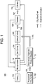
- FIG. 1 there is illustrated an exemplary embodiment of a system 100 for the prevention of esophageal fistula during intra-cardiac catheter ablation in accordance with the present invention.
- the system 100 is configured to trans-septally deliver carbon dioxide through a minimally invasive catheter to create a gaseous pocket between the posterior wall of the left atrium and the esophagus. This pocket serves to thermally isolate and separate the esophagus from the left atrium during ablation to prevent the formation of an atrial-esophageal fistula.
- the system 100 may be implemented utilizing a combination of discrete components, as a unitary, integrated system and/or a combination thereof.
- the user control 114 is configured to allow the user of the system 100, for example, a physician or electrophysiologist, to set the parameters of operation via its connection to the solenoid-controlled valve 106 and operates as part of the feed-forward path of the control loop.
- the microprocessor 112 through its feedback control process automatically adjusts and maintains the operation of the system 100 in accordance with the user's settings.
- the microprocessor 112 may comprise any suitable processor and associated software and memory to implement the operation of the system 100.
- the exemplary catheter comprises an elongate body having a proximal end and a distal end.
- the exemplary catheter 200 comprises a female luer lock connector 202 connected to a Tuohy Borst valve 204 via hypo tube 206 at the proximal valve end 208 of the Tuohy Borst valve 204.
- the carbon dioxide supply or pressurized cannister 102 illustrated in Figure 1 is connected to the injection catheter 200 via this connection point.
- unique connectors may be utilized to prevent connection to a different gas supply.
- connection point 202 may be utilized to connect any suitable means for flushing the system.
- the Tuohy Borst valve 204 also comprises a Y-connection 210.
- the Y-connection 210 may be utilized to introduce fluids for any number of purposes, including the delivery of contrast agents for fluoroscopic visualization.
- a proximal shaft 212 is connected on one end to a luer connector 214 of the Tuohy Borst valve 204 via outer shaft luer hub 216 and on the other end to a distal shaft, not illustrated.
- the Tuohy Borst valve 204, the luer connector 214 and the outer shaft hub 216 are rotationally fixed together to work as a unitary structure.
- the Tuohy Borst valve 204 facilitates transmission of torque down the catheter shaft to a fixation coil, as described in detail subsequently, to engage and advance the fixation coil into the heart wall during a procedure.
- the distal end or region of the exemplary catheter 200 is continuous with the proximal end or region described herein; however, for ease of explanation as it relates to the present invention, the description and drawings are given independently.
- This basic catheter structure may be utilized for any number of interventional procedures, including the introduction and use of an injection catheter for the delivery of carbon dioxide. A detailed description of the Tuohy Borst valve and the proximal portion of the injection catheter, and the needle assembly or distal portion of the injection catheter, as stated above, is given subsequently.
- FIG 3 is a diagrammatic representation of a Tuohy Borst valve 300.
- the Tuohy Borst valve 300 is essentially the proximal region of the injection catheter.
- the Tuohy Borst valve 300 comprises a proximal valve 302 with screw lock 304.
- the proximal valve 302 is threaded to open and close the valve.
- the screw lock 304 of the proximal valve 302 may be turned clockwise to form a liquid tight seal around any instrumentation, for example, a hypo tube, introduced therethrough to provide a pneumostatic and hemostatic seal.
- the Tuohy Borst valve 300 also comprises a threaded luer connector 306 which connects the Tuohy Borst valve 300 to the shaft luer hub 216, illustrated in Figure 2 , of the catheter as described briefly above and in greater detail subsequently.
- a deformable O-ring 308 is positioned within the proximal valve 302 such that a hypo tube 310 portion of the injection catheter passes therethrough. It is through this hypo tube 310 and ultimately a needle attached thereto that the carbon dioxide is introduced into the desired tissue.
- the hypo tube 310 is part of the catheter block 110.
- the screw lock 304 of the proximal valve 302 is tightened (clockwise for righthanded threads)
- the O-ring 308 is compressed which decreases its inside diameter. This action creates a compressive friction lock on the hypo tube 310 of the injection catheter, which may be utilized to lock the needle in place once the desired tissue depth is achieved.
- a second O-ring 312 is positioned within the threaded luer connector 306 to create a compressive seal for connection to the shaft luer hub 216, illustrated in Figure 2 .
- the hypo tube 310 comprises a stop mechanism 413.
- the stop mechanism 314 is a structure mounted around the hypo tube 310 in the region between the O-rings 308 and 312 of the Tuohy Borst valve 300. The diameter or size of the stop mechanism 314 is sufficient to prevent the hypo tube 310 from passing through either non-compressed O-ring 308, 312 to prevent accidental over-deployment of the needle into the target tissue as well as unintentional over-retraction of the injection catheter from the introducer or trans-septal sheath as described in greater detail herein.
- the hypo tube 310 may comprise any suitable biocompatible material, including any hypo tube materials currently in use in catheters.
- the stop mechanism 314 may also comprise any suitable biocompatible material.
- the stop mechanism 314 comprises a polymeric material and is bonded to the hypo tube 310 utilizing any suitable means including welding and adhesives.
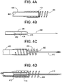
- Figures 4A - 4D are diagrammatic representations of the distal portion of an exemplary injection catheter.
- Figure 4A is a sectional or cutaway view of the distal region of an outer sheath 400 of the injection catheter.
- the outer sheath 400 comprises a tubular structure 402 in which an inner sheath 408 is coaxially positioned.
- Attached to the distal end of the outer sheath 400 is a fixation coil 404.
- the fixation coil 404 comprises a corkscrew configuration that functions as a reversible anchoring system to secure the injection catheter in place during carbon dioxide insufflation.
- the fixation coil 404 is affixed to the outer surface of the distal end of the tubular structure 402 such that a first portion thereof is sealed to the tubular structure 402 and a second portion thereof extends past the end of tubular structure for anchoring in the myocardium.
- the fixation coil 404 is permanently bonded to the tubular structure 402 by any suitable means.
- a UV curable adhesive is utilized.
- the tip of the fixation coil 404 comprises a sharp point 406, illustrated in Figure 4D , to easily pierce the cardiac tissue.
- the tubular structure 402 may comprise any suitably rigid, biocompatible material that may be navigated through a tortuous vasculature. Standard catheter materials may be utilized.
- the fixation coil 404 may comprise and suitable rigid biocompatible material that can be twisted into cardiac tissue and anchor therein. Metallic material, for example, stainless steel, or polymeric materials may be utilized. In the exemplary embodiment, the fixation coil comprises stainless steel.
- the most distal end of the outer sheath 400 also features a radiopaque marker or band 401 for fluoroscopic visualization.
- the radiopaque marker 401 may be formed from any suitable material, for example, tantalum and bonded to the outer sheath 400 utilizing any suitable means. The radiopaque marker 401 is positioned on the outer surface of the outer sheath 400 and bonded within the inside diameter of the fixation coil 404.
- the injection catheter is navigated into a position proximate the left atrium such that the fixation coil 404 may be screwed into the myocardium of the left atrium in order to maintain catheter position during carbon dioxide insufflation.
- the fixation coil 404 reversibly anchors the outer sheath 400 to the patient's heart by a simple twisting motion of the injection catheter.
- twisting or rotation of the Tuohy Borst valve 204, Figure 2 by the physician facilitates transmission of torque through the outer sheath 400.
- the needle 410 which may comprise any suitable material and be sized as set forth herein is connected to the hypo tube 310, illustrated in Figure 3 , via a plastic extrusion 412.
- the needle 410 comprises surgical steel, may comprise any other suitable metallic materials, including nitinol and highly radiopaque materials in alternate embodiments.
- the connection of the needle 410 to the plastic extrusion 412 and the connection of the plastic extrusion 412 to the hypo tube 310 may be made by any suitable means such that an unobstructed flow of carbon dioxide may be achieved while allowing the three components to act as a unitary structure.
- the needle 410 is advanced and retracted by movement of the hypo tube 310 within the outer sheath 400 which is anchored in the myocardium.
- the needle 410 and the plastic extrusion 412 are coaxially positioned within the lumen of the braided shaft forming the inner sheath 408 inside of a centering element 414.
- the needle 410 is also slidably sealed to the tip of the inner sheath 408.
- the centering element 414 and the seal 416 may be made of any suitable biocompatible material.
- Figure 4C illustrates the assembled injection catheter distal portion with the inner sheath positioned within the outer sheath 400 and the needle 410 extending therefrom.
- Figure 4D illustrates a sectional or cutaway view of the assembled injection catheter distal portion.
- the injection catheter is navigated through the vasculature and into position proximate the left atrial myocardium.
- the injection catheter is anchored into position utilizing the fixation coil 404.
- the needle 410 is advanced via the hypo tube 310 at the proximal end until the desired tissue depth is reached.
- Carbon dioxide is then injected into the fibro-fatty tissue that separates the posterior left atrium wall from the esophagus via the exemplary system illustrated in Figure 1 until the ablation procedure is completed.
- the fixation coil 404 is removed by twisting the outer sheath 400 in the opposite direction for insertion, and the injection catheter may be removed.
- the injection catheter does not in any way interfere with the left atrium ablation procedure.
- the injection catheter may be introduced via the same introducer or trans-septal sheath as the ablation catheter or a completely different one.
- the distal portion and the proximal portion of the injection catheter is shown in different illustrations for ease of explanation, the two portions form a continuous structure with inner and outer sheaths.
- the flow rate of the carbon dioxide exiting the needle may be monitored to determine the resistance to flow.
- the left atrium space, the myocardial tissue and the fibro-fatty tissue all have different resistivity to gas flow. Accordingly, the physician may simply determine in which tissue layer the needle tip resides by referencing a tissue layer flow rate characterization chart.
- the microprocessor 112 ( Figure 1 ) may be programmed with the flow resistivity of the various tissues or media in the body and receiving feedback from the flowmeter 108 as to the flow rate exiting from the needle, automatically generate an alert via some suitable signal to be displayed or an audible signal that indicates that the proper location for the needle has been achieved.
- the flowmeter may be utilized to measure the flow resistance at the needle tip and provide feedback directly to the physician or through the microprocessor 112 rather than flowmeter 108.
- the electrical activity of the tissue in which the needle is positioned may be monitored.
- the myocardium has a distinctly different electrical activity profile than the left atrium space and the surrounding tissue.
- the physician can determine the point at which the needle has contacted and subsequently passed through the myocardium and entered into the fibro-fatty tissue.
- the needle may be configured to provide feedback to a stand-alone sensing circuit or one that is part of the microprocessor.
- the sensing circuit may be configured to measure the electrical activity, for example, voltage/potential and/or resistance/impedance. As in the previously described embodiment, this information may be routed through the microprocessor 112 which will automatically make the determination or to any suitable device for altering the physician.
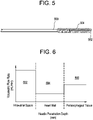
- Figure 7 is a graphical representation of voltage, or potential, vertical axis, versus needle penetration depth, horizontal axis. As illustrated, in the first region 702 corresponding to the intra-atrial space, the voltage sensed by the needle is steady-state and low. In the second region 704 corresponding to the heart wall, the electrical activity is not steady-state and at a higher potential than the first region. In the third region 706 corresponding to the periesophageal tissue, the electrical activity is once again steady-state and of lower potential than the cardiac tissue of the heart wall.
Landscapes
- Health & Medical Sciences (AREA)
- Life Sciences & Earth Sciences (AREA)
- Surgery (AREA)
- Engineering & Computer Science (AREA)
- Public Health (AREA)
- Biomedical Technology (AREA)
- Heart & Thoracic Surgery (AREA)
- Animal Behavior & Ethology (AREA)
- General Health & Medical Sciences (AREA)
- Veterinary Medicine (AREA)
- Nuclear Medicine, Radiotherapy & Molecular Imaging (AREA)
- Medical Informatics (AREA)
- Molecular Biology (AREA)
- Pathology (AREA)
- Hematology (AREA)
- Anesthesiology (AREA)
- Otolaryngology (AREA)
- Biophysics (AREA)
- Pulmonology (AREA)
- Oral & Maxillofacial Surgery (AREA)
- Plasma & Fusion (AREA)
- Physics & Mathematics (AREA)
- Dermatology (AREA)
- Cardiology (AREA)
- Surgical Instruments (AREA)
- Infusion, Injection, And Reservoir Apparatuses (AREA)
Claims (10)
- System zur Verhinderung einer Ösophagusfistel während der intrakardialen Ablation des linken Atriums, wobei das System umfasst:einen Injektionskatheter (110, 200), der einen länglichen Körper mit einem proximalen Ende und einem distalen Ende aufweist, wobei der Injektionskatheter ein Tuohy Borst-Ventil (204, 300), eine äußere Hülle (400), ein Kanülenrohr (310), das ein proximales Ende und ein distales Ende aufweist und gleitfähig in der äußeren Hülle (400) positioniert ist, eine Nadel (410), die mit dem distalen Ende des Kanülenrohrs (400) verbunden und in Fluidkommunikation damit ist, an dem distalen Ende des Injektionskatheters (110, 200), sowie eine Verankerungsvorrichtung (404), die mit der äußeren Hülle (400) verbunden ist, an dem distalen Ende des Injektionskatheters (110, 200) umfasst;eine Gaszufuhr (102), die ausgestaltet ist, um durch das Kanülenrohr (310) Gas an die Nadel (410) abzugeben, wobei die Gaszufuhr (102) mit dem proximalen Ende des Kanülenrohrs (310) verbunden ist; undein Feedback-Steuersystem, das ausgestaltet ist, um den Druck und die Flussrate des Gases von der Gaszufuhr (102) zu der Nadel (410) zu regeln, wobei das Feedback-Steuersystem umfasst:einen Druckregler (104) zum Steuern des Druckes des Gases von der Gaszufuhr (102);einen Strömungsmesser (108) zum Messen der Flussrate des Gases, das aus dem Druckregler (104) austritt und an den Injektionskatheter (110, 200) abgegeben wird;ein oder mehrere Ventile (106) zum Steuern des Gasflusses von der Gaszufuhr (102); undeinen Mikroprozessor (112) zum Steuern des Betriebs des einen oder der mehreren Ventile (106) und des Druckreglers (104) basierend auf Benutzereingabe und Feedback-Signalen von dem Strömungsmesser (108).
- System zur Verhinderung einer Ösophagusfistel während intrakardialer Ablation des linken Atriums nach Anspruch 1, wobei die Verankerungsvorrichtung (404) eine Wendelstruktur mit einem scharfen Punkt umfasst, wobei die Wendelstruktur ausgestaltet ist, um sich in Herzgewebe zu drehen, um den Injektionskatheter in Position zu sichern, wenn die äußere Hülle (400) verdreht wird.
- System zur Verhinderung einer Ösophagusfistel während intrakardialer Ablation des linken Atriums nach Anspruch 1, wobei der Injektionskatheter des Weiteren eine innere Hülle (408) umfasst, die zwischen der äußeren Hülle (400) und dem Kanülenrohr (310) positioniert ist.
- System zur Verhinderung einer Ösophagusfistel während intrakardialer Ablation des linken Atriums nach Anspruch 1, wobei das Kanülenrohr (310) einen Stoppmechanismus (314) umfasst, der an seinem proximalen Ende fixiert und ausgestaltet ist, um zu starke Ausbringung und zu starkes Zurückziehen der Nadel zu verhindern.
- System zur Verhinderung einer Ösophagusfistel während intrakardialer Ablation des linken Atriums nach Anspruch 3, wobei das Kanülenrohr (310) ausgestaltet ist, um durch die innere Hülle (408) zu gleiten, um die Nadel (410) in das Fibrofettgewebe vorzuschieben, das zwischen dem Ösophagus und dem linken Atrium liegt, um das Gas hierhin abzugeben, und um die Nadel (410) zu entfernen, wenn die Abgabe des Gases abgeschlossen ist.
- System zur Verhinderung einer Ösophagusfistel während intrakardialer Ablation des linken Atriums nach Anspruch 1, des Weiteren umfassend ein Mittel zum Bestimmen der Nadelposition.
- System zur Verhinderung einer Ösophagusfistel während intrakardialer Ablation des linken Atriums nach Anspruch 6, wobei das Mittel zum Bestimmen der Nadelposition ein Mittel zum Bestimmen der Flussrate von Gas, das aus der Nadel (410) austritt, sowie ein Mittel zum Vergleichen der gemessenen Flussraten mit dem Strömungswiderstand in verschiedenen Medien umfasst.
- System zur Verhinderung einer Ösophagusfistel während intrakardialer Ablation des linken Atriums nach Anspruch 6, wobei das Mittel zum Bestimmen der Nadelposition ein Mittel zum Messen des elektrischen Potentials an der Nadel (410) und ein Mittel zum Vergleichen des Messpotentials mit dem Potential in verschiedenen Medien umfasst.
- System zur Verhinderung einer Ösophagusfistel während intrakardialer Ablation des linken Atriums nach Anspruch 6, wobei das Mittel zum Bestimmen der Nadelposition ein Markerband umfasst, das an das Ende der äußeren Hülle montiert ist.
- System zur Verhinderung einer Ösophagusfistel während intrakardialer Ablation des linken Atriums nach Anspruch 6, wobei das Mittel zum Bestimmen der Nadelposition ein röntgendichtes Markerband umfasst, das an das Ende der äußeren Hülle (400) montiert ist.
Applications Claiming Priority (2)
| Application Number | Priority Date | Filing Date | Title |
|---|---|---|---|
| US201862631359P | 2018-02-15 | 2018-02-15 | |
| US16/127,461 US11179216B2 (en) | 2018-02-15 | 2018-09-11 | System(s), method(s) and device(s) for the prevention of esophageal fistula during catheter ablation |
Publications (2)
| Publication Number | Publication Date |
|---|---|
| EP3530220A1 EP3530220A1 (de) | 2019-08-28 |
| EP3530220B1 true EP3530220B1 (de) | 2023-01-04 |
Family
ID=65440881
Family Applications (1)
| Application Number | Title | Priority Date | Filing Date |
|---|---|---|---|
| EP19157218.9A Active EP3530220B1 (de) | 2018-02-15 | 2019-02-14 | System(e) und vorrichtung(en) zur verhinderung einer ösophagusfistel während der katheterablation |
Country Status (7)
| Country | Link |
|---|---|
| US (2) | US11179216B2 (de) |
| EP (1) | EP3530220B1 (de) |
| JP (1) | JP2019141579A (de) |
| CN (1) | CN110151299A (de) |
| AU (1) | AU2019200487A1 (de) |
| CA (1) | CA3033828A1 (de) |
| IL (1) | IL264497B (de) |
Families Citing this family (9)
| Publication number | Priority date | Publication date | Assignee | Title |
|---|---|---|---|---|
| JP7670442B2 (ja) | 2019-07-31 | 2025-04-30 | 住友重機械工業株式会社 | ショベル |
| US11672922B2 (en) * | 2019-09-26 | 2023-06-13 | Gyrus Acmi, Inc. | Distal needle and stylet tips |
| DE102019127310A1 (de) * | 2019-10-10 | 2021-04-15 | Ebnet Medical Gmbh | Fixiereinrichtung sowie Anordnung mit einem Halteelement und einer Fixiereinrichtung |
| US20210186601A1 (en) * | 2019-12-23 | 2021-06-24 | Ethicon, Inc. | Transesophageal Catheter for Thermal Protection of the Esophagus |
| US20210187242A1 (en) * | 2019-12-23 | 2021-06-24 | Ethicon, Inc. | Fluid Delivery System for Creating Separation Between Biological Surfaces |
| US20210259276A1 (en) * | 2020-02-20 | 2021-08-26 | Dsm Ip Assets B.V. | L-theanine formulation |
| WO2022076651A1 (en) * | 2020-10-08 | 2022-04-14 | University Of Pittsburgh - Of The Commonwealth System Of Higher Education | Device for measurement of core body temperature and temperature monitoring methods |
| WO2022264011A1 (en) * | 2021-06-14 | 2022-12-22 | Ethicon, Inc. | Catheter with carbon dioxide delivery system and methods |
| WO2025188826A1 (en) * | 2024-03-06 | 2025-09-12 | Edwards Lifesciences Corporation | Tissue perforation systems and handles thereof |
Family Cites Families (23)
| Publication number | Priority date | Publication date | Assignee | Title |
|---|---|---|---|---|
| US5423741A (en) * | 1993-05-28 | 1995-06-13 | Bei Medical Sytems, Inc. | Apparatus and method for the insufflation of gas into a body cavity |
| US5380292A (en) * | 1993-12-22 | 1995-01-10 | Wilson-Cook Medical, Inc. | Gastrointestinal needle mechanism |
| WO2000035531A1 (en) | 1998-12-14 | 2000-06-22 | Tre Esse Progettazione Biomedica S.R.L. | Catheter system for performing intramyocardiac therapeutic treatment |
| US6709427B1 (en) * | 1999-08-05 | 2004-03-23 | Kensey Nash Corporation | Systems and methods for delivering agents into targeted tissue of a living being |
| US6258064B1 (en) * | 1999-10-04 | 2001-07-10 | Syntheon, Llc | Helically advanceable endoscopic needle device |
| US7364567B2 (en) * | 2002-06-10 | 2008-04-29 | Abbott Cardiovascular Systems Inc. | Systems and methods for detecting tissue contact and needle penetration depth |
| AU2002952663A0 (en) * | 2002-11-14 | 2002-11-28 | Western Sydney Area Health Service | An intramural needle-tipped surgical device |
| WO2006020943A1 (en) * | 2004-08-12 | 2006-02-23 | Hansen Medical, Inc. | Robotically controlled intravascular tissue injection system |
| US7691086B2 (en) | 2005-06-14 | 2010-04-06 | Tengiz Tkebuchava | Catheter for introduction of medications to the tissues of a heart or other organ |
| US20070100355A1 (en) * | 2005-10-27 | 2007-05-03 | Medtronic, Inc. | Method and device for controlling bulking agent depth in tissue |
| US8454588B2 (en) * | 2006-03-17 | 2013-06-04 | The Board Of Trustees Of The Leland Stanford Junior University | Method and apparatus to prevent esophageal damage |
| US8900214B2 (en) | 2007-03-30 | 2014-12-02 | Onset Medical Corporation | Expandable trans-septal sheath |
| US8512387B2 (en) | 2007-09-07 | 2013-08-20 | Robert S. Fishel | Esophageal cooling system for ablation procedures associated with cardiac arrhythmias |
| US7824377B2 (en) * | 2007-12-21 | 2010-11-02 | St. Jude Medical, Atrial Fibrillation Division, Inc. | Tissue anchoring catheter systems and methods |
| US9603674B2 (en) * | 2008-05-30 | 2017-03-28 | The Regents Of The University Of California | Method to protect the esophagus and other mediastinal structures during cardiac and thoracic interventions |
| EP2665433B1 (de) * | 2011-01-19 | 2021-03-10 | Fractyl Laboratories Inc. | Vorrichtungen zur gewebebehandlung |
| US9056185B2 (en) * | 2011-08-24 | 2015-06-16 | Ablative Solutions, Inc. | Expandable catheter system for fluid injection into and deep to the wall of a blood vessel |
| TWI504922B (zh) | 2011-09-14 | 2015-10-21 | Hon Hai Prec Ind Co Ltd | 鏡頭模組 |
| JP6235559B2 (ja) | 2012-04-19 | 2017-11-22 | フラクティル ラボラトリーズ インコーポレイテッド | 組織拡張デバイス、システムおよび方法 |
| IL287605B2 (en) | 2014-03-24 | 2025-11-01 | Fractyl Health Inc | Injectate delivery devices, systems and methods |
| WO2016011269A1 (en) | 2014-07-16 | 2016-01-21 | Fractyl Laboratories, Inc. | Methods and systems for treating diabetes and related diseases and disorders |
| CH711858B1 (it) * | 2015-12-09 | 2019-10-31 | Lugano Tech Transfer Ltt Sa | Dispositivo per la rimozione di aria da una cavità anatomica in un intervento chirurgico. |
| US11045251B2 (en) | 2016-06-15 | 2021-06-29 | Steven W. Miller | Gastric tube for ablation procedures |
-
2018
- 2018-09-11 US US16/127,461 patent/US11179216B2/en not_active Expired - Fee Related
-
2019
- 2019-01-24 AU AU2019200487A patent/AU2019200487A1/en not_active Abandoned
- 2019-01-28 IL IL264497A patent/IL264497B/en unknown
- 2019-02-14 CA CA3033828A patent/CA3033828A1/en not_active Abandoned
- 2019-02-14 EP EP19157218.9A patent/EP3530220B1/de active Active
- 2019-02-14 JP JP2019024253A patent/JP2019141579A/ja active Pending
- 2019-02-15 CN CN201910116731.5A patent/CN110151299A/zh not_active Withdrawn
-
2021
- 2021-10-05 US US17/494,084 patent/US20220022993A1/en not_active Abandoned
Also Published As
| Publication number | Publication date |
|---|---|
| IL264497B (en) | 2022-03-01 |
| US20220022993A1 (en) | 2022-01-27 |
| AU2019200487A1 (en) | 2019-08-29 |
| IL264497A (en) | 2019-05-30 |
| CN110151299A (zh) | 2019-08-23 |
| JP2019141579A (ja) | 2019-08-29 |
| CA3033828A1 (en) | 2019-08-15 |
| EP3530220A1 (de) | 2019-08-28 |
| US20190247139A1 (en) | 2019-08-15 |
| US11179216B2 (en) | 2021-11-23 |
Similar Documents
| Publication | Publication Date | Title |
|---|---|---|
| US11179216B2 (en) | System(s), method(s) and device(s) for the prevention of esophageal fistula during catheter ablation | |
| US9750556B2 (en) | Cryotreatment devices and methods of forming conduction blocks | |
| JP4523586B2 (ja) | 挿入領域で隔離された領域を有する治療装置 | |
| EP2512329B1 (de) | Venenverschlussvorrichtungen für katheterbasierte ablation | |
| US9445860B2 (en) | Handheld cyrogenic treatment systems | |
| EP3698840B1 (de) | Transösophagealer katheter mit kohlendioxidabgabesystem zum thermischen schutz der speiseröhre | |
| CN105188585A (zh) | 使用温度对静脉阻塞的评定 | |
| US20190247091A1 (en) | Transesophageal Catheter With Carbon Dioxide Delivery System For Thermal Protection Of Esophagus | |
| US20210186642A1 (en) | Esophageal Protection Pathways | |
| US20210187242A1 (en) | Fluid Delivery System for Creating Separation Between Biological Surfaces | |
| US20210186601A1 (en) | Transesophageal Catheter for Thermal Protection of the Esophagus | |
| US20220395648A1 (en) | Catheter with carbon dioxide delivery system and methods | |
| WO2022264011A1 (en) | Catheter with carbon dioxide delivery system and methods | |
| HK40078506A (en) | Transesophageal catheter for thermal protection of the esophagus |
Legal Events
| Date | Code | Title | Description |
|---|---|---|---|
| PUAI | Public reference made under article 153(3) epc to a published international application that has entered the european phase |
Free format text: ORIGINAL CODE: 0009012 |
|
| STAA | Information on the status of an ep patent application or granted ep patent |
Free format text: STATUS: THE APPLICATION HAS BEEN PUBLISHED |
|
| AK | Designated contracting states |
Kind code of ref document: A1 Designated state(s): AL AT BE BG CH CY CZ DE DK EE ES FI FR GB GR HR HU IE IS IT LI LT LU LV MC MK MT NL NO PL PT RO RS SE SI SK SM TR |
|
| AX | Request for extension of the european patent |
Extension state: BA ME |
|
| STAA | Information on the status of an ep patent application or granted ep patent |
Free format text: STATUS: REQUEST FOR EXAMINATION WAS MADE |
|
| 17P | Request for examination filed |
Effective date: 20200210 |
|
| RBV | Designated contracting states (corrected) |
Designated state(s): AL AT BE BG CH CY CZ DE DK EE ES FI FR GB GR HR HU IE IS IT LI LT LU LV MC MK MT NL NO PL PT RO RS SE SI SK SM TR |
|
| GRAP | Despatch of communication of intention to grant a patent |
Free format text: ORIGINAL CODE: EPIDOSNIGR1 |
|
| STAA | Information on the status of an ep patent application or granted ep patent |
Free format text: STATUS: GRANT OF PATENT IS INTENDED |
|
| RIC1 | Information provided on ipc code assigned before grant |
Ipc: A61B 90/00 20160101ALN20220916BHEP Ipc: A61M 25/00 20060101ALN20220916BHEP Ipc: A61M 13/00 20060101ALN20220916BHEP Ipc: A61B 18/14 20060101ALN20220916BHEP Ipc: A61B 18/00 20060101ALN20220916BHEP Ipc: A61B 17/00 20060101ALN20220916BHEP Ipc: A61B 17/34 20060101AFI20220916BHEP |
|
| INTG | Intention to grant announced |
Effective date: 20221005 |
|
| GRAS | Grant fee paid |
Free format text: ORIGINAL CODE: EPIDOSNIGR3 |
|
| GRAA | (expected) grant |
Free format text: ORIGINAL CODE: 0009210 |
|
| STAA | Information on the status of an ep patent application or granted ep patent |
Free format text: STATUS: THE PATENT HAS BEEN GRANTED |
|
| AK | Designated contracting states |
Kind code of ref document: B1 Designated state(s): AL AT BE BG CH CY CZ DE DK EE ES FI FR GB GR HR HU IE IS IT LI LT LU LV MC MK MT NL NO PL PT RO RS SE SI SK SM TR |
|
| REG | Reference to a national code |
Ref country code: GB Ref legal event code: FG4D |
|
| REG | Reference to a national code |
Ref country code: DE Ref legal event code: R096 Ref document number: 602019023846 Country of ref document: DE |
|
| REG | Reference to a national code |
Ref country code: CH Ref legal event code: EP |
|
| REG | Reference to a national code |
Ref country code: AT Ref legal event code: REF Ref document number: 1541407 Country of ref document: AT Kind code of ref document: T Effective date: 20230115 |
|
| REG | Reference to a national code |
Ref country code: IE Ref legal event code: FG4D |
|
| REG | Reference to a national code |
Ref country code: LT Ref legal event code: MG9D |
|
| PGFP | Annual fee paid to national office [announced via postgrant information from national office to epo] |
Ref country code: FR Payment date: 20230110 Year of fee payment: 5 |
|
| REG | Reference to a national code |
Ref country code: NL Ref legal event code: MP Effective date: 20230104 |
|
| PGFP | Annual fee paid to national office [announced via postgrant information from national office to epo] |
Ref country code: IT Payment date: 20230224 Year of fee payment: 5 Ref country code: GB Payment date: 20230118 Year of fee payment: 5 Ref country code: DE Payment date: 20221229 Year of fee payment: 5 |
|
| REG | Reference to a national code |
Ref country code: AT Ref legal event code: MK05 Ref document number: 1541407 Country of ref document: AT Kind code of ref document: T Effective date: 20230104 |
|
| PG25 | Lapsed in a contracting state [announced via postgrant information from national office to epo] |
Ref country code: NL Free format text: LAPSE BECAUSE OF FAILURE TO SUBMIT A TRANSLATION OF THE DESCRIPTION OR TO PAY THE FEE WITHIN THE PRESCRIBED TIME-LIMIT Effective date: 20230104 |
|
| PG25 | Lapsed in a contracting state [announced via postgrant information from national office to epo] |
Ref country code: RS Free format text: LAPSE BECAUSE OF FAILURE TO SUBMIT A TRANSLATION OF THE DESCRIPTION OR TO PAY THE FEE WITHIN THE PRESCRIBED TIME-LIMIT Effective date: 20230104 Ref country code: PT Free format text: LAPSE BECAUSE OF FAILURE TO SUBMIT A TRANSLATION OF THE DESCRIPTION OR TO PAY THE FEE WITHIN THE PRESCRIBED TIME-LIMIT Effective date: 20230504 Ref country code: NO Free format text: LAPSE BECAUSE OF FAILURE TO SUBMIT A TRANSLATION OF THE DESCRIPTION OR TO PAY THE FEE WITHIN THE PRESCRIBED TIME-LIMIT Effective date: 20230404 Ref country code: LV Free format text: LAPSE BECAUSE OF FAILURE TO SUBMIT A TRANSLATION OF THE DESCRIPTION OR TO PAY THE FEE WITHIN THE PRESCRIBED TIME-LIMIT Effective date: 20230104 Ref country code: LT Free format text: LAPSE BECAUSE OF FAILURE TO SUBMIT A TRANSLATION OF THE DESCRIPTION OR TO PAY THE FEE WITHIN THE PRESCRIBED TIME-LIMIT Effective date: 20230104 Ref country code: HR Free format text: LAPSE BECAUSE OF FAILURE TO SUBMIT A TRANSLATION OF THE DESCRIPTION OR TO PAY THE FEE WITHIN THE PRESCRIBED TIME-LIMIT Effective date: 20230104 Ref country code: ES Free format text: LAPSE BECAUSE OF FAILURE TO SUBMIT A TRANSLATION OF THE DESCRIPTION OR TO PAY THE FEE WITHIN THE PRESCRIBED TIME-LIMIT Effective date: 20230104 Ref country code: AT Free format text: LAPSE BECAUSE OF FAILURE TO SUBMIT A TRANSLATION OF THE DESCRIPTION OR TO PAY THE FEE WITHIN THE PRESCRIBED TIME-LIMIT Effective date: 20230104 |
|
| PG25 | Lapsed in a contracting state [announced via postgrant information from national office to epo] |
Ref country code: SE Free format text: LAPSE BECAUSE OF FAILURE TO SUBMIT A TRANSLATION OF THE DESCRIPTION OR TO PAY THE FEE WITHIN THE PRESCRIBED TIME-LIMIT Effective date: 20230104 Ref country code: PL Free format text: LAPSE BECAUSE OF FAILURE TO SUBMIT A TRANSLATION OF THE DESCRIPTION OR TO PAY THE FEE WITHIN THE PRESCRIBED TIME-LIMIT Effective date: 20230104 Ref country code: IS Free format text: LAPSE BECAUSE OF FAILURE TO SUBMIT A TRANSLATION OF THE DESCRIPTION OR TO PAY THE FEE WITHIN THE PRESCRIBED TIME-LIMIT Effective date: 20230504 Ref country code: GR Free format text: LAPSE BECAUSE OF FAILURE TO SUBMIT A TRANSLATION OF THE DESCRIPTION OR TO PAY THE FEE WITHIN THE PRESCRIBED TIME-LIMIT Effective date: 20230405 Ref country code: FI Free format text: LAPSE BECAUSE OF FAILURE TO SUBMIT A TRANSLATION OF THE DESCRIPTION OR TO PAY THE FEE WITHIN THE PRESCRIBED TIME-LIMIT Effective date: 20230104 |
|
| REG | Reference to a national code |
Ref country code: CH Ref legal event code: PL |
|
| REG | Reference to a national code |
Ref country code: DE Ref legal event code: R097 Ref document number: 602019023846 Country of ref document: DE |
|
| REG | Reference to a national code |
Ref country code: BE Ref legal event code: MM Effective date: 20230228 |
|
| PG25 | Lapsed in a contracting state [announced via postgrant information from national office to epo] |
Ref country code: SM Free format text: LAPSE BECAUSE OF FAILURE TO SUBMIT A TRANSLATION OF THE DESCRIPTION OR TO PAY THE FEE WITHIN THE PRESCRIBED TIME-LIMIT Effective date: 20230104 Ref country code: RO Free format text: LAPSE BECAUSE OF FAILURE TO SUBMIT A TRANSLATION OF THE DESCRIPTION OR TO PAY THE FEE WITHIN THE PRESCRIBED TIME-LIMIT Effective date: 20230104 Ref country code: MC Free format text: LAPSE BECAUSE OF FAILURE TO SUBMIT A TRANSLATION OF THE DESCRIPTION OR TO PAY THE FEE WITHIN THE PRESCRIBED TIME-LIMIT Effective date: 20230104 Ref country code: LU Free format text: LAPSE BECAUSE OF NON-PAYMENT OF DUE FEES Effective date: 20230214 Ref country code: LI Free format text: LAPSE BECAUSE OF NON-PAYMENT OF DUE FEES Effective date: 20230228 Ref country code: EE Free format text: LAPSE BECAUSE OF FAILURE TO SUBMIT A TRANSLATION OF THE DESCRIPTION OR TO PAY THE FEE WITHIN THE PRESCRIBED TIME-LIMIT Effective date: 20230104 Ref country code: DK Free format text: LAPSE BECAUSE OF FAILURE TO SUBMIT A TRANSLATION OF THE DESCRIPTION OR TO PAY THE FEE WITHIN THE PRESCRIBED TIME-LIMIT Effective date: 20230104 Ref country code: CZ Free format text: LAPSE BECAUSE OF FAILURE TO SUBMIT A TRANSLATION OF THE DESCRIPTION OR TO PAY THE FEE WITHIN THE PRESCRIBED TIME-LIMIT Effective date: 20230104 Ref country code: CH Free format text: LAPSE BECAUSE OF NON-PAYMENT OF DUE FEES Effective date: 20230228 |
|
| PLBE | No opposition filed within time limit |
Free format text: ORIGINAL CODE: 0009261 |
|
| STAA | Information on the status of an ep patent application or granted ep patent |
Free format text: STATUS: NO OPPOSITION FILED WITHIN TIME LIMIT |
|
| PG25 | Lapsed in a contracting state [announced via postgrant information from national office to epo] |
Ref country code: SK Free format text: LAPSE BECAUSE OF FAILURE TO SUBMIT A TRANSLATION OF THE DESCRIPTION OR TO PAY THE FEE WITHIN THE PRESCRIBED TIME-LIMIT Effective date: 20230104 |
|
| 26N | No opposition filed |
Effective date: 20231005 |
|
| REG | Reference to a national code |
Ref country code: IE Ref legal event code: MM4A |
|
| PG25 | Lapsed in a contracting state [announced via postgrant information from national office to epo] |
Ref country code: SI Free format text: LAPSE BECAUSE OF FAILURE TO SUBMIT A TRANSLATION OF THE DESCRIPTION OR TO PAY THE FEE WITHIN THE PRESCRIBED TIME-LIMIT Effective date: 20230104 Ref country code: IE Free format text: LAPSE BECAUSE OF NON-PAYMENT OF DUE FEES Effective date: 20230214 |
|
| PG25 | Lapsed in a contracting state [announced via postgrant information from national office to epo] |
Ref country code: BE Free format text: LAPSE BECAUSE OF NON-PAYMENT OF DUE FEES Effective date: 20230228 |
|
| REG | Reference to a national code |
Ref country code: DE Ref legal event code: R119 Ref document number: 602019023846 Country of ref document: DE |
|
| GBPC | Gb: european patent ceased through non-payment of renewal fee |
Effective date: 20240214 |
|
| PG25 | Lapsed in a contracting state [announced via postgrant information from national office to epo] |
Ref country code: BG Free format text: LAPSE BECAUSE OF FAILURE TO SUBMIT A TRANSLATION OF THE DESCRIPTION OR TO PAY THE FEE WITHIN THE PRESCRIBED TIME-LIMIT Effective date: 20230104 |
|
| PG25 | Lapsed in a contracting state [announced via postgrant information from national office to epo] |
Ref country code: BG Free format text: LAPSE BECAUSE OF FAILURE TO SUBMIT A TRANSLATION OF THE DESCRIPTION OR TO PAY THE FEE WITHIN THE PRESCRIBED TIME-LIMIT Effective date: 20230104 |
|
| PG25 | Lapsed in a contracting state [announced via postgrant information from national office to epo] |
Ref country code: DE Free format text: LAPSE BECAUSE OF NON-PAYMENT OF DUE FEES Effective date: 20240903 |
|
| PG25 | Lapsed in a contracting state [announced via postgrant information from national office to epo] |
Ref country code: GB Free format text: LAPSE BECAUSE OF NON-PAYMENT OF DUE FEES Effective date: 20240214 |
|
| PG25 | Lapsed in a contracting state [announced via postgrant information from national office to epo] |
Ref country code: FR Free format text: LAPSE BECAUSE OF NON-PAYMENT OF DUE FEES Effective date: 20240229 |
|
| PG25 | Lapsed in a contracting state [announced via postgrant information from national office to epo] |
Ref country code: GB Free format text: LAPSE BECAUSE OF NON-PAYMENT OF DUE FEES Effective date: 20240214 Ref country code: FR Free format text: LAPSE BECAUSE OF NON-PAYMENT OF DUE FEES Effective date: 20240229 Ref country code: DE Free format text: LAPSE BECAUSE OF NON-PAYMENT OF DUE FEES Effective date: 20240903 |
|
| PG25 | Lapsed in a contracting state [announced via postgrant information from national office to epo] |
Ref country code: IT Free format text: LAPSE BECAUSE OF NON-PAYMENT OF DUE FEES Effective date: 20240214 |
|
| PG25 | Lapsed in a contracting state [announced via postgrant information from national office to epo] |
Ref country code: CY Free format text: LAPSE BECAUSE OF FAILURE TO SUBMIT A TRANSLATION OF THE DESCRIPTION OR TO PAY THE FEE WITHIN THE PRESCRIBED TIME-LIMIT; INVALID AB INITIO Effective date: 20190214 |
|
| PG25 | Lapsed in a contracting state [announced via postgrant information from national office to epo] |
Ref country code: HU Free format text: LAPSE BECAUSE OF FAILURE TO SUBMIT A TRANSLATION OF THE DESCRIPTION OR TO PAY THE FEE WITHIN THE PRESCRIBED TIME-LIMIT; INVALID AB INITIO Effective date: 20190214 |
|
| PG25 | Lapsed in a contracting state [announced via postgrant information from national office to epo] |
Ref country code: TR Free format text: LAPSE BECAUSE OF FAILURE TO SUBMIT A TRANSLATION OF THE DESCRIPTION OR TO PAY THE FEE WITHIN THE PRESCRIBED TIME-LIMIT Effective date: 20230104 |