EP3530214A1 - Powered stapler having varying staple heights and sizes - Google Patents
Powered stapler having varying staple heights and sizes Download PDFInfo
- Publication number
- EP3530214A1 EP3530214A1 EP19159772.3A EP19159772A EP3530214A1 EP 3530214 A1 EP3530214 A1 EP 3530214A1 EP 19159772 A EP19159772 A EP 19159772A EP 3530214 A1 EP3530214 A1 EP 3530214A1
- Authority
- EP
- European Patent Office
- Prior art keywords
- tissue contacting
- contacting surface
- tissue
- assembly
- staples
- Prior art date
- Legal status (The legal status is an assumption and is not a legal conclusion. Google has not performed a legal analysis and makes no representation as to the accuracy of the status listed.)
- Withdrawn
Links
Images

Classifications
-
- A—HUMAN NECESSITIES
- A61—MEDICAL OR VETERINARY SCIENCE; HYGIENE
- A61B—DIAGNOSIS; SURGERY; IDENTIFICATION
- A61B17/00—Surgical instruments, devices or methods
- A61B17/068—Surgical staplers, e.g. containing multiple staples or clamps
- A61B17/072—Surgical staplers, e.g. containing multiple staples or clamps for applying a row of staples in a single action, e.g. the staples being applied simultaneously
- A61B17/07207—Surgical staplers, e.g. containing multiple staples or clamps for applying a row of staples in a single action, e.g. the staples being applied simultaneously the staples being applied sequentially
-
- A—HUMAN NECESSITIES
- A61—MEDICAL OR VETERINARY SCIENCE; HYGIENE
- A61B—DIAGNOSIS; SURGERY; IDENTIFICATION
- A61B17/00—Surgical instruments, devices or methods
- A61B17/11—Surgical instruments, devices or methods for performing anastomosis; Buttons for anastomosis
- A61B17/115—Staplers for performing anastomosis, e.g. in a single operation
-
- A—HUMAN NECESSITIES
- A61—MEDICAL OR VETERINARY SCIENCE; HYGIENE
- A61B—DIAGNOSIS; SURGERY; IDENTIFICATION
- A61B17/00—Surgical instruments, devices or methods
- A61B2017/00367—Details of actuation of instruments, e.g. relations between pushing buttons, or the like, and activation of the tool, working tip, or the like
- A61B2017/00398—Details of actuation of instruments, e.g. relations between pushing buttons, or the like, and activation of the tool, working tip, or the like using powered actuators, e.g. stepper motors, solenoids
-
- A—HUMAN NECESSITIES
- A61—MEDICAL OR VETERINARY SCIENCE; HYGIENE
- A61B—DIAGNOSIS; SURGERY; IDENTIFICATION
- A61B17/00—Surgical instruments, devices or methods
- A61B2017/0046—Surgical instruments, devices or methods with a releasable handle; with handle and operating part separable
-
- A—HUMAN NECESSITIES
- A61—MEDICAL OR VETERINARY SCIENCE; HYGIENE
- A61B—DIAGNOSIS; SURGERY; IDENTIFICATION
- A61B17/00—Surgical instruments, devices or methods
- A61B2017/0046—Surgical instruments, devices or methods with a releasable handle; with handle and operating part separable
- A61B2017/00473—Distal part, e.g. tip or head
-
- A—HUMAN NECESSITIES
- A61—MEDICAL OR VETERINARY SCIENCE; HYGIENE
- A61B—DIAGNOSIS; SURGERY; IDENTIFICATION
- A61B17/00—Surgical instruments, devices or methods
- A61B2017/00477—Coupling
-
- A—HUMAN NECESSITIES
- A61—MEDICAL OR VETERINARY SCIENCE; HYGIENE
- A61B—DIAGNOSIS; SURGERY; IDENTIFICATION
- A61B17/00—Surgical instruments, devices or methods
- A61B17/068—Surgical staplers, e.g. containing multiple staples or clamps
- A61B17/072—Surgical staplers, e.g. containing multiple staples or clamps for applying a row of staples in a single action, e.g. the staples being applied simultaneously
- A61B2017/07214—Stapler heads
- A61B2017/07228—Arrangement of the staples
-
- A—HUMAN NECESSITIES
- A61—MEDICAL OR VETERINARY SCIENCE; HYGIENE
- A61B—DIAGNOSIS; SURGERY; IDENTIFICATION
- A61B17/00—Surgical instruments, devices or methods
- A61B17/068—Surgical staplers, e.g. containing multiple staples or clamps
- A61B17/072—Surgical staplers, e.g. containing multiple staples or clamps for applying a row of staples in a single action, e.g. the staples being applied simultaneously
- A61B2017/07214—Stapler heads
- A61B2017/07235—Stapler heads containing different staples, e.g. staples of different shapes, sizes or materials
-
- A—HUMAN NECESSITIES
- A61—MEDICAL OR VETERINARY SCIENCE; HYGIENE
- A61B—DIAGNOSIS; SURGERY; IDENTIFICATION
- A61B17/00—Surgical instruments, devices or methods
- A61B17/068—Surgical staplers, e.g. containing multiple staples or clamps
- A61B17/072—Surgical staplers, e.g. containing multiple staples or clamps for applying a row of staples in a single action, e.g. the staples being applied simultaneously
- A61B2017/07214—Stapler heads
- A61B2017/07242—Stapler heads achieving different staple heights during the same shot, e.g. using an anvil anvil having different heights or staples of different sizes
-
- A—HUMAN NECESSITIES
- A61—MEDICAL OR VETERINARY SCIENCE; HYGIENE
- A61B—DIAGNOSIS; SURGERY; IDENTIFICATION
- A61B17/00—Surgical instruments, devices or methods
- A61B17/068—Surgical staplers, e.g. containing multiple staples or clamps
- A61B17/072—Surgical staplers, e.g. containing multiple staples or clamps for applying a row of staples in a single action, e.g. the staples being applied simultaneously
- A61B2017/07214—Stapler heads
- A61B2017/07257—Stapler heads characterised by its anvil
-
- A—HUMAN NECESSITIES
- A61—MEDICAL OR VETERINARY SCIENCE; HYGIENE
- A61B—DIAGNOSIS; SURGERY; IDENTIFICATION
- A61B17/00—Surgical instruments, devices or methods
- A61B17/068—Surgical staplers, e.g. containing multiple staples or clamps
- A61B17/072—Surgical staplers, e.g. containing multiple staples or clamps for applying a row of staples in a single action, e.g. the staples being applied simultaneously
- A61B2017/07214—Stapler heads
- A61B2017/07271—Stapler heads characterised by its cartridge
-
- A—HUMAN NECESSITIES
- A61—MEDICAL OR VETERINARY SCIENCE; HYGIENE
- A61B—DIAGNOSIS; SURGERY; IDENTIFICATION
- A61B17/00—Surgical instruments, devices or methods
- A61B17/068—Surgical staplers, e.g. containing multiple staples or clamps
- A61B17/072—Surgical staplers, e.g. containing multiple staples or clamps for applying a row of staples in a single action, e.g. the staples being applied simultaneously
- A61B2017/07214—Stapler heads
- A61B2017/07285—Stapler heads characterised by its cutter
Definitions
- the present disclosure relates to surgical stapling instruments and, more particularly, to powered surgical stapling instruments including a loading unit configured to provide a variable pressure gradient to layers of tissue clamped between anvil and cartridge assemblies of the loading unit.
- surgical stapling instruments specifically adapted for use in various procedures such as end-to-end anastomosis, gastrointestinal anastomosis, endoscopic gastrointestinal anastomosis, and transverse anastomosis.
- These surgical stapling instruments typically include a cartridge assembly and an anvil assembly.
- the cartridge assembly has one or more laterally spaced rows of staples which, depending on the particular stapling instrument, may be arranged in a linear or non-linear configuration.
- the anvil assembly includes staple forming depressions which are aligned with and/or in registration with the staple slots in the cartridge assembly.
- each of the surgical stapling instruments involves gripping of tissue to be fastened, ejecting individual staples from the cartridge assembly through the gripped tissue, and forming the staples against the staple forming depressions of the anvil assembly.
- the present disclosure is directed towards powered surgical stapling instruments configured to effectuate an improved balance between the anastomotic strength and the degree of hemostasis at the tissue interface.
- a powered surgical stapling instrument in accordance with an embodiment of the present disclosure.
- the powered surgical stapling instrument includes a powered handle assembly, a powered adapter assembly releasably secured to the powered handle assembly, and a loading unit releasably secured to the powered adapter assembly.
- the loading unit includes an anvil assembly and a cartridge assembly movable relative to the anvil assembly between open and approximated positions.
- the anvil assembly includes a first tissue contacting surface.
- the cartridge assembly includes a second tissue contacting surface, a first plurality of staples, a second plurality of staples, and a plurality of pushers.
- the second tissue contacting surface defines a knife channel partitioning the second tissue contacting surface into first and second portions.
- the second tissue contacting surface is stepped.
- Each of the first and second portions includes an inner tissue contacting surface and an outer tissue contacting surface.
- the inner tissue contacting surface is disposed adjacent the knife channel.
- the inner tissue contacting surface defines a first row of retention slots.
- the inner tissue contacting surface and the first tissue contacting surface of the anvil assembly define a first tissue gap.
- the outer tissue contacting surface is disposed laterally outward of the respective inner tissue contacting surface and defines a second row of retention slots.
- the outer tissue contacting surface and the first tissue contacting surface of the anvil assembly define a second tissue gap larger than the first tissue gap.
- the first plurality of staples has a first unformed leg length.
- the first plurality of staples is disposed in the first row of retention slots.
- the second plurality of staples has a second unformed leg length longer than the first unformed leg length.
- the second plurality of staples is disposed in the second row of retention slots.
- Each pusher of the plurality of pushers includes first and second panels configured to eject respective one of the first plurality of staples and one of the second plurality of staples through the second tissue contacting surface of the cartridge assembly.
- the first row of retention slots of the inner tissue contacting surface may be axially offset from the second row of retention slots of the outer tissue contacting surface.
- the first panel may have a height longer than the second panel.
- each pusher of the plurality of pushers may further include a base panel interconnecting the first and second panels.
- each of the first and second portions of the second tissue contacting surface of the cartridge assembly may include a transitioning portion interconnecting the respective inner and outer tissue contacting surfaces.
- the transitioning portion may define a slope configured to provide gradual compression on tissue when tissue is clamped between the anvil assembly and the cartridge assembly.
- the first tissue contacting surface of the anvil assembly may be planar.
- the first tissue contacting surface of the anvil assembly may define a longitudinal channel in registration with the knife channel of the cartridge assembly.
- the inner and outer tissue contacting surfaces of the first and second portions of the second tissue contacting surface of the cartridge assembly may be symmetric with respect to the knife channel of the cartridge assembly.
- the inner tissue contacting surfaces of the first and second portions of the second tissue contacting surface of the cartridge assembly may be coplanar.
- the outer tissue contacting surfaces of the first and second portions of the second tissue contacting surface of the cartridge assembly may be coplanar.
- the outer tissue contacting surfaces may be parallel to the inner tissue contacting surfaces.
- the second tissue contacting surface of the cartridge assembly and the first tissue contacting surfaces of the anvil assembly may define a varying tissue gap and may be configured to apply pressure to tissue disposed therebetween, wherein an amount of pressure applied to a portion of tissue disposed on the inner tissue contacting surface of the cartridge assembly is greater than an amount of pressure applied to a second portion of tissue disposed on the outer tissue contacting surface of the cartridge assembly.
- a powered surgical stapling instrument including a powered handle assembly, a powered adapter assembly releasably secured to the powered handle assembly, and a loading unit releasably secured to the powered adapter assembly.
- the loading unit including an anvil assembly and a cartridge assembly.
- the anvil assembly includes a planar anvil surface defining a plurality of staple-forming depressions. At least one of the anvil assembly or the cartridge assembly is movable relative to the other between an open position and a pre-fire position.
- the cartridge assembly includes a tissue contacting surface, a first plurality of unformed staples, and a second plurality of unformed staples.
- the tissue contacting surface defines a knife channel partitioning the tissue contacting surface into first and second portions.
- the tissue contacting surface is stepped.
- Each of the first and second portions includes a first tissue contacting surface and a second tissue contacting surface.
- the first tissue contacting surface includes a first plurality of staple retention slots.
- the first tissue contacting surface and the planar anvil surface are configured to apply a first pressure to tissue disposed therebetween in the pre-fire position.
- the second tissue contacting surface defines a second plurality of staple retention slots.
- the second tissue contacting surface and the planar anvil surface are configured to apply a second pressure to tissue disposed therebetween in the pre-fire position.
- the second pressure is less than the first pressure.
- the first plurality of unformed staples has a first leg length.
- the first plurality of unformed staples is configured to be ejected through the first plurality of staple retention slots and into engagement with the plurality of staple-forming depressions of the anvil assembly to form a first plurality of formed staples.
- the second plurality of unformed staples has a second leg length.
- the second plurality of unformed staples is configured to be ejected through the second plurality of staple retention slots and into engagement with the plurality of staple-forming depressions of the anvil assembly to form a second plurality of formed staples.
- the second leg length is longer than the first leg length.
- distal as is conventional, will refer to that portion of the instrument, apparatus, device or component thereof which is farther from the user while, the term “proximal,” will refer to that portion of the instrument, apparatus, device or component thereof which is closer to the user.
- proximal will refer to that portion of the instrument, apparatus, device or component thereof which is closer to the user.
- a powered surgical stapler in accordance with embodiments of the present disclosure is generally shown as a surgical stapler 10.
- Surgical stapler 10 includes a powered handle assembly 12, a powered adapter assembly 14 releasably secured to powered handle assembly 12, and a loading unit 100 releasably secured to powered adapter assembly 14.
- U.S. Patent No. 9,055,943 (“the '943 Patent")
- U.S. Patent Application Publication No. 2016/0106406 the entire contents of each of which is incorporated herein by reference, for a detailed discussion of the construction and operation of exemplary powered handle and adapter assemblies.
- the device may be manually operated.
- U.S. Patent Application Publication No. 2013/0098965 the entire contents of which is incorporated herein by reference, for a detailed discussion of the construction and operation of exemplary manually operated handle assemblies.
- loading unit 100 of surgical stapler 10 includes a body portion 102 and a tool assembly 104.
- Body portion 102 is configured to be releasably coupled to powered adapter assembly 14 ( FIG. 1 ).
- Tool assembly 104 includes an anvil assembly 140 and a cartridge assembly 150 that is movable in relation to anvil assembly 140 between open and approximated positions.
- a mounting assembly 106 is provided to couple tool assembly 104 to body portion 102 of loading unit 100.
- mounting assembly 106 couples tool assembly 104 to body portion 102 to facilitate pivotal movement of tool assembly 104 about an axis "T-T" transverse to a longitudinal axis "X-X" of body portion 102.
- anvil assembly 140 includes an anvil body 142 and an anvil plate 144 secured to the underside of anvil body 142.
- anvil plate 144 includes a planar tissue contacting surface 144a that defines linear rows of staple forming depressions 144b.
- tissue contacting surface 144a of anvil plate 144 may be stepped or curved.
- Anvil assembly 140 may define a longitudinal slot 145 configured to receive a knife blade 157 ( FIG. 7 ) therethrough.
- cartridge assembly 150 includes a cartridge body 154 and a staple cartridge 152 that may be removably received in cartridge body 154.
- Staple cartridge 152 includes a tissue contacting surface 161 configured to receive tissue thereon and defines a knife channel 155 configured to slidably receive a knife blade 157 ( FIG. 7 ) and a drive beam (not shown).
- Knife channel 155 extends through tissue contacting surface 161 of staple cartridge 152 such that tissue contacting surface 161 is partitioned into first and second portions 161a, 161b.
- First and second portions 161a, 161b of tissue contacting surface 161 include respective inner tissue contacting surfaces 163a, 163b disposed adjacent knife channel 155, and outer tissue contacting surfaces 165a, 165b disposed laterally outward from the respective inner tissue contacting surfaces 163a, 163b.
- inner tissue contacting surfaces 163a, 163b are coplanar
- outer tissue contacting surfaces 165a, 165b are coplanar.
- Knife channel 155 may be centered on tissue contacting surface 161 such that inner and outer tissue contacting surfaces 163a, 163b, 165a, 165b on respective first and second portions 161a, 161b are symmetric with respect to knife channel 155.
- tissue contacting surface 144a of anvil assembly 140 and inner tissue contacting surfaces 163a, 163b of cartridge assembly 150 define a first tissue gap G 1 ( FIG. 7 ), and tissue contacting surface 144a of anvil assembly 140 and outer tissue contacting surfaces 165a, 165b of cartridge assembly 150 define a second tissue gap G 2 ( FIG. 7 ) larger than first tissue gap G 1 .
- tissue contacting surface 161 of staple cartridge 152 further includes transition portions 167a, 167b that interconnect the respective inner tissue contacting surfaces 163a, 163b and outer tissue contacting surfaces 165a, 165b.
- Transition portions 167a, 167b are sloped to provide gradual transition of compression force on tissue when tissue is clamped between anvil assembly 140 and cartridge assembly 150.
- transition portions 167a, 167a direct fluid within tissue to flow laterally outward away from knife channel 150 when tissue is clamped between anvil assembly 140 and cartridge assembly 150.
- tissue gaps between tissue contacting surface 161 of cartridge assembly 150 and tissue contacting surface 144a of anvil assembly 140 varies the amount of pressure applied to tissue disposed between tissue contacting surface 144a and tissue contacting surface 161 along a plane that is transverse to a longitudinal axis "Y-Y" ( FIG. 5 ) of staple cartridge 152.
- staple cartridge 152 defines a plurality of staple retention slots 193a, 193b, 195a, 195b ( FIG. 6 ) extending through tissue contacting surface 161.
- Staple retention slots 193a, 193b are arranged in a linear fashion in respective inner tissue contacting surfaces 163a, 163b, and staple retention slots 195a, 195b are arranged in a linear fashion in respective outer tissue contacting surfaces 165a, 165b.
- two linear rows of staple retention slots 193a, 193b, 195a, 195b are provided on each side of knife channel 155 in first and second portions 161a, 161b of tissue contacting surface 161.
- one or more additional rows of staple retention slots may be provided on tissue contacting surface 161
- Staple retention slots 193a, 193b are axially offset from respective staple retention slots 195a, 195b. Staple retention slots 193a, 193b, 195a, 195b are in alignment with staple receiving depressions 144b ( FIG. 4 ) defined in anvil plate 144. Each staple retention slot 193a, 193b, 195a, 195b is dimensioned to receive a respective surgical staple S 1 , S 2 ( FIG. 8 ) and a portion of a pusher 164.
- Surgical staples S 1 , S 2 are supported on respective staple pushers 164 which are positioned to be engaged by a sled (not shown) such that longitudinal translation of the sled through cartridge body 154 urges pushers 164 towards the tissue contacting surface 161 of staple cartridge 152 to eject surgical staples S 1 , S 2 out of respective staple retention slots 193a, 193b, 195a, 195b.
- a sled not shown
- the closed or formed staple height is too high, then it may inadequately appose the tissues and result in leakage, bleeding, and/or dehiscence.
- the formed staple height is too low, then, e.g, ischemia or serosal shearing, may result, potentially leading to leakage or necrosis of tissue.
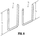
- staple retention slots 193a, 193b defined in inner tissue contacting surfaces 163a, 163b receive staple S 2 having a leg length of H2 and staple retention slots 195a, 195b defined in outer tissue contacting surfaces 165a, 165b receive staple S 1 having a leg length of H 1 longer than H 2 .
- H 1 may be about 4.1 mm and H 2 may be about 3.5 mm.
- H 1 may be about 3.5 mm and H 2 may be about 2.3 mm.
- surgical staples S 1 , S 2 may be formed of a permanent or re-absorbable polymer.
- surgical staples S 1 , S 2 may be formed of different materials. It is also contemplated that a diameter of the staple wire may vary in order to improve securement of surgical staples Si, S 2 in tissue.
- each pusher 164 includes a first panel 164a, a second panel 164b, and a base panel 164c interconnecting first and second panels 164a, 164b.
- First panel 164a is dimensioned to be received in a respective staple retention slot 193a, 193b, and second panel 164b is dimensioned to be received in a respective staple retention slot 195a, 195b.
- First panel 164a has a height larger than a height of second panel 164b to accommodate shorter surgical staples S 2 .
- tissue contacting surface 161 of staple cartridge 152 causes a greater degree of compression to occur along inner tissue contacting surface 163a, 163b of cartridge assembly 150 adjacent knife channel 155. This greater degree of compression urges fluid stored in the layers of tissue adjacent knife channel 155 to flow laterally outward from knife channel 155.
- the decrease in overall tissue thickness is such that surgical staple S 2 having a shorter leg length H2 tightly fastens the layers of tissue adjacent knife channel 155 to inhibit leakage from the fastened tissue.
- the tissue gap G 2 increases towards outer walls 159 of cartridge body 154 as the amount of compression decreases, whereby surgical staples S 1 having a longer leg length H 1 less tightly fasten the layers of tissue on outer tissue contacting surfaces 165a, 165b.
- the reduced compression and reduced tightness of the staples S 1 outwardly of inner tissue contacting surfaces 163a, 163b allows a minimal amount of blood to flow past staples S 1 towards staples S 2 to reduce the likelihood of necrosis of tissue adjacent staples S 1 .
- necrosis of tissue adjacent staples S 1 By inhibiting necrosis of tissue adjacent staples S 1 , the strength of the tissue and thus, the staple line is improved.
- the actuation mechanism is actuated for sequentially ejecting surgical staples S 1 , S 2 through respective staple retention slots 193a, 193b, 195a, 195b, whereby interaction between surgical staples S 1 , S 2 and anvil assembly 140 forms completed surgical staples for joining the layers of tissue.
- an actuation sled (not shown) is positioned within the cartridge body 154 to pass longitudinally through cartridge body 154 into sequential engagement with pushers 164 to sequentially eject staples S 1 , S 2 from cartridge body 154.
- U.S. Patent No. 6,202,914 the entire contents of which is also incorporated herein by reference, for a detailed discussion of the construction and operation of the actuation mechanism including the sled (not shown) and pushers 164.
- Tissue contacting surface 161 provides a variable pressure gradient (i.e. load profile) to tissue clamped between anvil assembly 140 and cartridge assembly 150. By providing a gradual compression gradient to the layers of tissue, a higher degree of hemostasis may be effected.
- the layers of tissue disposed on inner tissue contacting surfaces 163a, 163b are subject to higher compressive forces, which, in turn, forms thinner layers of tissue as compared to layers of tissue disposed on outer tissue contacting surfaces 165a, 165b. Since the layers of tissue on inner tissue contacting surfaces 163a, 163b can be compressed more, smaller sized surgical staple S 2 are used to staple the transected layers of tissue.
- the smaller surgical staples S 2 are disposed adjacent the cut line in the tissue.
- Surgical staples S 1 which are the larger staples, are disposed laterally outward of surgical staples S 2 . This arrangement provides improved hemostasis in the portion of tissue having surgical staples S 2 and further supports improved blood flow through tissue towards surgical staples S 2 to inhibit necrosis of tissue supporting the formed staples S 2 .
- tissue interface has a substantially tapered profile ( FIG. 10 ).
- the tissue interface has a gradual transition from the un-fastened layers of tissue to the fastened layers of tissue. This arrangement provides gradual tissue loading or compression due to the varying sizes of the formed surgical staples S 1 , S 2 , thereby minimizing tissue trauma while maintaining a relatively high degree of hemostasis and anastomotic strength.
- surgical stapler 10 may further include a dispensing tissue reinforcement material, e.g., surgical glue or bio-cement, onto tissue simultaneously with and/or immediately following stapling and cutting of tissue.
- tissue reinforcement material e.g., surgical glue or bio-cement
- the staple cartridge may have a single planar tissue contacting surface and the anvil member may be provided with tissue contacting surface varying in height so as to define more than one tissue gap with respect to the tissue contacting surface of the staple cartridge.
Landscapes
- Health & Medical Sciences (AREA)
- Life Sciences & Earth Sciences (AREA)
- Surgery (AREA)
- Heart & Thoracic Surgery (AREA)
- Engineering & Computer Science (AREA)
- Biomedical Technology (AREA)
- Nuclear Medicine, Radiotherapy & Molecular Imaging (AREA)
- Medical Informatics (AREA)
- Molecular Biology (AREA)
- Animal Behavior & Ethology (AREA)
- General Health & Medical Sciences (AREA)
- Public Health (AREA)
- Veterinary Medicine (AREA)
- Surgical Instruments (AREA)
Abstract
Description
- The present disclosure relates to surgical stapling instruments and, more particularly, to powered surgical stapling instruments including a loading unit configured to provide a variable pressure gradient to layers of tissue clamped between anvil and cartridge assemblies of the loading unit.
- There are several known types of surgical stapling instruments specifically adapted for use in various procedures such as end-to-end anastomosis, gastrointestinal anastomosis, endoscopic gastrointestinal anastomosis, and transverse anastomosis. These surgical stapling instruments typically include a cartridge assembly and an anvil assembly. The cartridge assembly has one or more laterally spaced rows of staples which, depending on the particular stapling instrument, may be arranged in a linear or non-linear configuration. The anvil assembly includes staple forming depressions which are aligned with and/or in registration with the staple slots in the cartridge assembly. In use, each of the surgical stapling instruments involves gripping of tissue to be fastened, ejecting individual staples from the cartridge assembly through the gripped tissue, and forming the staples against the staple forming depressions of the anvil assembly.
- A common issue in transecting tissue and/or in anastomosis procedures is achieving optimal balance between anastomotic strength and hemostasis. Therefore, a need exists for simple and effective powered surgical stapling instruments capable of improving the anastomotic strength and the degree of hemostasis when the layers of tissue are clamped and fastened between the anvil assembly and the cartridge assembly.
- The present disclosure is directed towards powered surgical stapling instruments configured to effectuate an improved balance between the anastomotic strength and the degree of hemostasis at the tissue interface. There is provided a powered surgical stapling instrument in accordance with an embodiment of the present disclosure. The powered surgical stapling instrument includes a powered handle assembly, a powered adapter assembly releasably secured to the powered handle assembly, and a loading unit releasably secured to the powered adapter assembly. The loading unit includes an anvil assembly and a cartridge assembly movable relative to the anvil assembly between open and approximated positions. The anvil assembly includes a first tissue contacting surface. The cartridge assembly includes a second tissue contacting surface, a first plurality of staples, a second plurality of staples, and a plurality of pushers.
- The second tissue contacting surface defines a knife channel partitioning the second tissue contacting surface into first and second portions. The second tissue contacting surface is stepped. Each of the first and second portions includes an inner tissue contacting surface and an outer tissue contacting surface. The inner tissue contacting surface is disposed adjacent the knife channel. The inner tissue contacting surface defines a first row of retention slots. The inner tissue contacting surface and the first tissue contacting surface of the anvil assembly define a first tissue gap. The outer tissue contacting surface is disposed laterally outward of the respective inner tissue contacting surface and defines a second row of retention slots. The outer tissue contacting surface and the first tissue contacting surface of the anvil assembly define a second tissue gap larger than the first tissue gap.
- The first plurality of staples has a first unformed leg length. The first plurality of staples is disposed in the first row of retention slots. The second plurality of staples has a second unformed leg length longer than the first unformed leg length. The second plurality of staples is disposed in the second row of retention slots. Each pusher of the plurality of pushers includes first and second panels configured to eject respective one of the first plurality of staples and one of the second plurality of staples through the second tissue contacting surface of the cartridge assembly.
- In an embodiment, the first row of retention slots of the inner tissue contacting surface may be axially offset from the second row of retention slots of the outer tissue contacting surface.
- In another embodiment, the first panel may have a height longer than the second panel.
- In still another embodiment, each pusher of the plurality of pushers may further include a base panel interconnecting the first and second panels.
- In still another embodiment, each of the first and second portions of the second tissue contacting surface of the cartridge assembly may include a transitioning portion interconnecting the respective inner and outer tissue contacting surfaces.
- In yet another embodiment, the transitioning portion may define a slope configured to provide gradual compression on tissue when tissue is clamped between the anvil assembly and the cartridge assembly.
- In still yet another embodiment, the first tissue contacting surface of the anvil assembly may be planar.
- In still yet another embodiment, the first tissue contacting surface of the anvil assembly may define a longitudinal channel in registration with the knife channel of the cartridge assembly.
- In still yet another embodiment, the inner and outer tissue contacting surfaces of the first and second portions of the second tissue contacting surface of the cartridge assembly may be symmetric with respect to the knife channel of the cartridge assembly.
- In still yet another embodiment, the inner tissue contacting surfaces of the first and second portions of the second tissue contacting surface of the cartridge assembly may be coplanar. In addition, the outer tissue contacting surfaces of the first and second portions of the second tissue contacting surface of the cartridge assembly may be coplanar.
- In still yet another embodiment, the outer tissue contacting surfaces may be parallel to the inner tissue contacting surfaces.
- In still yet another embodiment, the second tissue contacting surface of the cartridge assembly and the first tissue contacting surfaces of the anvil assembly may define a varying tissue gap and may be configured to apply pressure to tissue disposed therebetween, wherein an amount of pressure applied to a portion of tissue disposed on the inner tissue contacting surface of the cartridge assembly is greater than an amount of pressure applied to a second portion of tissue disposed on the outer tissue contacting surface of the cartridge assembly.
- In accordance with another embodiment of the present disclosure, there is provided a powered surgical stapling instrument including a powered handle assembly, a powered adapter assembly releasably secured to the powered handle assembly, and a loading unit releasably secured to the powered adapter assembly. The loading unit including an anvil assembly and a cartridge assembly. The anvil assembly includes a planar anvil surface defining a plurality of staple-forming depressions. At least one of the anvil assembly or the cartridge assembly is movable relative to the other between an open position and a pre-fire position. The cartridge assembly includes a tissue contacting surface, a first plurality of unformed staples, and a second plurality of unformed staples. The tissue contacting surface defines a knife channel partitioning the tissue contacting surface into first and second portions. The tissue contacting surface is stepped. Each of the first and second portions includes a first tissue contacting surface and a second tissue contacting surface. The first tissue contacting surface includes a first plurality of staple retention slots. The first tissue contacting surface and the planar anvil surface are configured to apply a first pressure to tissue disposed therebetween in the pre-fire position. The second tissue contacting surface defines a second plurality of staple retention slots. The second tissue contacting surface and the planar anvil surface are configured to apply a second pressure to tissue disposed therebetween in the pre-fire position. The second pressure is less than the first pressure. The first plurality of unformed staples has a first leg length. The first plurality of unformed staples is configured to be ejected through the first plurality of staple retention slots and into engagement with the plurality of staple-forming depressions of the anvil assembly to form a first plurality of formed staples. The second plurality of unformed staples has a second leg length. The second plurality of unformed staples is configured to be ejected through the second plurality of staple retention slots and into engagement with the plurality of staple-forming depressions of the anvil assembly to form a second plurality of formed staples. The second leg length is longer than the first leg length.
- The accompanying drawings illustrate embodiments of the disclosure and, together with a general description of the disclosure given above, and the detailed description of the embodiment(s) given below, serve to explain the principles of the disclosure, wherein:
-
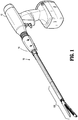
FIG. 1 is a perspective view of a powered surgical stapling instrument constructed in accordance with an exemplary embodiment of the present disclosure with a tool assembly in an open position; -
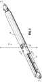
FIG. 2 is a perspective view of a loading unit of the powered surgical stapling instrument ofFIG. 1 with the tool assembly in an approximated position; -
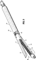
FIG. 3 is a perspective view of the loading unit of the powered surgical stapling instrument ofFIG. 1 ; -
FIG. 4 is a partial, plan view of an anvil assembly of the loading unit ofFIG. 2 ; -
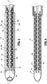
FIG. 5 is a partial, plan view of a cartridge assembly of the loading unit ofFIG. 2 ; -
FIG. 6 is an enlarged view of the indicated area detail ofFIG. 3 ; -
FIG. 7 is a cross-sectional view taken along section line 7-7 ofFIG. 2 ; -
FIG. 8 is a perspective view of staples for use with the loading unit ofFIG. 2 ; -
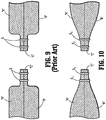
FIG. 9 is a side view of a tissue/staple interface following a firing of a conventional surgical stapling instrument; and -
FIG. 10 is a side view of a tissue/staple interface following the firing of the powered surgical stapling instrument ofFIG. 1 . - Embodiments of the present powered surgical stapling instruments will now be described in detail with reference to the drawings, in which like reference numerals designate identical or corresponding elements in each of the several views. As used herein, the term "distal," as is conventional, will refer to that portion of the instrument, apparatus, device or component thereof which is farther from the user while, the term "proximal," will refer to that portion of the instrument, apparatus, device or component thereof which is closer to the user. In the following description, well-known functions or constructions are not described in detail to avoid obscuring the present disclosure in unnecessary detail.
- With reference to
FIG. 1 , a powered surgical stapler in accordance with embodiments of the present disclosure is generally shown as asurgical stapler 10.Surgical stapler 10 includes apowered handle assembly 12, apowered adapter assembly 14 releasably secured topowered handle assembly 12, and aloading unit 100 releasably secured topowered adapter assembly 14. Reference may be made toU.S. Patent No. 9,055,943 U.S. Patent Application Publication No. 2016/0106406 , the entire contents of each of which is incorporated herein by reference, for a detailed discussion of the construction and operation of exemplary powered handle and adapter assemblies. Alternatively, the device may be manually operated. Reference may be made toU.S. Patent Application Publication No. 2013/0098965 , the entire contents of which is incorporated herein by reference, for a detailed discussion of the construction and operation of exemplary manually operated handle assemblies. - With reference now to
FIGS. 2 and3 ,loading unit 100 ofsurgical stapler 10 includes abody portion 102 and atool assembly 104.Body portion 102 is configured to be releasably coupled to powered adapter assembly 14 (FIG. 1 ).Tool assembly 104 includes ananvil assembly 140 and acartridge assembly 150 that is movable in relation toanvil assembly 140 between open and approximated positions. A mountingassembly 106 is provided to coupletool assembly 104 tobody portion 102 ofloading unit 100. In embodiments, mounting assembly 106couples tool assembly 104 tobody portion 102 to facilitate pivotal movement oftool assembly 104 about an axis "T-T" transverse to a longitudinal axis "X-X" ofbody portion 102. - With reference to
FIGS. 3 and4 ,anvil assembly 140 includes ananvil body 142 and ananvil plate 144 secured to the underside ofanvil body 142. In embodiments,anvil plate 144 includes a planartissue contacting surface 144a that defines linear rows ofstaple forming depressions 144b. Alternatively,tissue contacting surface 144a ofanvil plate 144 may be stepped or curved.Anvil assembly 140 may define alongitudinal slot 145 configured to receive a knife blade 157 (FIG. 7 ) therethrough. - With reference now to
FIGS. 5-7 ,cartridge assembly 150 includes acartridge body 154 and astaple cartridge 152 that may be removably received incartridge body 154.Staple cartridge 152 includes atissue contacting surface 161 configured to receive tissue thereon and defines aknife channel 155 configured to slidably receive a knife blade 157 (FIG. 7 ) and a drive beam (not shown).Knife channel 155 extends throughtissue contacting surface 161 ofstaple cartridge 152 such thattissue contacting surface 161 is partitioned into first andsecond portions second portions tissue contacting surface 161 include respective innertissue contacting surfaces adjacent knife channel 155, and outertissue contacting surfaces tissue contacting surfaces tissue contacting surfaces tissue contacting surfaces Knife channel 155 may be centered ontissue contacting surface 161 such that inner and outertissue contacting surfaces second portions knife channel 155. In embodiments, in the approximated position oftool assembly 104,tissue contacting surface 144a ofanvil assembly 140 and innertissue contacting surfaces cartridge assembly 150 define a first tissue gap G1 (FIG. 7 ), andtissue contacting surface 144a ofanvil assembly 140 and outertissue contacting surfaces cartridge assembly 150 define a second tissue gap G2 (FIG. 7 ) larger than first tissue gap G1. - With particular reference to
FIG. 7 ,tissue contacting surface 161 ofstaple cartridge 152 further includestransition portions tissue contacting surfaces tissue contacting surfaces Transition portions anvil assembly 140 andcartridge assembly 150. Moreover,transition portions knife channel 150 when tissue is clamped betweenanvil assembly 140 andcartridge assembly 150. - In this arrangement, varying the size of tissue gaps between
tissue contacting surface 161 ofcartridge assembly 150 andtissue contacting surface 144a ofanvil assembly 140 varies the amount of pressure applied to tissue disposed betweentissue contacting surface 144a andtissue contacting surface 161 along a plane that is transverse to a longitudinal axis "Y-Y" (FIG. 5 ) ofstaple cartridge 152. - With continued reference to
FIGS. 6 and 7 ,staple cartridge 152 defines a plurality ofstaple retention slots FIG. 6 ) extending throughtissue contacting surface 161.Staple retention slots tissue contacting surfaces staple retention slots tissue contacting surfaces staple retention slots knife channel 155 in first andsecond portions tissue contacting surface 161. While it is envisioned that one or more additional rows of staple retention slots may be provided ontissue contacting surface 161, by providing two linear rows ofstaple retention slots knife channel 155, the dimensions ofcartridge assembly 150 andanvil assembly 140 are minimized to facilitate insertion ofloading unit 100 through a small diameter incision or cannula and reduce patient trauma. -
Staple retention slots staple retention slots Staple retention slots staple receiving depressions 144b (FIG. 4 ) defined inanvil plate 144. Eachstaple retention slot FIG. 8 ) and a portion of apusher 164. Surgical staples S1, S2 are supported on respectivestaple pushers 164 which are positioned to be engaged by a sled (not shown) such that longitudinal translation of the sled throughcartridge body 154 urgespushers 164 towards thetissue contacting surface 161 ofstaple cartridge 152 to eject surgical staples S1, S2 out of respectivestaple retention slots U.S. Patent Application Publication No. 2013/0098965 . If the closed or formed staple height is too high, then it may inadequately appose the tissues and result in leakage, bleeding, and/or dehiscence. Conversely, if the formed staple height is too low, then, e.g, ischemia or serosal shearing, may result, potentially leading to leakage or necrosis of tissue. - With particular reference to
FIGS. 6-8 ,staple retention slots tissue contacting surfaces staple retention slots tissue contacting surfaces - With particular reference back to
FIG. 7 , eachpusher 164 includes afirst panel 164a, asecond panel 164b, and abase panel 164c interconnecting first andsecond panels First panel 164a is dimensioned to be received in a respectivestaple retention slot second panel 164b is dimensioned to be received in a respectivestaple retention slot First panel 164a has a height larger than a height ofsecond panel 164b to accommodate shorter surgical staples S2. - The configuration of
tissue contacting surface 161 ofstaple cartridge 152 causes a greater degree of compression to occur along innertissue contacting surface cartridge assembly 150adjacent knife channel 155. This greater degree of compression urges fluid stored in the layers of tissueadjacent knife channel 155 to flow laterally outward fromknife channel 155. By reducing the amount of fluid retained in the layers of tissue on innertissue contacting surface adjacent knife channel 155 to inhibit leakage from the fastened tissue. The tissue gap G2 increases towardsouter walls 159 ofcartridge body 154 as the amount of compression decreases, whereby surgical staples S1 having a longer leg length H1 less tightly fasten the layers of tissue on outertissue contacting surfaces tissue contacting surfaces - In operation, after the layers of tissue are positioned between
tissue contacting surface 161 ofcartridge assembly 150 andtissue contacting surface 144a ofanvil assembly 140, the actuation mechanism is actuated for sequentially ejecting surgical staples S1, S2 through respectivestaple retention slots anvil assembly 140 forms completed surgical staples for joining the layers of tissue. In particular, an actuation sled (not shown) is positioned within thecartridge body 154 to pass longitudinally throughcartridge body 154 into sequential engagement withpushers 164 to sequentially eject staples S1, S2 fromcartridge body 154. Reference may be made to the '943 Patent and also toU.S. Patent No. 6,202,914 , the entire contents of which is also incorporated herein by reference, for a detailed discussion of the construction and operation of the actuation mechanism including the sled (not shown) andpushers 164. -
Tissue contacting surface 161 provides a variable pressure gradient (i.e. load profile) to tissue clamped betweenanvil assembly 140 andcartridge assembly 150. By providing a gradual compression gradient to the layers of tissue, a higher degree of hemostasis may be effected. The layers of tissue disposed on innertissue contacting surfaces tissue contacting surfaces tissue contacting surfaces - With reference to
FIGS. 9 and 10 , when layers of tissue "A" and "B" are fastened using a conventional surgical stapler and conventional staples "S", there exists a sharp transition from the un-fastened layers of tissue to the fastened layers of tissue (FIG. 9 ). This may result in a greater load being placed on the layers of tissue and may produce an undesirable effect on the layers of tissue. In comparison, when layers of tissue "A" and "B" are fastened utilizingsurgical stapler 10, the tissue interface has a substantially tapered profile (FIG. 10 ). The tissue interface has a gradual transition from the un-fastened layers of tissue to the fastened layers of tissue. This arrangement provides gradual tissue loading or compression due to the varying sizes of the formed surgical staples S1, S2, thereby minimizing tissue trauma while maintaining a relatively high degree of hemostasis and anastomotic strength. - It is contemplated that to reduce and/or eliminate bleeding and leaks following a surgical stapling procedure,
surgical stapler 10 may further include a dispensing tissue reinforcement material, e.g., surgical glue or bio-cement, onto tissue simultaneously with and/or immediately following stapling and cutting of tissue. Incorporating a dispensing mechanism into the stapling assembly promotes uniform application of the glue over the staple line; eliminates the need for instrument exchange, thereby reducing surgical time; and /or enables an efficient use of sealant. - Persons skilled in the art will understand that the structures and methods specifically described herein and shown in the accompanying figures are non-limiting exemplary embodiments, and that the description, disclosure, and figures should be construed merely as exemplary of particular embodiments. For example, the staple cartridge may have a single planar tissue contacting surface and the anvil member may be provided with tissue contacting surface varying in height so as to define more than one tissue gap with respect to the tissue contacting surface of the staple cartridge.
- It is to be understood, therefore, that the present disclosure is not limited to the precise embodiments described, and that various other changes and modifications may be effected by one skilled in the art without departing from the scope or spirit of the disclosure. Additionally, the elements and features shown or described in connection with certain embodiments may be combined with the elements and features of certain other embodiments without departing from the scope of the present disclosure, and that such modifications and variations are also included within the scope of the present disclosure. Accordingly, the subject matter of the present disclosure is not limited by what has been particularly shown and described.
The invention may be described by reference to the following numbered paragraphs;- - 1. A powered surgical stapling instrument comprising:
- a powered handle assembly;
- a powered adapter assembly releasably secured to the powered handle assembly; and
- a loading unit releasably secured to the powered adapter assembly, the loading unit including:
- an anvil assembly including a first tissue contacting surface; and
- a cartridge assembly movable relative to the anvil assembly between open and approximated positions, the cartridge assembly including:
- a second tissue contacting surface defining a knife channel, the second tissue contacting surface being stepped, the knife channel partitioning the second tissue contacting surface into first and second portions, each of the first and second portions including:
- an inner tissue contacting surface disposed adjacent the knife channel and defining a first row of retention slots, the inner tissue contacting surface and the first tissue contacting surface of the anvil assembly defining a first tissue gap; and
- an outer tissue contacting surface disposed laterally outward of the respective inner tissue contacting surface and defining a second row of retention slots, the outer tissue contacting surface and the first tissue contacting surface of the anvil assembly defining a second tissue gap larger than the first tissue gap;
- a first plurality of staples having a first unformed leg length, the first plurality of staples disposed in the first row of retention slots;
- a second plurality of staples having a second unformed leg length longer than the first unformed leg length, the second plurality of staples disposed in the second row of retention slots; and
- a plurality of pushers, each pusher of the plurality of pushers including first and second panels, the first and second panels configured to eject respective one of the first plurality of staples and one of the second plurality of staples through the second tissue contacting surface of the cartridge assembly.
- a second tissue contacting surface defining a knife channel, the second tissue contacting surface being stepped, the knife channel partitioning the second tissue contacting surface into first and second portions, each of the first and second portions including:
- 2. The powered surgical stapling instrument according to paragraph 1, wherein the first row of retention slots of the inner tissue contacting surface is axially offset from the second row of retention slots of the outer tissue contacting surface.
- 3. The powered surgical stapling instrument according to paragraph 1, wherein the first panel has a height longer than the second panel.
- 4. The powered surgical stapling instrument according to paragraph 1, wherein each pusher of the plurality of pushers further includes a base panel interconnecting the first and second panels.
- 5. The powered surgical stapling instrument according to paragraph 1, wherein each of the first and second portions of the second tissue contacting surface of the cartridge assembly includes a transitioning portion interconnecting the respective inner and outer tissue contacting surfaces.
- 6. The powered surgical stapling instrument according to paragraph 5, wherein the transitioning portion defines a slope configured to provide gradual compression on tissue when tissue is clamped between the anvil assembly and the cartridge assembly.
- 7. The powered surgical stapling instrument according to paragraph 1, wherein the first tissue contacting surface of the anvil assembly is planar.
- 8. The powered surgical stapling instrument according to
paragraph 7, wherein the first tissue contacting surface of the anvil assembly defines a longitudinal channel in registration with the knife channel of the cartridge assembly. - 9. The powered surgical stapling instrument according to paragraph 1, wherein the inner and outer tissue contacting surfaces of the first and second portions of the second tissue contacting surface of the cartridge assembly are symmetric with respect to the knife channel of the cartridge assembly.
- 10. The powered surgical stapling instrument according to paragraph 1, wherein the inner tissue contacting surfaces of the first and second portions of the second tissue contacting surface of the cartridge assembly are coplanar.
- 11. The powered surgical stapling instrument according to paragraph 1, wherein the outer tissue contacting surfaces of the first and second portions of the second tissue contacting surface of the cartridge assembly are coplanar.
- 12. The powered surgical stapling instrument according to paragraph 1, wherein the outer tissue contacting surfaces are parallel to the inner tissue contacting surfaces.
- 13. The powered surgical stapling instrument according to paragraph 1, wherein the second tissue contacting surface of the cartridge assembly and the first tissue contacting surface of the anvil assembly define a varying tissue gap and are configured to apply pressure to tissue disposed therebetween, wherein an amount of pressure applied to a portion of tissue disposed on the inner tissue contacting surface of the cartridge assembly is greater than an amount of pressure applied to a second portion of tissue disposed on the outer tissue contacting surface of the cartridge assembly.
- 14. A powered surgical stapling instrument comprising:
- a powered handle assembly;
- a powered adapter assembly releasably secured to the powered handle assembly; and
- a loading unit releasably secured to the powered adapter assembly, the loading unit including:
- an anvil assembly including a planar anvil surface defining a plurality of staple-forming depressions; and
- a cartridge assembly, at least one of the anvil assembly or the cartridge assembly movable relative to the other between an open position and a pre-fire position, the cartridge assembly including:
- a tissue contacting surface defining a knife channel, the tissue contacting surface being stepped, the knife channel partitioning the tissue contacting surface into first and second portions, each of the first and second portions including a first tissue contacting surface and a second tissue contacting surface, the first tissue contacting surface including a first plurality of staple retention slots, the first tissue contacting surface and the planar anvil surface configured to apply a first pressure to tissue disposed therebetween in the pre-fire position, the second tissue contacting surface defining a second plurality of staple retention slots, the second tissue contacting surface and the planar anvil surface configured to apply a second pressure to tissue disposed therebetween in the pre-fire position, the second pressure being less than the first pressure;
- a first plurality of unformed staples having a first leg length, the first plurality of unformed staples configured to be ejected through the first plurality of staple retention slots and into engagement with the plurality of staple-forming depressions of the anvil assembly to form a first plurality of formed staples; and
- a second plurality of unformed staples having a second leg length, the second plurality of unformed staples configured to be ejected through the second plurality of staple retention slots and into engagement with the plurality of staple-forming depressions of the anvil assembly to form a second plurality of formed staples, the second leg length being longer than the first leg length.
- 15. The powered surgical stapling instrument according to
paragraph 14, wherein the first plurality of staple retention slots are arranged in a linear row. - 16. The powered surgical stapling instrument according to paragraph 15, wherein the second plurality of staple retention slots are arranged in a linear row.
- 17. The powered surgical stapling instrument according to
paragraph 14, wherein the first tissue contacting surfaces are disposed adjacent the knife channel. - 18. The powered surgical stapling instrument according to
paragraph 14, wherein the second tissue contacting surfaces are disposed laterally outward of the respective first tissue contacting surfaces. - 19. The powered surgical stapling instrument according to
paragraph 14, wherein each of the first and second portions of the tissue contacting surface of the cartridge assembly includes a transition panel interconnecting the respective first and second tissue contacting surfaces. - 20. The powered surgical stapling instrument according to
paragraph 14, further comprising a plurality of pushers, each pusher including first and second panels configured to engage respective one of the first plurality of unformed staples and one of the second plurality of unformed staples. - 21. The powered surgical stapling instrument according to paragraph 20, wherein each pusher includes a base panel interconnecting the first and second panels.
- 22. The powered surgical stapling instrument according to paragraph 20, wherein the first panel has a length longer than the second panel.
Claims (15)
- A powered surgical stapling instrument comprising:a powered handle assembly;a powered adapter assembly releasably secured to the powered handle assembly; anda loading unit releasably secured to the powered adapter assembly, the loading unit including:an anvil assembly including a first tissue contacting surface; anda cartridge assembly movable relative to the anvil assembly between open and approximated positions, the cartridge assembly including:a second tissue contacting surface defining a knife channel, the second tissue contacting surface being stepped, the knife channel partitioning the second tissue contacting surface into first and second portions, each of the first and second portions including:an inner tissue contacting surface disposed adjacent the knife channel and defining a first row of retention slots, the inner tissue contacting surface and the first tissue contacting surface of the anvil assembly defining a first tissue gap; andan outer tissue contacting surface disposed laterally outward of the respective inner tissue contacting surface and defining a second row of retention slots, the outer tissue contacting surface and the first tissue contacting surface of the anvil assembly defining a second tissue gap larger than the first tissue gap;a first plurality of staples having a first unformed leg length, the first plurality of staples disposed in the first row of retention slots;a second plurality of staples having a second unformed leg length longer than the first unformed leg length, the second plurality of staples disposed in the second row of retention slots; anda plurality of pushers, each pusher of the plurality of pushers including first and second panels, the first and second panels configured to eject respective one of the first plurality of staples and one of the second plurality of staples through the second tissue contacting surface of the cartridge assembly.
- The powered surgical stapling instrument according to claim 1, wherein the first row of retention slots of the inner tissue contacting surface is axially offset from the second row of retention slots of the outer tissue contacting surface and/or wherein the first panel has a height longer than the second panel.
- The powered surgical stapling instrument according to claim 1 or claim 2, wherein each pusher of the plurality of pushers further includes a base panel interconnecting the first and second panels.
- The powered surgical stapling instrument according to any preceding claim, wherein each of the first and second portions of the second tissue contacting surface of the cartridge assembly includes a transitioning portion interconnecting the respective inner and outer tissue contacting surfaces; preferably wherein the transitioning portion defines a slope configured to provide gradual compression on tissue when tissue is clamped between the anvil assembly and the cartridge assembly.
- The powered surgical stapling instrument according to any preceding claim, wherein the first tissue contacting surface of the anvil assembly is planar; preferably wherein the first tissue contacting surface of the anvil assembly defines a longitudinal channel in registration with the knife channel of the cartridge assembly.
- The powered surgical stapling instrument according to any preceding claim, wherein the inner and outer tissue contacting surfaces of the first and second portions of the second tissue contacting surface of the cartridge assembly are symmetric with respect to the knife channel of the cartridge assembly.
- The powered surgical stapling instrument according to any preceding claim, wherein the inner tissue contacting surfaces of the first and second portions of the second tissue contacting surface of the cartridge assembly are coplanar; and/or wherein the outer tissue contacting surfaces of the first and second portions of the second tissue contacting surface of the cartridge assembly are coplanar; preferably wherein the outer tissue contacting surfaces are parallel to the inner tissue contacting surfaces.
- The powered surgical stapling instrument according to claim 1, wherein the second tissue contacting surface of the cartridge assembly and the first tissue contacting surface of the anvil assembly define a varying tissue gap and are configured to apply pressure to tissue disposed therebetween, wherein an amount of pressure applied to a portion of tissue disposed on the inner tissue contacting surface of the cartridge assembly is greater than an amount of pressure applied to a second portion of tissue disposed on the outer tissue contacting surface of the cartridge assembly.
- A powered surgical stapling instrument comprising:
a powered handle assembly;
a powered adapter assembly releasably secured to the powered handle assembly; and
a loading unit releasably secured to the powered adapter assembly, the loading unit including:an anvil assembly including a planar anvil surface defining a plurality of staple-forming depressions; anda cartridge assembly, at least one of the anvil assembly or the cartridge assembly movable relative to the other between an open position and a pre-fire position, the cartridge assembly including:a tissue contacting surface defining a knife channel, the tissue contacting surface being stepped, the knife channel partitioning the tissue contacting surface into first and second portions, each of the first and second portions including a first tissue contacting surface and a second tissue contacting surface, the first tissue contacting surface including a first plurality of staple retention slots, the first tissue contacting surface and the planar anvil surface configured to apply a first pressure to tissue disposed therebetween in the pre-fire position, the second tissue contacting surface defining a second plurality of staple retention slots, the second tissue contacting surface and the planar anvil surface configured to apply a second pressure to tissue disposed therebetween in the pre-fire position, the second pressure being less than the first pressure;a first plurality of unformed staples having a first leg length, the first plurality of unformed staples configured to be ejected through the first plurality of staple retention slots and into engagement with the plurality of staple-forming depressions of the anvil assembly to form a first plurality of formed staples; anda second plurality of unformed staples having a second leg length, the second plurality of unformed staples configured to be ejected through the second plurality of staple retention slots and into engagement with the plurality of staple-forming depressions of the anvil assembly to form a second plurality of formed staples, the second leg length being longer than the first leg length. - The powered surgical stapling instrument according to claim 9, wherein the first plurality of staple retention slots are arranged in a linear row; and/or wherein the second plurality of staple retention slots are arranged in a linear row.
- The powered surgical stapling instrument according to claim 9 or claim 10, wherein the first tissue contacting surfaces are disposed adjacent the knife channel.
- The powered surgical stapling instrument according to any of claims 9 to 11, wherein the second tissue contacting surfaces are disposed laterally outward of the respective first tissue contacting surfaces; and/or wherein each of the first and second portions of the tissue contacting surface of the cartridge assembly includes a transition panel interconnecting the respective first and second tissue contacting surfaces.
- The powered surgical stapling instrument according to any of claims 9 to 12, further comprising a plurality of pushers, each pusher including first and second panels configured to engage respective one of the first plurality of unformed staples and one of the second plurality of unformed staples.
- The powered surgical stapling instrument according to claim 13, wherein each pusher includes a base panel interconnecting the first and second panels.
- The powered surgical stapling instrument according to claim 13 or claim 14, wherein the first panel has a length longer than the second panel.
Applications Claiming Priority (1)
| Application Number | Priority Date | Filing Date | Title |
|---|---|---|---|
| US15/906,062 US20190261982A1 (en) | 2018-02-27 | 2018-02-27 | Powered stapler having varying staple heights and sizes |
Publications (1)
| Publication Number | Publication Date |
|---|---|
| EP3530214A1 true EP3530214A1 (en) | 2019-08-28 |
Family
ID=65628700
Family Applications (1)
| Application Number | Title | Priority Date | Filing Date |
|---|---|---|---|
| EP19159772.3A Withdrawn EP3530214A1 (en) | 2018-02-27 | 2019-02-27 | Powered stapler having varying staple heights and sizes |
Country Status (5)
| Country | Link |
|---|---|
| US (2) | US20190261982A1 (en) |
| EP (1) | EP3530214A1 (en) |
| JP (1) | JP2019146963A (en) |
| AU (1) | AU2019201389A1 (en) |
| CA (1) | CA3031899A1 (en) |
Families Citing this family (224)
| Publication number | Priority date | Publication date | Assignee | Title |
|---|---|---|---|---|
| US20070084897A1 (en) | 2003-05-20 | 2007-04-19 | Shelton Frederick E Iv | Articulating surgical stapling instrument incorporating a two-piece e-beam firing mechanism |
| US9060770B2 (en) | 2003-05-20 | 2015-06-23 | Ethicon Endo-Surgery, Inc. | Robotically-driven surgical instrument with E-beam driver |
| US11890012B2 (en) | 2004-07-28 | 2024-02-06 | Cilag Gmbh International | Staple cartridge comprising cartridge body and attached support |
| US11998198B2 (en) | 2004-07-28 | 2024-06-04 | Cilag Gmbh International | Surgical stapling instrument incorporating a two-piece E-beam firing mechanism |
| US9072535B2 (en) | 2011-05-27 | 2015-07-07 | Ethicon Endo-Surgery, Inc. | Surgical stapling instruments with rotatable staple deployment arrangements |
| US10159482B2 (en) | 2005-08-31 | 2018-12-25 | Ethicon Llc | Fastener cartridge assembly comprising a fixed anvil and different staple heights |
| US11246590B2 (en) | 2005-08-31 | 2022-02-15 | Cilag Gmbh International | Staple cartridge including staple drivers having different unfired heights |
| US7669746B2 (en) | 2005-08-31 | 2010-03-02 | Ethicon Endo-Surgery, Inc. | Staple cartridges for forming staples having differing formed staple heights |
| US20070106317A1 (en) | 2005-11-09 | 2007-05-10 | Shelton Frederick E Iv | Hydraulically and electrically actuated articulation joints for surgical instruments |
| US8820603B2 (en) | 2006-01-31 | 2014-09-02 | Ethicon Endo-Surgery, Inc. | Accessing data stored in a memory of a surgical instrument |
| US8708213B2 (en) | 2006-01-31 | 2014-04-29 | Ethicon Endo-Surgery, Inc. | Surgical instrument having a feedback system |
| US7845537B2 (en) | 2006-01-31 | 2010-12-07 | Ethicon Endo-Surgery, Inc. | Surgical instrument having recording capabilities |
| US20110295295A1 (en) | 2006-01-31 | 2011-12-01 | Ethicon Endo-Surgery, Inc. | Robotically-controlled surgical instrument having recording capabilities |
| US11793518B2 (en) | 2006-01-31 | 2023-10-24 | Cilag Gmbh International | Powered surgical instruments with firing system lockout arrangements |
| US8186555B2 (en) | 2006-01-31 | 2012-05-29 | Ethicon Endo-Surgery, Inc. | Motor-driven surgical cutting and fastening instrument with mechanical closure system |
| US20120292367A1 (en) | 2006-01-31 | 2012-11-22 | Ethicon Endo-Surgery, Inc. | Robotically-controlled end effector |
| US8992422B2 (en) | 2006-03-23 | 2015-03-31 | Ethicon Endo-Surgery, Inc. | Robotically-controlled endoscopic accessory channel |
| US10568652B2 (en) | 2006-09-29 | 2020-02-25 | Ethicon Llc | Surgical staples having attached drivers of different heights and stapling instruments for deploying the same |
| US11980366B2 (en) | 2006-10-03 | 2024-05-14 | Cilag Gmbh International | Surgical instrument |
| US8840603B2 (en) | 2007-01-10 | 2014-09-23 | Ethicon Endo-Surgery, Inc. | Surgical instrument with wireless communication between control unit and sensor transponders |
| US8684253B2 (en) | 2007-01-10 | 2014-04-01 | Ethicon Endo-Surgery, Inc. | Surgical instrument with wireless communication between a control unit of a robotic system and remote sensor |
| US8827133B2 (en) | 2007-01-11 | 2014-09-09 | Ethicon Endo-Surgery, Inc. | Surgical stapling device having supports for a flexible drive mechanism |
| US8931682B2 (en) | 2007-06-04 | 2015-01-13 | Ethicon Endo-Surgery, Inc. | Robotically-controlled shaft based rotary drive systems for surgical instruments |
| US11564682B2 (en) | 2007-06-04 | 2023-01-31 | Cilag Gmbh International | Surgical stapler device |
| US7753245B2 (en) | 2007-06-22 | 2010-07-13 | Ethicon Endo-Surgery, Inc. | Surgical stapling instruments |
| US11849941B2 (en) | 2007-06-29 | 2023-12-26 | Cilag Gmbh International | Staple cartridge having staple cavities extending at a transverse angle relative to a longitudinal cartridge axis |
| US11986183B2 (en) | 2008-02-14 | 2024-05-21 | Cilag Gmbh International | Surgical cutting and fastening instrument comprising a plurality of sensors to measure an electrical parameter |
| US8573465B2 (en) | 2008-02-14 | 2013-11-05 | Ethicon Endo-Surgery, Inc. | Robotically-controlled surgical end effector system with rotary actuated closure systems |
| US8636736B2 (en) | 2008-02-14 | 2014-01-28 | Ethicon Endo-Surgery, Inc. | Motorized surgical cutting and fastening instrument |
| BRPI0901282A2 (en) | 2008-02-14 | 2009-11-17 | Ethicon Endo Surgery Inc | surgical cutting and fixation instrument with rf electrodes |
| US20130153641A1 (en) | 2008-02-15 | 2013-06-20 | Ethicon Endo-Surgery, Inc. | Releasable layer of material and surgical end effector having the same |
| US9005230B2 (en) | 2008-09-23 | 2015-04-14 | Ethicon Endo-Surgery, Inc. | Motorized surgical instrument |
| US8210411B2 (en) | 2008-09-23 | 2012-07-03 | Ethicon Endo-Surgery, Inc. | Motor-driven surgical cutting instrument |
| US9386983B2 (en) | 2008-09-23 | 2016-07-12 | Ethicon Endo-Surgery, Llc | Robotically-controlled motorized surgical instrument |
| US11648005B2 (en) | 2008-09-23 | 2023-05-16 | Cilag Gmbh International | Robotically-controlled motorized surgical instrument with an end effector |
| US8608045B2 (en) | 2008-10-10 | 2013-12-17 | Ethicon Endo-Sugery, Inc. | Powered surgical cutting and stapling apparatus with manually retractable firing system |
| US8220688B2 (en) | 2009-12-24 | 2012-07-17 | Ethicon Endo-Surgery, Inc. | Motor-driven surgical cutting instrument with electric actuator directional control assembly |
| US10405854B2 (en) | 2010-09-30 | 2019-09-10 | Ethicon Llc | Surgical stapling cartridge with layer retention features |
| US11812965B2 (en) | 2010-09-30 | 2023-11-14 | Cilag Gmbh International | Layer of material for a surgical end effector |
| US11925354B2 (en) | 2010-09-30 | 2024-03-12 | Cilag Gmbh International | Staple cartridge comprising staples positioned within a compressible portion thereof |
| US9629814B2 (en) | 2010-09-30 | 2017-04-25 | Ethicon Endo-Surgery, Llc | Tissue thickness compensator configured to redistribute compressive forces |
| US8746535B2 (en) | 2010-09-30 | 2014-06-10 | Ethicon Endo-Surgery, Inc. | Tissue thickness compensator comprising detachable portions |
| US10945731B2 (en) | 2010-09-30 | 2021-03-16 | Ethicon Llc | Tissue thickness compensator comprising controlled release and expansion |
| US9386988B2 (en) | 2010-09-30 | 2016-07-12 | Ethicon End-Surgery, LLC | Retainer assembly including a tissue thickness compensator |
| US12213666B2 (en) | 2010-09-30 | 2025-02-04 | Cilag Gmbh International | Tissue thickness compensator comprising layers |
| US8695866B2 (en) | 2010-10-01 | 2014-04-15 | Ethicon Endo-Surgery, Inc. | Surgical instrument having a power control circuit |
| BR112013027794B1 (en) | 2011-04-29 | 2020-12-15 | Ethicon Endo-Surgery, Inc | CLAMP CARTRIDGE SET |
| US11207064B2 (en) | 2011-05-27 | 2021-12-28 | Cilag Gmbh International | Automated end effector component reloading system for use with a robotic system |
| JP6105041B2 (en) | 2012-03-28 | 2017-03-29 | エシコン・エンド−サージェリィ・インコーポレイテッドEthicon Endo−Surgery,Inc. | Tissue thickness compensator containing capsules defining a low pressure environment |
| RU2014143258A (en) | 2012-03-28 | 2016-05-20 | Этикон Эндо-Серджери, Инк. | FABRIC THICKNESS COMPENSATOR CONTAINING MANY LAYERS |
| US9101358B2 (en) | 2012-06-15 | 2015-08-11 | Ethicon Endo-Surgery, Inc. | Articulatable surgical instrument comprising a firing drive |
| US12383267B2 (en) | 2012-06-28 | 2025-08-12 | Cilag Gmbh International | Robotically powered surgical device with manually-actuatable reversing system |
| US9289256B2 (en) | 2012-06-28 | 2016-03-22 | Ethicon Endo-Surgery, Llc | Surgical end effectors having angled tissue-contacting surfaces |
| US9649111B2 (en) | 2012-06-28 | 2017-05-16 | Ethicon Endo-Surgery, Llc | Replaceable clip cartridge for a clip applier |
| US20140001231A1 (en) | 2012-06-28 | 2014-01-02 | Ethicon Endo-Surgery, Inc. | Firing system lockout arrangements for surgical instruments |
| US20140005678A1 (en) | 2012-06-28 | 2014-01-02 | Ethicon Endo-Surgery, Inc. | Rotary drive arrangements for surgical instruments |
| US9700310B2 (en) | 2013-08-23 | 2017-07-11 | Ethicon Llc | Firing member retraction devices for powered surgical instruments |
| MX364729B (en) | 2013-03-01 | 2019-05-06 | Ethicon Endo Surgery Inc | Surgical instrument with a soft stop. |
| MX368026B (en) | 2013-03-01 | 2019-09-12 | Ethicon Endo Surgery Inc | Articulatable surgical instruments with conductive pathways for signal communication. |
| US9629629B2 (en) | 2013-03-14 | 2017-04-25 | Ethicon Endo-Surgey, LLC | Control systems for surgical instruments |
| BR112015026109B1 (en) | 2013-04-16 | 2022-02-22 | Ethicon Endo-Surgery, Inc | surgical instrument |
| US9690362B2 (en) | 2014-03-26 | 2017-06-27 | Ethicon Llc | Surgical instrument control circuit having a safety processor |
| US12232723B2 (en) | 2014-03-26 | 2025-02-25 | Cilag Gmbh International | Systems and methods for controlling a segmented circuit |
| US9743929B2 (en) | 2014-03-26 | 2017-08-29 | Ethicon Llc | Modular powered surgical instrument with detachable shaft assemblies |
| US10426476B2 (en) | 2014-09-26 | 2019-10-01 | Ethicon Llc | Circular fastener cartridges for applying radially expandable fastener lines |
| BR112016023825B1 (en) | 2014-04-16 | 2022-08-02 | Ethicon Endo-Surgery, Llc | STAPLE CARTRIDGE FOR USE WITH A SURGICAL STAPLER AND STAPLE CARTRIDGE FOR USE WITH A SURGICAL INSTRUMENT |
| US20150297225A1 (en) | 2014-04-16 | 2015-10-22 | Ethicon Endo-Surgery, Inc. | Fastener cartridges including extensions having different configurations |
| BR112016023807B1 (en) | 2014-04-16 | 2022-07-12 | Ethicon Endo-Surgery, Llc | CARTRIDGE SET OF FASTENERS FOR USE WITH A SURGICAL INSTRUMENT |
| JP6636452B2 (en) | 2014-04-16 | 2020-01-29 | エシコン エルエルシーEthicon LLC | Fastener cartridge including extension having different configurations |
| BR112017004361B1 (en) | 2014-09-05 | 2023-04-11 | Ethicon Llc | ELECTRONIC SYSTEM FOR A SURGICAL INSTRUMENT |
| US11311294B2 (en) | 2014-09-05 | 2022-04-26 | Cilag Gmbh International | Powered medical device including measurement of closure state of jaws |
| US10111679B2 (en) | 2014-09-05 | 2018-10-30 | Ethicon Llc | Circuitry and sensors for powered medical device |
| US10105142B2 (en) | 2014-09-18 | 2018-10-23 | Ethicon Llc | Surgical stapler with plurality of cutting elements |
| US11523821B2 (en) | 2014-09-26 | 2022-12-13 | Cilag Gmbh International | Method for creating a flexible staple line |
| US9924944B2 (en) | 2014-10-16 | 2018-03-27 | Ethicon Llc | Staple cartridge comprising an adjunct material |
| US11141153B2 (en) | 2014-10-29 | 2021-10-12 | Cilag Gmbh International | Staple cartridges comprising driver arrangements |
| US10517594B2 (en) | 2014-10-29 | 2019-12-31 | Ethicon Llc | Cartridge assemblies for surgical staplers |
| US10736636B2 (en) | 2014-12-10 | 2020-08-11 | Ethicon Llc | Articulatable surgical instrument system |
| US9987000B2 (en) | 2014-12-18 | 2018-06-05 | Ethicon Llc | Surgical instrument assembly comprising a flexible articulation system |
| US9968355B2 (en) | 2014-12-18 | 2018-05-15 | Ethicon Llc | Surgical instruments with articulatable end effectors and improved firing beam support arrangements |
| US10085748B2 (en) | 2014-12-18 | 2018-10-02 | Ethicon Llc | Locking arrangements for detachable shaft assemblies with articulatable surgical end effectors |
| BR112017012996B1 (en) | 2014-12-18 | 2022-11-08 | Ethicon Llc | SURGICAL INSTRUMENT WITH AN ANvil WHICH IS SELECTIVELY MOVABLE ABOUT AN IMMOVABLE GEOMETRIC AXIS DIFFERENT FROM A STAPLE CARTRIDGE |
| US11154301B2 (en) | 2015-02-27 | 2021-10-26 | Cilag Gmbh International | Modular stapling assembly |
| US9808246B2 (en) | 2015-03-06 | 2017-11-07 | Ethicon Endo-Surgery, Llc | Method of operating a powered surgical instrument |
| JP2020121162A (en) | 2015-03-06 | 2020-08-13 | エシコン エルエルシーEthicon LLC | Time dependent evaluation of sensor data to determine stability element, creep element and viscoelastic element of measurement |
| US10441279B2 (en) | 2015-03-06 | 2019-10-15 | Ethicon Llc | Multiple level thresholds to modify operation of powered surgical instruments |
| US10390825B2 (en) | 2015-03-31 | 2019-08-27 | Ethicon Llc | Surgical instrument with progressive rotary drive systems |
| US10105139B2 (en) | 2015-09-23 | 2018-10-23 | Ethicon Llc | Surgical stapler having downstream current-based motor control |
| US10299878B2 (en) | 2015-09-25 | 2019-05-28 | Ethicon Llc | Implantable adjunct systems for determining adjunct skew |
| US10736633B2 (en) | 2015-09-30 | 2020-08-11 | Ethicon Llc | Compressible adjunct with looping members |
| US11890015B2 (en) | 2015-09-30 | 2024-02-06 | Cilag Gmbh International | Compressible adjunct with crossing spacer fibers |
| US11690623B2 (en) | 2015-09-30 | 2023-07-04 | Cilag Gmbh International | Method for applying an implantable layer to a fastener cartridge |
| US10292704B2 (en) | 2015-12-30 | 2019-05-21 | Ethicon Llc | Mechanisms for compensating for battery pack failure in powered surgical instruments |
| US10265068B2 (en) | 2015-12-30 | 2019-04-23 | Ethicon Llc | Surgical instruments with separable motors and motor control circuits |
| US11213293B2 (en) | 2016-02-09 | 2022-01-04 | Cilag Gmbh International | Articulatable surgical instruments with single articulation link arrangements |
| US10448948B2 (en) | 2016-02-12 | 2019-10-22 | Ethicon Llc | Mechanisms for compensating for drivetrain failure in powered surgical instruments |
| US10828028B2 (en) | 2016-04-15 | 2020-11-10 | Ethicon Llc | Surgical instrument with multiple program responses during a firing motion |
| US10357247B2 (en) | 2016-04-15 | 2019-07-23 | Ethicon Llc | Surgical instrument with multiple program responses during a firing motion |
| US10433840B2 (en) | 2016-04-18 | 2019-10-08 | Ethicon Llc | Surgical instrument comprising a replaceable cartridge jaw |
| US20170296173A1 (en) | 2016-04-18 | 2017-10-19 | Ethicon Endo-Surgery, Llc | Method for operating a surgical instrument |
| US10500000B2 (en) | 2016-08-16 | 2019-12-10 | Ethicon Llc | Surgical tool with manual control of end effector jaws |
| US10542981B2 (en) | 2016-11-14 | 2020-01-28 | Ethicon Llc | Atraumatic stapling head features for circular surgical stapler |
| JP7010956B2 (en) | 2016-12-21 | 2022-01-26 | エシコン エルエルシー | How to staple tissue |
| US10603036B2 (en) | 2016-12-21 | 2020-03-31 | Ethicon Llc | Articulatable surgical instrument with independent pivotable linkage distal of an articulation lock |
| US20180168625A1 (en) | 2016-12-21 | 2018-06-21 | Ethicon Endo-Surgery, Llc | Surgical stapling instruments with smart staple cartridges |
| CN110114014B (en) | 2016-12-21 | 2022-08-09 | 爱惜康有限责任公司 | Surgical instrument system including end effector and firing assembly lockout |
| US10588630B2 (en) | 2016-12-21 | 2020-03-17 | Ethicon Llc | Surgical tool assemblies with closure stroke reduction features |
| CN110114003A (en) | 2016-12-21 | 2019-08-09 | 爱惜康有限责任公司 | Surgical stapling system |
| US10675026B2 (en) | 2016-12-21 | 2020-06-09 | Ethicon Llc | Methods of stapling tissue |
| US10918385B2 (en) | 2016-12-21 | 2021-02-16 | Ethicon Llc | Surgical system comprising a firing member rotatable into an articulation state to articulate an end effector of the surgical system |
| JP7010957B2 (en) | 2016-12-21 | 2022-01-26 | エシコン エルエルシー | Shaft assembly with lockout |
| US20180168615A1 (en) | 2016-12-21 | 2018-06-21 | Ethicon Endo-Surgery, Llc | Method of deforming staples from two different types of staple cartridges with the same surgical stapling instrument |
| US10639035B2 (en) | 2016-12-21 | 2020-05-05 | Ethicon Llc | Surgical stapling instruments and replaceable tool assemblies thereof |
| US10307170B2 (en) | 2017-06-20 | 2019-06-04 | Ethicon Llc | Method for closed loop control of motor velocity of a surgical stapling and cutting instrument |
| US11653914B2 (en) | 2017-06-20 | 2023-05-23 | Cilag Gmbh International | Systems and methods for controlling motor velocity of a surgical stapling and cutting instrument according to articulation angle of end effector |
| US10881399B2 (en) | 2017-06-20 | 2021-01-05 | Ethicon Llc | Techniques for adaptive control of motor velocity of a surgical stapling and cutting instrument |
| US10779820B2 (en) | 2017-06-20 | 2020-09-22 | Ethicon Llc | Systems and methods for controlling motor speed according to user input for a surgical instrument |
| US11266405B2 (en) | 2017-06-27 | 2022-03-08 | Cilag Gmbh International | Surgical anvil manufacturing methods |
| US10993716B2 (en) | 2017-06-27 | 2021-05-04 | Ethicon Llc | Surgical anvil arrangements |
| US11484310B2 (en) | 2017-06-28 | 2022-11-01 | Cilag Gmbh International | Surgical instrument comprising a shaft including a closure tube profile |
| US10765427B2 (en) | 2017-06-28 | 2020-09-08 | Ethicon Llc | Method for articulating a surgical instrument |
| EP3420947B1 (en) | 2017-06-28 | 2022-05-25 | Cilag GmbH International | Surgical instrument comprising selectively actuatable rotatable couplers |
| US11564686B2 (en) | 2017-06-28 | 2023-01-31 | Cilag Gmbh International | Surgical shaft assemblies with flexible interfaces |
| USD906355S1 (en) | 2017-06-28 | 2020-12-29 | Ethicon Llc | Display screen or portion thereof with a graphical user interface for a surgical instrument |
| BR112019027065B1 (en) | 2017-06-28 | 2023-12-26 | Ethicon Llc | SURGICAL INSTRUMENT AND SURGICAL SYSTEM |
| US10932772B2 (en) | 2017-06-29 | 2021-03-02 | Ethicon Llc | Methods for closed loop velocity control for robotic surgical instrument |
| US11974742B2 (en) | 2017-08-03 | 2024-05-07 | Cilag Gmbh International | Surgical system comprising an articulation bailout |
| US11944300B2 (en) | 2017-08-03 | 2024-04-02 | Cilag Gmbh International | Method for operating a surgical system bailout |
| US11134944B2 (en) | 2017-10-30 | 2021-10-05 | Cilag Gmbh International | Surgical stapler knife motion controls |
| US10842490B2 (en) | 2017-10-31 | 2020-11-24 | Ethicon Llc | Cartridge body design with force reduction based on firing completion |
| US10779826B2 (en) | 2017-12-15 | 2020-09-22 | Ethicon Llc | Methods of operating surgical end effectors |
| US10835330B2 (en) | 2017-12-19 | 2020-11-17 | Ethicon Llc | Method for determining the position of a rotatable jaw of a surgical instrument attachment assembly |
| US11364027B2 (en) | 2017-12-21 | 2022-06-21 | Cilag Gmbh International | Surgical instrument comprising speed control |
| US12336705B2 (en) | 2017-12-21 | 2025-06-24 | Cilag Gmbh International | Continuous use self-propelled stapling instrument |
| US11291440B2 (en) | 2018-08-20 | 2022-04-05 | Cilag Gmbh International | Method for operating a powered articulatable surgical instrument |
| US11207065B2 (en) | 2018-08-20 | 2021-12-28 | Cilag Gmbh International | Method for fabricating surgical stapler anvils |
| US20200054321A1 (en) | 2018-08-20 | 2020-02-20 | Ethicon Llc | Surgical instruments with progressive jaw closure arrangements |
| US11701109B2 (en) * | 2018-12-28 | 2023-07-18 | Cilag Gmbh International | Surgical stapler with sloped staple deck for varying tissue compression |
| US11202628B2 (en) * | 2018-12-28 | 2021-12-21 | Cilag Gmbh International | Surgical stapler with tissue engagement features around tissue containment pin |
| US11696761B2 (en) | 2019-03-25 | 2023-07-11 | Cilag Gmbh International | Firing drive arrangements for surgical systems |
| US20200345359A1 (en) | 2019-04-30 | 2020-11-05 | Ethicon Llc | Tissue stop for a surgical instrument |
| US11903581B2 (en) | 2019-04-30 | 2024-02-20 | Cilag Gmbh International | Methods for stapling tissue using a surgical instrument |
| US11684434B2 (en) | 2019-06-28 | 2023-06-27 | Cilag Gmbh International | Surgical RFID assemblies for instrument operational setting control |
| US11638587B2 (en) | 2019-06-28 | 2023-05-02 | Cilag Gmbh International | RFID identification systems for surgical instruments |
| US11771419B2 (en) | 2019-06-28 | 2023-10-03 | Cilag Gmbh International | Packaging for a replaceable component of a surgical stapling system |
| US11627959B2 (en) | 2019-06-28 | 2023-04-18 | Cilag Gmbh International | Surgical instruments including manual and powered system lockouts |
| US12004740B2 (en) | 2019-06-28 | 2024-06-11 | Cilag Gmbh International | Surgical stapling system having an information decryption protocol |
| US11553971B2 (en) | 2019-06-28 | 2023-01-17 | Cilag Gmbh International | Surgical RFID assemblies for display and communication |
| US11350938B2 (en) | 2019-06-28 | 2022-06-07 | Cilag Gmbh International | Surgical instrument comprising an aligned rfid sensor |
| US11660163B2 (en) | 2019-06-28 | 2023-05-30 | Cilag Gmbh International | Surgical system with RFID tags for updating motor assembly parameters |
| US11701111B2 (en) | 2019-12-19 | 2023-07-18 | Cilag Gmbh International | Method for operating a surgical stapling instrument |
| US11559304B2 (en) | 2019-12-19 | 2023-01-24 | Cilag Gmbh International | Surgical instrument comprising a rapid closure mechanism |
| US12035913B2 (en) | 2019-12-19 | 2024-07-16 | Cilag Gmbh International | Staple cartridge comprising a deployable knife |
| US11844520B2 (en) | 2019-12-19 | 2023-12-19 | Cilag Gmbh International | Staple cartridge comprising driver retention members |
| US11911032B2 (en) | 2019-12-19 | 2024-02-27 | Cilag Gmbh International | Staple cartridge comprising a seating cam |
| US11576672B2 (en) | 2019-12-19 | 2023-02-14 | Cilag Gmbh International | Surgical instrument comprising a closure system including a closure member and an opening member driven by a drive screw |
| US11529137B2 (en) | 2019-12-19 | 2022-12-20 | Cilag Gmbh International | Staple cartridge comprising driver retention members |
| USD975850S1 (en) | 2020-06-02 | 2023-01-17 | Cilag Gmbh International | Staple cartridge |
| USD974560S1 (en) | 2020-06-02 | 2023-01-03 | Cilag Gmbh International | Staple cartridge |
| USD975851S1 (en) | 2020-06-02 | 2023-01-17 | Cilag Gmbh International | Staple cartridge |
| USD976401S1 (en) | 2020-06-02 | 2023-01-24 | Cilag Gmbh International | Staple cartridge |
| US12220126B2 (en) | 2020-07-28 | 2025-02-11 | Cilag Gmbh International | Surgical instruments with double pivot articulation joint arrangements |
| US12053175B2 (en) | 2020-10-29 | 2024-08-06 | Cilag Gmbh International | Surgical instrument comprising a stowed closure actuator stop |
| USD980425S1 (en) | 2020-10-29 | 2023-03-07 | Cilag Gmbh International | Surgical instrument assembly |
| US11931025B2 (en) | 2020-10-29 | 2024-03-19 | Cilag Gmbh International | Surgical instrument comprising a releasable closure drive lock |
| US11717289B2 (en) | 2020-10-29 | 2023-08-08 | Cilag Gmbh International | Surgical instrument comprising an indicator which indicates that an articulation drive is actuatable |
| US11844518B2 (en) | 2020-10-29 | 2023-12-19 | Cilag Gmbh International | Method for operating a surgical instrument |
| US11617577B2 (en) | 2020-10-29 | 2023-04-04 | Cilag Gmbh International | Surgical instrument comprising a sensor configured to sense whether an articulation drive of the surgical instrument is actuatable |
| US11779330B2 (en) | 2020-10-29 | 2023-10-10 | Cilag Gmbh International | Surgical instrument comprising a jaw alignment system |
| USD1013170S1 (en) | 2020-10-29 | 2024-01-30 | Cilag Gmbh International | Surgical instrument assembly |
| US11534259B2 (en) | 2020-10-29 | 2022-12-27 | Cilag Gmbh International | Surgical instrument comprising an articulation indicator |
| US11896217B2 (en) | 2020-10-29 | 2024-02-13 | Cilag Gmbh International | Surgical instrument comprising an articulation lock |
| US12471982B2 (en) | 2020-12-02 | 2025-11-18 | Cilag Gmbh International | Method for tissue treatment by surgical instrument |
| US11653915B2 (en) | 2020-12-02 | 2023-05-23 | Cilag Gmbh International | Surgical instruments with sled location detection and adjustment features |
| US11627960B2 (en) | 2020-12-02 | 2023-04-18 | Cilag Gmbh International | Powered surgical instruments with smart reload with separately attachable exteriorly mounted wiring connections |
| US11744581B2 (en) | 2020-12-02 | 2023-09-05 | Cilag Gmbh International | Powered surgical instruments with multi-phase tissue treatment |
| US11849943B2 (en) | 2020-12-02 | 2023-12-26 | Cilag Gmbh International | Surgical instrument with cartridge release mechanisms |
| US11737751B2 (en) | 2020-12-02 | 2023-08-29 | Cilag Gmbh International | Devices and methods of managing energy dissipated within sterile barriers of surgical instrument housings |
| US11944296B2 (en) | 2020-12-02 | 2024-04-02 | Cilag Gmbh International | Powered surgical instruments with external connectors |
| US11653920B2 (en) | 2020-12-02 | 2023-05-23 | Cilag Gmbh International | Powered surgical instruments with communication interfaces through sterile barrier |
| US11890010B2 (en) | 2020-12-02 | 2024-02-06 | Cllag GmbH International | Dual-sided reinforced reload for surgical instruments |
| US11678882B2 (en) | 2020-12-02 | 2023-06-20 | Cilag Gmbh International | Surgical instruments with interactive features to remedy incidental sled movements |
| US11696757B2 (en) | 2021-02-26 | 2023-07-11 | Cilag Gmbh International | Monitoring of internal systems to detect and track cartridge motion status |
| US11980362B2 (en) | 2021-02-26 | 2024-05-14 | Cilag Gmbh International | Surgical instrument system comprising a power transfer coil |
| US11730473B2 (en) | 2021-02-26 | 2023-08-22 | Cilag Gmbh International | Monitoring of manufacturing life-cycle |
| US11925349B2 (en) | 2021-02-26 | 2024-03-12 | Cilag Gmbh International | Adjustment to transfer parameters to improve available power |
| US11950779B2 (en) | 2021-02-26 | 2024-04-09 | Cilag Gmbh International | Method of powering and communicating with a staple cartridge |
| US11812964B2 (en) | 2021-02-26 | 2023-11-14 | Cilag Gmbh International | Staple cartridge comprising a power management circuit |
| US11793514B2 (en) | 2021-02-26 | 2023-10-24 | Cilag Gmbh International | Staple cartridge comprising sensor array which may be embedded in cartridge body |
| US11751869B2 (en) | 2021-02-26 | 2023-09-12 | Cilag Gmbh International | Monitoring of multiple sensors over time to detect moving characteristics of tissue |
| US11950777B2 (en) | 2021-02-26 | 2024-04-09 | Cilag Gmbh International | Staple cartridge comprising an information access control system |
| US12108951B2 (en) | 2021-02-26 | 2024-10-08 | Cilag Gmbh International | Staple cartridge comprising a sensing array and a temperature control system |
| US11701113B2 (en) | 2021-02-26 | 2023-07-18 | Cilag Gmbh International | Stapling instrument comprising a separate power antenna and a data transfer antenna |
| US11744583B2 (en) | 2021-02-26 | 2023-09-05 | Cilag Gmbh International | Distal communication array to tune frequency of RF systems |
| US11749877B2 (en) | 2021-02-26 | 2023-09-05 | Cilag Gmbh International | Stapling instrument comprising a signal antenna |
| US11723657B2 (en) | 2021-02-26 | 2023-08-15 | Cilag Gmbh International | Adjustable communication based on available bandwidth and power capacity |
| US12324580B2 (en) | 2021-02-26 | 2025-06-10 | Cilag Gmbh International | Method of powering and communicating with a staple cartridge |
| US11737749B2 (en) | 2021-03-22 | 2023-08-29 | Cilag Gmbh International | Surgical stapling instrument comprising a retraction system |
| US11826012B2 (en) | 2021-03-22 | 2023-11-28 | Cilag Gmbh International | Stapling instrument comprising a pulsed motor-driven firing rack |
| US11806011B2 (en) | 2021-03-22 | 2023-11-07 | Cilag Gmbh International | Stapling instrument comprising tissue compression systems |
| US11723658B2 (en) | 2021-03-22 | 2023-08-15 | Cilag Gmbh International | Staple cartridge comprising a firing lockout |
| US11759202B2 (en) | 2021-03-22 | 2023-09-19 | Cilag Gmbh International | Staple cartridge comprising an implantable layer |
| US11826042B2 (en) | 2021-03-22 | 2023-11-28 | Cilag Gmbh International | Surgical instrument comprising a firing drive including a selectable leverage mechanism |
| US11717291B2 (en) * | 2021-03-22 | 2023-08-08 | Cilag Gmbh International | Staple cartridge comprising staples configured to apply different tissue compression |
| US11786239B2 (en) | 2021-03-24 | 2023-10-17 | Cilag Gmbh International | Surgical instrument articulation joint arrangements comprising multiple moving linkage features |
| US11857183B2 (en) | 2021-03-24 | 2024-01-02 | Cilag Gmbh International | Stapling assembly components having metal substrates and plastic bodies |
| US11849944B2 (en) | 2021-03-24 | 2023-12-26 | Cilag Gmbh International | Drivers for fastener cartridge assemblies having rotary drive screws |
| US11793516B2 (en) | 2021-03-24 | 2023-10-24 | Cilag Gmbh International | Surgical staple cartridge comprising longitudinal support beam |
| US11786243B2 (en) | 2021-03-24 | 2023-10-17 | Cilag Gmbh International | Firing members having flexible portions for adapting to a load during a surgical firing stroke |
| US11744603B2 (en) | 2021-03-24 | 2023-09-05 | Cilag Gmbh International | Multi-axis pivot joints for surgical instruments and methods for manufacturing same |
| US11896219B2 (en) | 2021-03-24 | 2024-02-13 | Cilag Gmbh International | Mating features between drivers and underside of a cartridge deck |
| US11849945B2 (en) | 2021-03-24 | 2023-12-26 | Cilag Gmbh International | Rotary-driven surgical stapling assembly comprising eccentrically driven firing member |
| US11944336B2 (en) | 2021-03-24 | 2024-04-02 | Cilag Gmbh International | Joint arrangements for multi-planar alignment and support of operational drive shafts in articulatable surgical instruments |
| US11832816B2 (en) | 2021-03-24 | 2023-12-05 | Cilag Gmbh International | Surgical stapling assembly comprising nonplanar staples and planar staples |
| US11903582B2 (en) | 2021-03-24 | 2024-02-20 | Cilag Gmbh International | Leveraging surfaces for cartridge installation |
| US12102323B2 (en) | 2021-03-24 | 2024-10-01 | Cilag Gmbh International | Rotary-driven surgical stapling assembly comprising a floatable component |
| US11896218B2 (en) | 2021-03-24 | 2024-02-13 | Cilag Gmbh International | Method of using a powered stapling device |
| US12539115B2 (en) | 2021-05-10 | 2026-02-03 | Cilag Gmbh International | System of surgical staple cartridges comprising absorbable staples |
| US20220378425A1 (en) | 2021-05-28 | 2022-12-01 | Cilag Gmbh International | Stapling instrument comprising a control system that controls a firing stroke length |
| US11980363B2 (en) | 2021-10-18 | 2024-05-14 | Cilag Gmbh International | Row-to-row staple array variations |
| US12089841B2 (en) | 2021-10-28 | 2024-09-17 | Cilag CmbH International | Staple cartridge identification systems |
| US11937816B2 (en) | 2021-10-28 | 2024-03-26 | Cilag Gmbh International | Electrical lead arrangements for surgical instruments |
| US12432790B2 (en) | 2021-10-28 | 2025-09-30 | Cilag Gmbh International | Method and device for transmitting UART communications over a security short range wireless communication |
| US12089840B2 (en) * | 2024-02-11 | 2024-09-17 | Hamid Ayub | Medical stapler for efficient skin and tissue closure |
Citations (10)
| Publication number | Priority date | Publication date | Assignee | Title |
|---|---|---|---|---|
| US6202914B1 (en) | 1995-10-27 | 2001-03-20 | United States Surgical Corporation | Surgical stapler |
| EP2111803A2 (en) * | 2008-04-22 | 2009-10-28 | Tyco Healthcare Group, LP | A cartridge for applying varying amounts of tissue compression |
| CN201719302U (en) * | 2010-07-20 | 2011-01-26 | 昆山亚斯克医疗器械有限公司 | Cutting stapler for surgical operation |
| US20120168487A1 (en) * | 2005-08-15 | 2012-07-05 | Tyco Healthcare Group Lp | Surgical Stapling Instruments including a Cartridge Having Multiple Staples Sizes |
| US20130098965A1 (en) | 2011-10-25 | 2013-04-25 | Stanislaw Kostrzewski | Multi-Use Loading Unit |
| US8806973B2 (en) * | 2009-12-02 | 2014-08-19 | Covidien Lp | Adapters for use between surgical handle assembly and surgical end effector |
| US9055943B2 (en) | 2007-09-21 | 2015-06-16 | Covidien Lp | Hand held surgical handle assembly, surgical adapters for use between surgical handle assembly and surgical end effectors, and methods of use |
| US20160106406A1 (en) | 2014-10-21 | 2016-04-21 | Covidien Lp | Adapter, extension, and connector assemblies for surgical devices |
| EP3225179A1 (en) * | 2016-04-01 | 2017-10-04 | Ethicon LLC | Surgical stapling instrument comprising multiple lockouts |
| EP3446643A1 (en) * | 2017-08-23 | 2019-02-27 | Covidien LP | Surgical stapling device with floating staple cartridge |
Family Cites Families (113)
| Publication number | Priority date | Publication date | Assignee | Title |
|---|---|---|---|---|
| US3499591A (en) | 1967-06-23 | 1970-03-10 | United States Surgical Corp | Instrument for placing lateral gastro-intestinal anastomoses |
| SU405234A1 (en) | 1970-09-02 | 1975-09-05 | Всесоюзный Научно-Исследовательский Институт Хирургической Аппаратуры И Инструментов | Matrix for suturing surgical apparatus |
| US3771526A (en) | 1972-02-07 | 1973-11-13 | P Rudie | Anastomosis clamp |
| SU886900A1 (en) | 1979-03-26 | 1981-12-07 | Всесоюзный научно-исследовательский и испытательный институт медицинской техники | Surgical apparatus for applying line sutures |
| US4429695A (en) | 1980-02-05 | 1984-02-07 | United States Surgical Corporation | Surgical instruments |
| US4319576A (en) | 1980-02-26 | 1982-03-16 | Senco Products, Inc. | Intralumenal anastomosis surgical stapling instrument |
| US4809695A (en) | 1981-10-21 | 1989-03-07 | Owen M. Gwathmey | Suturing assembly and method |
| US4610383A (en) | 1983-10-14 | 1986-09-09 | Senmed, Inc. | Disposable linear surgical stapler |
| US4608981A (en) | 1984-10-19 | 1986-09-02 | Senmed, Inc. | Surgical stapling instrument with staple height adjusting mechanism |
| US4605001A (en) | 1984-10-19 | 1986-08-12 | Senmed, Inc. | Surgical stapling instrument with dual staple height mechanism |
| US4767044A (en) | 1984-10-19 | 1988-08-30 | United States Surgical Corporation | Surgical fastener applying apparatus |
| SU1333319A2 (en) | 1985-12-10 | 1987-08-30 | Петрозаводский государственный университет им.О.В.Куусинена | Suture appliance for hollow organs |
| SU1459659A1 (en) | 1986-09-29 | 1989-02-23 | Всесоюзный научно-исследовательский и испытательный институт медицинской техники | Surgical suturing apparatus for applying line sutures |
| SU1442191A1 (en) | 1987-01-19 | 1988-12-07 | Петрозаводский государственный университет им.О.В.Куусинена | Surgical suturing apparatus |
| US4941623A (en) | 1987-05-12 | 1990-07-17 | United States Surgical Corporation | Stapling process and device for use on the mesentery of the abdomen |
| US5027834A (en) | 1987-06-11 | 1991-07-02 | United States Surgical Corporation | Stapling process for use on the mesenteries of the abdomen |
| US4848637A (en) | 1987-06-11 | 1989-07-18 | Pruitt J Crayton | Staple device for use on the mesenteries of the abdomen |
| US4930503A (en) | 1987-06-11 | 1990-06-05 | Pruitt J Crayton | Stapling process and device for use on the mesenteries of the abdomen |
| EP0407510A1 (en) | 1988-11-18 | 1991-01-16 | Immuno Sweden Ab | Instrument for anastomosis |
| US4978049A (en) | 1989-05-26 | 1990-12-18 | United States Surgical Corporation | Three staple drive member |
| US5318221A (en) | 1989-05-26 | 1994-06-07 | United States Surgical Corporation | Apparatus and method for placing staples in laparoscopic or endoscopic procedures |
| US5571285A (en) | 1991-02-19 | 1996-11-05 | Ethicon, Inc. | Surgical staple for insertion into tissue |
| US5443198A (en) | 1991-10-18 | 1995-08-22 | United States Surgical Corporation | Surgical fastener applying apparatus |
| US5240163A (en) | 1991-10-30 | 1993-08-31 | American Cyanamid Company | Linear surgical stapling instrument |
| US5180092A (en) | 1992-02-05 | 1993-01-19 | Lawrence Crainich | Linear surgical stapling instrument |
| US5484095A (en) | 1992-03-31 | 1996-01-16 | United States Surgical Corporation | Apparatus for endoscopically applying staples individually to body tissue |
| JPH0675830B2 (en) | 1992-08-24 | 1994-09-28 | 丸善株式会社 | Stepper |
| US5573169A (en) | 1992-10-02 | 1996-11-12 | United States Surgical Corporation | Apparatus for applying two-part surgical fasteners in laparoscopic or endoscopic procedures |
| US5342396A (en) | 1993-03-02 | 1994-08-30 | Cook Melvin S | Staples |
| US5415334A (en) | 1993-05-05 | 1995-05-16 | Ethicon Endo-Surgery | Surgical stapler and staple cartridge |
| US5709680A (en) | 1993-07-22 | 1998-01-20 | Ethicon Endo-Surgery, Inc. | Electrosurgical hemostatic device |
| GR940100335A (en) | 1993-07-22 | 1996-05-22 | Ethicon Inc. | Electrosurgical device for placing staples. |
| US5452837A (en) | 1994-01-21 | 1995-09-26 | Ethicon Endo-Surgery, Inc. | Surgical stapler with tissue gripping ridge |
| US5452836A (en) | 1994-02-07 | 1995-09-26 | Ethicon Endo-Surgery, Inc. | Surgical stapling instrument with improved jaw closure and staple firing actuator mechanism |
| US5533521A (en) | 1994-07-15 | 1996-07-09 | United States Surgical Corporation | Interchangeable tissue measuring device |
| US5480089A (en) | 1994-08-19 | 1996-01-02 | United States Surgical Corporation | Surgical stapler apparatus with improved staple pockets |
| US5571116A (en) | 1994-10-02 | 1996-11-05 | United States Surgical Corporation | Non-invasive treatment of gastroesophageal reflux disease |
| US5667526A (en) | 1995-09-07 | 1997-09-16 | Levin; John M. | Tissue retaining clamp |
| US5697542A (en) | 1995-10-19 | 1997-12-16 | Ethicon Endo-Surgery, Inc. | Endoscopic surgical stapler with compact profile |
| US5810240A (en) | 1996-03-15 | 1998-09-22 | United States Surgical Corporation | Surgical fastener applying device |
| IL117607A0 (en) | 1996-03-21 | 1996-07-23 | Dev Of Advanced Medical Produc | Surgical stapler and method of surgical fastening |
| USH2037H1 (en) | 1997-05-14 | 2002-07-02 | David C. Yates | Electrosurgical hemostatic device including an anvil |
| US5865361A (en) | 1997-09-23 | 1999-02-02 | United States Surgical Corporation | Surgical stapling apparatus |
| US6330956B1 (en) | 1998-12-09 | 2001-12-18 | J.W. Pet Company | Molded plastic pet bowl |
| US6264087B1 (en) | 1999-07-12 | 2001-07-24 | Powermed, Inc. | Expanding parallel jaw device for use with an electromechanical driver device |
| US8025199B2 (en) | 2004-02-23 | 2011-09-27 | Tyco Healthcare Group Lp | Surgical cutting and stapling device |
| US6325810B1 (en) | 1999-06-30 | 2001-12-04 | Ethicon, Inc. | Foam buttress for stapling apparatus |
| CA2322061A1 (en) | 1999-10-05 | 2001-04-05 | Anil K. Nalagatla | Stapling instrument having two staple forming surfaces |
| US6503259B2 (en) | 2000-12-27 | 2003-01-07 | Ethicon, Inc. | Expandable anastomotic device |
| DE10158246C1 (en) | 2001-11-28 | 2003-08-21 | Ethicon Endo Surgery Europe | Surgical stapling instrument |
| AU2003226050A1 (en) | 2002-04-11 | 2003-10-27 | Tyco Healthcare Group, Lp | Surgical stapling apparatus including an anvil and cartridge each having cooperating mating surfaces |
| FR2838952A1 (en) | 2002-04-26 | 2003-10-31 | Franck Marie Houe Zinzindohoue | Anvil device for setting of clips used as mechanical sutures in surgical applications includes a level structure on which are grooves for setting of the clips |
| EP2289429B1 (en) | 2002-05-10 | 2015-06-17 | Covidien LP | Surgical stapling apparatus having a wound closure material applicator assembly |
| US7238195B2 (en) | 2002-05-10 | 2007-07-03 | Tyco Healthcare Group Lp | Wound closure material applicator and stapler |
| AU2003234551A1 (en) | 2002-05-13 | 2003-11-11 | Tyco Healthcare Group, Lp | Surgical stapler and disposable loading unit having different size staples |
| US7380696B2 (en) | 2003-05-20 | 2008-06-03 | Ethicon Endo-Surgery, Inc. | Articulating surgical stapling instrument incorporating a two-piece E-beam firing mechanism |
| US7044352B2 (en) | 2003-05-20 | 2006-05-16 | Ethicon Endo-Surgery, Inc. | Surgical stapling instrument having a single lockout mechanism for prevention of firing |
| US7140528B2 (en) | 2003-05-20 | 2006-11-28 | Ethicon Endo-Surgery, Inc. | Surgical stapling instrument having an electroactive polymer actuated single lockout mechanism for prevention of firing |
| US6988649B2 (en) | 2003-05-20 | 2006-01-24 | Ethicon Endo-Surgery, Inc. | Surgical stapling instrument having a spent cartridge lockout |
| US7143923B2 (en) | 2003-05-20 | 2006-12-05 | Ethicon Endo-Surgery, Inc. | Surgical stapling instrument having a firing lockout for an unclosed anvil |
| US7380695B2 (en) | 2003-05-20 | 2008-06-03 | Ethicon Endo-Surgery, Inc. | Surgical stapling instrument having a single lockout mechanism for prevention of firing |
| US20070010838A1 (en) | 2003-05-20 | 2007-01-11 | Shelton Frederick E Iv | Surgical stapling instrument having a firing lockout for an unclosed anvil |
| US6978921B2 (en) | 2003-05-20 | 2005-12-27 | Ethicon Endo-Surgery, Inc. | Surgical stapling instrument incorporating an E-beam firing mechanism |
| US6964363B2 (en) | 2003-07-09 | 2005-11-15 | Ethicon Endo-Surgery, Inc. | Surgical stapling instrument having articulation joint support plates for supporting a firing bar |
| US7055731B2 (en) | 2003-07-09 | 2006-06-06 | Ethicon Endo-Surgery Inc. | Surgical stapling instrument incorporating a tapered firing bar for increased flexibility around the articulation joint |
| US6981628B2 (en) | 2003-07-09 | 2006-01-03 | Ethicon Endo-Surgery, Inc. | Surgical instrument with a lateral-moving articulation control |
| US7111769B2 (en) | 2003-07-09 | 2006-09-26 | Ethicon Endo-Surgery, Inc. | Surgical instrument incorporating an articulation mechanism having rotation about the longitudinal axis |
| US6786382B1 (en) | 2003-07-09 | 2004-09-07 | Ethicon Endo-Surgery, Inc. | Surgical stapling instrument incorporating an articulation joint for a firing bar track |
| US6959852B2 (en) | 2003-09-29 | 2005-11-01 | Ethicon Endo-Surgery, Inc. | Surgical stapling instrument with multistroke firing incorporating an anti-backup mechanism |
| US7000819B2 (en) | 2003-09-29 | 2006-02-21 | Ethicon Endo-Surgery, Inc. | Surgical stapling instrument having multistroke firing incorporating a traction-biased ratcheting mechanism |
| US7083075B2 (en) | 2003-09-29 | 2006-08-01 | Ethicon Endo-Surgery, Inc. | Multi-stroke mechanism with automatic end of stroke retraction |
| US7303108B2 (en) | 2003-09-29 | 2007-12-04 | Ethicon Endo-Surgery, Inc. | Surgical stapling instrument incorporating a multi-stroke firing mechanism with a flexible rack |
| US7364061B2 (en) | 2003-09-29 | 2008-04-29 | Ethicon Endo-Surgery, Inc. | Surgical stapling instrument incorporating a multistroke firing position indicator and retraction mechanism |
| US6905057B2 (en) | 2003-09-29 | 2005-06-14 | Ethicon Endo-Surgery, Inc. | Surgical stapling instrument incorporating a firing mechanism having a linked rack transmission |
| US7434715B2 (en) | 2003-09-29 | 2008-10-14 | Ethicon Endo-Surgery, Inc. | Surgical stapling instrument having multistroke firing with opening lockout |
| US7059508B2 (en) | 2004-06-30 | 2006-06-13 | Ethicon Endo-Surgery, Inc. | Surgical stapling instrument incorporating an uneven multistroke firing mechanism having a rotary transmission |
| US7367485B2 (en) | 2004-06-30 | 2008-05-06 | Ethicon Endo-Surgery, Inc. | Surgical stapling instrument incorporating a multistroke firing mechanism having a rotary transmission |
| US7017130B2 (en) | 2004-07-12 | 2006-03-21 | Chang Gung University | Method of verification of estimating crosstalk noise in coupled RLC interconnects with distributed line in nanometer integrated circuits |
| US8057508B2 (en) | 2004-07-28 | 2011-11-15 | Ethicon Endo-Surgery, Inc. | Surgical instrument incorporating an electrically actuated articulation locking mechanism |
| US7407077B2 (en) | 2004-07-28 | 2008-08-05 | Ethicon Endo-Surgery, Inc. | Electroactive polymer-based actuation mechanism for linear surgical stapler |
| US20060025812A1 (en) | 2004-07-28 | 2006-02-02 | Ethicon Endo-Surgery, Inc. | Surgical instrument incorporating an electrically actuated pivoting articulation mechanism |
| US7506790B2 (en) | 2004-07-28 | 2009-03-24 | Ethicon Endo-Surgery, Inc. | Surgical instrument incorporating an electrically actuated articulation mechanism |
| US8905977B2 (en) | 2004-07-28 | 2014-12-09 | Ethicon Endo-Surgery, Inc. | Surgical stapling instrument having an electroactive polymer actuated medical substance dispenser |
| US7857183B2 (en) | 2004-07-28 | 2010-12-28 | Ethicon Endo-Surgery, Inc. | Surgical instrument incorporating an electrically actuated articulation mechanism |
| US7147138B2 (en) | 2004-07-28 | 2006-12-12 | Ethicon Endo-Surgery, Inc. | Surgical stapling instrument having an electroactive polymer actuated buttress deployment mechanism |
| US7487899B2 (en) | 2004-07-28 | 2009-02-10 | Ethicon Endo-Surgery, Inc. | Surgical instrument incorporating EAP complete firing system lockout mechanism |
| US7143925B2 (en) | 2004-07-28 | 2006-12-05 | Ethicon Endo-Surgery, Inc. | Surgical instrument incorporating EAP blocking lockout mechanism |
| US7128254B2 (en) | 2004-09-07 | 2006-10-31 | Ethicon Endo-Surgery, Inc. | Surgical stapling instrument incorporating a multistroke firing mechanism having a rotary slip-clutch transmission |
| US7654431B2 (en) | 2005-02-18 | 2010-02-02 | Ethicon Endo-Surgery, Inc. | Surgical instrument with guided laterally moving articulation member |
| US20060291981A1 (en) | 2005-06-02 | 2006-12-28 | Viola Frank J | Expandable backspan staple |
| US7401721B2 (en) * | 2005-08-15 | 2008-07-22 | Tyco Healthcare Group Lp | Surgical stapling instruments including a cartridge having multiple staple sizes |
| US7407075B2 (en) | 2005-08-15 | 2008-08-05 | Tyco Healthcare Group Lp | Staple cartridge having multiple staple sizes for a surgical stapling instrument |
| US7398908B2 (en) | 2005-08-15 | 2008-07-15 | Tyco Healthcare Group Lp | Surgical stapling instruments including a cartridge having multiple staple sizes |
| US7934630B2 (en) * | 2005-08-31 | 2011-05-03 | Ethicon Endo-Surgery, Inc. | Staple cartridges for forming staples having differing formed staple heights |
| US20070194079A1 (en) | 2005-08-31 | 2007-08-23 | Hueil Joseph C | Surgical stapling device with staple drivers of different height |
| US7669746B2 (en) * | 2005-08-31 | 2010-03-02 | Ethicon Endo-Surgery, Inc. | Staple cartridges for forming staples having differing formed staple heights |
| US10159482B2 (en) * | 2005-08-31 | 2018-12-25 | Ethicon Llc | Fastener cartridge assembly comprising a fixed anvil and different staple heights |
| US7500979B2 (en) | 2005-08-31 | 2009-03-10 | Ethicon Endo-Surgery, Inc. | Surgical stapling device with multiple stacked actuator wedge cams for driving staple drivers |
| US8365976B2 (en) * | 2006-09-29 | 2013-02-05 | Ethicon Endo-Surgery, Inc. | Surgical staples having dissolvable, bioabsorbable or biofragmentable portions and stapling instruments for deploying the same |
| US7673783B2 (en) | 2005-11-04 | 2010-03-09 | Ethicon Endo-Surgery, Inc. | Surgical stapling instruments structured for delivery of medical agents |
| EP1875870B1 (en) | 2006-07-07 | 2009-12-02 | Ethicon Endo-Surgery, Inc. | A surgical stapling instrument. |
| US7721930B2 (en) | 2006-11-10 | 2010-05-25 | Thicon Endo-Surgery, Inc. | Disposable cartridge with adhesive for use with a stapling device |
| US7832611B2 (en) | 2007-05-16 | 2010-11-16 | The Invention Science Fund I, Llc | Steerable surgical stapler |
| US8998061B2 (en) * | 2010-10-01 | 2015-04-07 | Covidien Lp | Surgical fastener applying apparatus |
| US9554796B2 (en) * | 2012-07-18 | 2017-01-31 | Covidien Lp | Multi-fire surgical stapling apparatus including safety lockout and visual indicator |
| US20140249557A1 (en) * | 2013-03-01 | 2014-09-04 | Ethicon Endo-Surgery, Inc. | Thumbwheel switch arrangements for surgical instruments |
| US9706993B2 (en) * | 2013-03-08 | 2017-07-18 | Covidien Lp | Staple cartridge with shipping wedge |
| US9649110B2 (en) * | 2013-04-16 | 2017-05-16 | Ethicon Llc | Surgical instrument comprising a closing drive and a firing drive operated from the same rotatable output |
| JP5985078B2 (en) * | 2014-03-28 | 2016-09-06 | オリンパス株式会社 | Surgical instruments |
| US10251725B2 (en) * | 2014-06-09 | 2019-04-09 | Covidien Lp | Authentication and information system for reusable surgical instruments |
| US10420559B2 (en) * | 2016-02-11 | 2019-09-24 | Covidien Lp | Surgical stapler with small diameter endoscopic portion |
| US20170231628A1 (en) * | 2016-02-12 | 2017-08-17 | Ethicon Endo-Surgery, Llc | Mechanisms for compensating for drivetrain failure in powered surgical instruments |
| US10426467B2 (en) * | 2016-04-15 | 2019-10-01 | Ethicon Llc | Surgical instrument with detection sensors |
-
2018
- 2018-02-27 US US15/906,062 patent/US20190261982A1/en not_active Abandoned
-
2019
- 2019-01-30 CA CA3031899A patent/CA3031899A1/en active Pending
- 2019-02-18 JP JP2019026334A patent/JP2019146963A/en active Pending
- 2019-02-27 EP EP19159772.3A patent/EP3530214A1/en not_active Withdrawn
- 2019-02-27 AU AU2019201389A patent/AU2019201389A1/en not_active Abandoned
-
2020
- 2020-03-27 US US16/832,105 patent/US11426162B2/en active Active
Patent Citations (11)
| Publication number | Priority date | Publication date | Assignee | Title |
|---|---|---|---|---|
| US6202914B1 (en) | 1995-10-27 | 2001-03-20 | United States Surgical Corporation | Surgical stapler |
| US20120168487A1 (en) * | 2005-08-15 | 2012-07-05 | Tyco Healthcare Group Lp | Surgical Stapling Instruments including a Cartridge Having Multiple Staples Sizes |
| US9055943B2 (en) | 2007-09-21 | 2015-06-16 | Covidien Lp | Hand held surgical handle assembly, surgical adapters for use between surgical handle assembly and surgical end effectors, and methods of use |
| EP2111803A2 (en) * | 2008-04-22 | 2009-10-28 | Tyco Healthcare Group, LP | A cartridge for applying varying amounts of tissue compression |
| US8806973B2 (en) * | 2009-12-02 | 2014-08-19 | Covidien Lp | Adapters for use between surgical handle assembly and surgical end effector |
| CN201719302U (en) * | 2010-07-20 | 2011-01-26 | 昆山亚斯克医疗器械有限公司 | Cutting stapler for surgical operation |
| US20130098965A1 (en) | 2011-10-25 | 2013-04-25 | Stanislaw Kostrzewski | Multi-Use Loading Unit |
| US20160106406A1 (en) | 2014-10-21 | 2016-04-21 | Covidien Lp | Adapter, extension, and connector assemblies for surgical devices |
| EP3225179A1 (en) * | 2016-04-01 | 2017-10-04 | Ethicon LLC | Surgical stapling instrument comprising multiple lockouts |
| EP3446643A1 (en) * | 2017-08-23 | 2019-02-27 | Covidien LP | Surgical stapling device with floating staple cartridge |
| US20190059887A1 (en) * | 2017-08-23 | 2019-02-28 | Covidien Lp | Surgical stapling device with floating staple cartridge |
Also Published As
| Publication number | Publication date |
|---|---|
| CA3031899A1 (en) | 2019-08-27 |
| JP2019146963A (en) | 2019-09-05 |
| US20190261982A1 (en) | 2019-08-29 |
| US11426162B2 (en) | 2022-08-30 |
| AU2019201389A1 (en) | 2019-09-12 |
| US20200246002A1 (en) | 2020-08-06 |
Similar Documents
| Publication | Publication Date | Title |
|---|---|---|
| US11426162B2 (en) | Powered stapler having varying staple heights and sizes | |
| US20220225988A1 (en) | Surgical stapling device with floating staple cartridge | |
| EP2319424B1 (en) | A cartridge for applying varying amounts of tissue compression | |
| US8091756B2 (en) | Varying tissue compression using take-up component | |
| US8328064B2 (en) | Pin locking mechanism for a surgical instrument | |
| US9016541B2 (en) | Varying tissue compression with an anvil configuration | |
| EP1915954B1 (en) | Surgical stapling instruments including a cartridge having multiple staple sizes | |
| US20210369274A1 (en) | Surgical stapling device with floating staple cartridge | |
| AU2014202403B2 (en) | Varying tissue compression with an anvil configuration |
Legal Events
| Date | Code | Title | Description |
|---|---|---|---|
| PUAI | Public reference made under article 153(3) epc to a published international application that has entered the european phase |
Free format text: ORIGINAL CODE: 0009012 |
|
| STAA | Information on the status of an ep patent application or granted ep patent |
Free format text: STATUS: THE APPLICATION HAS BEEN PUBLISHED |
|
| AK | Designated contracting states |
Kind code of ref document: A1 Designated state(s): AL AT BE BG CH CY CZ DE DK EE ES FI FR GB GR HR HU IE IS IT LI LT LU LV MC MK MT NL NO PL PT RO RS SE SI SK SM TR |
|
| AX | Request for extension of the european patent |
Extension state: BA ME |
|
| STAA | Information on the status of an ep patent application or granted ep patent |
Free format text: STATUS: REQUEST FOR EXAMINATION WAS MADE |
|
| 17P | Request for examination filed |
Effective date: 20200225 |
|
| RBV | Designated contracting states (corrected) |
Designated state(s): AL AT BE BG CH CY CZ DE DK EE ES FI FR GB GR HR HU IE IS IT LI LT LU LV MC MK MT NL NO PL PT RO RS SE SI SK SM TR |
|
| STAA | Information on the status of an ep patent application or granted ep patent |
Free format text: STATUS: EXAMINATION IS IN PROGRESS |
|
| 17Q | First examination report despatched |
Effective date: 20200701 |
|
| RIC1 | Information provided on ipc code assigned before grant |
Ipc: A61B 17/00 20060101ALN20201214BHEP Ipc: A61B 17/072 20060101AFI20201214BHEP |
|
| STAA | Information on the status of an ep patent application or granted ep patent |
Free format text: STATUS: THE APPLICATION IS DEEMED TO BE WITHDRAWN |
|
| 18D | Application deemed to be withdrawn |
Effective date: 20210609 |