EP3530154A1 - Einbaugerät zur herstellung von aufgussgetränken - Google Patents
Einbaugerät zur herstellung von aufgussgetränken Download PDFInfo
- Publication number
- EP3530154A1 EP3530154A1 EP19152701.9A EP19152701A EP3530154A1 EP 3530154 A1 EP3530154 A1 EP 3530154A1 EP 19152701 A EP19152701 A EP 19152701A EP 3530154 A1 EP3530154 A1 EP 3530154A1
- Authority
- EP
- European Patent Office
- Prior art keywords
- built
- receiving space
- brewing unit
- guideway
- water tank
- Prior art date
- Legal status (The legal status is an assumption and is not a legal conclusion. Google has not performed a legal analysis and makes no representation as to the accuracy of the status listed.)
- Granted
Links
Images

Classifications
-
- A—HUMAN NECESSITIES
- A47—FURNITURE; DOMESTIC ARTICLES OR APPLIANCES; COFFEE MILLS; SPICE MILLS; SUCTION CLEANERS IN GENERAL
- A47J—KITCHEN EQUIPMENT; COFFEE MILLS; SPICE MILLS; APPARATUS FOR MAKING BEVERAGES
- A47J31/00—Apparatus for making beverages
- A47J31/44—Parts or details or accessories of beverage-making apparatus
- A47J31/4403—Constructional details
Definitions
- the invention relates to a built-in appliance for the production of infused beverages according to the preamble of claim 1.
- such a built-in device also comprises, in particular, a heating device for heating water and / or for producing steam, so that the heated water can be used, for example, in a brewing unit also present for processing the infusion beverage.
- the steam which can be produced equally with the heating device, is generally used to foam up drinks or milk.
- Such a built-in appliance has a mostly designed as a trough-like recess area as part of a the interior of the built-in appliance closing door. The lower part of the storage area forms a storage area on which a drinking vessel can be parked, which is filled with an infusion beverage produced in the built-in appliance.
- the storage area also has a plurality of drainage holes, are discharged through the spilled or overflowed liquid residues in a arranged below the shelf drip tray.
- an output device is arranged in the storage area, on the underside of a beverage outlet is present.
- beverage outlets for dispensing the prepared infusion drinks or beverage supplements, such as milk, or of mixed drinks in the already mentioned drinking vessel.
- a steam nozzle can be used to produce milk foam or give off hot water vapor.
- Built-in appliances of the type concerned here also have the peculiarity that they are integrated in a kitchen cabinet or in a similar piece of furniture and consequently only their front side is visible.
- This front side is designed as the door already mentioned at the beginning and closing the interior of the built-in appliance, which thus makes it possible, for example, to carry out cleaning, repair or maintenance work, or to fill up resources required for the operation of the built-in appliance, such as coffee, tea or cleaning agent , In particular, for cleaning purposes, it is often necessary to be able to remove individual elements from the interior. This also applies, for example, to the brewing unit. For the above reason, the brewing unit is so far directly accessible when the door of the built-in appliance is open.
- the reference to the water required for the preparation of infusion drinks can be made from a water tank, which is also located behind the lockable door.
- embodiments which are also known which are coupled directly to a water connection, so that the required drinking water is made available or the water tank is automatically filled when it has fallen below a defined level.
- a common problem of such built-in appliances is that the door has a considerable weight and therefore requires very stable hinges. This is due to the fact that, for example, the dispensing device has hitherto been integrated into the door, which in addition requires detachable connection lines that can be coupled to one another and that, of course, increasingly involve problems with respect to the seal over time. The required design effort is considerable and thus leads to increased manufacturing and assembly costs, so that such a built-in unit requires a total cost-intensive production.
- the invention thus raises the problem of providing a built-in appliance for the production of infused beverages, whose overall construction is simplified and compact and in which the components arranged in the interior can be removed with as little effort as possible and then reused.
- a built-in appliance for the preparation of infusion drinks, a heating device for heating water and / or for producing steam, a brewing unit for processing the infusion beverage by means of the heated water, an output device with at least one beverage outlet for dispensing the infusion beverage produced in the built-in appliance by means of the brewing unit and comprises a door closes the built-in appliance has been further developed according to the invention to the effect that behind the open door of the built-in appliance, a receiving space with at least one executed for insertion and removal of the brewing guideway is present.
- the invention it is possible for the first time to make the built-in appliance much simpler overall and more compact in design, since no dispensing device is left in the door.
- the dispenser is now integrated into the interior of the built-in appliance, which results in that the door has a lower weight.
- the opening and closing of the Door required hinges can thus also be made less compact.
- the brewing unit now has to be arranged in an area behind the dispensing device, since a water tank is present laterally next to the dispensing device.
- the invention is to equip the receiving space for inserting the water tank with a dual function.
- a guideway which initially guides the brewing unit in the direction of the rear wall of the receiving space in order subsequently to redirect and laterally spend in their final position.
- the guideway is to be understood in the sense of forced guidance, which means that erroneous assembly of the brewing unit can be reliably ruled out by guiding the brewing unit along the guideway.
- the guideway is designed as rising from the door into the receiving space in ramp. Since the receiving space also serves the insertion of the water tank, it is understandable that the water tank has on its bottom side bottom corresponding to the ramp recesses.
- the order of assembly is provided such that when the water tank is removed, first the brewing unit is introduced into the receiving space and then the water tank is inserted into the receiving space.
- sensors are used which generate a suitable signal when the water tank is inadvertently introduced into the receiving space without the previously inserted brewing unit.
- the brewing unit is first introduced along the guide into the receiving space and then moved laterally and positioned behind the dispensing device in its end position.
- the guideway is inventively designed so that the brewing unit can not be mounted incorrectly. For example, if the user places the brewing unit incorrectly in an incorrect installation position in the receiving space, it can not be moved along the guideway, with the result that the brewing unit must first be moved to its correct position.
- the guideway provides the user of the built-in device a noticeable, so haptic perceptible mounting aid. Such a design of a built-in device is therefore easily usable even for visually impaired people.
- a very advantageous further development measure for facilitating the insertion of the brewing unit into the receiving space further consists in that the guide track on the rear wall of the receiving space has a haptic perceptible stop for marking a change of direction.
- This solution also helps to simplify the overall assembly considerably and to give the user assistance in how the brewing unit must be correctly mounted.
- the brewing unit is continued laterally via a change of direction and thereby moved behind the dispensing device, where it reaches its end position.
- the guideway according to a special embodiment of the invention also has a haptic perceptible end stop as a mark of the reached end position of the installation position of the brewing unit.
- the receiving space within the built-in appliance by its angled shape has areas that are relatively difficult to see. Basically, this is not a problem, as indicate during the onset of brewing a stop or an end stop the correct installation. Nevertheless, it is advantageous, for example, for cleaning purposes, if an optimal view within the receiving space is possible. For this purpose, it is proposed that the receiving space has a lighting.
- the lighting consists of at least one LED lamp.
- such illuminations bring a very bright light, so that with little effort optimal illumination of the receiving space can be achieved.
- the receiving space has a double function in that it receives the brewing unit and additionally the water tank filled with water for the preparation of brewing beverages. Both elements are releasably inserted into the receiving space and can therefore be removed, if necessary.
- the guideway is preferably executed ramp-like, so that it has a rising contour.
- This geometry is the water tank designed as a complementary recess to use the water tank to the rear wall of the receiving space in the receiving space and thus to be able to take advantage of the available space optimally, which ultimately also has a positive effect on the available volume of water.
- Center points the Guideway also has a recess into which the water tank engages accurately. In this area, there is a water tank with the water tank valve coupled with this.
- This special type of arrangement means that the water tank is inserted into the receiving space and no additional assembly work is required to couple it with the flow line system of the built-in appliance. After inserting the water tank in the receiving space can therefore be removed directly from the water tank water to prepare an infusion drink.
- built-in device 1 is a beverage maker for the production of infusion drinks, so for example for the preparation of tea or coffee.
- the peculiarity of such built-in appliances is that they are integrated into a kitchen cabinet and thus are housed to save space.
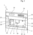
- Such a built-in device 1 has a designed as a trough-like depression storage area 15 which is bounded by a plurality of walls, of which in the FIG. 1 only the rear wall 16 and a side wall 17 can be seen.
- the lower part of the storage area 15 forms a storage area 18, on which a drinking vessel can be parked, which is filled with an infusion beverage produced in the built-in device 1.
- the storage area 18 also has a plurality of drainage openings 19, via which spilled or overflowed liquid residues can be discharged into a drip tray 25 arranged below the storage area 18.
- a milk container 20 integrated, which is detachably mounted here in a receptacle and thus recorded without contact with the storage area 18 in the storage area 15.
- the milk container 20 is placed on the shelf 18.
- an output device 3, on the underside of several beverage outlets 4 are present, which serve the delivery of the produced infusion drinks or beverage additions, such as milk or mixed drinks.
- Such a built-in device 1 has several, designed as panels 22 panel parts, which correspond mainly to aesthetic aspects.
- the entire front side is designed as a door 5, which can be opened and closed.
- the upper end of this door 5 forms an input and output area, which in the in FIG. 1 illustrated example, a display 23 in the form of a display and a keyboard 24 for programming or input of data.
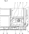
- FIG. 2 allows a partial view of the receiving space 6 of the built-in device 1, which is shown in the present example without the built-in device 1 closing door 5.
- the view into the receiving space 6 is possible in this form only if previously the water tank was removed from the receiving space 6. Only in this case, the brew unit 2 can be removed or used.
- a guide track 7, 8 rises up on both sides and in a ramp-like manner up to a height level that corresponds to the installation position of the brewing unit 2.
- the insertion direction opposite flanks of the guideways 7, 8 are circular arc in this example and include centrally a recess 13 in which a water tank valve 14 is located, via which the connection of the water tank, not shown, to the flow line system of the built-in appliance 1 for producing an infusion beverage he follows.
- the guideways 7, 8 extend to the rear wall 9 of the receiving space 6, where in addition a stop 10 is present, which forms a noticeable, so gemil perceptible stop when inserting the brewing unit 2 in the receiving space 6, which now shows the user a reversal is required, so that the brewing unit 2 then has to be pivoted behind the dispenser 3, where it reaches its end position, which is also perceived by an end stop gemilable.
- the drip tray 25 can be seen in a sectional view, which is located below the shelf 18 also shown in a sectional view.
- FIG. 3 shows in FIG. 3 a view into the receiving space 6 from a different perspective, more precisely in a viewing direction obliquely from below the built-in device 1.
- the receiving space 6 in the present example, two lights 11 and 12 in the form of LED lamps, the Illumination of the receiving space 6 serve.
- the left side of the receiving space 6 also arranged in its final position behind the dispenser 3 brewing unit 2 can be seen.
Landscapes
- Engineering & Computer Science (AREA)
- Food Science & Technology (AREA)
- Apparatus For Making Beverages (AREA)
- Devices For Dispensing Beverages (AREA)
Abstract
Description
- Die Erfindung betrifft ein Einbaugerät zur Herstellung von Aufgussgetränken nach dem Oberbegriff des Patentanspruches 1.
- Ein derartiges Einbaugerät umfasst neben zahlreichen Bauelementen insbesondere auch eine Heizeinrichtung zur Erhitzung von Wasser und/oder zur Herstellung von Wasserdampf, sodass das erhitzte Wasser zum Beispiel in einer ebenfalls vorhandenen Brüheinheit zur Aufbereitung des Aufgussgetränkes genutzt werden kann. Der gleichermaßen mit der Heizeinrichtung herstellbare Wasserdampf kommt in der Regel zum Einsatz, um Getränke oder Milch aufzuschäumen. Ein derartiges Einbaugerät weist einen zumeist als muldenartige Vertiefung ausgeführten Abstellbereich als Bestandteil einer den Innenraum des Einbaugerätes verschließenden Tür auf. Den unteren Teil des Abstellbereiches bildet dabei eine Abstellfläche, auf der ein Trinkgefäß abgestellt werden kann, das mit einem in dem Einbaugerät hergestellten Aufgussgetränk befüllt wird. Die Abstellfläche verfügt darüber hinaus über mehrere Ablauföffnungen, durch die verspritzte oder übergelaufene Flüssigkeitsreste in eine unterhalb der Abstellfläche angeordnete Abtropfschale abgeführt werden. Darüber hinaus ist in dem Abstellbereich eine Ausgabevorrichtung angeordnet, an deren Unterseite ein Getränkeauslass vorhanden ist. Es können natürlich auch mehrere Getränkeauslässe zur Abgabe der hergestellten Aufgussgetränke oder von Getränkezugaben, wie Milch, oder von Mischgetränken in das bereits erwähnte Trinkgefäß vorhanden sein. Ferner kann eine Dampfdüse dazu genutzt werden, Milchschaum zu erzeugen oder heißen Wasserdampf abzugeben.
Einbaugeräte der hier betroffenen Art weisen zudem die Besonderheit auf, dass sie in einen Küchenschrank oder in ein vergleichbares Möbelstück integriert sind und folglich nur ihre Frontseite sichtbar ist. Diese Frontseite wird als die eingangs bereits erwähnte und den Innenraum des Einbaugerätes verschließende Tür ausgeführt, die damit die Möglichkeit schafft, beispielsweise Reinigungs-, Reparatur- oder Wartungsarbeiten durchführen zu können beziehungsweise für den Betrieb des Einbaugerätes erforderliche Mittel, wie Kaffee, Tee oder Reinigungsmittel aufzufüllen. Insbesondere zu Reinigungszwecken ist es häufig erforderlich, einzelne Elemente aus dem Innenraum entnehmen zu können. Dies trifft beispielsweise auch auf die Brüheinheit zu. Aus dem genannten Grund ist die Brüheinheit bisher unmittelbar zugänglich, wenn die Tür des Einbaugerätes geöffnet ist. - Der Bezug des für die Herstellung von Aufgussgetränken erforderlichen Wassers kann aus einem Wassertank erfolgen, der ebenfalls hinter der verschließbaren Tür angeordnet ist. Es sind jedoch auch Ausführungen bekannt, die unmittelbar mit einem Wasseranschluss gekoppelt sind, sodass hierüber das benötigte Trinkwasser zur Verfügung gestellt wird oder der Wassertank automatisch befüllt wird, wenn er einen definierten Füllstand unterschritten hat. Ein häufig anzutreffendes Problem derartiger Einbaugeräte besteht darin, dass die Tür ein erhebliches Eigengewicht aufweist und daher sehr stabile Scharniere erfordert. Dies rührt daher, dass beispielsweise die Ausgabevorrichtung bislang in die Tür integriert ist, was darüber hinaus lösbare und miteinander koppelbare Anschlussleitungen erfordert, die naturgemäß im Laufe der Zeit zunehmend Probleme hinsichtlich der Abdichtung mit sich bringen. Der hierfür erforderliche konstruktive Aufwand ist erheblich und führt damit zu einem erhöhten Herstellungs- und Montageaufwand, sodass ein derartiges Einbaugerät insgesamt eine kostenintensive Fertigung erfordert.
- Der Erfindung stellt sich somit das Problem, ein Einbaugerät zur Herstellung von Aufgussgetränken bereitzustellen, dessen Aufbau insgesamt vereinfacht und kompakt ausgeführt ist und bei dem die im Innenraum angeordneten Bestandteile mit möglichst geringem Aufwand entfernt und anschließend wieder eingesetzt werden können.
- Erfindungsgemäß wird dieses unter anderem dieses Problem durch ein Einbaugerät zur Herstellung eines Aufgussgetränkes mit den Merkmalen des Patentanspruchs 1 gelöst. Vorteilhafte Ausgestaltungen und Weiterbildungen der Erfindung ergeben sich aus den nachfolgenden Unteransprüchen.
- Ein Einbaugerät zur Herstellung von Aufgussgetränken, das eine Heizeinrichtung zur Erhitzung von Wasser und/oder zur Herstellung von Wasserdampf, eine Brüheinheit zur Aufbereitung des Aufgussgetränkes mittels des erhitzten Wassers, eine Ausgabevorrichtung mit mindestens einem Getränkeauslass zur Abgabe des in dem Einbaugerät mittels der Brüheinheit hergestellten Aufgussgetränkes und eine das Einbaugerät verschließende Tür umfasst, wurde erfindungsgemäß dahingehend weitergebildet, dass hinter der geöffneten Tür des Einbaugerätes, ein Aufnahmeraum mit mindestens einer zum Einsetzen und zur Entnahme der Brüheinheit ausgeführten Führungsbahn vorhanden ist.
- Mit der Erfindung gelingt es erstmals, das Einbaugerät insgesamt wesentlich einfacher und im Aufbau kompakter zu gestalten, indem in der Tür keine Ausgabevorrichtung mehr vorhanden ist. Die Ausgabevorrichtung wird nunmehr in den Innenraum des Einbaugerätes integriert, was dazu führt, dass die Tür ein geringeres Gewicht aufweist. Die zum Öffnen und Schließen der Tür erforderlichen Scharniere können damit ebenfalls weniger kompakt ausgeführt sein. Aus diesem, im Vergleich zu bekannten Lösungen vollständig geänderten Konzept ergibt sich allerdings, dass die Brüheinheit nunmehr in einem Bereich hinter der Ausgabevorrichtung angeordnet werden muss, da seitlich neben der Ausgabevorrichtung ein Wassertank vorhanden ist. Aus dem genannten Grund geht die Erfindung dahin, den Aufnahmeraum zum Einsetzen des Wassertanks mit einer Doppelfunktion auszustatten. Einerseits weist er die ihm bisher zugewiesene Funktion der Aufnahme des Wassertanks auf und andererseits dient er dazu, die Brüheinheit über eine Führungsbahn geführt in ihrer Endposition zu verbringen. Hierfür wird bevorzugt, jedoch nicht zwingend, bodenseitig des Aufnahmeraumes eine Führungsbahn angeordnet, die die Brüheinheit zunächst in Richtung der Rückwand des Aufnahmeraumes führt, um sie anschließend umzulenken und seitlich in ihre Endlage zu verbringen. Dabei ist die Führungsbahn im Sinne einer Zwangsführung zu verstehen, was bedeutet, dass durch die Führung der Brüheinheit entlang der Führungsbahn eine fehlerhafte Montage der Brüheinheit zuverlässig ausgeschlossen werden kann.
- Dabei entspricht es einer ersten Ausgestaltung der Erfindung, dass die Führungsbahn als von der Tür in den Aufnahmeraum hinein ansteigende Rampe ausgeführt ist. Da der Aufnahmeraum gleichzeitig dem Einsetzen des Wassertanks dient, ist es nachvollziehbar, dass der Wassertank an seiner bodenseitigen Unterseite korrespondierend zu der Rampe Ausnehmungen aufweist. Die Montagereihenfolge ist dabei derart vorgesehen, dass bei entnommenem Wassertank zunächst die Brüheinheit in den Aufnahmeraum eingeführt und anschließend der Wassertank in den Aufnahmeraum eingesetzt wird. Bevorzugt werden Sensoren verwendet, die ein geeignetes Signal erzeugen, wenn versehentlich der Wassertank ohne die zuvor eingesetzte Brüheinheit in den Aufnahmeraum eingebracht wird.
- Wie zuvor bereits ausgeführt wurde, wird die Brüheinheit zunächst entlang der Führung in den Aufnahmeraum eingeführt und anschließend seitlich bewegt und hinter der Ausgabevorrichtung in ihrer Endlage positioniert. Dies hat zur Folge, dass der Aufnahmeraum eine C- oder L-Form aufweist. Die Führungsbahn wird erfindungsgemäß derart ausgeführt, dass die Brüheinheit nicht fehlerhaft montiert werden kann. Setzt der Anwender die Brüheinheit beispielsweise fehlerhaft also in einer falschen Einbaulage in den Aufnahmeraum ein, so lässt sich diese nicht entlang der Führungsbahn bewegen, was zur Folge hat, dass die Brüheinheit zunächst in ihre korrekte Position verbracht werden muss. Damit vermittelt die Führungsbahn dem Nutzer des Einbaugerätes eine spürbare, also haptisch wahrnehmbare Montagehilfe. Eine derartige Ausführung eines Einbaugerätes ist damit sogar für sehbehinderte Personen problemlos nutzbar.
- Eine sehr vorteilhafte, weiterbildende Maßnahme für die Erleichterung des Einsetzens der Brüheinheit in den Aufnahmeraum besteht ferner darin, dass die Führungsbahn an der Rückwand des Aufnahmeraumes einen haptisch wahrnehmbaren Anschlag zur Markierung eines Richtungswechsels aufweist. Auch diese Lösung trägt dazu bei, die Montage insgesamt wesentlich zu vereinfachen und dem Anwender eine Hilfestellung zu geben, wie die Brüheinheit korrekt montiert werden muss.
- Nachdem der erste, haptisch wahrnehmbare Anschlag im Bereich der Rückwand des Aufnahmeraumes erreicht wurde, wird die Brüheinheit über einen Richtungswechsel seitlich weitergeführt und dadurch hinter die Ausgabevorrichtung verbracht, wo sie ihre Endposition erreicht. Hierfür weist die Führungsbahn gemäß einer speziellen Ausgestaltung der Erfindung einen ebenfalls haptisch wahrnehmbaren Endanschlag als Markierung der erreichten Endlage der Einbauposition der Brüheinheit auf.
- Es ist vorstellbar, dass der Aufnahmeraum innerhalb des Einbaugerätes durch seine verwinkelte Gestalt Bereiche aufweist, die relativ schwer einsehbar sind. Grundsätzlich stellt dies kein Problem dar, da während des Einsetzens der Brüheinheit ein Anschlag beziehungsweise ein Endanschlag die korrekte Montage anzeigen. Dennoch ist es beispielsweise für Reinigungszwecke von Vorteil, wenn eine optimale Sicht innerhalb des Aufnahmeraumes möglich ist. Hierfür wird vorgeschlagen, dass der Aufnahmeraum eine Beleuchtung aufweist.
- Im Zuge von Energiesparmaßnahmen ist es dabei vorteilhaft, wenn die Beleuchtung aus mindestens einer LED-Lampe besteht. Zudem bringen derartige Beleuchtungen ein sehr helles Licht mit sich, sodass mit geringem Aufwand eine optimale Ausleuchtung des Aufnahmeraumes erreicht werden kann.
- Wie eingangs bereits ausgeführt wurde, weist der Aufnahmeraum eine Doppelfunktion auf, indem er die Brüheinheit und zusätzlich den für die Zubereitung von Aufgussgetränken mit Wasser befüllten Wassertank aufnimmt. Beide Elemente sind lösbar in den Aufnahmeraum eingesetzt und können folglich entnommen werden, wenn dies erforderlich ist.
- Die Führungsbahn wird bevorzugt rampenartig ausgeführt, sodass sie eine ansteigende Kontur aufweist. Diese Geometrie wird beim Wassertank als komplementäre Ausnehmung gestaltet, um den Wassertank bis an die Rückwand des Aufnahmeraumes in den Aufnahmeraum einsetzen und damit den vorhandenen Platz optimal ausnutzen zu können, was sich letztlich auch positiv auf das zur Verfügung stehende Wasservolumen auswirkt. Mittig weist die Führungsbahn zudem eine Ausnehmung auf, in die der Wassertank passgenau eingreift. In diesem Bereich befindet sich ein bei eingesetztem Wassertank mit diesem gekoppeltes Wassertankventil. Diese spezielle Art der Anordnung führt dazu, dass der Wassertank in den Aufnahmeraum eingesetzt wird und keine zusätzlichen Montagearbeiten erforderlich werden, um ihn mit dem Strömungsleitungssystem des Einbaugerätes zu koppeln. Nach dem Einsetzen des Wassertanks in den Aufnahmeraum kann folglich unmittelbar Wasser aus dem Wassertank entnommen werden, um damit ein Aufgussgetränk zuzubereiten.
- Die Erfindung wird nachfolgend anhand der beigefügten Zeichnungen näher erläutert. Das gezeigte Ausführungsbeispiel stellt dabei keine Einschränkung auf die dargestellte Variante dar, sondern dient lediglich der Erläuterung eines Prinzips der Erfindung.
Gleiche oder gleichartige Bauteile werden stets mit denselben Bezugsziffern bezeichnet. Um die erfindungsgemäße Funktionsweise veranschaulichen zu können, sind in den Figuren nur stark vereinfachte Prinzipdarstellungen gezeigt, bei denen auf die für die Erfindung nicht wesentlichen Bauteile verzichtet wurde. Dies bedeutet jedoch nicht, dass derartige Bauteile bei einer erfindungsgemäßen Lösung nicht vorhanden sind.
Es zeigt: - Figur 1:
- ausschnittsweise eine Frontansicht eines Einbaugerätes zur Herstellung eines Aufgussgetränkes
- Figur 2:
- ausschnittsweise einen Blick in den Aufnahmeraum eines Einbaugerätes in einer ersten Perspektive
- Figur 3:
- ausschnittsweise einen Blick in den Aufnahmeraum eines Einbaugerätes in einer zur
Figur 2 abweichenden Perspektive. - Bei dem in
Figur 1 gezeigten Einbaugerät 1 handelt es sich um einen Getränkebereiter zur Herstellung von Aufgussgetränken, also beispielsweise zur Zubereitung von Tee oder Kaffee. Die Besonderheit derartiger Einbaugeräte besteht darin, dass sie in einen Küchenschrank integriert werden und somit platzsparend untergebracht sind. Ein derartiges Einbaugerät 1 weist einen als muldenartige Vertiefung ausgeführten Abstellbereich 15 auf, der von mehreren Wänden begrenzt ist, von denen in derFigur 1 lediglich die Rückwand 16 und eine Seitenwand 17 erkennbar sind. Den unteren Teil des Abstellbereiches 15 bildet eine Abstellfläche 18, auf der ein Trinkgefäß abgestellt werden kann, das mit einem in dem Einbaugerät 1 hergestellten Aufgussgetränk befüllt wird. Die Abstellfläche 18 weist darüber hinaus mehrere Ablauföffnungen 19 auf, über die verspritzte oder übergelaufene Flüssigkeitsreste in eine unterhalb der Abstellfläche 18 angeordnete Abtropfschale 25 abgeführt werden können. In den Abstellbereich 15 ist bei dem Beispiel inFigur 1 darüber hinaus ein Milchgefäß 20 integriert, welches hier in eine Aufnahme lösbar eingehängt und somit ohne Berührungskontakt zu der Abstellfläche 18 in dem Abstellbereich 15 aufgenommen ist. Es sind jedoch auch Varianten möglich, bei denen das Milchgefäß 20 auf der Abstellfläche 18 abgestellt wird. Darüber hinaus mündet in den Abstellbereich 15 eine Ausgabevorrichtung 3, an deren Unterseite mehrere Getränkeauslässe 4 vorhanden sind, die der Abgabe der hergestellten Aufgussgetränke oder von Getränkezugaben, wie Milch oder von Mischgetränken dienen. Seitlich neben der Ausgabevorrichtung 3 ist ferner eine Dampfdüse 21 vorhanden, die zur Erzeugung von Milchschaum nutzbar ist oder der Abgabe von heißen Wasserdampf dient.
Ein derartiges Einbaugerät 1 weist mehrere, als Blenden 22 ausgeführte Verkleidungsteile auf, die hauptsächlich ästhetischen Gesichtspunkten entsprechen. Um den Innenraum eines derartigen Einbaugerätes 1 zugänglich zu machen, ist die gesamte Frontseite als eine Tür 5 ausgeführt, die geöffnet und verschlossen werden kann. Den oberen Abschluss dieser Tür 5 bildet ein Ein- und Ausgabebereich, der bei dem inFigur 1 dargestellten Beispiel eine Anzeige 23 in Form eines Displays und eine Tastatur 24 zur Programmierung beziehungsweise Eingabe von Daten aufweist. - Die
Figur 2 erlaubt ausschnittsweise einen Blick in den Aufnahmeraum 6 des Einbaugerätes 1, das im vorliegenden Beispiel ohne eine das Einbaugerät 1 verschließende Tür 5 dargestellt ist. Der Blick in den Aufnahmeraum 6 ist in dieser Form nur möglich, wenn zuvor der Wassertank aus dem Aufnahmeraum 6 entnommen wurde. Nur in diesem Fall kann die Brüheinheit 2 entnommen oder eingesetzt werden. Vom Boden 26 des Aufnahmeraumes 6 ausgehend erhebt sich beidseitig und rampenartig ansteigend je eine Führungsbahn 7, 8 bis in ein Höhenniveau, dass der Einbauposition der Brüheinheit 2 entspricht. Die der Einschubrichtung entgegengesetzten Flanken der Führungsbahnen 7, 8 sind bei diesem Beispiel kreisbogenförmig ausgeführt und schließen mittig eine Ausnehmung 13 ein, in der sich ein Wassertankventil 14 befindet, über das der Anschluss des nicht gezeigten Wassertanks an das Strömungsleitungssystem des Einbaugerätes 1 zur Herstellung eines Aufgussgetränkes erfolgt. Die Führungsbahnen 7, 8 verlaufen bis zur Rückwand 9 des Aufnahmeraumes 6, wo darüber hinaus ein Anschlag 10 vorhanden ist, der beim Einsetzen der Brüheinheit 2 in den Aufnahmeraum 6 einen spürbaren, also habtil wahrnehmbaren Anschlag bildet, der dem Anwender zeigt das nunmehr eine Richtungsumkehr erforderlich ist, sodass die Brüheinheit 2 anschließend hinter die Ausgabevorrichtung 3 geschwenkt werden muss, wo sie ihre Endposition erreicht, die ebenfalls durch einen Endanschlag habtil wahrnehmbar ausgeführt ist. In derFigur 2 ist zudem die Abtropfschale 25 in geschnittener Darstellung erkennbar, die sich unterhalb der ebenfalls in geschnittener Darstellung gezeigten Abstellfläche 18 befindet. - Schließlich zeigt die Darstellung in
Figur 3 einen Blick in den Aufnahmeraum 6 aus einer anderen Perspektive, genauer gesagt in einer Blickrichtung von schräg unten auf das Einbaugerät 1. Daraus wird ersichtlich, dass der Aufnahmeraum 6 im vorliegenden Beispiel zwei Beleuchtungen 11 und 12 in Form von LED-Lampen aufweist, die der Beleuchtung des Aufnahmeraumes 6 dienen. Auf der linken Seite des Aufnahmeraumes 6 ist zudem die in ihrer Endposition hinter der Ausgabevorrichtung 3 angeordnete Brüheinheit 2 erkennbar. -
- 1
- Einbaugerät
- 2
- Brüheinheit
- 3
- Ausgabevorrichtung
- 4
- Getränkeauslass
- 5
- Tür
- 6
- Aufnahmeraum
- 7
- Führungsbahn
- 8
- Führungsbahn
- 9
- Rückwand (Aufnahmeraum)
- 10
- Anschlag
- 11
- Beleuchtung (LED)
- 12
- Beleuchtung (LED)
- 13
- Ausnehmung
- 14
- Wassertankventil
- 15
- Abstellbereich
- 16
- Rückwand (Abstellbereich)
- 17
- Seitenwand
- 18
- Abstellfläche
- 19
- Ablauföffnungen
- 20
- Milchgefäß
- 21
- Dampfdüse
- 22
- Blende
- 23
- Display
- 24
- Tastatur
- 25
- Abtropfschale
- 26
- Boden (Aufnahmeraum)
Claims (10)
- Einbaugerät (1) zur Herstellung von Aufgussgetränken, umfassend:- eine Heizeinrichtung zur Erhitzung von Wasser und/oder zur Herstellung von Wasserdampf,- eine Brüheinheit (2) zur Aufbereitung des Aufgussgetränkes mittels des erhitzten Wassers,- eine Ausgabevorrichtung (3) mit mindestens einem Getränkeauslass (4) zur Abgabe des in dem Einbaugerät (1) mittels der Brüheinheit (2) hergestellten Aufgussgetränkes,- eine das Einbaugerät (1) verschließende Tür (5),dadurch gekennzeichnet, dass
hinter der geöffneten Tür (5) des Einbaugerätes (1), ein Aufnahmeraum (6) mit mindestens einer zum Einsetzen und zur Entnahme der Brüheinheit (2) ausgeführten Führungsbahn (7, 8) vorhanden ist. - Einbaugerät nach Anspruch 1,
dadurch gekennzeichnet, dass
die Führungsbahn (7, 8) als von der Tür (5) in den Aufnahmeraum (6) hinein ansteigende Rampe ausgeführt ist. - Einbaugerät nach einem der vorstehend ausgeführten Ansprüche,
dadurch gekennzeichnet, dass
der Aufnahmeraum (6) eine C- oder L-Form aufweist, sodass die Brüheinheit sich in ihrer Endposition hinter der Ausgabevorrichtung (3) befindet. - Einbaugerät nach einem der vorstehend ausgeführten Ansprüche,
dadurch gekennzeichnet, dass
die Führungsbahn (7, 8) an der Rückwand (9) des Aufnahmeraumes (6) einen haptisch wahrnehmbaren Anschlag (10) zur Markierung eines Richtungswechsels aufweist. - Einbaugerät nach Anspruch 4,
dadurch gekennzeichnet, dass
die Führungsbahn (7, 8) einen haptisch wahrnehmbaren Endanschlag als Markierung der erreichten Einbauposition der Brüheinheit (2) aufweist. - Einbaugerät nach einem der vorstehend ausgeführten Ansprüche,
dadurch gekennzeichnet, dass
der Aufnahmeraum (6) eine Beleuchtung (11,12) aufweist. - Einbaugerät nach Anspruch 6,
dadurch gekennzeichnet, dass
die Beleuchtung (11, 12) aus mindestens einer LED -Lampe besteht. - Einbaugerät nach einem der vorstehend ausgeführten Ansprüche,
dadurch gekennzeichnet, dass
in den Aufnahmeraum (6) bei eingesetzter Brüheinheit (2) zusätzlich ein Wassertank einsetzbar ist. - Einbaugerät nach einem der vorstehend ausgeführten Ansprüche,
dadurch gekennzeichnet, dass
die Führungsbahn (7, 8) mittig eine Ausnehmung (13) aufweist, in die der Wassertank passgenau einsetzbar ist. - Einbaugerät nach Anspruch 9,
dadurch gekennzeichnet, dass
die Ausnehmung (13) ein bei eingesetztem Wassertank mit diesem gekuppeltes Wassertankventil (14) aufweist.
Applications Claiming Priority (1)
| Application Number | Priority Date | Filing Date | Title |
|---|---|---|---|
| DE102018104272.8A DE102018104272A1 (de) | 2018-02-26 | 2018-02-26 | Einbaugerät zur Herstellung von Aufgussgetränken |
Publications (2)
| Publication Number | Publication Date |
|---|---|
| EP3530154A1 true EP3530154A1 (de) | 2019-08-28 |
| EP3530154B1 EP3530154B1 (de) | 2020-11-11 |
Family
ID=65138846
Family Applications (1)
| Application Number | Title | Priority Date | Filing Date |
|---|---|---|---|
| EP19152701.9A Active EP3530154B1 (de) | 2018-02-26 | 2019-01-21 | Einbaugerät zur herstellung von aufgussgetränken |
Country Status (2)
| Country | Link |
|---|---|
| EP (1) | EP3530154B1 (de) |
| DE (1) | DE102018104272A1 (de) |
Citations (2)
| Publication number | Priority date | Publication date | Assignee | Title |
|---|---|---|---|---|
| DE102005048164A1 (de) * | 2005-09-12 | 2007-03-15 | Miele & Cie. Kg | Getränkebereiter, insbesondere Kaffeeautomat |
| EP2677906A1 (de) * | 2011-02-25 | 2014-01-01 | Koninklijke Philips N.V. | Brauanordnung und getränkeproduktionsmaschine mit dieser anordnung |
Family Cites Families (1)
| Publication number | Priority date | Publication date | Assignee | Title |
|---|---|---|---|---|
| DE102016119020A1 (de) * | 2016-10-07 | 2018-04-12 | Eugster/Frismag Ag | Kaffeevollautomat |
-
2018
- 2018-02-26 DE DE102018104272.8A patent/DE102018104272A1/de not_active Withdrawn
-
2019
- 2019-01-21 EP EP19152701.9A patent/EP3530154B1/de active Active
Patent Citations (2)
| Publication number | Priority date | Publication date | Assignee | Title |
|---|---|---|---|---|
| DE102005048164A1 (de) * | 2005-09-12 | 2007-03-15 | Miele & Cie. Kg | Getränkebereiter, insbesondere Kaffeeautomat |
| EP2677906A1 (de) * | 2011-02-25 | 2014-01-01 | Koninklijke Philips N.V. | Brauanordnung und getränkeproduktionsmaschine mit dieser anordnung |
Non-Patent Citations (2)
| Title |
|---|
| MANIEK GISZ: "Siemens CT 636 les1", 16 April 2016 (2016-04-16), pages 1 - 2, XP054979307, Retrieved from the Internet <URL:https://www.youtube.com/watch?v=rZCkxXYJ5tg> [retrieved on 20160416] * |
| WEERT FRANZEN: "Neff Kaffeevollautomat c77v60 / Reinigung", YOUTUBE, 21 December 2014 (2014-12-21), XP054979302, Retrieved from the Internet <URL:https://www.youtube.com/watch?v=8SeEoGRLzkA> [retrieved on 20190412] * |
Also Published As
| Publication number | Publication date |
|---|---|
| EP3530154B1 (de) | 2020-11-11 |
| DE102018104272A1 (de) | 2019-08-29 |
Similar Documents
| Publication | Publication Date | Title |
|---|---|---|
| EP0783859B1 (de) | Getränkebereiter | |
| EP3364829B1 (de) | Getränkezubereitungsmaschine | |
| EP1051941B1 (de) | Kaffeemaschinenanordnung | |
| EP2628420B1 (de) | Heißgetränkezubereitungsvorrichtung | |
| DE102014100732B4 (de) | Heißgetränkeautomat mit einer Füllstandsanzeige | |
| EP2323523A2 (de) | Halteeinrichtung | |
| EP2190329B1 (de) | Getränkebereiter | |
| EP3099208A1 (de) | Aromamodul sowie verfahren zum betrieb eines solchen aromamoduls | |
| EP2721975B1 (de) | Getränkebereiter | |
| EP3291716B1 (de) | Getränkezubereitungsmaschine | |
| DE102008042177A1 (de) | Getränkeautomat | |
| EP3270750B1 (de) | Getränkebereiter, insbesondere kaffeemaschine, für festwasseranschluss sowie festwasserkit | |
| EP2548481B1 (de) | Getränkeautomat mit einem Getränkeauslauf | |
| EP3061370A1 (de) | Getränkezubereitungsmaschine | |
| EP3530154B1 (de) | Einbaugerät zur herstellung von aufgussgetränken | |
| WO2016008676A1 (de) | Haushaltskältegerät mit einer wasserspendereinheit die eine aufnahmeeinheit zum einsetzen eines geschmacksmittel-behälters aufweist | |
| DE102013109541B4 (de) | Anordnung mit einer Verstellvorrichtung und einem Heißgetränkeautomaten | |
| EP2732741B1 (de) | Getränkebereiter mit einem Zentralauslauf | |
| EP3530155B1 (de) | Einbaugerät zur herstellung von aufgussgetränken | |
| DE102018104276A1 (de) | Einbaugerät zur Herstellung von Aufgussgetränken | |
| DE1133586B (de) | Selbstverkaeufer zum Vertrieb von aus Wasser und Zutaten herzustellenden Getraenken | |
| WO2022033887A1 (de) | Getränkeausgabemaschine | |
| DE7122740U (de) | Getraenkezapfgeraet | |
| DE202004003754U1 (de) | Getränkespender | |
| DE1429805A1 (de) | Kaffeemaschine |
Legal Events
| Date | Code | Title | Description |
|---|---|---|---|
| PUAI | Public reference made under article 153(3) epc to a published international application that has entered the european phase |
Free format text: ORIGINAL CODE: 0009012 |
|
| STAA | Information on the status of an ep patent application or granted ep patent |
Free format text: STATUS: THE APPLICATION HAS BEEN PUBLISHED |
|
| AK | Designated contracting states |
Kind code of ref document: A1 Designated state(s): AL AT BE BG CH CY CZ DE DK EE ES FI FR GB GR HR HU IE IS IT LI LT LU LV MC MK MT NL NO PL PT RO RS SE SI SK SM TR |
|
| AX | Request for extension of the european patent |
Extension state: BA ME |
|
| STAA | Information on the status of an ep patent application or granted ep patent |
Free format text: STATUS: REQUEST FOR EXAMINATION WAS MADE |
|
| 17P | Request for examination filed |
Effective date: 20200228 |
|
| RBV | Designated contracting states (corrected) |
Designated state(s): AL AT BE BG CH CY CZ DE DK EE ES FI FR GB GR HR HU IE IS IT LI LT LU LV MC MK MT NL NO PL PT RO RS SE SI SK SM TR |
|
| GRAP | Despatch of communication of intention to grant a patent |
Free format text: ORIGINAL CODE: EPIDOSNIGR1 |
|
| STAA | Information on the status of an ep patent application or granted ep patent |
Free format text: STATUS: GRANT OF PATENT IS INTENDED |
|
| INTG | Intention to grant announced |
Effective date: 20200715 |
|
| GRAS | Grant fee paid |
Free format text: ORIGINAL CODE: EPIDOSNIGR3 |
|
| GRAA | (expected) grant |
Free format text: ORIGINAL CODE: 0009210 |
|
| STAA | Information on the status of an ep patent application or granted ep patent |
Free format text: STATUS: THE PATENT HAS BEEN GRANTED |
|
| AK | Designated contracting states |
Kind code of ref document: B1 Designated state(s): AL AT BE BG CH CY CZ DE DK EE ES FI FR GB GR HR HU IE IS IT LI LT LU LV MC MK MT NL NO PL PT RO RS SE SI SK SM TR |
|
| REG | Reference to a national code |
Ref country code: GB Ref legal event code: FG4D Free format text: NOT ENGLISH |
|
| REG | Reference to a national code |
Ref country code: CH Ref legal event code: NV Representative=s name: COSMOVICI INTELLECTUAL PROPERTY SARL, CH Ref country code: CH Ref legal event code: EP |
|
| REG | Reference to a national code |
Ref country code: AT Ref legal event code: REF Ref document number: 1332641 Country of ref document: AT Kind code of ref document: T Effective date: 20201115 |
|
| REG | Reference to a national code |
Ref country code: DE Ref legal event code: R096 Ref document number: 502019000377 Country of ref document: DE |
|
| REG | Reference to a national code |
Ref country code: NL Ref legal event code: FP Ref country code: IE Ref legal event code: FG4D Free format text: LANGUAGE OF EP DOCUMENT: GERMAN |
|
| PG25 | Lapsed in a contracting state [announced via postgrant information from national office to epo] |
Ref country code: GR Free format text: LAPSE BECAUSE OF FAILURE TO SUBMIT A TRANSLATION OF THE DESCRIPTION OR TO PAY THE FEE WITHIN THE PRESCRIBED TIME-LIMIT Effective date: 20210212 Ref country code: NO Free format text: LAPSE BECAUSE OF FAILURE TO SUBMIT A TRANSLATION OF THE DESCRIPTION OR TO PAY THE FEE WITHIN THE PRESCRIBED TIME-LIMIT Effective date: 20210211 Ref country code: FI Free format text: LAPSE BECAUSE OF FAILURE TO SUBMIT A TRANSLATION OF THE DESCRIPTION OR TO PAY THE FEE WITHIN THE PRESCRIBED TIME-LIMIT Effective date: 20201111 Ref country code: RS Free format text: LAPSE BECAUSE OF FAILURE TO SUBMIT A TRANSLATION OF THE DESCRIPTION OR TO PAY THE FEE WITHIN THE PRESCRIBED TIME-LIMIT Effective date: 20201111 Ref country code: PT Free format text: LAPSE BECAUSE OF FAILURE TO SUBMIT A TRANSLATION OF THE DESCRIPTION OR TO PAY THE FEE WITHIN THE PRESCRIBED TIME-LIMIT Effective date: 20210311 |
|
| PG25 | Lapsed in a contracting state [announced via postgrant information from national office to epo] |
Ref country code: SE Free format text: LAPSE BECAUSE OF FAILURE TO SUBMIT A TRANSLATION OF THE DESCRIPTION OR TO PAY THE FEE WITHIN THE PRESCRIBED TIME-LIMIT Effective date: 20201111 Ref country code: BG Free format text: LAPSE BECAUSE OF FAILURE TO SUBMIT A TRANSLATION OF THE DESCRIPTION OR TO PAY THE FEE WITHIN THE PRESCRIBED TIME-LIMIT Effective date: 20210211 Ref country code: PL Free format text: LAPSE BECAUSE OF FAILURE TO SUBMIT A TRANSLATION OF THE DESCRIPTION OR TO PAY THE FEE WITHIN THE PRESCRIBED TIME-LIMIT Effective date: 20201111 Ref country code: LV Free format text: LAPSE BECAUSE OF FAILURE TO SUBMIT A TRANSLATION OF THE DESCRIPTION OR TO PAY THE FEE WITHIN THE PRESCRIBED TIME-LIMIT Effective date: 20201111 Ref country code: IS Free format text: LAPSE BECAUSE OF FAILURE TO SUBMIT A TRANSLATION OF THE DESCRIPTION OR TO PAY THE FEE WITHIN THE PRESCRIBED TIME-LIMIT Effective date: 20210311 |
|
| REG | Reference to a national code |
Ref country code: LT Ref legal event code: MG9D |
|
| PG25 | Lapsed in a contracting state [announced via postgrant information from national office to epo] |
Ref country code: HR Free format text: LAPSE BECAUSE OF FAILURE TO SUBMIT A TRANSLATION OF THE DESCRIPTION OR TO PAY THE FEE WITHIN THE PRESCRIBED TIME-LIMIT Effective date: 20201111 |
|
| PG25 | Lapsed in a contracting state [announced via postgrant information from national office to epo] |
Ref country code: RO Free format text: LAPSE BECAUSE OF FAILURE TO SUBMIT A TRANSLATION OF THE DESCRIPTION OR TO PAY THE FEE WITHIN THE PRESCRIBED TIME-LIMIT Effective date: 20201111 Ref country code: LT Free format text: LAPSE BECAUSE OF FAILURE TO SUBMIT A TRANSLATION OF THE DESCRIPTION OR TO PAY THE FEE WITHIN THE PRESCRIBED TIME-LIMIT Effective date: 20201111 Ref country code: CZ Free format text: LAPSE BECAUSE OF FAILURE TO SUBMIT A TRANSLATION OF THE DESCRIPTION OR TO PAY THE FEE WITHIN THE PRESCRIBED TIME-LIMIT Effective date: 20201111 Ref country code: EE Free format text: LAPSE BECAUSE OF FAILURE TO SUBMIT A TRANSLATION OF THE DESCRIPTION OR TO PAY THE FEE WITHIN THE PRESCRIBED TIME-LIMIT Effective date: 20201111 Ref country code: SK Free format text: LAPSE BECAUSE OF FAILURE TO SUBMIT A TRANSLATION OF THE DESCRIPTION OR TO PAY THE FEE WITHIN THE PRESCRIBED TIME-LIMIT Effective date: 20201111 Ref country code: SM Free format text: LAPSE BECAUSE OF FAILURE TO SUBMIT A TRANSLATION OF THE DESCRIPTION OR TO PAY THE FEE WITHIN THE PRESCRIBED TIME-LIMIT Effective date: 20201111 |
|
| REG | Reference to a national code |
Ref country code: DE Ref legal event code: R097 Ref document number: 502019000377 Country of ref document: DE |
|
| PG25 | Lapsed in a contracting state [announced via postgrant information from national office to epo] |
Ref country code: MC Free format text: LAPSE BECAUSE OF FAILURE TO SUBMIT A TRANSLATION OF THE DESCRIPTION OR TO PAY THE FEE WITHIN THE PRESCRIBED TIME-LIMIT Effective date: 20201111 Ref country code: DK Free format text: LAPSE BECAUSE OF FAILURE TO SUBMIT A TRANSLATION OF THE DESCRIPTION OR TO PAY THE FEE WITHIN THE PRESCRIBED TIME-LIMIT Effective date: 20201111 |
|
| PLBE | No opposition filed within time limit |
Free format text: ORIGINAL CODE: 0009261 |
|
| STAA | Information on the status of an ep patent application or granted ep patent |
Free format text: STATUS: NO OPPOSITION FILED WITHIN TIME LIMIT |
|
| PG25 | Lapsed in a contracting state [announced via postgrant information from national office to epo] |
Ref country code: LU Free format text: LAPSE BECAUSE OF NON-PAYMENT OF DUE FEES Effective date: 20210121 |
|
| 26N | No opposition filed |
Effective date: 20210812 |
|
| PG25 | Lapsed in a contracting state [announced via postgrant information from national office to epo] |
Ref country code: FR Free format text: LAPSE BECAUSE OF NON-PAYMENT OF DUE FEES Effective date: 20210131 Ref country code: IT Free format text: LAPSE BECAUSE OF FAILURE TO SUBMIT A TRANSLATION OF THE DESCRIPTION OR TO PAY THE FEE WITHIN THE PRESCRIBED TIME-LIMIT Effective date: 20201111 Ref country code: AL Free format text: LAPSE BECAUSE OF FAILURE TO SUBMIT A TRANSLATION OF THE DESCRIPTION OR TO PAY THE FEE WITHIN THE PRESCRIBED TIME-LIMIT Effective date: 20201111 |
|
| PG25 | Lapsed in a contracting state [announced via postgrant information from national office to epo] |
Ref country code: SI Free format text: LAPSE BECAUSE OF FAILURE TO SUBMIT A TRANSLATION OF THE DESCRIPTION OR TO PAY THE FEE WITHIN THE PRESCRIBED TIME-LIMIT Effective date: 20201111 |
|
| PG25 | Lapsed in a contracting state [announced via postgrant information from national office to epo] |
Ref country code: ES Free format text: LAPSE BECAUSE OF FAILURE TO SUBMIT A TRANSLATION OF THE DESCRIPTION OR TO PAY THE FEE WITHIN THE PRESCRIBED TIME-LIMIT Effective date: 20201111 Ref country code: IE Free format text: LAPSE BECAUSE OF NON-PAYMENT OF DUE FEES Effective date: 20210121 |
|
| PG25 | Lapsed in a contracting state [announced via postgrant information from national office to epo] |
Ref country code: IS Free format text: LAPSE BECAUSE OF FAILURE TO SUBMIT A TRANSLATION OF THE DESCRIPTION OR TO PAY THE FEE WITHIN THE PRESCRIBED TIME-LIMIT Effective date: 20210311 |
|
| PG25 | Lapsed in a contracting state [announced via postgrant information from national office to epo] |
Ref country code: CY Free format text: LAPSE BECAUSE OF FAILURE TO SUBMIT A TRANSLATION OF THE DESCRIPTION OR TO PAY THE FEE WITHIN THE PRESCRIBED TIME-LIMIT Effective date: 20201111 |
|
| P01 | Opt-out of the competence of the unified patent court (upc) registered |
Effective date: 20230526 |
|
| PG25 | Lapsed in a contracting state [announced via postgrant information from national office to epo] |
Ref country code: HU Free format text: LAPSE BECAUSE OF FAILURE TO SUBMIT A TRANSLATION OF THE DESCRIPTION OR TO PAY THE FEE WITHIN THE PRESCRIBED TIME-LIMIT; INVALID AB INITIO Effective date: 20190121 |
|
| PG25 | Lapsed in a contracting state [announced via postgrant information from national office to epo] |
Ref country code: MK Free format text: LAPSE BECAUSE OF FAILURE TO SUBMIT A TRANSLATION OF THE DESCRIPTION OR TO PAY THE FEE WITHIN THE PRESCRIBED TIME-LIMIT Effective date: 20201111 |
|
| PG25 | Lapsed in a contracting state [announced via postgrant information from national office to epo] |
Ref country code: TR Free format text: LAPSE BECAUSE OF FAILURE TO SUBMIT A TRANSLATION OF THE DESCRIPTION OR TO PAY THE FEE WITHIN THE PRESCRIBED TIME-LIMIT Effective date: 20201111 |
|
| PG25 | Lapsed in a contracting state [announced via postgrant information from national office to epo] |
Ref country code: MT Free format text: LAPSE BECAUSE OF FAILURE TO SUBMIT A TRANSLATION OF THE DESCRIPTION OR TO PAY THE FEE WITHIN THE PRESCRIBED TIME-LIMIT Effective date: 20201111 |
|
| REG | Reference to a national code |
Ref country code: AT Ref legal event code: MM01 Ref document number: 1332641 Country of ref document: AT Kind code of ref document: T Effective date: 20240121 |
|
| PG25 | Lapsed in a contracting state [announced via postgrant information from national office to epo] |
Ref country code: AT Free format text: LAPSE BECAUSE OF NON-PAYMENT OF DUE FEES Effective date: 20240121 |
|
| REG | Reference to a national code |
Ref country code: CH Ref legal event code: U11 Free format text: ST27 STATUS EVENT CODE: U-0-0-U10-U11 (AS PROVIDED BY THE NATIONAL OFFICE) Effective date: 20260201 |
|
| PGFP | Annual fee paid to national office [announced via postgrant information from national office to epo] |
Ref country code: NL Payment date: 20260122 Year of fee payment: 8 |
|
| PGFP | Annual fee paid to national office [announced via postgrant information from national office to epo] |
Ref country code: GB Payment date: 20260126 Year of fee payment: 8 |
|
| PGFP | Annual fee paid to national office [announced via postgrant information from national office to epo] |
Ref country code: DE Payment date: 20260131 Year of fee payment: 8 |
|
| PGFP | Annual fee paid to national office [announced via postgrant information from national office to epo] |
Ref country code: AT Payment date: 20260410 Year of fee payment: 5 |
|
| PGFP | Annual fee paid to national office [announced via postgrant information from national office to epo] |
Ref country code: BE Payment date: 20260123 Year of fee payment: 8 |
|
| PGFP | Annual fee paid to national office [announced via postgrant information from national office to epo] |
Ref country code: CH Payment date: 20260201 Year of fee payment: 8 |