EP3530104A1 - Diviseur de récolte actif pour tête de coupe - Google Patents
Diviseur de récolte actif pour tête de coupe Download PDFInfo
- Publication number
- EP3530104A1 EP3530104A1 EP19158171.9A EP19158171A EP3530104A1 EP 3530104 A1 EP3530104 A1 EP 3530104A1 EP 19158171 A EP19158171 A EP 19158171A EP 3530104 A1 EP3530104 A1 EP 3530104A1
- Authority
- EP
- European Patent Office
- Prior art keywords
- header
- crop
- crop divider
- divider
- frame
- Prior art date
- Legal status (The legal status is an assumption and is not a legal conclusion. Google has not performed a legal analysis and makes no representation as to the accuracy of the status listed.)
- Granted
Links
- 239000000463 material Substances 0.000 claims abstract description 44
- 238000000034 method Methods 0.000 claims description 4
- 238000003306 harvesting Methods 0.000 description 9
- 238000004140 cleaning Methods 0.000 description 4
- 239000010902 straw Substances 0.000 description 4
- 238000012545 processing Methods 0.000 description 3
- 230000008901 benefit Effects 0.000 description 2
- 239000012530 fluid Substances 0.000 description 2
- 230000006870 function Effects 0.000 description 2
- 238000012986 modification Methods 0.000 description 2
- 230000004048 modification Effects 0.000 description 2
- 230000003287 optical effect Effects 0.000 description 2
- 230000032258 transport Effects 0.000 description 2
- 238000011144 upstream manufacturing Methods 0.000 description 2
- 235000014698 Brassica juncea var multisecta Nutrition 0.000 description 1
- 235000006008 Brassica napus var napus Nutrition 0.000 description 1
- 240000000385 Brassica napus var. napus Species 0.000 description 1
- 235000006618 Brassica rapa subsp oleifera Nutrition 0.000 description 1
- 235000004977 Brassica sinapistrum Nutrition 0.000 description 1
- 235000010469 Glycine max Nutrition 0.000 description 1
- 244000068988 Glycine max Species 0.000 description 1
- 238000004891 communication Methods 0.000 description 1
- 238000013461 design Methods 0.000 description 1
- 238000011143 downstream manufacturing Methods 0.000 description 1
- 239000002184 metal Substances 0.000 description 1
- 238000003860 storage Methods 0.000 description 1
Images


Classifications
-
- A—HUMAN NECESSITIES
- A01—AGRICULTURE; FORESTRY; ANIMAL HUSBANDRY; HUNTING; TRAPPING; FISHING
- A01D—HARVESTING; MOWING
- A01D63/00—Outside dividers
- A01D63/02—Rotating dividers
-
- A—HUMAN NECESSITIES
- A01—AGRICULTURE; FORESTRY; ANIMAL HUSBANDRY; HUNTING; TRAPPING; FISHING
- A01D—HARVESTING; MOWING
- A01D57/00—Delivering mechanisms for harvesters or mowers
- A01D57/01—Devices for leading crops to the mowing apparatus
-
- A—HUMAN NECESSITIES
- A01—AGRICULTURE; FORESTRY; ANIMAL HUSBANDRY; HUNTING; TRAPPING; FISHING
- A01D—HARVESTING; MOWING
- A01D69/00—Driving mechanisms or parts thereof for harvesters or mowers
- A01D69/03—Driving mechanisms or parts thereof for harvesters or mowers fluid
Definitions
- the present invention pertains to headers for agricultural vehicles and, more specifically, to headers which include crop dividers.
- a combine An agricultural harvester known as a "combine” is historically termed such because it combines multiple harvesting functions with a single harvesting unit, such as picking, threshing, separating, and cleaning.
- a combine includes a header which removes the crop from a field, and a feeder housing which transports the crop matter into a threshing rotor.
- the threshing rotor rotates within a perforated housing, which may be in the form of adjustable concaves, and performs a threshing operation on the crop to remove the grain.
- the threshing rotor is provided with rasp bars that interact with the crop matter in order to further separate the grain from the crop matter, and to provide positive crop movement. Once the grain is threshed, the grain is cleaned using a cleaning system.
- the cleaning system includes a cleaning fan which blows air through oscillating sieves to discharge chaff and other debris toward the rear of the combine.
- Non-grain crop material, such as straw, from the threshing section proceeds through a straw chopper and out the rear of the combine. Clean grain is transported to a grain tank onboard the combine.
- a typical header generally includes a frame, a pair of end dividers at the lateral ends of the frame, a cutter to remove crop material from the field, and a conveyor to transport the cut crop material to the feeder housing for further downstream processing in the combine.
- These features of a typical header are generally specifically optimized to harvest a particular kind of crop material.
- the header may be in the form of a draper header which has a cutter bar, a draper belt, and a rotating reel with tines or the like in order to harvest a bushy or fluffy crop material, such as soy beans or canola.
- Crop dividers on a header can cause a decrease in yield because the crop dividers may ineffectively direct crop material into the header.
- some end dividers may push or lay crop material over as it divides a row of crop material, and thereby, on a subsequent pass it may be difficult to harvest the down crop material which the end dividers have pushed or laid over.
- the shape of some dividers may cause an operator to stop the harvesting process and physically remove the lodged crop material.
- Some headers may further include a down crop attachment located on one or more crop dividers in order to move bent, fallen, or lodged crop material from the front of the header towards the conveyor.
- a down crop attachment may include a rotating chain or belt located at the center of the crop divider. Incorporating a down crop attachment can decrease economic loss, since the bent, fallen, and/or lodged crop material would not otherwise be gathered into the header. Additionally, the down crop attachment will increase the harvesting efficiency as the operator does not need to stop the harvesting process to clean lodged crop material from the header as often. However, down crop attachments may be complex and cumbersome to maintain. Additionally, some down crop attachments can undesirably increase the overall weight of the header.
- a header that includes rotating end crop dividers and drive units for rotating the end crop dividers in order to separate and lift crop material into the header.
- an agricultural vehicle including a chassis and a header connected to the chassis.
- the header includes a frame and at least one crop divider rotatably connected to the frame at an axis of rotation.
- the at least one crop divider is configured for dividing and lifting a crop material.
- the header also includes at least one drive unit mounted to the frame and operably connected to the at least one crop divider such that as the header is moved in a forward direction the at least one drive unit rotates the at least one crop divider about the axis of rotation.
- a header for an agricultural vehicle including a frame and at least one crop divider rotatably connected to the frame at an axis of rotation.
- the at least one crop divider is configured for dividing and lifting a crop material.
- the header also includes at least one drive unit mounted to the frame and operably connected to the at least one crop divider such that as the header is moved in a forward direction the at least one drive unit rotates the at least one crop divider about the axis of rotation.
- a method for operating an agricultural vehicle includes the step of providing a header configured for connecting to the agricultural vehicle.
- the header includes a frame, at least one crop divider rotatably connected to the frame at an axis of rotation, and at least one drive unit mounted to the frame and operably connected to the at least one crop divider.
- the method includes the further steps of rotating the at least one crop divider by the at least one drive unit about the axis of rotation as the header is moved in a forward direction, dividing a standing crop material by the at least one crop divider, and lifting a down crop material into the header by the at least one crop divider.
- One possible advantage of the exemplary embodiment of the header is that the active crop divider can efficiently divide and lift the crop material into the header instead of flattening or pushing the crop material in the direction of machine travel.
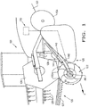
- an agricultural vehicle 100 in the form of a combine harvester 100 which traverses a field in a forward direction, denoted by arrow "F".
- the agricultural vehicle 100 generally includes a chassis 102, wheels 104, and a header 120 connected to the chassis 102.
- the header 120 may be incorporated in any agricultural vehicle such as a combine, a windrower, or any other prime mover that is used for cutting crop material.
- the header 120 may be in the form of any desired header, such as a grain header. As shown in FIG. 1 , the header 120 is in the form of a grain header 120 which generally includes a frame 121, at least one end crop divider(s) 122, having protuberances 123 and fins 124, that is located at the lateral end(s) 125 of the frame 121, a conveyor 126, a cutter bar 127, and a rotating reel 128 with tines 129.
- the header 120 may also include one or more drive units 130 for driving the end crop divider(s) 122 and actuating systems 140 for adjusting the position of the end crop divider(s) 122.
- the header 120 may additionally include various components and systems for the collection and transportation of the crop material; however, such components and systems have been hidden from view for brevity of description.
- a crop divider 122 is positioned at each lateral end 125 of the frame 121 of the header 120.
- the end crop dividers 122 divide and lift the crop material as the agricultural vehicle 100 is moved in the forward direction F.
- the end crop dividers 122 are rotatably connected to the frame 121 and rotate in a rotational direction R1 about an axis of rotation AR.
- the axis of rotation AR may be substantially perpendicular to the forward direction F, plus or minus approximately 15 degrees.
- the end crop dividers 122 may have any desired shape, such as elliptical, trapezoidal, conical, or spherical, which provides positive contact with and effectively divides the crop material.
- the end crop dividers 122 may have a disk-shaped body.
- the disk-shaped-body can be in the form of a prolate spheroid which has been truncated at its left and right sides ( FIG. 2 ).
- the end crop divider 122 may be symmetrical or non-symmetrical.
- the end crop divider 122 may be two-sided as shown, such that the end crop divider 122 is symmetrical, or the end crop divider 122 may be one-sided such that one side has a disked-shape and the other side is substantially flat (not shown).
- the end crop dividers 122 may be composed of any suitable material such as metal, plastic, and/or rubber. In operation, the end crop dividers 122 will lift and divide standing or down crop material. The disked-shape design of the end crop dividers 122 allows the crop material to gently fall inwardly into the header 120 or outwardly away from the header 120.
- the protuberances 123 of the end crop divider 122 perform a raking function in which the protuberances 123 contact and gently lift the crop material.
- the protuberances 123 may be in the form of a plurality of fingers 123 extending outwardly from an outer surface of the end crop divider 122.
- the protuberances 123 may be in the form of ribs, flaps, spikes, nodules, and/or a textured surface.
- the protuberances 123 may be located anywhere along the outer surface of the end crop divider 122.
- the protuberances 123 may be located around the center perimeter of the end crop divider 122.
- the protuberances 123 may be fixedly attached to the end crop dividers 122, or the protuberances 123 may be retractable.
- the fins 124 of the end crop dividers 122 are configured for preventing the crop material from being lodged in between a respective end crop divider 122 and the frame 121 of the header 120.
- the fins 124 may be in the form of grooves or protrusions on the outer surface of the end crop dividers 122 that can effectively contact the crop material.
- the fins 124 of the end crop divider 122 may be located on the sides of the end crop divider 122, and the fins 124 may spiral outwardly from the axis of rotation AR. It should be appreciated that the fins 124 may be located at any desired location on the end crop dividers 122, and the fins 124 may form any desired pattern.
- the drive unit 130 is mounted to the frame 121 and operably connected to the end crop divider 122 such that as the header 120 is moved in the forward direction F, the drive unit 130 rotates each end crop divider 122 about the axis of rotation AR.
- the drive unit 130 can allow for variable speeds in order to better lift and separate the crop material prior to the crop material coming into contact with the reel 128.
- the drive unit 130 may be in the form of a hydraulic drive or an electric drive. Additionally, the drive unit 130 may be in the form of a mechanical driving wheel (not shown).
- the drive unit 130 may include a driving wheel that is rotatably mounted to the frame 121 via a shaft, and the drive wheel may contact the field and the end crop divider 122 as it rotates in order to rotate the end crop divider 122 in the opposite direction.
- the actuating systems 140 may include one or more actuator(s) connected to the frame 121 for adjusting the end crop dividers 122.
- the actuating system 140 includes two actuators 142, 144 for respectively adjusting a respective end crop divider 122.
- the actuating systems 140 may respectively raise, lower, rearwardly move, and/or forwardly move the end crop dividers 122.
- the actuating system 140 may move the end crop dividers 122 in between a stored, retracted position and an active, crop contacting position. It should be appreciated that the actuating systems 140 may include additional actuators for changing the camber angle of the end crop dividers 122.
- FIGS. 4-5 there is shown schematic representations of the drive unit 130 in the form of a hydraulic drive 400 ( FIG. 4 ) and an electric drive 500 ( FIG. 5 ), respectively.
- the agricultural vehicle 100 may include either or both hydraulic and electric drive units 400, 500 in order to drive the end crop dividers 122.
- FIG. 1 shows the drive unit 130 in the form of an electric drive unit 500.
- the hydraulic drive unit 400 generally includes a divider hydraulic motor 402 operably connected to and driving the end crop divider 122 and a control valve 404.
- the divider hydraulic motor 402 is fluidly coupled to a reel hydraulic motor 406 via hydraulic lines 408A, 408B.
- the reel hydraulic motor 406 is attached to and drives the reel 128 in a known manner.
- the control valve 404 may proportionally control the speed of the divider hydraulic motor 402 by controlling the flow of hydraulic fluid in and out of the fluid lines 408A, 408B.
- the divider hydraulic motor 402 and the reel hydraulic motor 406 may rotate in opposite directions. It is conceivable that the divider hydraulic motor 402 may instead be operably connected to a different hydraulic component of the header 120, such as the hydraulic motor of the cutter bar 127, and/or the agricultural vehicle 100.
- the electric drive unit 500 generally includes an electric motor 502 and a controller 504 electrically interconnected via an electrical line 506.
- the electric motor 502 is operably coupled to the end crop divider 122.
- the controller 504 may selectively control the speed of the electric motor 502 in order to speed up or slow down the end crop divider depending upon various crop conditions.
- the controller 504 may be located on the agricultural vehicle 100 or on the header 120. It should be appreciated that the electric motor 502 and the controller 504 may be operably coupled via wireless communication instead of the electrical line 506.
- the controller 504 may be in the form of any desired electronic control unit (ECU), and the controller 504 may be incorporated into existing hardware and/or software of the agricultural vehicle 100.
- the controller 504 may include software code or instructions which are tangibly stored on a tangible computer readable medium.
- the computer readable medium may be in the form of a magnetic medium, e.g., a computer hard drive, an optical medium, e.g., an optical disc, solid-state memory, e.g., flash memory, or other storage media known in the art.
- any of the functionality performed by the controller 504 described herein may be implemented in software code or instructions which are tangibly stored on the tangible computer readable medium.
- the controller 504 may perform any of the functionality described herein.
- software code or “code” used herein refers to any instructions or set of instructions that influence the operation of a computer or controller. They may exist in a computer-executable form, such as machine code, which is the set of instructions and data directly executed by a computer's central processing unit or by a controller, a human-understandable form, such as source code, which may be compiled in order to be executed by a computer's central processing unit or by a controller, or an intermediate form, such as object code, which is produced by a compiler.
- the term "software code” or “code” also includes any human-understandable computer instructions or set of instructions, e.g., a script, that may be executed on the fly with the aid of an interpreter executed by a computer's central processing unit or by a controller.
Landscapes
- Life Sciences & Earth Sciences (AREA)
- Environmental Sciences (AREA)
- Soil Working Implements (AREA)
- Harvester Elements (AREA)
- Harvesting Machines For Specific Crops (AREA)
- Outside Dividers And Delivering Mechanisms For Harvesters (AREA)
- Farming Of Fish And Shellfish (AREA)
- Hydroponics (AREA)
Applications Claiming Priority (1)
| Application Number | Priority Date | Filing Date | Title |
|---|---|---|---|
| US15/901,107 US10687469B2 (en) | 2018-02-21 | 2018-02-21 | Active crop divider for a header |
Publications (2)
| Publication Number | Publication Date |
|---|---|
| EP3530104A1 true EP3530104A1 (fr) | 2019-08-28 |
| EP3530104B1 EP3530104B1 (fr) | 2020-11-18 |
Family
ID=65529322
Family Applications (1)
| Application Number | Title | Priority Date | Filing Date |
|---|---|---|---|
| EP19158171.9A Active EP3530104B1 (fr) | 2018-02-21 | 2019-02-20 | Diviseur de récolte actif pour tête de coupe |
Country Status (5)
| Country | Link |
|---|---|
| US (1) | US10687469B2 (fr) |
| EP (1) | EP3530104B1 (fr) |
| AR (1) | AR114636A1 (fr) |
| AU (1) | AU2019201203B2 (fr) |
| BR (1) | BR102019003443A2 (fr) |
Cited By (1)
| Publication number | Priority date | Publication date | Assignee | Title |
|---|---|---|---|---|
| WO2023180253A1 (fr) | 2022-03-21 | 2023-09-28 | Msr Technology Aps | Appareil de levage et de séparation de fanes |
Citations (5)
| Publication number | Priority date | Publication date | Assignee | Title |
|---|---|---|---|---|
| US393774A (en) * | 1888-12-04 | Divider for harvesting-machines | ||
| CA2287701A1 (fr) * | 1999-10-28 | 2000-02-29 | Merlin Badry | Moissonneuse verticale |
| DE10012056A1 (de) * | 2000-03-14 | 2001-10-11 | Claas Selbstfahr Erntemasch | Hydraulischer Antrieb für ein Einzugsorgan einer Gutaufnahmeeinrichtung |
| US6457302B1 (en) * | 2000-09-08 | 2002-10-01 | Mccrea Thomas Edward | Crop divider with cutter |
| DE10206541A1 (de) * | 2002-02-16 | 2003-08-28 | Deere & Co | Schneidwerk mit rotierendem Halmteiler |
Family Cites Families (38)
| Publication number | Priority date | Publication date | Assignee | Title |
|---|---|---|---|---|
| US3125845A (en) * | 1964-03-24 | Swath gathering mechanism | ||
| US1901099A (en) * | 1930-04-11 | 1933-03-14 | Gleaner Harvester Corp | Cutter mechanism for corn harvesters |
| US2459961A (en) * | 1946-09-23 | 1949-01-25 | Ernest C Pollard | Windrow lifter and turner |
| US2783606A (en) * | 1954-04-09 | 1957-03-05 | Eugene I Wilson | Windrow divider and baler pickup extension |
| US2811006A (en) * | 1954-10-07 | 1957-10-29 | Case Co J I | Divider with rotary vertical cutter |
| US3096604A (en) | 1960-05-31 | 1963-07-09 | Baker Slade Hale | Row crop harvesting apparatus |
| US3331196A (en) | 1964-04-20 | 1967-07-18 | Benjamin M Grant | Harvesting attachment |
| US3456429A (en) * | 1966-02-03 | 1969-07-22 | Us Sugar Corp | Sugarcane harvesting apparatus |
| US3584444A (en) * | 1969-04-30 | 1971-06-15 | Ernest F Sammann | Stalk pickup apparatus for harvesters |
| US3664101A (en) * | 1970-09-11 | 1972-05-23 | Sperry Rand Corp | Crop gathering and converging reel |
| US3678669A (en) * | 1970-09-28 | 1972-07-25 | Henry J Czajkowski | Sweeper attachment for harvesting machinery |
| US3646737A (en) | 1970-10-20 | 1972-03-07 | Benjamin M Grant | Harvesting attachment |
| US3726345A (en) * | 1971-04-26 | 1973-04-10 | Lilliston Corp | Peanut digger shaker inverter |
| US4015667A (en) * | 1975-04-14 | 1977-04-05 | Aldo Ruozi | Cotton stalk and root shredder with re-bedder |
| AU503730B2 (en) * | 1976-08-11 | 1979-09-20 | Massey-Ferguson (Australia) Ltd. | Cane harvester |
| US4182103A (en) * | 1977-07-15 | 1980-01-08 | Mcnutt Darrell A | Window tucker wheels |
| US4346548A (en) * | 1981-04-08 | 1982-08-31 | Atkinson Cecil G | Attachment for a harvester for picking up downed corn stalks |
| US4416334A (en) * | 1982-09-28 | 1983-11-22 | Bouillon Alain M | Potato harvesting apparatus |
| US4476667A (en) * | 1983-04-06 | 1984-10-16 | Donald Moss | Corn pickup attachment for a combine |
| US4524571A (en) | 1983-08-15 | 1985-06-25 | Mak Randall L | Corn harvester machine with mechanism for picking up downed cornstalks and retrieving ears therefrom |
| DE3338812C3 (de) * | 1983-10-26 | 1998-01-29 | Claas Saulgau Gmbh | Kreiselmäher |
| US4584825A (en) * | 1984-02-10 | 1986-04-29 | Atkinson Cecil G | Attachment for a harvester for picking up downed corn stalks |
| DD235411A1 (de) * | 1985-03-20 | 1986-05-07 | Fortschritt Veb K | Schneidwerk zur breitablage |
| US6205752B1 (en) * | 1995-06-26 | 2001-03-27 | New Holland North America, Inc. | Rolling crop guide for disc mower conditioners |
| US6282877B1 (en) * | 1995-06-29 | 2001-09-04 | Pik Rite, Inc. | Fruit and vegetable harvesting apparatus and methods |
| US5878559A (en) | 1996-12-17 | 1999-03-09 | Case Corporation | Corn head snapping and gathering row unit |
| US6032444A (en) * | 1997-06-04 | 2000-03-07 | Hay & Forage Industries | Non-row-sensitive forage harvester |
| CA2280681A1 (fr) * | 1998-08-27 | 2000-02-27 | Macdon Industries Ltd. | Deblayeuse de passage pour la roue porteuse d'un vehicule agricole |
| US6264554B1 (en) * | 1999-10-27 | 2001-07-24 | Merlin Badry | Vertical crop cutting apparatus |
| DE10317469B4 (de) * | 2003-04-16 | 2019-03-07 | Maschinenfabrik Kemper Gmbh & Co. Kg | Erntevorsatz mit einer Stängelheberschnecke |
| CA2525904C (fr) * | 2005-11-03 | 2012-01-03 | Macdon Industries Ltd. | Bec cueilleur de recolte avec diviseur de recolte sur tambour rabatteur-releveur |
| DE102010012686A1 (de) * | 2010-03-24 | 2011-09-29 | Müthing GmbH & Co. KG | Vorrichtung zum Aufrichten von Halmgut |
| WO2012024550A1 (fr) * | 2010-08-19 | 2012-02-23 | Agco Corporation | Vis haveuse pivotante pour bec cueilleur à maïs |
| US8371097B1 (en) * | 2011-09-26 | 2013-02-12 | Cnh America Llc | Baler gathering wheel height adjustment |
| US8590283B2 (en) * | 2012-01-20 | 2013-11-26 | LeRoy Koehn | Downed corn rake |
| WO2013152405A1 (fr) * | 2012-04-09 | 2013-10-17 | Cnh Latin America Ltda | Système de coupe pour machines récolteuses, et machine récolteuse |
| US10021832B2 (en) * | 2015-08-20 | 2018-07-17 | Cnh Industrial America Llc | Row divider having a conveyor for an agricultural harvester |
| CA3000245A1 (fr) * | 2017-04-18 | 2018-10-18 | Agco Corporation | Un bec cueilleur dote d'un disque separateur de recolte |
-
2018
- 2018-02-21 US US15/901,107 patent/US10687469B2/en active Active
-
2019
- 2019-02-19 AR ARP190100413A patent/AR114636A1/es active IP Right Grant
- 2019-02-20 BR BR102019003443A patent/BR102019003443A2/pt active Search and Examination
- 2019-02-20 EP EP19158171.9A patent/EP3530104B1/fr active Active
- 2019-02-20 AU AU2019201203A patent/AU2019201203B2/en active Active
Patent Citations (5)
| Publication number | Priority date | Publication date | Assignee | Title |
|---|---|---|---|---|
| US393774A (en) * | 1888-12-04 | Divider for harvesting-machines | ||
| CA2287701A1 (fr) * | 1999-10-28 | 2000-02-29 | Merlin Badry | Moissonneuse verticale |
| DE10012056A1 (de) * | 2000-03-14 | 2001-10-11 | Claas Selbstfahr Erntemasch | Hydraulischer Antrieb für ein Einzugsorgan einer Gutaufnahmeeinrichtung |
| US6457302B1 (en) * | 2000-09-08 | 2002-10-01 | Mccrea Thomas Edward | Crop divider with cutter |
| DE10206541A1 (de) * | 2002-02-16 | 2003-08-28 | Deere & Co | Schneidwerk mit rotierendem Halmteiler |
Cited By (1)
| Publication number | Priority date | Publication date | Assignee | Title |
|---|---|---|---|---|
| WO2023180253A1 (fr) | 2022-03-21 | 2023-09-28 | Msr Technology Aps | Appareil de levage et de séparation de fanes |
Also Published As
| Publication number | Publication date |
|---|---|
| US20190254232A1 (en) | 2019-08-22 |
| AU2019201203B2 (en) | 2023-07-06 |
| US10687469B2 (en) | 2020-06-23 |
| BR102019003443A2 (pt) | 2019-09-10 |
| EP3530104B1 (fr) | 2020-11-18 |
| AR114636A1 (es) | 2020-09-30 |
| AU2019201203A1 (en) | 2019-09-05 |
Similar Documents
| Publication | Publication Date | Title |
|---|---|---|
| EP3469878B1 (fr) | Centre de roulis pour bras de commande de structure de fixation de moissonneuse | |
| EP3278653A1 (fr) | Machine agricole ayant un organe de coupe pliant | |
| EP3207787B1 (fr) | Système d'ajustement de contre-batteurs de moissonneuse agricole | |
| EP3064052B1 (fr) | Système de came de rouleau agricole | |
| EP3681265B1 (fr) | Table de coupe agricole avec une relation constante entre rabatteur et dispositif de coupe | |
| US11272665B2 (en) | Tined-tube auger | |
| EP3530104B1 (fr) | Diviseur de récolte actif pour tête de coupe | |
| EP3217782B1 (fr) | Moissonneuse agricole comprenant un élévateur tourné | |
| US20220217910A1 (en) | Adjustable reel arm | |
| US7022013B1 (en) | Axial flow combine harvester with adaptable separating unit | |
| EP3090614B1 (fr) | Arbre entraîné avec dissipation de l'énergie cinétique de rotation pour moissonneuse-batteuse | |
| EP1529435B1 (fr) | Moissonneuse-batteuse à écoulement axial avec dispositif de battage adaptable | |
| US10674662B2 (en) | Agricultural windrow chute with rolling edge | |
| EP3821693A1 (fr) | Moissonneuse agricole à réponse proactive au niveau d'humidité d'une culture récoltée | |
| EP1529436B1 (fr) | Moissonneuse-batteuse à écoulement axial avec un dispositif de séparation adaptable | |
| EP3157319B1 (fr) | Dispositif secoueur de paille pour moissonneuse agricole | |
| WO2023212329A1 (fr) | Diviseur de récolte actif pour organe de coupe | |
| EP3479675A1 (fr) | Cage de rotor avec des parois planes pour un véhicule agricole |
Legal Events
| Date | Code | Title | Description |
|---|---|---|---|
| PUAI | Public reference made under article 153(3) epc to a published international application that has entered the european phase |
Free format text: ORIGINAL CODE: 0009012 |
|
| STAA | Information on the status of an ep patent application or granted ep patent |
Free format text: STATUS: THE APPLICATION HAS BEEN PUBLISHED |
|
| AK | Designated contracting states |
Kind code of ref document: A1 Designated state(s): AL AT BE BG CH CY CZ DE DK EE ES FI FR GB GR HR HU IE IS IT LI LT LU LV MC MK MT NL NO PL PT RO RS SE SI SK SM TR |
|
| AX | Request for extension of the european patent |
Extension state: BA ME |
|
| STAA | Information on the status of an ep patent application or granted ep patent |
Free format text: STATUS: REQUEST FOR EXAMINATION WAS MADE |
|
| 17P | Request for examination filed |
Effective date: 20200228 |
|
| RBV | Designated contracting states (corrected) |
Designated state(s): AL AT BE BG CH CY CZ DE DK EE ES FI FR GB GR HR HU IE IS IT LI LT LU LV MC MK MT NL NO PL PT RO RS SE SI SK SM TR |
|
| GRAP | Despatch of communication of intention to grant a patent |
Free format text: ORIGINAL CODE: EPIDOSNIGR1 |
|
| STAA | Information on the status of an ep patent application or granted ep patent |
Free format text: STATUS: GRANT OF PATENT IS INTENDED |
|
| INTG | Intention to grant announced |
Effective date: 20200710 |
|
| GRAS | Grant fee paid |
Free format text: ORIGINAL CODE: EPIDOSNIGR3 |
|
| GRAA | (expected) grant |
Free format text: ORIGINAL CODE: 0009210 |
|
| STAA | Information on the status of an ep patent application or granted ep patent |
Free format text: STATUS: THE PATENT HAS BEEN GRANTED |
|
| AK | Designated contracting states |
Kind code of ref document: B1 Designated state(s): AL AT BE BG CH CY CZ DE DK EE ES FI FR GB GR HR HU IE IS IT LI LT LU LV MC MK MT NL NO PL PT RO RS SE SI SK SM TR |
|
| REG | Reference to a national code |
Ref country code: GB Ref legal event code: FG4D |
|
| REG | Reference to a national code |
Ref country code: CH Ref legal event code: EP |
|
| REG | Reference to a national code |
Ref country code: IE Ref legal event code: FG4D |
|
| REG | Reference to a national code |
Ref country code: DE Ref legal event code: R096 Ref document number: 602019001320 Country of ref document: DE |
|
| REG | Reference to a national code |
Ref country code: AT Ref legal event code: REF Ref document number: 1334727 Country of ref document: AT Kind code of ref document: T Effective date: 20201215 |
|
| REG | Reference to a national code |
Ref country code: AT Ref legal event code: MK05 Ref document number: 1334727 Country of ref document: AT Kind code of ref document: T Effective date: 20201118 |
|
| REG | Reference to a national code |
Ref country code: NL Ref legal event code: MP Effective date: 20201118 |
|
| PG25 | Lapsed in a contracting state [announced via postgrant information from national office to epo] |
Ref country code: RS Free format text: LAPSE BECAUSE OF FAILURE TO SUBMIT A TRANSLATION OF THE DESCRIPTION OR TO PAY THE FEE WITHIN THE PRESCRIBED TIME-LIMIT Effective date: 20201118 Ref country code: PT Free format text: LAPSE BECAUSE OF FAILURE TO SUBMIT A TRANSLATION OF THE DESCRIPTION OR TO PAY THE FEE WITHIN THE PRESCRIBED TIME-LIMIT Effective date: 20210318 Ref country code: FI Free format text: LAPSE BECAUSE OF FAILURE TO SUBMIT A TRANSLATION OF THE DESCRIPTION OR TO PAY THE FEE WITHIN THE PRESCRIBED TIME-LIMIT Effective date: 20201118 Ref country code: NO Free format text: LAPSE BECAUSE OF FAILURE TO SUBMIT A TRANSLATION OF THE DESCRIPTION OR TO PAY THE FEE WITHIN THE PRESCRIBED TIME-LIMIT Effective date: 20210218 Ref country code: GR Free format text: LAPSE BECAUSE OF FAILURE TO SUBMIT A TRANSLATION OF THE DESCRIPTION OR TO PAY THE FEE WITHIN THE PRESCRIBED TIME-LIMIT Effective date: 20210219 |
|
| PG25 | Lapsed in a contracting state [announced via postgrant information from national office to epo] |
Ref country code: BG Free format text: LAPSE BECAUSE OF FAILURE TO SUBMIT A TRANSLATION OF THE DESCRIPTION OR TO PAY THE FEE WITHIN THE PRESCRIBED TIME-LIMIT Effective date: 20210218 Ref country code: LV Free format text: LAPSE BECAUSE OF FAILURE TO SUBMIT A TRANSLATION OF THE DESCRIPTION OR TO PAY THE FEE WITHIN THE PRESCRIBED TIME-LIMIT Effective date: 20201118 Ref country code: IS Free format text: LAPSE BECAUSE OF FAILURE TO SUBMIT A TRANSLATION OF THE DESCRIPTION OR TO PAY THE FEE WITHIN THE PRESCRIBED TIME-LIMIT Effective date: 20210318 Ref country code: PL Free format text: LAPSE BECAUSE OF FAILURE TO SUBMIT A TRANSLATION OF THE DESCRIPTION OR TO PAY THE FEE WITHIN THE PRESCRIBED TIME-LIMIT Effective date: 20201118 Ref country code: SE Free format text: LAPSE BECAUSE OF FAILURE TO SUBMIT A TRANSLATION OF THE DESCRIPTION OR TO PAY THE FEE WITHIN THE PRESCRIBED TIME-LIMIT Effective date: 20201118 Ref country code: AT Free format text: LAPSE BECAUSE OF FAILURE TO SUBMIT A TRANSLATION OF THE DESCRIPTION OR TO PAY THE FEE WITHIN THE PRESCRIBED TIME-LIMIT Effective date: 20201118 |
|
| REG | Reference to a national code |
Ref country code: LT Ref legal event code: MG9D |
|
| PG25 | Lapsed in a contracting state [announced via postgrant information from national office to epo] |
Ref country code: HR Free format text: LAPSE BECAUSE OF FAILURE TO SUBMIT A TRANSLATION OF THE DESCRIPTION OR TO PAY THE FEE WITHIN THE PRESCRIBED TIME-LIMIT Effective date: 20201118 |
|
| PG25 | Lapsed in a contracting state [announced via postgrant information from national office to epo] |
Ref country code: LT Free format text: LAPSE BECAUSE OF FAILURE TO SUBMIT A TRANSLATION OF THE DESCRIPTION OR TO PAY THE FEE WITHIN THE PRESCRIBED TIME-LIMIT Effective date: 20201118 Ref country code: RO Free format text: LAPSE BECAUSE OF FAILURE TO SUBMIT A TRANSLATION OF THE DESCRIPTION OR TO PAY THE FEE WITHIN THE PRESCRIBED TIME-LIMIT Effective date: 20201118 Ref country code: EE Free format text: LAPSE BECAUSE OF FAILURE TO SUBMIT A TRANSLATION OF THE DESCRIPTION OR TO PAY THE FEE WITHIN THE PRESCRIBED TIME-LIMIT Effective date: 20201118 Ref country code: SK Free format text: LAPSE BECAUSE OF FAILURE TO SUBMIT A TRANSLATION OF THE DESCRIPTION OR TO PAY THE FEE WITHIN THE PRESCRIBED TIME-LIMIT Effective date: 20201118 Ref country code: SM Free format text: LAPSE BECAUSE OF FAILURE TO SUBMIT A TRANSLATION OF THE DESCRIPTION OR TO PAY THE FEE WITHIN THE PRESCRIBED TIME-LIMIT Effective date: 20201118 Ref country code: CZ Free format text: LAPSE BECAUSE OF FAILURE TO SUBMIT A TRANSLATION OF THE DESCRIPTION OR TO PAY THE FEE WITHIN THE PRESCRIBED TIME-LIMIT Effective date: 20201118 |
|
| REG | Reference to a national code |
Ref country code: DE Ref legal event code: R097 Ref document number: 602019001320 Country of ref document: DE |
|
| PG25 | Lapsed in a contracting state [announced via postgrant information from national office to epo] |
Ref country code: DK Free format text: LAPSE BECAUSE OF FAILURE TO SUBMIT A TRANSLATION OF THE DESCRIPTION OR TO PAY THE FEE WITHIN THE PRESCRIBED TIME-LIMIT Effective date: 20201118 |
|
| PLBE | No opposition filed within time limit |
Free format text: ORIGINAL CODE: 0009261 |
|
| STAA | Information on the status of an ep patent application or granted ep patent |
Free format text: STATUS: NO OPPOSITION FILED WITHIN TIME LIMIT |
|
| PG25 | Lapsed in a contracting state [announced via postgrant information from national office to epo] |
Ref country code: MC Free format text: LAPSE BECAUSE OF FAILURE TO SUBMIT A TRANSLATION OF THE DESCRIPTION OR TO PAY THE FEE WITHIN THE PRESCRIBED TIME-LIMIT Effective date: 20201118 |
|
| 26N | No opposition filed |
Effective date: 20210819 |
|
| REG | Reference to a national code |
Ref country code: BE Ref legal event code: MM Effective date: 20210228 |
|
| PG25 | Lapsed in a contracting state [announced via postgrant information from national office to epo] |
Ref country code: LU Free format text: LAPSE BECAUSE OF NON-PAYMENT OF DUE FEES Effective date: 20210220 Ref country code: NL Free format text: LAPSE BECAUSE OF FAILURE TO SUBMIT A TRANSLATION OF THE DESCRIPTION OR TO PAY THE FEE WITHIN THE PRESCRIBED TIME-LIMIT Effective date: 20201118 Ref country code: AL Free format text: LAPSE BECAUSE OF FAILURE TO SUBMIT A TRANSLATION OF THE DESCRIPTION OR TO PAY THE FEE WITHIN THE PRESCRIBED TIME-LIMIT Effective date: 20201118 |
|
| PG25 | Lapsed in a contracting state [announced via postgrant information from national office to epo] |
Ref country code: SI Free format text: LAPSE BECAUSE OF FAILURE TO SUBMIT A TRANSLATION OF THE DESCRIPTION OR TO PAY THE FEE WITHIN THE PRESCRIBED TIME-LIMIT Effective date: 20201118 |
|
| PG25 | Lapsed in a contracting state [announced via postgrant information from national office to epo] |
Ref country code: IE Free format text: LAPSE BECAUSE OF NON-PAYMENT OF DUE FEES Effective date: 20210220 Ref country code: ES Free format text: LAPSE BECAUSE OF FAILURE TO SUBMIT A TRANSLATION OF THE DESCRIPTION OR TO PAY THE FEE WITHIN THE PRESCRIBED TIME-LIMIT Effective date: 20201118 |
|
| PG25 | Lapsed in a contracting state [announced via postgrant information from national office to epo] |
Ref country code: IS Free format text: LAPSE BECAUSE OF FAILURE TO SUBMIT A TRANSLATION OF THE DESCRIPTION OR TO PAY THE FEE WITHIN THE PRESCRIBED TIME-LIMIT Effective date: 20210318 |
|
| PG25 | Lapsed in a contracting state [announced via postgrant information from national office to epo] |
Ref country code: BE Free format text: LAPSE BECAUSE OF NON-PAYMENT OF DUE FEES Effective date: 20210228 |
|
| REG | Reference to a national code |
Ref country code: CH Ref legal event code: PL |
|
| PG25 | Lapsed in a contracting state [announced via postgrant information from national office to epo] |
Ref country code: LI Free format text: LAPSE BECAUSE OF NON-PAYMENT OF DUE FEES Effective date: 20220228 Ref country code: CH Free format text: LAPSE BECAUSE OF NON-PAYMENT OF DUE FEES Effective date: 20220228 |
|
| PGFP | Annual fee paid to national office [announced via postgrant information from national office to epo] |
Ref country code: FR Payment date: 20230222 Year of fee payment: 5 |
|
| PGFP | Annual fee paid to national office [announced via postgrant information from national office to epo] |
Ref country code: IT Payment date: 20230210 Year of fee payment: 5 Ref country code: GB Payment date: 20230220 Year of fee payment: 5 Ref country code: DE Payment date: 20230223 Year of fee payment: 5 |
|
| PG25 | Lapsed in a contracting state [announced via postgrant information from national office to epo] |
Ref country code: CY Free format text: LAPSE BECAUSE OF FAILURE TO SUBMIT A TRANSLATION OF THE DESCRIPTION OR TO PAY THE FEE WITHIN THE PRESCRIBED TIME-LIMIT Effective date: 20201118 |
|
| PG25 | Lapsed in a contracting state [announced via postgrant information from national office to epo] |
Ref country code: HU Free format text: LAPSE BECAUSE OF FAILURE TO SUBMIT A TRANSLATION OF THE DESCRIPTION OR TO PAY THE FEE WITHIN THE PRESCRIBED TIME-LIMIT; INVALID AB INITIO Effective date: 20190220 |
|
| PG25 | Lapsed in a contracting state [announced via postgrant information from national office to epo] |
Ref country code: MK Free format text: LAPSE BECAUSE OF FAILURE TO SUBMIT A TRANSLATION OF THE DESCRIPTION OR TO PAY THE FEE WITHIN THE PRESCRIBED TIME-LIMIT Effective date: 20201118 |
|
| PGFP | Annual fee paid to national office [announced via postgrant information from national office to epo] |
Ref country code: DE Payment date: 20240228 Year of fee payment: 6 Ref country code: GB Payment date: 20240221 Year of fee payment: 6 |