EP3529925B1 - Verfahren und vorrichtung zur optimierung der funkfrequenzleistung eines fm-hörfunksenders - Google Patents
Verfahren und vorrichtung zur optimierung der funkfrequenzleistung eines fm-hörfunksenders Download PDFInfo
- Publication number
- EP3529925B1 EP3529925B1 EP17797679.2A EP17797679A EP3529925B1 EP 3529925 B1 EP3529925 B1 EP 3529925B1 EP 17797679 A EP17797679 A EP 17797679A EP 3529925 B1 EP3529925 B1 EP 3529925B1
- Authority
- EP
- European Patent Office
- Prior art keywords
- power
- signal
- curve
- control
- servo
- Prior art date
- Legal status (The legal status is an assumption and is not a legal conclusion. Google has not performed a legal analysis and makes no representation as to the accuracy of the status listed.)
- Active
Links
Images


Classifications
-
- H—ELECTRICITY
- H04—ELECTRIC COMMUNICATION TECHNIQUE
- H04H—BROADCAST COMMUNICATION
- H04H20/00—Arrangements for broadcast or for distribution combined with broadcast
- H04H20/42—Arrangements for resource management
- H04H20/423—Transmitter side
-
- H—ELECTRICITY
- H04—ELECTRIC COMMUNICATION TECHNIQUE
- H04H—BROADCAST COMMUNICATION
- H04H20/00—Arrangements for broadcast or for distribution combined with broadcast
- H04H20/44—Arrangements characterised by circuits or components specially adapted for broadcast
-
- H—ELECTRICITY
- H04—ELECTRIC COMMUNICATION TECHNIQUE
- H04H—BROADCAST COMMUNICATION
- H04H2201/00—Aspects of broadcast communication
- H04H2201/10—Aspects of broadcast communication characterised by the type of broadcast system
- H04H2201/18—Aspects of broadcast communication characterised by the type of broadcast system in band on channel [IBOC]
- H04H2201/183—FM digital or hybrid
Definitions
- the present invention relates to the optimization of RF power of FM broadcast transmitters and proposes a method and device for managing this RF power as a function of the content of the modulating signal, in order to reduce the electrical power consumed by the transmitter and/or 'optimize the radio service area covered by the transmitter.
- FM (Modulated Frequency) broadcasting, band II constitutes to date one of the rare standards adopted by the entire planet, with a few variations.
- radio frequency (RF) stages benefit from active components allowing the implementation of large amplitude automatic gain control (AGC) before saturation; the signal to noise ratio (S/N) is thus almost constant on the receiver's audio outputs, up to the receiver's operating limit.
- AGC automatic gain control
- the radio environment of the FM band has deteriorated over the years: multiplication of broadcasting networks and therefore of channel occupancy, degradation of protection between adjacent channels attributable to compression tools, "noise" general increase in radio frequency attributable to the appearance of GSM networks and polluting industrial equipment.
- the patent US 9,195,094 B1 describes a device and a method for adapting the power of a transmitter according to the behavior of the receiver (vehicle radio) and its RF environment. The device thereby selects the appropriate radio signal level to overcome interference from co-channel, and/or adjacent channel users and other noise components at the radio frequency of the transmitter of the FM modulator device.
- the calculation of the probability of interference, image frequencies, jamming and intermodulation, carried out prior to the validation of a frequency plan constitutes on the one hand one of the most delicate points to carry out and on the other hand on the other hand, a key to the success of a balanced, homogeneous network free of incompatibility in terms of frequencies, provided that the calculated figures are verified in the field.
- FM transmitters are made up of different power blocks capable of providing up to 10kW RF, or even more.
- FM modulation causes an excursion of the nominal frequency and not a variation of the RF power. This means that the output power remains perfectly stable, with or without a modulating sound signal.
- the efficiency of a 10kW transmitter is around 75%, or an electrical power consumed of around 13.3kW, 24 hours a day, 365 days a year. Added to consumption indirect, (forced ventilation of bays, air conditioning of premises), the total consumption of an excellent FM transmitter providing RF power of 10kW can be estimated at 15kW.
- the present invention relates the two observations mentioned above:
- the excess quality is estimated at around 10dB in the link budget of a current FM broadcasting network, compared to ITU-R recommendations and station managers or broadcast operators wish to achieve economies of scale in the operation of their equipment.
- the invention aims to optimize the power of an FM transmitter by producing a device which controls the RF output power of the transmitter as a function of the signal-to-apparent audio noise ratio, predicted upon reception of the signal.
- the apparent signal-to-noise ratio can be defined as follows: it is the level of non-essential audible noise (all that is not contained in the useful sound program) in relation to the level of the useful signal (the sound program).
- the perception of noise is based in particular on the masking effect according to which the denser the sound signal, the more it masks noises and sounds of lower amplitudes.
- FM thanks to the presence of audio processing tools, we achieve levels of density, energy and power of the modulating signal never before practiced in other areas of sound broadcasting.
- the dynamics is thus inscribed between two immutable limits of a few decibels of amplitude, the upper threshold of which is always located at the maximum of the excursion authorized.
- the masking effect is then maximum, with respect to non-essential and unwanted noise likely to be part of the overall signal demodulated by the receiver.
- the ear is also insensitive to sounds produced after the disappearance of the masking sound, for durations varying between 50 and 100ms, depending on the frequency and amplitude of the masking and masked sounds.
- This post-masking effect is used here to carry out part of the calculations and determine part of the actions to be carried out via the device of the invention.
- the present invention provides a method for optimizing the transmission power of an FM broadcast transmitter as defined in claim 1.
- the invention therefore proposes a method for optimizing the radio frequency power emitted, therefore directly the electrical power consumed by an FM broadcast transmitter.
- the means for generating electrical signals for controlling the power of the transmitter by digital/analog conversion are connected to a control stage of the driver stages of the amplifier.
- the means for generating electrical signals for controlling the power of the transmitter by digital/analog conversion can be connected to the FM carrier generation stage and/or to a block control stage. power of the amplifier and/or their power supplies.
- the principle of the present invention is to provide a method and a device for controlling the RF output power of a transmitter as a function of the signal-to-apparent audio noise ratio, predicted upon reception of the signal.
- the apparent signal-to-noise ratio can be defined as follows: it is the level of audible non-essential noise, i.e. everything that is not contained in the useful sound program, in relation to the level of the useful signal which is the sound program.
- the denser the sound signal the more it masks noise and sounds of lower amplitudes.
- FM thanks to the presence of audio processing tools, we achieve levels of density of the Multiplex modulating signal (stereophonic composite signal compatible with monophonic receivers and additional signals of the subcarriers and data associated with the program) never before practiced in other areas of sound diffusion.
- the dynamics is thus inscribed between two immutable limits of a few decibels of amplitude, the upper threshold of which is always located at the maximum of the authorized excursion.
- the masking effect is then maximum, with respect to non-essential and unwanted noise likely to be part of the overall signal demodulated by the receiver.
- the ear is also insensitive to sounds produced after the disappearance of the masking sound, for durations varying between 50 and 100ms, depending on the frequency and amplitude of the masking and masked sounds.
- the present invention uses this post-masking effect to perform calculations and determine the actions to be carried out via the servo device of the invention.
- the invention uses the non-linear acoustic characteristics of the human auditory system, in particular the general masking effect observed in the audible frequency band and the effects produced by the sound processing systems implemented in the audio channels. FM broadcast.
- the invention can include an analysis of the modulating signal on criteria of frequency, amplitude, dynamics, spectral distribution and calculation of energy. instantaneous and average, of the power of the sound signals composing the modulating signal such as M signal, S signal, Pilot signal and optionally additional signals composing the modulating signal such as subcarrier(s), data, stereophonic complementary signals, etc. ...
- the invention will then include a control of the RF power of the transmitter as a function of said analysis and said resulting calculations by means of a control signal.
- Loudness is a term designating in the context of the invention the sound strength of the signal as used in the standards and not the physiological correction filter comprising a curve modeling the perception of sound intensity of the human ear.
- the invention provides a series of algorithms which combine measurements resulting from the real-time observation of one or more of these parameters to obtain a resulting signal representative of the variation in the apparent signal/noise ratio perceived by the listener.
- This resulting signal is used to control the RF power of the transmitter, by acting either on the RF excitation control, or on the controls of the RF amplifiers, or on the power supply voltages of the power stages, or on a mix of two or three of these actions.
- This control of the RF output power of the transmitter then makes it possible to obtain a constant signal/apparent noise ratio for the listener, whatever the type of program.
- the RF power of the transmitter is increased in the proportion calculated in the series of algorithms, to tend towards a constant signal to apparent noise ratio.
- the RF power of the transmitter is reduced in the proportion calculated in the series of algorithms, to tend towards a signal-to-noise ratio constant apparent which saves energy at the transmitter.
- the method allows the management of an average RF power lower than the maximum power of the transmitter, therefore a proportional reduction in the energy consumption of the transmission system while by increasing listening comfort during periods when the signal-to-noise ratio is predicted to be potentially degraded.
- Operator instructions make it possible to set the minimum and maximum power limits authorized by the operator following technical or regulatory recommendations.
- This global modulating signal has already undergone the various treatments desired by the station operator. It is therefore the exact reflection of the modulated signal broadcast by the transmitter.
- the device of the invention comprises means for processing the signals taken and/or derived in the form of specific algorithms following a particular methodology.
- the minimum duration of a sample is determined, for example from 10 to 100 ms and preferably around 50 ms.
- n*d 0.5 to 2 seconds and for example over approximately 1 second.
- P EPM the principle of the sliding second by adding new recurrence samples d. It is therefore possible to obtain a result P EPM each duration d, for example each 50ms, obtained on an average observation of a sliding duration of n*d, for example one second, except for the first calculation period n*d .
- OdBr reference of P EPM corresponds to a permanent signal of frequency 1kHz causing an excursion or a frequency deviation of ⁇ 19kHz which is accepted and recommended by the ITU-R in the calculation of the MPX power reference.
- the data making it possible to calculate the energy/power P EPM are gathered in a calculation system, for example a microprocessor or microcontroller and its associated program and data memory.
- the energy/power P EPM range of between -3dBr and +10dBr is taken into account.
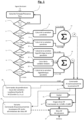
- a step 1 of calculating the energy/power is carried out P EPM .
- a first test 2 defines that below a limit of -3dBr, the system is deactivated.
- the variation of the RF power is fixed for example between -3.5dB and +1.5dB. From 0dB to -3.5dB is a decrease in RF power and from 0dB to +1.5dB is an increase in RF power.
- a second test 3 defines that for P EPM between - 3dBr and -0dBr a calculation 8 of the control, in this case an increase in the RF power is possible from +1.5dB to +0.5dB.
- a third test 4 defines that for P EPM between OdBr and +3dBr a calculation 9 of the control, in this case always an increase, of the RF power is possible from +0.5dB to 0dB.
- a sixth test 7 defines that for P EPM calculated between +7dBr and +10dBr a calculation 12 of weighted logarithmic type variation of the servo, always an attenuation, of the RF power is carried out.
- This data is also introduced into the calculation system.
- the results of these calculations are summed for the possible increases 13 and for the possible attenuations 14 and provide the data for the generation of the control signal of the driver stage at the level of a digital/analog converter 15.
- This pilot control signal controlling the RF output power of the transmitter power stage, via the driver stage 16 and/or the exciter 20 and/or the power blocks 17 and/or the power supplies 19 .
- a first variant 18 detailed in figure 2 consists of taking into account the level of Loudness, which translates into sound force, a numerical model representative of sound energy according to the sound level and the characteristics of the ear as defined in the EBU-R128 recommendation and the methodology ITU-R BS.1770-2 and its annexes.
- a first step 121 consists of calculating the Loudness level.
- a first test 122 determines a maximum Loudness level at -43 LU beyond which no correction is made.
- a second variant corresponding to the Figure 3 consists of taking into account the signal M, the Left (G) + Right (R) sound component of the useful signal.
- the signal M is extracted from the multiplex signal or from the transport or retransmission network in step 201.
- a Fourier transformation FFT 202 we sample the signal to obtain the entire spectrum of M for example on the 20Hz-15kHz spectrum then we carry out a Fourier transformation FFT 202 and we define four groups of frequencies 203a, 203b, 203c, 203d. Then, a calculation module 204 rectifies the 2 half-waves and integrates the signal over a period of around 50 ms to obtain a curve representative of the envelope of the peaks of the signal M.
- an FFT is carried out on the 40Hz-15kHz band.
- the principle being to make an evaluation of the value of the instantaneous average amplitude over frequency bands.
- the curves are advantageously produced by octave or by 1/3 of an octave. In the example below the curves are made over octave ranges.
- the values from the tests are used in a module 208 giving a weighting control signal for the servo control of the RF power.
- a programmed delay of the order of 250ms would make it possible to predict the exact level of control of the RF power and to act on the power adjustment command before observing the variation in the energy/power of the modulating signal. This would phase the action exactly at the desired moment and not with at least a few tens to hundreds of ms of delay attributable to the analysis of the situation and the calculations necessary for decision-making.
- the signals calculated with or without the proposed variants are calibrated and adapted to the transmitter power adjustment control bodies, via the RF driver stage and/or the FM carrier generation stage (exciter) and /or the control stages of the power blocks and/or the power supplies of the RF power stages.
- the implementation of the invention does not require structural modification of modern transmitters. All of the required signals and commands are easily accessible and already used in the standard management of an FM transmitter.
- the device for sampling electrical signals, calculating and generating electrical signals within the transmitter in the form of an additional module comprising a hardware acquisition and calculation platform, itself supporting the embedded software of the application comprising the signal processing units and the algorithms for decisions and actions concerning the control and control of the RF power of transmitter output.
- THE figures 7 And 8 represent block diagrams of FM transmitters equipped with modules of the invention and its variants.
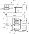
- FIG. 7 a transmitter block diagram comprising the invention in the form of a processing module 303.
- the transmitter includes audio inputs supplying an audio processing block 301 comprising a stereo encoder, possibly an RDS encoder and multi-band audio processing.
- the signal leaving the audio processing block is a multiplex signal 312 which enters an FM modulator/exciter (carrier generator) 302 amplified by a driver stage 305 and RF power blocks 307 connected to a power supply 306 and of which the outputs are added 308 to deliver an RF output signal of power 313.
- an FM modulator/exciter carrier generator
- the processing module 303 receives a setpoint 304 in which the correction parameters chosen by the operator are defined and in particular correction rate, application frequencies, presets depending on the type of sound program, definition of the minimum RF power limits/ maximum.... It also receives the multiplex signal 312. The processing module performs the necessary calculations to generate a control signal 310 for the control stages also called driver 305.
- the transmitter includes audio inputs supplying an audio processing block 301 comprising a stereo encoder, possibly an RDS encoder and multi-band audio processing.
- This audio signal can arrive within the transmitter via other very different routes, for example: wired audio, radio beams, satellite, analog or digital mode, via Intranet or Ethernet computer networks, via a fully or fully demodulating retransmission receiver. partially the signal....
- the signal leaving the audio processing block is a multiplex signal 312 which enters a modulator/exciter or generator module of the FM carrier 302.
- the multiplex signal 302 passes into a line module at delay 401 controlled by the processing module 404.
- the output signal of the FM modulator is amplified by a driver stage 305 and RF power blocks 307 connected to a power supply 406.
- the outputs of the delay blocks 307 power are added 308 to deliver an RF output signal of power 313.
- the processing module 404 also receives a setpoint 304 in which the correction parameters chosen by the operator are defined and in particular the correction rate, the application frequencies, the presets according to the category of sound program, the definition minimum/maximum RF power terminals.... It receives the multiplex signal 312 and a sampling 311 of the RF power output signal by means of a probe 309 and, depending on the additional modules which are integrated, the processing 404 receives the audio signal L+R 403 and/or the modulation signal M 402.
- the processing module performs the necessary calculations to generate a control signal 410 for the control stages (driver) 305 and possibly the control of the line delay 401 and/or control 412 of the exciter 302 or generator of the FM carrier and/or control 411 of the RF power blocks 307 and/or control 405 of the power supply 406 of the power blocks.
- the module 404 calculates the average RF power of the transmitter over a duration T and weights the control signal of the module 404c to maintain the latter within the defined limits by instructions 304 which constitutes a control for the power of the transmitter.
- the desired objective is of course to reduce the operating cost of the transmitter or of all of several networks of transmitters, without notable and audible alteration of the sound program received by the listener, but also to maintain comfort optimum listening experience when the nature of the program does not allow, in theory, a sufficient signal/apparent noise ratio, in difficult reception areas.
- This management of the RF Power by the modulating signal makes it possible to evaluate the equivalent efficiency of a transmitter as a function of the calculated energy/power P EPM of the modulating signal, of the Loudness level according to a first variant, of the variation of the level depending on the frequency of the left and right primary signals according to a second variant, with or without the insertion of the device and the method of the invention.
- the method of the invention will in particular provide for sampling an electrical signal indicating the real RF output power of the transmitter provided by a probe for measuring the direct and reflected RF powers at the output of the transmitter.
- the analysis of the modulating signal can in particular take into account at least the constituent signals of the sound signal, namely on the one hand the left and right audio channels whatever their level of processing, transport or coding, and on the other hand the signals ancillary to the main sound signal: subcarrier(s), data associated with the program, secondary programs and any form of signal participating in the constitution of the signal modulating the transmitter, often called Multiplex signal.
- the analyzes carried out are of frequency order on the spectrum of the modulating signal and of temporal order with a quantification of the dynamics, the amplitude, the duration of the presence of the signals.
- the calculation of the energy of the modulating signal is carried out by processing the data resulting from the analyzes carried out on the different components of the modulating signal.
- the calculation takes into account a method of distribution of the signal samples and/or a direct calculation method, by taking into account the sum of the squares of the samples.
- the RF power control signal can then result from a series of algorithms and calculations making it possible to complete a control curve whose variation characteristics (typology, shape) are determined according to the energy ranges/ power and designated categories of programs.
- the distribution of the curves is carried out over frequency ranges such as thirds of octaves, octaves or pairs of consecutive octaves.
- the distribution is made over 4 curves in a 20Hz-20kHz band or more precisely four curves in pairs of octaves on the 40Hz-10.24kHz band considering that the 20Hz-40Hz and 10kHz-20kHz ranges have little contribution to the signal energy.
- the weighting is adapted according to the differences between the curves.
- the invention can include the insertion of a programmed broadcast delay intended to compensate for the calculation time of the servo signal , the time for calculating the RF power control level and re-phasing the RF power control signal with the broadcast sound signal.
- the method of the invention comprises a calculation of the energy/power (P EPM ) of the modulating signal produced according to a method of distributing sound samples within a table of levels of excursion and/or following a method of summing the squares of the sample values.
- the method comprises the setting of conditions for developing the RF power control signal resulting from the calculations of P EPM , expressed in dBr, and the determination of a correction scale as a function of the energy/power of the representative signal, said scale comprising the association of a series of consecutive ranges of increasing levels of the representative signal with a series of consecutive decreasing correction levels of the RF power of the transmitter by the servo-control signal, scale for which for low levels the servo-control effects an increase in the RF power of the transmitter and for high levels the servo-control effects a reduction in the RF power of the transmitter.
- the invention is not limited to the examples described and can combine several of the compensation methods described to either optimize the power according to the sound content of the program, or maximize the emitted power always according to the sound content.
Landscapes
- Engineering & Computer Science (AREA)
- Signal Processing (AREA)
- Business, Economics & Management (AREA)
- General Business, Economics & Management (AREA)
- Transmitters (AREA)
Claims (22)
- Verfahren zum Optimieren der Sendeleistung eines FM-Hörfunksenders, welches die Schritte beinhaltet zum:- Entnehmen eines modulierenden Signals, welches repräsentativ für den durch den FM-Hörfunksender auszustrahlenden Audio-Inhalt ist;- fortlaufenden Berechnen von konstituierenden Parametern des repräsentativen modulierenden Signals, aus der Leistung der Schallsignale, aus denen sich das modulierende Signal zusammensetzt, Frequenz, Amplitude Dynamik, zeitlicher Verteilung, und Energie;- fortlaufenden Analysieren der Parameter im Vergleich zu einer Modellierung von psychoakustischen Daten;- Erzeugen eines Regelsignals für die Leistung des Senders in Abhängigkeit von den Ergebnissen der Analyse, und von fortlaufenden Berechnungen basierend auf den konstituierenden Parametern und den psychoakustischen Daten;- Steuern der RF-Leistung des Senders anhand des Regelsignals (310), sodass es Folgendes beinhaltet:und wobei die Resultierende aus diesen Berechnungen (13, 14) ein Befehlssignal für die Regelung der RF-Ausgangsleistung des Senders bildet.- die Festlegung von Ausarbeitungsbedingungen für das Regelsignal der RF-Leistung, welche aus den Berechnungen der Energie/Leistung PEPM hervorgeht, ausgedrückt in dBr, und die Bestimmung einer Korrekturskala in Abhängigkeit von der Energie/Leistung des repräsentativen Signals, wobei die Skala die Verknüpfung einer Reihe von aufeinanderfolgenden Bereichen von ansteigenden Stufen des repräsentativen Signals mit einer Reihe von aufeinanderfolgenden abnehmenden Korrekturstufen der RF-Leistung des Senders durch das Regelsignal beinhaltet, wobei die Regelung in der Skala bei schwachen Stufen eine Erhöhung der RF-Leistung des Senders durchführt, und die Regelung bei starken Stufen eine Verringerung der RF-Leistung des Senders durchführt, und- die Festlegung von Ausarbeitungsbedingungen für das Regelsignal der Erhöhung der RF-Leistung durch Einrichten eines Wertes für die Energie/Leistung PEPM (1) des repräsentativen Signals und die RF-Leistung PRF, sodass:a) für eine PEPM größer als -3dBr und kleiner als OdBr (3), Berechnen der Regelung (8) der RF-Leistung von +1,5dB bis 0, 5dB,b) für eine PEPM größer als OdBr und kleiner als +3dBr (4), Berechnen der Regelung (8) der RF-Leistung von +0,5dB bis OdB,- die Festlegung von Ausarbeitungsbedingungen für das Regelsignal der Abschwächung der RF-Leistung durch Einrichten einer nicht linearen Kurve, Kurve A, erste Kurve genannt, zwischen der Variation der Energie/Leistung PEPM (1) des repräsentativen Signals und der RF-Leistung PRF, sodass für PEPM = +3dBr Odb an Erhöhung/Abschwächung von RF anstehen, und für PEPM größer oder gleich 10dBr 3,5db an Abschwächung von RF anstehen;- eine Bestimmung der Form der Variation (5, 6, 7,):a) Variation der gewichteten logarithmischen Art (10), und inverse Variation der Regelung der RF-Leistung für eine berechnete Energie/Leistung PEPM zwischen +3dBr und +5dBr,b) Variation der linearen Art (11) der Regelung der RF-Leistung für eine berechnete Energie/Leistung PEPM zwischen +5dBr und +7dBr,c) Variation der gewichteten logarithmischen Art (12) der Regelung der RF-Leistung für eine berechnete Energie/Leistung PEPM zwischen +7dBr und +10dBr;
- Verfahren nach Anspruch 1, wobei das repräsentative modulierende Signal aus dem Audio-Signal, dem Multiplex-Signal MPX, dem Signal M "Mono L+R", dem Signal M "Mono L+R" +S "Stereo L-R" ausgewählt ist.
- Verfahren nach den Ansprüchen 1 oder 2, welches eine Berechnung der Energie/Leistung PEPM des modulierenden Signals beinhaltet, welche entsprechend einem Verfahren zur Verteilung der Schallproben innerhalb einer Tabelle für die Abweichungsstufen und/oder entsprechend einem Verfahren zur Summierung der Quadrate der Probenwerte erfolgt.
- Verfahren nach Anspruch 3, welches für die Berechnung der Energie/Leistung PEPM die Auswahl einer Mindestprobendauer (d), die Berechnung einer Endsumme der Stufe einer jeden Beobachtung nach n*d Proben und eine Berechnung der Energie/Leistung PEPM entsprechend dem Prinzip der gleitenden Sekunde durch Hinzufügen der neuen Wiederholungsproben (d. umfasst.
- Verfahren nach einem der Ansprüche 1 bis 4, welches die Schaffung einer Klassifizierung nach Programmkategorien beinhaltet, die durch die Ergebnisse einer Spektralanalyse des den Sender modulierenden Schallsignals und/oder durch die Art der decodierten verknüpften Daten aus dem RDS Radio-Data-System-Raster, welches das Schallprogramm begleitet, und der Anwendung einer Korrektur der RF-Leistung basierend auf der Art von Kategorie erhalten wird.
- Verfahren nach Anspruch 1, wobei die Referenz OdBr der Energie/Leistung PEPM des modulierenden Signals einem Dauersignal mit einer Frequenz von 1kHz entspricht, welches zu einer Abweichung oder Ablenkung einer Frequenz um ±19kHz führt.
- Verfahren nach Anspruch 1 oder 6, wobei nur der Bereich der Energie/Leistung PEPM des modulierenden Signals von mehr als -3dBr berücksichtigt wird.
- Verfahren nach Anspruch 1, 6 oder 7, wobei die Regelung der RF-Leistung bei -3,5dB bis +1,5dB liegt.
- Verfahren nach einem der Ansprüche 1, 6, 7 oder 8, wobei eine nicht lineare Kurve, Kurve B, zweite Kurve genannt, aus Berechnungsdaten der Loudness-Funktion eingerichtet wird, indem als Referenz die im Rundfunk zulässige Loudness-Stufe, nämlich -23LUFS mit einer Dynamik in der Größenordnung von 20LU verwendet wird, und die folgenden Schritte beinhaltend:- Berechnen der Loudness-Funktion (121);- Bestimmen (122, 123, 124, 125) der Form der Variation der zweiten Kurve, Kurve B, in Abhängigkeit von der Loudness-Funktion;- Erstellen (129, 130) eines Gewichtungssignals für die erste Kurve, Kurve A, zum Steuern einer Treiberstufe des Verstärkers und Regeln der RF-Ausgangsleistung des Senders aus der Resultierenden dieser Berechnungen, mit den folgenden Schritten:- Berechnen der Loudness-Funktion (121) für ein Messergebnis der Energie/Leistung PEPM (Kurve A) zum Zeitpunkt T,- Berechnen des Wertes der RF-Regelung in dB V1 aus der ersten Kurve, Kurve A, und des Wertes V2 aus der berechneten Gewichtung in % entsprechend der zweiten Kurve, Kurve B,- Berechnen des gewichteten Wertes V3 der Regelung der in die Leistungsstufen einzubringenden RF-Leistung gemäß der Formel:

- Verfahren nach Anspruch 9, wobei die Form der zweiten Kurve entsprechend den folgenden Regeln berechnet wird:a - Variation der gewichteten logarithmischen Art (126), und inverse Variation der Regelung der RF-Leistung für eine berechnete Loudness-Funktion zwischen -43LU und -37LU;b - Variation der linearen Art (127) der Regelung der RF-Leistung für eine berechnete Loudness zwischen -37LU und -30LU;c - Variation der gewichteten logarithmischen Art (128) der Regelung der RF-Leistung für eine berechnete Loudness-Funktion zwischen -30LU und -23LU;
- Verfahren nach einem der Ansprüche 1, und 6 bis 10, welche eine Extrahierung (201) des Signals L+R M aus dem Multiplex-Signal, eine Probennahme dieses Signals zum Erhalten des Spektrums des Signals L+R (202), ein Aufrichten der Halbschwingungen, und eine Integration (204) dieses Signals über einen Zeitraum d1, um eine repräsentative Kurve für die Hülle der Spitzen des Signals L+R zu erhalten, ein Einrichten einer Kurve, Kurve C, dritte Kurve genannt, einer linearen Variation mit der Hülle des Signals L+R M; und eine Gewichtung (208) der Regelung der RF-Leistung aus der ersten Kurve, Kurve A, mithilfe der Daten der dritten Kurve, Kurve C, mit den folgenden Bedingungen beinhaltet:- im Falle einer als rasch bestimmten Variation, oder geringer als etwa 300ms der dritten Kurve, Kurve C nach 0, wird die Regelungsrate der RF-Leistung verringert;- die als rasch bestimmten Variationen der Erhöhung der Hülle werden bei der Gewichtung nicht berücksichtigt, sofern diese letztere kleiner als 0,5dB ist.
- Verfahren nach einem der vorstehenden Ansprüche, Folgendes beinhaltend:- das Durchführen einer Fast Fourier-Transformation FFT (202) in einem Nutzsignalband mit dem Signal L+R M, welche die Bewertung des Wertes der momentanen mittleren Amplitude beinhaltet, nach Frequenzbereichen;- das Einrichten einer Reihe von zusätzlichen Kurven genannten Kurven C01, C02, C03, ..., C0n für die aufeinanderfolgenden ansteigenden Frequenzbereiche aus der FFT, durch Berechnen der Hülle der Amplitude für jeden Bereich in Abhängigkeit von einer Referenzzeit für die Integration;- eine Quantifizierung der Energiedifferenz oder Energiedichte zwischen jeder Hülle einer jeden so eingerichteten Kurve;- das Einrichten eines Gewichtungsalgorithmus für die Regelung der RF-Leistung (205, 206, 207).
- Verfahren nach Anspruch 12, wobei der Gewichtungsalgorithmus gemäß den folgenden Regeln erstellt wird:- Keine Gewichtung, wenn die Amplitude der aufeinanderfolgenden Frequenzbereichskurven in Abhängigkeit vom ansteigenden Rang der Kurven abnimmt;- Gewichtung um -5% bis -25% der Regelung der RF-Leistung, wenn die Amplitudendifferenz zwischen den ansteigenden Frequenzbereichskurven abnimmt,- Maximale Gewichtung um -25% bis -50% der Regelung der RF-Leistung, wenn die Amplitude der Kurven geringeren Ranges kleiner oder gleich der Amplitude der Kurven höheren Ranges ist;wobei das so bestimmte Gewichtungssignal zum Bestandteil des Regelungsbefehls für die Leistungsstufen des Senders (208) wird.
- Verfahren nach Anspruch 12 oder 13, wobei die zusätzlichen Kurven in Frequenzbändern erstellt werden, die aufeinanderfolgende Oktav-Terzen oder Oktaven zusammenfassen, wobei die Integrationszeit für die Berechnung der Hülle der Amplitude größer oder gleich dem Kehrwert der niedrigsten Frequenz des Frequenzbandes für jede Kurve ist.
- Verfahren nach Anspruch 14, welches die folgende Verteilung der zusätzlichen Kurven beinhaltet:eine Kurve C01 für die Summe der Oktaven 40Hz-80Hz + 80Hz-160Hz, oder 20Hz-40Hz + 40Hz-80Hz gemäß dem Programmtyp, mit einer Integrationszeit größer oder gleich I/F01, wobei F01 die niedrigste Frequenz in der Frequenzspanne ist, die für diese Kurve berücksichtigt wird;eine Kurve C02 für die Summe der beiden folgenden Oktaven der Oktaven 160Hz-320Hz + 320Hz-640Hz, oder 80Hz-160Hz + 160Hz-320Hz, wenn die erste Kurve nach unten versetzt ist, mit einer Integrationszeit größer oder gleich 1/F02, wobei F02 die niedrigste Frequenz in der Frequenzspanne ist, die für diese Kurve berücksichtigt wird;eine Kurve C03 für die Summe der Oktaven 640Hz-1,28kHz + 1,28kHz-2,56kHz, oder 320Hz-640Hz + 640Hz-1,28Hz, für eine nach unten versetzte untere Kurve, mit einer Integrationszeit größer oder gleich 1/F03, wobei F03 die niedrigste Frequenz in der Frequenzspanne ist, die für diese Kurve berücksichtigt wird.
- Verfahren nach Anspruch 15, wobei die Verteilung zusätzlicher Kurven auch Folgendes beinhaltet:eine Kurve C04 für die Summe der Oktaven 2,56kHz-5,12kHz + 5,12 kHz-10,24kHz oder 1,28kHz-2,56kHz + 2,56kHz-5,12kHz + 5,12kHz-10,24kHz, für eine nach unten versetzte untere Kurve, mit einer Integrationszeit größer oder gleich 1/F04, wobei F04 die niedrigste Frequenz in der Frequenzspanne ist, die für diese Kurve berücksichtigt wird;und wobei mit den vier Kurven C01, C02, C03, C04, die in dem Nutzspektrum 20Hz-20kHz oder 40Hz-10,24kHz verteilt sind:- keine Gewichtung durchgeführt wird, wenn die Amplitude der Kurve C01 um 6dB größer ist als die Kurve C02, diese selbst um 4dB größer als die Kurve C03 ist, diese selbst um 2dB größer als die Kurve C04 ist,- eine maximale Gewichtung von -25% der Regelung der RF-Leistung durchgeführt wird, wenn die Gesamtsumme der Abweichungen zwischen C01 und C04 6dB nicht übersteigt;- eine maximale Gewichtung von -50% der Regelung der RF-Leistung durchgeführt wird, wenn die Amplitudendifferenz zwischen den Kurven C01 und C04 zeigt, dass due Amplitude C01 + C02 kleiner oder gleich der Amplitude C03 + C04 ist.
- Verfahren nach einem der Ansprüche 1 bis 16, welches die Einführung einer programmierten Ausstrahlungsverspätung (401), die dazu bestimmt ist, die Berechnungszeit für das Regelsignal auszugleichen, eine Berechnung der Regelungsstufe der RF-Leistung, welche angemessen ist, um die Anpassungssteuerung der Leistung vor der Feststellung der Variation der Dichte des verspäteten modulierenden Signals variieren zu lassen, und einen erneuten Phasenabgleich des Regelsignals des RF-Signals mit dem ausgestrahlten Schallsignal beinhaltet.
- Verfahren nach einem der vorstehenden Ansprüche, welches eine Reihe von Algorithmen beinhaltet, die Messungen aus der Beobachtung der Parameter in Echtzeit kombiniert:- modellierte allgemeine Ausblendwirkung im Frequenzband 40Hz-15kHz;- Verzögerungen bei der Erstellung und beim Verschwinden der ausblendenden Töne;- Loudness-Stufe des modulierenden Schallsignals;- Stufe der Energie/Leistung PEPM des modulierenden Signals; um ein repräsentatives resultierendes Signal für die Variation des erkennbaren Signal/Geräusch-Verhältnisses zu erhalten, das vom Hörer wahrgenommen wird; die Verwendung dieses resultierenden Signals zum Steuern der RF-Leistung des Senders, durch Einwirken entweder auf den Generator des FM-Trägerfrequenzerregers, oder auf die Erregungssteuerung des RF-Treibers, oder auf die RF-Leistungsblöcke, oder auf die Versorgungsspannungen der RF-Leistungsstufen, oder auf eine Mischung von zwei oder mehreren dieser Aktionen.
- Vorrichtung zum Umsetzen des Verfahrens nach einem der vorstehenden Ansprüche, und zu dessen Umsetzung in einem FM-Sender, dergestalt, dass sie Mittel (309) zum Durchführen von Messungen des Ausgangssignals eines Verstärkers des FM-Senders
und ein Verarbeitungsmodul (303, 404) beinhaltet, welches Folgendes beinhaltet:- Mittel zur Analog-/Digitalumwandlung, die angemessen sind, um die Messungen in digitale Daten umzuwandeln,- Mittel zum Speichern von digitalen Daten, Berechnungsbedingungen und Berechnungswerten; Berechnungsmittel, und- Mittel zum Erzeugen von elektrischen Signalen zur Regelsteuerung des Senders durch Analog-/Digitalumwandlung. - Vorrichtung nach Anspruch 19, dadurch gekennzeichnet, dass sie Folgendes beinhaltet:- Mittel zum Berechnen der mittleren RF-Ausgangsleistung des Senders, unter eventueller Berücksichtigung der Messungen aus einer Sonde (309), und über eine Dauer T hinweg, die als Sollwert definiert ist,- Mittel zum Vergleichen der Ergebnisse der Berechnung der mittleren RF-Leistung mit den minimalen/maximalen Leistungswerten, die als gespeicherte Sollwertgrenzen definiert sind,- Mittel zum Beibehalten der mittleren Ausgangsleistung innerhalb der Sollwertgrenzen über die Dauer T hinweg, durch Gewichten des Steuersignals für die Regelung der RF-Leistung des Senders;
- Vorrichtung nach Anspruch 19 oder 20, wobei die Mittel zum Erzeugen von elektrischen Signalen zur Regelsteuerung der Leistung des Senders durch Analog-/Digitalumwandlung verbunden sind- entweder mit einer Steuerungsstufe (302) des Erregers Generators der FM-Trägerfrequenz des Senders,- oder mit einer Steuerungsstufe (305) der Treiberstufen des Verstärkers- oder mit einer direkten Steuerungsstufe (307) der Verstärkerblöcke- oder mit einer Steuerungsstufe (406) der Versorgung der Leistungsblöcke des Verstärkers.
- FM-Sender, welcher eine Vorrichtung nach einem der Ansprüche 19 bis 21 beinhaltet.
Applications Claiming Priority (2)
| Application Number | Priority Date | Filing Date | Title |
|---|---|---|---|
| FR1660222A FR3058013B1 (fr) | 2016-10-21 | 2016-10-21 | Procede et dispositif d'optimisation de la puissance radiofrequence d'un emetteur de radiodiffusion fm |
| PCT/FR2017/052874 WO2018073542A1 (fr) | 2016-10-21 | 2017-10-19 | Procede et dispositif d'optimisation de la puissance radiofrequence d'un emetteur de radiodiffusion fm |
Publications (3)
| Publication Number | Publication Date |
|---|---|
| EP3529925A1 EP3529925A1 (de) | 2019-08-28 |
| EP3529925B1 true EP3529925B1 (de) | 2024-01-10 |
| EP3529925C0 EP3529925C0 (de) | 2024-01-10 |
Family
ID=59649737
Family Applications (1)
| Application Number | Title | Priority Date | Filing Date |
|---|---|---|---|
| EP17797679.2A Active EP3529925B1 (de) | 2016-10-21 | 2017-10-19 | Verfahren und vorrichtung zur optimierung der funkfrequenzleistung eines fm-hörfunksenders |
Country Status (7)
| Country | Link |
|---|---|
| US (1) | US10985851B2 (de) |
| EP (1) | EP3529925B1 (de) |
| CN (1) | CN110036581A (de) |
| ES (1) | ES2970862T3 (de) |
| FR (1) | FR3058013B1 (de) |
| WO (1) | WO2018073542A1 (de) |
| ZA (1) | ZA201903156B (de) |
Families Citing this family (4)
| Publication number | Priority date | Publication date | Assignee | Title |
|---|---|---|---|---|
| US20200267941A1 (en) * | 2015-06-16 | 2020-08-27 | Radio Systems Corporation | Apparatus and method for delivering an auditory stimulus |
| IT202000010435A1 (it) * | 2020-05-08 | 2021-11-08 | Rai Radiotelevisione Italiana Spa | Metodo per migliorare la percezione della qualita' di un segnale audio digitale emesso da un ricevitore di segnali televisivi, in particolare del tipo a schermo piatto, e relativo dispositivo |
| EP3962117B1 (de) | 2020-08-27 | 2024-03-27 | Axis AB | Auf audioinhalt basierende lautsprechersteuerung |
| WO2024216383A1 (en) * | 2023-04-17 | 2024-10-24 | Nautel Limited | Optimizing the radiofrequency power of an fm radio broadcasting transmitter |
Family Cites Families (12)
| Publication number | Priority date | Publication date | Assignee | Title |
|---|---|---|---|---|
| DE3703143A1 (de) * | 1987-02-03 | 1988-08-11 | Thomson Brandt Gmbh | Verfahren zur uebertragung eines audiosignals |
| US5129098A (en) * | 1990-09-24 | 1992-07-07 | Novatel Communication Ltd. | Radio telephone using received signal strength in controlling transmission power |
| FR2716313B1 (fr) * | 1994-02-11 | 1996-04-12 | Alcatel Mobile Comm France | Dispositif de commande de la polarisation d'un amplificateur. |
| US5452473A (en) * | 1994-02-28 | 1995-09-19 | Qualcomm Incorporated | Reverse link, transmit power correction and limitation in a radiotelephone system |
| EP0980064A1 (de) * | 1998-06-26 | 2000-02-16 | Ascom AG | Verfahren zur Durchführung einer maschinengestützten Beurteilung der Uebertragungsqualität von Audiosignalen |
| US6751448B1 (en) * | 1999-10-13 | 2004-06-15 | Intel Corporation | Control of transmission power in a communication system |
| US6850742B2 (en) * | 2001-06-01 | 2005-02-01 | Sige Semiconductor Inc. | Direct conversion receiver |
| US20020180521A1 (en) * | 2001-06-04 | 2002-12-05 | Taylor Stewart Sidney | Method and apparatus for improved power control of radio frequency power amplifiers |
| US7161426B2 (en) * | 2004-07-12 | 2007-01-09 | Harris Corporation | RF power amplifier system having a plurality of different power control modes |
| US20070026812A1 (en) * | 2005-07-27 | 2007-02-01 | Harris Corporation | Power level control for RF transmitters |
| US8195094B1 (en) * | 2011-01-12 | 2012-06-05 | Sirius XM Radio, Inc. | Cognitive modulators |
| EP3070842A1 (de) * | 2015-03-17 | 2016-09-21 | Nokia Technologies OY | Verfahren und vorrichtung für die stromversorgung eines verstärkers |
-
2016
- 2016-10-21 FR FR1660222A patent/FR3058013B1/fr active Active
-
2017
- 2017-10-19 WO PCT/FR2017/052874 patent/WO2018073542A1/fr not_active Ceased
- 2017-10-19 ES ES17797679T patent/ES2970862T3/es active Active
- 2017-10-19 EP EP17797679.2A patent/EP3529925B1/de active Active
- 2017-10-19 CN CN201780073567.3A patent/CN110036581A/zh active Pending
- 2017-10-19 US US16/343,468 patent/US10985851B2/en active Active
-
2019
- 2019-05-20 ZA ZA2019/03156A patent/ZA201903156B/en unknown
Also Published As
| Publication number | Publication date |
|---|---|
| FR3058013A1 (fr) | 2018-04-27 |
| US20190296842A1 (en) | 2019-09-26 |
| EP3529925A1 (de) | 2019-08-28 |
| FR3058013B1 (fr) | 2020-11-13 |
| CN110036581A (zh) | 2019-07-19 |
| EP3529925C0 (de) | 2024-01-10 |
| WO2018073542A1 (fr) | 2018-04-26 |
| ZA201903156B (en) | 2022-05-25 |
| US10985851B2 (en) | 2021-04-20 |
| ES2970862T3 (es) | 2024-05-31 |
Similar Documents
| Publication | Publication Date | Title |
|---|---|---|
| EP3529925B1 (de) | Verfahren und vorrichtung zur optimierung der funkfrequenzleistung eines fm-hörfunksenders | |
| US11791789B2 (en) | Audio signal processing method and device for controlling loudness level | |
| CN104798301B (zh) | 音频响度控制系统 | |
| WO2009055281A2 (en) | Hearing aid apparatus | |
| US8638948B2 (en) | Multi-channel audio signal processing | |
| JP6482880B2 (ja) | ミキシング装置、信号ミキシング方法、及びミキシングプログラム | |
| KR20220071954A (ko) | 오디오 신호의 정규화를 수행하는 방법 및 이를 위한 장치 | |
| EP3711307A1 (de) | Verfahren zur öffentlichen live-beschallung in einem helm unter berücksichtigung der auditiven wahrnehmungseigenschaften des zuhörers | |
| EP1159795B1 (de) | Verfahren zur qualitätsüberwachung von einem digitaltonsignal das mit einem rundfunkprogramm übertragen wird | |
| JP2017192024A (ja) | チャンネル数変換装置、放送受信機およびプログラム | |
| FR2517496A1 (fr) | Perfectionnements a des montages permettant de modifier une gamme dynamique | |
| CA2974156C (fr) | Amplificateur a reglage de niveau sonore automatique | |
| Keidser et al. | Relative loudness of low-and high-frequency bands of speech-shaped babble, including the influence of bandwidth and input level | |
| FR3091079A1 (fr) | Dispositif de commande de la dynamique d’une chaine haute fidelite et d’adaptation de la reponse spectrale d’une enceinte acoustique | |
| HK1144513A1 (en) | Audio processing for compressed digital television | |
| HK1144513B (en) | Audio processing for compressed digital television |
Legal Events
| Date | Code | Title | Description |
|---|---|---|---|
| STAA | Information on the status of an ep patent application or granted ep patent |
Free format text: STATUS: UNKNOWN |
|
| STAA | Information on the status of an ep patent application or granted ep patent |
Free format text: STATUS: THE INTERNATIONAL PUBLICATION HAS BEEN MADE |
|
| PUAI | Public reference made under article 153(3) epc to a published international application that has entered the european phase |
Free format text: ORIGINAL CODE: 0009012 |
|
| STAA | Information on the status of an ep patent application or granted ep patent |
Free format text: STATUS: REQUEST FOR EXAMINATION WAS MADE |
|
| 17P | Request for examination filed |
Effective date: 20190517 |
|
| AK | Designated contracting states |
Kind code of ref document: A1 Designated state(s): AL AT BE BG CH CY CZ DE DK EE ES FI FR GB GR HR HU IE IS IT LI LT LU LV MC MK MT NL NO PL PT RO RS SE SI SK SM TR |
|
| AX | Request for extension of the european patent |
Extension state: BA ME |
|
| DAV | Request for validation of the european patent (deleted) | ||
| DAX | Request for extension of the european patent (deleted) | ||
| STAA | Information on the status of an ep patent application or granted ep patent |
Free format text: STATUS: EXAMINATION IS IN PROGRESS |
|
| 17Q | First examination report despatched |
Effective date: 20211118 |
|
| GRAP | Despatch of communication of intention to grant a patent |
Free format text: ORIGINAL CODE: EPIDOSNIGR1 |
|
| STAA | Information on the status of an ep patent application or granted ep patent |
Free format text: STATUS: GRANT OF PATENT IS INTENDED |
|
| INTG | Intention to grant announced |
Effective date: 20230721 |
|
| GRAS | Grant fee paid |
Free format text: ORIGINAL CODE: EPIDOSNIGR3 |
|
| GRAA | (expected) grant |
Free format text: ORIGINAL CODE: 0009210 |
|
| STAA | Information on the status of an ep patent application or granted ep patent |
Free format text: STATUS: THE PATENT HAS BEEN GRANTED |
|
| AK | Designated contracting states |
Kind code of ref document: B1 Designated state(s): AL AT BE BG CH CY CZ DE DK EE ES FI FR GB GR HR HU IE IS IT LI LT LU LV MC MK MT NL NO PL PT RO RS SE SI SK SM TR |
|
| REG | Reference to a national code |
Ref country code: GB Ref legal event code: FG4D Free format text: NOT ENGLISH |
|
| REG | Reference to a national code |
Ref country code: CH Ref legal event code: EP |
|
| REG | Reference to a national code |
Ref country code: DE Ref legal event code: R096 Ref document number: 602017078375 Country of ref document: DE |
|
| REG | Reference to a national code |
Ref country code: IE Ref legal event code: FG4D Free format text: LANGUAGE OF EP DOCUMENT: FRENCH |
|
| U01 | Request for unitary effect filed |
Effective date: 20240118 |
|
| U07 | Unitary effect registered |
Designated state(s): AT BE BG DE DK EE FI FR IT LT LU LV MT NL PT SE SI Effective date: 20240126 |
|
| REG | Reference to a national code |
Ref country code: ES Ref legal event code: FG2A Ref document number: 2970862 Country of ref document: ES Kind code of ref document: T3 Effective date: 20240531 |
|
| PG25 | Lapsed in a contracting state [announced via postgrant information from national office to epo] |
Ref country code: IS Free format text: LAPSE BECAUSE OF FAILURE TO SUBMIT A TRANSLATION OF THE DESCRIPTION OR TO PAY THE FEE WITHIN THE PRESCRIBED TIME-LIMIT Effective date: 20240510 |
|
| PG25 | Lapsed in a contracting state [announced via postgrant information from national office to epo] |
Ref country code: GR Free format text: LAPSE BECAUSE OF FAILURE TO SUBMIT A TRANSLATION OF THE DESCRIPTION OR TO PAY THE FEE WITHIN THE PRESCRIBED TIME-LIMIT Effective date: 20240411 |
|
| PG25 | Lapsed in a contracting state [announced via postgrant information from national office to epo] |
Ref country code: HR Free format text: LAPSE BECAUSE OF FAILURE TO SUBMIT A TRANSLATION OF THE DESCRIPTION OR TO PAY THE FEE WITHIN THE PRESCRIBED TIME-LIMIT Effective date: 20240110 Ref country code: RS Free format text: LAPSE BECAUSE OF FAILURE TO SUBMIT A TRANSLATION OF THE DESCRIPTION OR TO PAY THE FEE WITHIN THE PRESCRIBED TIME-LIMIT Effective date: 20240410 |
|
| PG25 | Lapsed in a contracting state [announced via postgrant information from national office to epo] |
Ref country code: RS Free format text: LAPSE BECAUSE OF FAILURE TO SUBMIT A TRANSLATION OF THE DESCRIPTION OR TO PAY THE FEE WITHIN THE PRESCRIBED TIME-LIMIT Effective date: 20240410 Ref country code: NO Free format text: LAPSE BECAUSE OF FAILURE TO SUBMIT A TRANSLATION OF THE DESCRIPTION OR TO PAY THE FEE WITHIN THE PRESCRIBED TIME-LIMIT Effective date: 20240410 Ref country code: IS Free format text: LAPSE BECAUSE OF FAILURE TO SUBMIT A TRANSLATION OF THE DESCRIPTION OR TO PAY THE FEE WITHIN THE PRESCRIBED TIME-LIMIT Effective date: 20240510 Ref country code: HR Free format text: LAPSE BECAUSE OF FAILURE TO SUBMIT A TRANSLATION OF THE DESCRIPTION OR TO PAY THE FEE WITHIN THE PRESCRIBED TIME-LIMIT Effective date: 20240110 Ref country code: GR Free format text: LAPSE BECAUSE OF FAILURE TO SUBMIT A TRANSLATION OF THE DESCRIPTION OR TO PAY THE FEE WITHIN THE PRESCRIBED TIME-LIMIT Effective date: 20240411 |
|
| PG25 | Lapsed in a contracting state [announced via postgrant information from national office to epo] |
Ref country code: PL Free format text: LAPSE BECAUSE OF FAILURE TO SUBMIT A TRANSLATION OF THE DESCRIPTION OR TO PAY THE FEE WITHIN THE PRESCRIBED TIME-LIMIT Effective date: 20240110 |
|
| PG25 | Lapsed in a contracting state [announced via postgrant information from national office to epo] |
Ref country code: PL Free format text: LAPSE BECAUSE OF FAILURE TO SUBMIT A TRANSLATION OF THE DESCRIPTION OR TO PAY THE FEE WITHIN THE PRESCRIBED TIME-LIMIT Effective date: 20240110 |
|
| REG | Reference to a national code |
Ref country code: DE Ref legal event code: R097 Ref document number: 602017078375 Country of ref document: DE |
|
| PG25 | Lapsed in a contracting state [announced via postgrant information from national office to epo] |
Ref country code: SM Free format text: LAPSE BECAUSE OF FAILURE TO SUBMIT A TRANSLATION OF THE DESCRIPTION OR TO PAY THE FEE WITHIN THE PRESCRIBED TIME-LIMIT Effective date: 20240110 |
|
| PG25 | Lapsed in a contracting state [announced via postgrant information from national office to epo] |
Ref country code: CZ Free format text: LAPSE BECAUSE OF FAILURE TO SUBMIT A TRANSLATION OF THE DESCRIPTION OR TO PAY THE FEE WITHIN THE PRESCRIBED TIME-LIMIT Effective date: 20240110 |
|
| PG25 | Lapsed in a contracting state [announced via postgrant information from national office to epo] |
Ref country code: SK Free format text: LAPSE BECAUSE OF FAILURE TO SUBMIT A TRANSLATION OF THE DESCRIPTION OR TO PAY THE FEE WITHIN THE PRESCRIBED TIME-LIMIT Effective date: 20240110 |
|
| PG25 | Lapsed in a contracting state [announced via postgrant information from national office to epo] |
Ref country code: SM Free format text: LAPSE BECAUSE OF FAILURE TO SUBMIT A TRANSLATION OF THE DESCRIPTION OR TO PAY THE FEE WITHIN THE PRESCRIBED TIME-LIMIT Effective date: 20240110 Ref country code: SK Free format text: LAPSE BECAUSE OF FAILURE TO SUBMIT A TRANSLATION OF THE DESCRIPTION OR TO PAY THE FEE WITHIN THE PRESCRIBED TIME-LIMIT Effective date: 20240110 Ref country code: RO Free format text: LAPSE BECAUSE OF FAILURE TO SUBMIT A TRANSLATION OF THE DESCRIPTION OR TO PAY THE FEE WITHIN THE PRESCRIBED TIME-LIMIT Effective date: 20240110 Ref country code: CZ Free format text: LAPSE BECAUSE OF FAILURE TO SUBMIT A TRANSLATION OF THE DESCRIPTION OR TO PAY THE FEE WITHIN THE PRESCRIBED TIME-LIMIT Effective date: 20240110 |
|
| PLBE | No opposition filed within time limit |
Free format text: ORIGINAL CODE: 0009261 |
|
| STAA | Information on the status of an ep patent application or granted ep patent |
Free format text: STATUS: NO OPPOSITION FILED WITHIN TIME LIMIT |
|
| U20 | Renewal fee for the european patent with unitary effect paid |
Year of fee payment: 8 Effective date: 20241029 |
|
| 26N | No opposition filed |
Effective date: 20241011 |
|
| REG | Reference to a national code |
Ref country code: CH Ref legal event code: PL |
|
| PG25 | Lapsed in a contracting state [announced via postgrant information from national office to epo] |
Ref country code: MC Free format text: LAPSE BECAUSE OF FAILURE TO SUBMIT A TRANSLATION OF THE DESCRIPTION OR TO PAY THE FEE WITHIN THE PRESCRIBED TIME-LIMIT Effective date: 20240110 |
|
| PG25 | Lapsed in a contracting state [announced via postgrant information from national office to epo] |
Ref country code: CH Free format text: LAPSE BECAUSE OF NON-PAYMENT OF DUE FEES Effective date: 20241031 |
|
| PG25 | Lapsed in a contracting state [announced via postgrant information from national office to epo] |
Ref country code: IE Free format text: LAPSE BECAUSE OF NON-PAYMENT OF DUE FEES Effective date: 20241019 |
|
| U1N | Appointed representative for the unitary patent procedure changed after the registration of the unitary effect |
Representative=s name: SANTARELLI; FR |
|
| U20 | Renewal fee for the european patent with unitary effect paid |
Year of fee payment: 9 Effective date: 20251028 |
|
| PGFP | Annual fee paid to national office [announced via postgrant information from national office to epo] |
Ref country code: GB Payment date: 20251028 Year of fee payment: 9 |
|
| PG25 | Lapsed in a contracting state [announced via postgrant information from national office to epo] |
Ref country code: CY Free format text: LAPSE BECAUSE OF FAILURE TO SUBMIT A TRANSLATION OF THE DESCRIPTION OR TO PAY THE FEE WITHIN THE PRESCRIBED TIME-LIMIT; INVALID AB INITIO Effective date: 20171019 |
|
| PGFP | Annual fee paid to national office [announced via postgrant information from national office to epo] |
Ref country code: ES Payment date: 20251103 Year of fee payment: 9 |