EP3529672B1 - Procédé, module de communication et système de transmission de données de diagnostic d'un appareil de terrain dans une installation d'automatisation de processus - Google Patents
Procédé, module de communication et système de transmission de données de diagnostic d'un appareil de terrain dans une installation d'automatisation de processus Download PDFInfo
- Publication number
- EP3529672B1 EP3529672B1 EP17778203.4A EP17778203A EP3529672B1 EP 3529672 B1 EP3529672 B1 EP 3529672B1 EP 17778203 A EP17778203 A EP 17778203A EP 3529672 B1 EP3529672 B1 EP 3529672B1
- Authority
- EP
- European Patent Office
- Prior art keywords
- communication
- communication module
- unit
- diagnostic data
- field device
- Prior art date
- Legal status (The legal status is an assumption and is not a legal conclusion. Google has not performed a legal analysis and makes no representation as to the accuracy of the status listed.)
- Active
Links
- 238000004891 communication Methods 0.000 title claims description 129
- 238000000034 method Methods 0.000 title claims description 33
- 238000004801 process automation Methods 0.000 title claims description 8
- 238000009434 installation Methods 0.000 title description 7
- 238000003745 diagnosis Methods 0.000 title 1
- 230000005540 biological transmission Effects 0.000 claims description 20
- 238000004146 energy storage Methods 0.000 claims description 15
- 239000003990 capacitor Substances 0.000 claims description 4
- 238000011144 upstream manufacturing Methods 0.000 claims 3
- 238000005516 engineering process Methods 0.000 description 7
- 238000005259 measurement Methods 0.000 description 6
- 238000011161 development Methods 0.000 description 4
- 238000006073 displacement reaction Methods 0.000 description 2
- 238000003306 harvesting Methods 0.000 description 2
- 238000009413 insulation Methods 0.000 description 2
- 238000004519 manufacturing process Methods 0.000 description 2
- 238000004886 process control Methods 0.000 description 2
- 238000009530 blood pressure measurement Methods 0.000 description 1
- 238000009529 body temperature measurement Methods 0.000 description 1
- 230000000694 effects Effects 0.000 description 1
- 238000010616 electrical installation Methods 0.000 description 1
- 238000005265 energy consumption Methods 0.000 description 1
- 230000001771 impaired effect Effects 0.000 description 1
- 239000007788 liquid Substances 0.000 description 1
- 238000012544 monitoring process Methods 0.000 description 1
- 238000001139 pH measurement Methods 0.000 description 1
- 238000003825 pressing Methods 0.000 description 1
- 238000009420 retrofitting Methods 0.000 description 1
- 230000026676 system process Effects 0.000 description 1
- 230000001960 triggered effect Effects 0.000 description 1
- 238000012800 visualization Methods 0.000 description 1
Images

Classifications
-
- G—PHYSICS
- G05—CONTROLLING; REGULATING
- G05B—CONTROL OR REGULATING SYSTEMS IN GENERAL; FUNCTIONAL ELEMENTS OF SUCH SYSTEMS; MONITORING OR TESTING ARRANGEMENTS FOR SUCH SYSTEMS OR ELEMENTS
- G05B19/00—Programme-control systems
- G05B19/02—Programme-control systems electric
- G05B19/04—Programme control other than numerical control, i.e. in sequence controllers or logic controllers
- G05B19/042—Programme control other than numerical control, i.e. in sequence controllers or logic controllers using digital processors
- G05B19/0428—Safety, monitoring
-
- G—PHYSICS
- G05—CONTROLLING; REGULATING
- G05B—CONTROL OR REGULATING SYSTEMS IN GENERAL; FUNCTIONAL ELEMENTS OF SUCH SYSTEMS; MONITORING OR TESTING ARRANGEMENTS FOR SUCH SYSTEMS OR ELEMENTS
- G05B19/00—Programme-control systems
- G05B19/02—Programme-control systems electric
- G05B19/04—Programme control other than numerical control, i.e. in sequence controllers or logic controllers
- G05B19/042—Programme control other than numerical control, i.e. in sequence controllers or logic controllers using digital processors
- G05B19/0423—Input/output
- G05B19/0425—Safety, monitoring
-
- G—PHYSICS
- G05—CONTROLLING; REGULATING
- G05B—CONTROL OR REGULATING SYSTEMS IN GENERAL; FUNCTIONAL ELEMENTS OF SUCH SYSTEMS; MONITORING OR TESTING ARRANGEMENTS FOR SUCH SYSTEMS OR ELEMENTS
- G05B2219/00—Program-control systems
- G05B2219/20—Pc systems
- G05B2219/24—Pc safety
- G05B2219/24069—Diagnostic
-
- G—PHYSICS
- G05—CONTROLLING; REGULATING
- G05B—CONTROL OR REGULATING SYSTEMS IN GENERAL; FUNCTIONAL ELEMENTS OF SUCH SYSTEMS; MONITORING OR TESTING ARRANGEMENTS FOR SUCH SYSTEMS OR ELEMENTS
- G05B2219/00—Program-control systems
- G05B2219/20—Pc systems
- G05B2219/25—Pc structure of the system
- G05B2219/25186—Bluetooth
-
- G—PHYSICS
- G05—CONTROLLING; REGULATING
- G05B—CONTROL OR REGULATING SYSTEMS IN GENERAL; FUNCTIONAL ELEMENTS OF SUCH SYSTEMS; MONITORING OR TESTING ARRANGEMENTS FOR SUCH SYSTEMS OR ELEMENTS
- G05B2219/00—Program-control systems
- G05B2219/20—Pc systems
- G05B2219/25—Pc structure of the system
- G05B2219/25428—Field device
Definitions
- the invention relates to a method and a communication module for transmitting diagnostic data from a field device in a process automation system.
- the invention also relates to a system for transmitting diagnostic data from a large number of field devices in a process automation system.
- Field devices that are used in industrial systems are already known from the prior art. Field devices are often used in process automation technology as well as in production automation technology. In principle, all devices that are used close to the process and that supply or process process-relevant information are referred to as field devices.
- Field devices are used to record and / or influence process variables. Measuring devices or sensors are used to record process variables. These are used, for example, for pressure and temperature measurement, conductivity measurement, flow measurement, pH measurement, level measurement, etc. and record the corresponding process variables pressure, temperature, conductivity, pH value, level, flow, etc.
- Actuators are used to influence process variables. These are, for example, pumps or valves that can influence the flow of a liquid in a pipe or the fill level in a container.
- field devices also include remote I / Os, radio adapters or, in general, devices that are arranged on the field level.
- field devices are usually through communication networks, for example, field buses (Profibus ®, Foundation ® Fieldbus, HART ®, etc.) connected to the higher-level units such.
- the higher-level units are control units, such as a PLC (programmable logic controller) or a PLC (programmable logic controller).
- the higher-level units are used, among other things, for process control and for commissioning the field devices.
- the measured values recorded by the field devices, in particular by sensors are transmitted via the respective bus system to one (or possibly several) higher-level unit (s), which further process the measured values and forward them to the control center of the system.
- the control station is used for process visualization, process monitoring and process control via the higher-level units.
- data transmission from the higher-level unit via the bus system to the field devices is necessary, in particular for configuring and parameterizing field devices and for controlling actuators.
- the field devices In many older systems, however, the field devices often still communicate with the higher-level units using 4-20 mA technology.
- the field devices are designed as two-wire field devices and connected to the higher-level units by means of a communication loop.
- the size of the process values determined by the field devices is transmitted to the higher-level units via varying current values in the range from 4 to 20 mA that correspond to the current size of the process values.
- field devices can be parameterized using the HART protocol by modulating a digital signal onto the direct current using an FSK (Frequency Shift Keying) modem.
- FSK Frequency Shift Keying
- this technology is only used to parameterize the field devices by means of a, in particular mobile, operating unit, while reading out further information, for example diagnostic data, is not possible by means of the higher-level units, although the field devices themselves have this option.
- Retrofitting the system with additional components that enable digital communication with the field devices is not only associated with the costs incurred for purchasing the additional components but also with a high level of effort with regard to the installation of these additional components.
- this is due to the fact that the electrical and / or mechanical installation is very complex due to the limited installation space at the measuring points.
- system processes would have to be stopped because the communication loops for the electrical installation of the additional components would have to be opened.
- Another problem is the need to supply power to these additional components. Since the energy available from the respective communication loop is often insufficient to also supply the additional components without the communication and / or the measurement accuracy being impaired, an additional power supply is required.
- a battery supply for the additional components is associated with disadvantages, since the battery has to be changed more or less frequently depending on the energy requirements of the respective additional component, which is a great effort when there are a large number of batteries to be changed and not particularly in Ex conditions due to the risk of sparks is easily possible.
- the WO 2012/021484 A1 comprises a field device with a wireless adapter for collecting process information.
- the wireless adapter is supplied with electrical energy via a loop current.
- the invention is based on the object of presenting a method, a communication module and a system which allows an existing process automation system to be retrofitted with little installation effort in order to obtain diagnostic data from field devices located in the system.
- the object is achieved by a method according to claim 1.
- the great advantage of the invention is that diagnostic data can be queried from the field device in a simple manner and are available at a central point. Because the communication module reading out the diagnostic data obtains the energy it needs for querying and transmitting from portions of the current signal that are not required for the measurement or via energy harvesting, no separate energy supply is required. The analog measured value and its accuracy are not affected. Only the receiving unit, which is, for example, a gateway or a router, has to be supplied with power separately.
- the communication loop is preferably a 4-20 mA current loop.
- the communication command which is sent from the communication module to the field device, takes place via the HART protocol.
- the communication command is transmitted as a current modulation using frequency shift keying (FSK).
- FSK frequency shift keying
- the field device itself then sends the desired diagnostic data back to the communication module by means of a HART communication pulse.
- the communication module Before commissioning, the communication module must be configured in such a way that it receives the network address of the field device for querying the diagnostic data.
- the diagnostic data are, in particular, Namur NE107-compliant diagnostic data or other diagnostic data for checking the device function or the calibration requirement of a field device.
- the diagnostic data can also be events that have a specific effect on the field device, for example parameterization processes or exceeding or falling below defined measurement thresholds.
- the wireless transmission of the queried diagnostic data to the receiving unit can take place using any common wireless protocol.
- wireless protocols are Bluetooth, Zigbee, Wifi, but also wireless fieldbus protocols such as WirelessHART. It is particularly advantageous if the wireless transmission only requires a small amount of energy, which is why low-power short-range radio technologies such as Bluetooth LE are preferably suitable as the transmission technology.
- the diagnostic data transmitted to the receiving unit are stored in it and can be read from the receiving unit by means of an operating tool, for example a handheld or a mobile terminal such as a smartphone or a tablet.
- the diagnostic data stored in the receiving unit are read out via a wired communication link or, alternatively, via a wireless communication link such as Wifi, Bluetooth or Zigbee.
- a preferred embodiment of the method according to the invention provides that the receiving unit makes the transmitted diagnostic data available to the control center of the system.
- the diagnostic data of all field devices that are queried and transmitted to the receiving unit are not only available at the receiving unit itself, but can also be visualized and / or further processed in the control station.
- the connection of the receiving unit to the control center is preferably made via the same network with which the higher-level unit is connected to the control center, for example via Profibus PA or Ethernet. Alternatively, however, any conventional wired or wireless communication link can be used.
- the receiving unit provides the diagnostic data with additional information, in particular with the identification of the field device and / or with a time stamp.
- the diagnostic data are processed directly by the receiving unit, which allows easy assignment.
- the step of wireless transmission of the queried diagnostic data to the receiving unit is carried out after each query of the diagnostic data by the query unit of the communication module. In this way it is ensured that the collected data is promptly available to the receiving unit and via this to the control center.
- the queried diagnostic data are combined in the communication module and the collected diagnostic data are sent to the receiving unit at fixed time intervals be transmitted wirelessly.
- the energy consumption of the communication modules can be reduced, since not every query process necessarily has to be followed by a transmission process.
- the frequency of the query processes can be increased in this way while the energy requirements of the communication modules remain the same.
- An advantageous embodiment of the communication module according to the invention provides that the communication module has terminals or insulation displacement terminals by means of which the communication module is connected to the cables of the communication loop, the communication loop not being interrupted when the communication module is connected to the communication loop.
- the communication module can thus be installed in a simple manner. Since the communication loop is not interrupted for the installation of the communication module, the conventional operation of the system can be continued even during the installation period.
- the energy storage unit is formed by a capacitor, in particular by a double-layer capacitor or by a supercapacitor, or by a rechargeable battery.
- the converter unit is formed by at least one rectifier circuit, in particular by a diode, detector, half or full rectifier, which is connected to the communication loop. Any other circuit form of a rectifier is also suitable for use in the communication module.
- the transmission unit is located in the housing of the communication module.
- the transmission unit has a separate housing and is in particular connected to the communication module via an interface.
- costs can be saved here, since transmission units that are already available on the market, such as, for example, Bluetooth, WiFi, or similar radio modules, can be used, whereby only the remaining components of the communication module have to be manufactured.
- the cables of the individual communication loops often come together in a control cabinet in which the higher-level unit is located. It can therefore be provided that the individual communication modules are connected to the respective communication loops in the switch cabinet for efficient use, the receiving unit also being placed in the switch cabinet. This makes it possible to place many of the communication modules close to the receiving unit. Because each individual communication module gains its energy independently and only the receiving unit has to be supplied with power
- the receiving unit is designed to be in communication with the control center via a wireless or wired network and to make the transmitted diagnostic data available to the control center via the network.
- the diagnostic data of all field devices that are queried and transmitted to the receiving unit are not only available at the receiving unit itself, but can also be visualized and / or further processed in the control station.
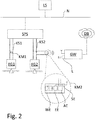
- FIG. 1 an embodiment of the system according to the invention for the transmission of diagnostic data from a large number of field devices in a process automation system.
- Fig. 1 shows an embodiment of the system according to the invention for the transmission of diagnostic data from a large number of field devices FG1, FG2 in a process automation system.
- these field devices FG1, FG2 are flow measuring devices.
- it can be any field devices, as mentioned by way of example in the introductory part of the description, as well as any number of these field devices FG1, FG2.
- the field devices FG1, FG2 are each connected to a superordinate unit PLC by means of a communication loop KS1, KS2.
- This superordinate unit PLC is in particular a PLC or a PLC.
- the communication loops KS1, KS2 are each a 4-20 mA current loop, by means of which the respective measured process values of the field devices FG1, FG2 are transmitted to the higher-level unit PLC.
- the superordinate unit PLC itself is connected to the control center LS of the system via a network N, for example Ethernet or Profibus DP.
- a communication module KM1, KM2 is attached to the cables of the respective communication loop KS1, KS2 plugged.
- the communication modules KS1, KS2 are preferably plugged into the control cabinet on the cables of the communication loops KS1, KS2, in particular at the point where the cables of the communication loops KS1, KS2 are brought together to the higher-level unit PLC.
- the communication modules KM1, KM2 are attached to the cables of the communication loops KS1, KS2 by means of insulation displacement terminals in such a way that the communication modules KM1, KM2 are connected in parallel to the respective corresponding field device FG1, FG2, which has the advantage that the communication loops KS1, KS2 are not separated Need to become.
- the communication modules KM1, KM2 include a converter unit WE, consisting of a rectifier circuit, for generating electrical energy.
- the higher-level unit PLC is designed to generate these communication pulses.
- the communication pulses are an alternating current or an alternating voltage which is modulated onto the direct current of the communication loops KS1, KS2.
- This alternating current component is tapped off by the converter unit WE of the communication modules KM1, KM2.
- the modulated alternating current component is rectified by the rectifier circuit in the converter unit WE, passed on to an energy storage unit EE connected downstream of the traveling unit WE and stored in the energy storage unit EE.
- the communication pulse is a HART command.
- the higher-level unit PLC is then designed in such a way that it sends out the HART command at regular time intervals.
- the HART command itself is irrelevant for the field device FG1, FG2 and contains, for example, a command that is invalid for the field device FG1, FG2 or a different receive address than the network address of the field device FG1, FG2.
- the amount of electrical energy stored in the energy storage unit EE is detected.
- a query unit AE located in the communication module KM1, KM2 sends a communication command to the corresponding field device FG1, FG2 to query current diagnostic data of the field device FG1, FG2.
- the communication command which is sent from the communication module KM1, KM2 to the field device FG1, FG2 is based on HART.
- the communication command is modulated to the current value of the 4-20 mA current loop.
- the field device In contrast to the higher-level PLC unit, the field device must be HART-compatible in order to "understand" the communication command.
- the field device FG1, FG2 itself sends the desired diagnostic data by means of a HART communication pulse back to the communication module KM1, KM2.
- the communication module KM1, KM2 Before commissioning, however, the communication module KM1, KM2 must be configured in such a way that it knows the network address of the field device for querying the diagnostic data.
- the communication module KM1, KM2 After the communication module KM1, KM2 has received the diagnostic data from the field device FG1, FG2, it enriches them with additional information, such as a time stamp and the identification of the field device FG1, FG2.
- the diagnostic data are then transmitted wirelessly to a receiving unit GW using electrical energy from the energy storage unit EE by means of a transmitting unit SE, whereupon the receiving unit GW stores the diagnostic information.
- the interrogation or transmission of the interrogated diagnostic data is triggered by a command, for example by pressing a button on the housing of the respective communication module KM1, KM2.
- the stored diagnostic information can then be read out from the receiving unit GW by means of a PC, a mobile operating unit or a mobile terminal device by means of a wired or wireless communication connection.
- the receiving unit GW is connected to the control center LS of the system and makes the stored diagnostic information available to the control center.
Landscapes
- Physics & Mathematics (AREA)
- General Physics & Mathematics (AREA)
- Engineering & Computer Science (AREA)
- Automation & Control Theory (AREA)
- Arrangements For Transmission Of Measured Signals (AREA)
- Testing And Monitoring For Control Systems (AREA)
Claims (13)
- Procédé destiné à la transmission des données de diagnostic d'un appareil de terrain (FG1, FG2) dans une installation d'automatisation de process, l'appareil de terrain (FG1, FG2) étant en communication avec une unité de niveau supérieur (SPS) via une boucle de communication (KS1, KS2), la boucle de communication (KS1, KS2) présentant un courant d'alimentation / de mesure avec une composante de courant continu, et un module de communication (KM1, KM2) étant relié à la boucle de communication (KS1, KS2) de telle sorte que le module de communication (KM1, KM2) est couplé en parallèle avec l'appareil de terrain (FG1, FG2), lequel procédé comprend les étapes suivantes :- Génération d'impulsions de communication au moyen de l'unité de niveau supérieur (SPS), lesquelles impulsions de communication sont modulées en tant que courant alternatif ou en tant que tension alternative sur la composante de courant continu de la boucle de communication (KS1, KS2), les impulsions de communication étant des commandes HART, lesquelles commandes contiennent une commande non valide pour l'appareil de terrain (FG1, FG2) ou une adresse de réception différente de l'adresse de réseau de l'appareil de terrain (FG1, FG2) ;- Accumulation continue d'énergie électrique dans une unité d'accumulation d'énergie (EE) du module de communication au moyen d'une unité de conversion (WE) couplée en amont de l'unité d'accumulation d'énergie (EE) jusqu'à une valeur limite prédéfinie, l'unité de conversion (WE) convertissant les impulsions de communication en énergie électrique ;- Interrogation des données de diagnostic de l'appareil de terrain (FG1, FG2) par une commande de communication au moyen d'une unité d'interrogation (AE) du module de communication (KM1, KM2) ;- Réception des données de diagnostic de l'appareil de terrain (FG1, FG2) au moyen d'une commande de communication envoyée par l'appareil de terrain au moyen du module de communication (KM 1, KM2) et transmission sans fil des données de diagnostic interrogées à une unité de réception (GW) au moyen d'une unité d'émission (SE) du module de communication (KM1, KM2) dès que l'énergie électrique accumulée dans l'unité d'accumulation d'énergie (EE) atteint ou dépasse la valeur limite prédéfinie et/ou lorsque le module de communication (KM1, KM2) reçoit une commande d'interrogation ou de transmission.
- Procédé selon la revendication 1, pour lequel l'unité de réception (GW) met les données de diagnostic transmises à la disposition du système numérique de contrôle commande (LS) de l'installation.
- Procédé selon au moins l'une des revendications précédentes, pour lequel l'unité de réception (GW) fournit les données de diagnostic avec des informations supplémentaires, notamment avec l'identification de l'appareil de terrain (FG1, FG2) et/ou avec un horodatage.
- Procédé selon au moins l'une des revendications précédentes, pour lequel l'étape de transmission sans fil des données de diagnostic interrogées à l'unité de réception (GW) est réalisée après chaque interrogation des données de diagnostic par le module de communication (KM1, KM2).
- Procédé selon au moins l'une des revendications 1 à 3, pour lequel les données de diagnostic interrogées sont collectées dans le module de communication (KM1, KM2) et les données de diagnostic collectées sont transmises sans fil à l'unité de réception (GW) à intervalles de temps fixes.
- Module de communication (KM1, KM2), lequel est conçu pour être utilisé dans un procédé selon au moins l'une des revendications 1 à 5, et comprenant :- une unité d'accumulation d'énergie (EE) avec une unité de conversion en amont (WE), dans laquelle l'unité de conversion (EE) est configurée pour convertir les commandes HART contenant une commande non valide pour un appareil de terrain (FG1, FG2) pouvant être connecté au module de communication ou une adresse de réception différente de l'adresse de réseau de l'appareil de terrain pouvant être connecté (FG1, FG2) en énergie électrique, et dans laquelle l'unité d'accumulation d'énergie (EE) est configurée pour accumuler l'énergie électrique convertie ;- une unité d'interrogation (AE) pour interroger les données de diagnostic de l'appareil de terrain connectable (FG1, FG2) ; et- une unité de transmission (SE) pour transmettre sans fil les données de diagnostic interrogées à l'unité de communication (GW).
- Module de communication (KM1, KM2) selon la revendication 6, le module de communication (KM1, KM2) comprenant des bornes ou des bornes guillotines au moyen desquelles le module de communication (KM1, KM2) peut être relié aux câbles de la boucle de communication (KS1, KS2), la boucle de communication (KS1, KS2) n'étant pas interrompue lorsque le module de communication (KM1, KM2) est relié à la boucle de communication (KS1, KS2).
- Module de communication (KM 1, KM2) selon au moins l'une des revendications 6 ou 7, pour lequel l'unité d'accumulation d'énergie (EE) est formée par un condensateur, notamment par un condensateur double couche ou par un supercondensateur, ou par un accumulateur.
- Module de communication (KM1, KM2) selon au moins l'une des revendications 6 à 8, pour lequel l'unité de conversion (WE) est formée par au moins un circuit redresseur, notamment par un redresseur à diodes, à demi-onde ou à pleine onde, qui peut être relié à la boucle de communication (KS1, KS2).
- Module de communication (KM1, KM2) selon au moins l'une des revendications 6 à 9, pour lequel l'unité d'émission (SE) est située dans le boîtier du module de communication (KM1, KM2).
- Module de communication (KM1, KM2) selon au moins l'une des revendications 6 à 9, pour lequel l'unité d'émission (SE) présente un boîtier séparé et est conçue pour être reliée au module de communication (KM1, KM2), notamment via une interface.
- Système destiné à la transmission des données de diagnostic provenant d'une pluralité d'appareils de terrain (FG1, FG2), lequel système comprend :- une unité de niveau supérieur (SPS), qui communique avec les différents appareils de terrain (FG1, FG2) par l'intermédiaire d'une boucle de communication (KS1, KS2) séparée, les boucles de communication (KS1, KS2) présentant chacune un courant d'alimentation / de mesure avec une composante de courant continu, et l'unité de niveau supérieur (SPS) étant conçue pour générer des impulsions de communication, lesquelles impulsions de communication sont modulées en tant que courant alternatif ou en tant que tension alternative sur la composante de courant continu des boucles de communication (KS1, KS2), lesdites impulsions de communication étant des commandes HART contenant une commande non valide pour l'appareil de terrain respectif (FG1, FG2) ou une adresse de réception différente de l'adresse de réseau de l'appareil de terrain respectif (FG1, FG2) ;- une pluralité de modules de communication (KM1, KM2), lesquels modules sont respectivement reliés aux différentes boucles de communication (KS1, KS2) de telle sorte que les modules de communication (KM1, KM2) sont respectivement reliés en parallèle à l'appareil de terrain respectif (FG1, FG2), et lesquels modules comprennent chacun au moins une unité d'accumulation d'énergie (EE), une unité d'interrogation (AE) et une unité d'émission (SE), l'unité d'accumulation d'énergie (EE) étant conçue pour accumuler l'énergie électrique en ce qu'une unité de conversion (WE) connectée en amont de l'unité d'accumulation d'énergie (EE) est conçue pour convertir les impulsions de communication en énergie électrique ;- une unité de réception (GW), chacun des modules de communication (KM1, KM2) étant conçu pour interroger les données de diagnostic à partir des appareils de terrain respectifs (FG1, FG2) par le biais de l'unité d'interrogation (AE), et pour transmettre les données de diagnostic interrogées via une liaison radio sans fil à l'unité de réception (GW) au moyen de l'unité d'émission (SE), dès qu'une valeur limite prédéterminée d'énergie accumulée est atteinte dans l'unité d'accumulation d'énergie (EE) du module de communication (KM1, KM2) ou lorsque le module de communication (KM1, KM2) reçoit une commande d'interrogation ou de transmission.
- Système selon la revendication 12, pour lequel l'unité de réception (EE) est conçue pour être en communication avec le système numérique de contrôle commande (LS) de l'installation par l'intermédiaire d'un réseau sans fil ou filaire, et pour mettre les données de diagnostic transmises à la disposition du système de commande via le réseau.
Applications Claiming Priority (2)
| Application Number | Priority Date | Filing Date | Title |
|---|---|---|---|
| DE102016120108.1A DE102016120108A1 (de) | 2016-10-21 | 2016-10-21 | Verfahren, Kommunikationsmodul und System zur Übermittlung von Diagnosedaten eines Feldgeräts in einer Anlage der Prozessautomatisierung |
| PCT/EP2017/073229 WO2018072939A1 (fr) | 2016-10-21 | 2017-09-15 | Procédé, module de communication et système de transmission de données de diagnostic d'un appareil de terrain dans une installation d'automatisation de processus |
Publications (2)
| Publication Number | Publication Date |
|---|---|
| EP3529672A1 EP3529672A1 (fr) | 2019-08-28 |
| EP3529672B1 true EP3529672B1 (fr) | 2021-11-03 |
Family
ID=60009587
Family Applications (1)
| Application Number | Title | Priority Date | Filing Date |
|---|---|---|---|
| EP17778203.4A Active EP3529672B1 (fr) | 2016-10-21 | 2017-09-15 | Procédé, module de communication et système de transmission de données de diagnostic d'un appareil de terrain dans une installation d'automatisation de processus |
Country Status (4)
| Country | Link |
|---|---|
| US (1) | US11281177B2 (fr) |
| EP (1) | EP3529672B1 (fr) |
| DE (1) | DE102016120108A1 (fr) |
| WO (1) | WO2018072939A1 (fr) |
Families Citing this family (3)
| Publication number | Priority date | Publication date | Assignee | Title |
|---|---|---|---|---|
| DE102017118585A1 (de) * | 2017-08-15 | 2019-02-21 | Endress+Hauser Process Solutions Ag | Drahtlosadapter und System |
| DE102018124902A1 (de) * | 2018-10-09 | 2020-04-09 | Endress+Hauser SE+Co. KG | Feldgeräteadapter zur drahtlosen Datenübertragung |
| DE102020101346A1 (de) | 2020-01-21 | 2021-07-22 | Deutsche Bahn Ag | Überwachungseinheit, fahrscheinentwerter und anordnung |
Family Cites Families (27)
| Publication number | Priority date | Publication date | Assignee | Title |
|---|---|---|---|---|
| US6251078B1 (en) * | 1999-04-12 | 2001-06-26 | Scimed Life Systems, Inc. | Preamplifier and protection circuit for an ultrasound catheter |
| DE10153151A1 (de) * | 2001-10-27 | 2003-05-15 | Airbus Gmbh | Diagnosesystem sowie Diagnoseverfahren zur Unterstützung der Flugzeugwartung |
| US20030233165A1 (en) * | 2002-06-13 | 2003-12-18 | Mark Hein | Computer controlled order filling system using wireless communications |
| US6783425B2 (en) * | 2002-08-26 | 2004-08-31 | Shoot The Moon Products Ii, Llc | Single wire automatically navigated vehicle systems and methods for toy applications |
| US20050211187A1 (en) * | 2004-03-12 | 2005-09-29 | Harman Larry L | Control station with integrated collar recharging docking station for pet electronics products |
| US7262693B2 (en) * | 2004-06-28 | 2007-08-28 | Rosemount Inc. | Process field device with radio frequency communication |
| CA2615357A1 (fr) * | 2005-07-15 | 2007-01-25 | Southwest Windpower, Inc. | Turbine et procede de fabrication |
| TWM287153U (en) * | 2005-08-17 | 2006-02-11 | Jiun-Guang Luo | Solar energy anion device |
| US20070159842A1 (en) * | 2006-01-11 | 2007-07-12 | Fiber Glow Llc | Fiber optic LED decoration lights |
| US7663350B2 (en) * | 2006-07-13 | 2010-02-16 | Endress + Hauser Flowtec Ag | External electrical energy supply for field device |
| US20080307143A1 (en) * | 2007-06-11 | 2008-12-11 | Sunix Co., Ltd. | Modularized (block) channel technology with expansion of different to output interfaces |
| TW200939886A (en) * | 2008-02-05 | 2009-09-16 | Microsemi Corp | Balancing arrangement with reduced amount of balancing transformers |
| WO2009131675A1 (fr) * | 2008-04-22 | 2009-10-29 | Afl Telecommunications, Llc | Interface de démarcation xdsl universelle avec capacité multifonctionnelle et amélioration d’efficacité de signal |
| JP2013501665A (ja) * | 2009-08-07 | 2013-01-17 | オークランド ユニサービシズ リミテッド | 道路から電気エネルギーを得る電気車両システム |
| US9197143B1 (en) | 2010-03-02 | 2015-11-24 | Lord Corporation | Harvesting power from multiple energy sources |
| US10761524B2 (en) | 2010-08-12 | 2020-09-01 | Rosemount Inc. | Wireless adapter with process diagnostics |
| AT13441U1 (de) * | 2011-12-23 | 2013-12-15 | Tridonic Gmbh & Co Kg | Betriebsgerät mit leistungsfaktorkorrektur |
| US20140143607A1 (en) * | 2012-02-10 | 2014-05-22 | Phoenix Contact Development & Manufacturing, Inc. | Dedicated Network Diagnostics Module for a Process Network |
| US20130340977A1 (en) * | 2012-06-21 | 2013-12-26 | Gregory L. Singleton | Heat sink for use in an electronics system |
| GB2509174A (en) * | 2012-12-24 | 2014-06-25 | Cambium Networks Ltd | Passive circuit for signaling synchronization information over an Ethernet cable, with inductive coupling through a common magnetic core |
| WO2014178650A1 (fr) * | 2013-04-30 | 2014-11-06 | 한국철도기술연구원 | Dispositif de collecte d'énergie et dispositif de capteur sans fil le comprenant |
| DE102013106098A1 (de) * | 2013-06-12 | 2014-12-18 | Endress + Hauser Gmbh + Co. Kg | Verfahren zur Parametrierung eines Feldgerätes |
| US9523775B2 (en) * | 2014-02-26 | 2016-12-20 | Senaya, Inc. | System to extend battery power in remote tracking devices |
| US9807459B2 (en) * | 2015-05-14 | 2017-10-31 | At&T Intellectual Property I, L.P. | Media interface device |
| TWI538342B (zh) * | 2015-06-23 | 2016-06-11 | 大鵬科技股份有限公司 | 無水線之無線電源開關控制系統 |
| US10027187B2 (en) * | 2015-07-23 | 2018-07-17 | Uncharted Power, Inc. | Wireless mesh energy network |
| DE102015117011A1 (de) * | 2015-10-06 | 2017-04-06 | Vega Grieshaber Kg | Energieversorgungseinheit für ein Funkmodul |
-
2016
- 2016-10-21 DE DE102016120108.1A patent/DE102016120108A1/de not_active Withdrawn
-
2017
- 2017-09-15 WO PCT/EP2017/073229 patent/WO2018072939A1/fr unknown
- 2017-09-15 EP EP17778203.4A patent/EP3529672B1/fr active Active
- 2017-09-15 US US16/343,089 patent/US11281177B2/en active Active
Non-Patent Citations (1)
| Title |
|---|
| None * |
Also Published As
| Publication number | Publication date |
|---|---|
| US11281177B2 (en) | 2022-03-22 |
| EP3529672A1 (fr) | 2019-08-28 |
| WO2018072939A1 (fr) | 2018-04-26 |
| US20200050165A1 (en) | 2020-02-13 |
| DE102016120108A1 (de) | 2018-04-26 |
Similar Documents
| Publication | Publication Date | Title |
|---|---|---|
| EP2984530B1 (fr) | Appareil d'alimentation d'un transducteur de mesure, système destiné à être utilisé dans les techniques d'automatisation, et procédé d'utilisation dudit système | |
| EP3529672B1 (fr) | Procédé, module de communication et système de transmission de données de diagnostic d'un appareil de terrain dans une installation d'automatisation de processus | |
| DE102014105075B4 (de) | Verfahren und Kommunikationsanordnung zur Datenkommunikation | |
| DE102013111714A1 (de) | Verfahren zur Funktionseinstellung einer Messstelle und Messstelle | |
| DE102013013299A1 (de) | Verfahren zum Bedienen eines Feldgeräts | |
| DE10159697A1 (de) | Redundante Einrichtungen in einem Prozesssteuersystem | |
| DE102008036967A1 (de) | Universelle Schnittstelle für einen Wireless Adapter | |
| DE102017105809A1 (de) | Messanordnung | |
| DE102015117010A1 (de) | Modular aufgebautes Feldgerät | |
| WO2017041987A1 (fr) | Circuit électronique pour l'alimentation autonome d'un premier et d'un second module d'un appareil de terrain, appareil de terrain et procédé correspondant | |
| WO2017182201A1 (fr) | Procédé de surveillance de l'état d'une installation pour l'automatisation de processus | |
| EP3283928B1 (fr) | Procédé de branchement ou de débranchement automatique d'une résistance de communication d'un dispositif hart | |
| EP3355139B1 (fr) | Procédé de fonctionnement d'un système d'automatisation, système d'automatisation, appareil de terrain et contrôleur destinés à exécuter ledit procédé | |
| WO2019007668A1 (fr) | Adaptateur d'appareil de terrain pour la transmission sans fil de données | |
| EP3348021A1 (fr) | Procédé pour garantir le fonctionnement d'un module sans fil d'un appareil de terrain | |
| EP3465364A1 (fr) | Adaptateur radio pour un appareil de terrain pourvu d'une antenne pour deux normes de communication | |
| EP3894970B1 (fr) | Adaptateur d'appareil de terrain pour la transmission sans fil de données | |
| DE102013103212A1 (de) | System zur Bestimmung und/oder Überwachung und/oder Beeinflussung zumindest einer Prozessgröße | |
| DE102004052488A1 (de) | Verfahren zum Bedienen eines Feldgerätes der Automatisierungstechnik | |
| DE102011086054B4 (de) | System zur Sicherstellung der Verfügbarkeit eines Bussystems der Automatisierungstechnik | |
| DE102018118872A1 (de) | Verfahren zur Überprüfung der Datenübertragung eines elektronischen Schaltgerätes | |
| DE102017128903A1 (de) | Netzwerk der Automatisierungstechnik | |
| WO2020011480A1 (fr) | Module de borne, module de tête et système permettant de collecter des données présentes dans une installation utilisant des techniques d'automatisation | |
| WO2019034336A1 (fr) | Adaptateur sans fil et systeme de fil | |
| WO2021239350A1 (fr) | Appareil de terrain pour vérifier la qualité d'une connexion réseau |
Legal Events
| Date | Code | Title | Description |
|---|---|---|---|
| STAA | Information on the status of an ep patent application or granted ep patent |
Free format text: STATUS: UNKNOWN |
|
| STAA | Information on the status of an ep patent application or granted ep patent |
Free format text: STATUS: THE INTERNATIONAL PUBLICATION HAS BEEN MADE |
|
| PUAI | Public reference made under article 153(3) epc to a published international application that has entered the european phase |
Free format text: ORIGINAL CODE: 0009012 |
|
| STAA | Information on the status of an ep patent application or granted ep patent |
Free format text: STATUS: REQUEST FOR EXAMINATION WAS MADE |
|
| 17P | Request for examination filed |
Effective date: 20190326 |
|
| AK | Designated contracting states |
Kind code of ref document: A1 Designated state(s): AL AT BE BG CH CY CZ DE DK EE ES FI FR GB GR HR HU IE IS IT LI LT LU LV MC MK MT NL NO PL PT RO RS SE SI SK SM TR |
|
| AX | Request for extension of the european patent |
Extension state: BA ME |
|
| DAV | Request for validation of the european patent (deleted) | ||
| DAX | Request for extension of the european patent (deleted) | ||
| STAA | Information on the status of an ep patent application or granted ep patent |
Free format text: STATUS: EXAMINATION IS IN PROGRESS |
|
| 17Q | First examination report despatched |
Effective date: 20200224 |
|
| STAA | Information on the status of an ep patent application or granted ep patent |
Free format text: STATUS: EXAMINATION IS IN PROGRESS |
|
| GRAP | Despatch of communication of intention to grant a patent |
Free format text: ORIGINAL CODE: EPIDOSNIGR1 |
|
| STAA | Information on the status of an ep patent application or granted ep patent |
Free format text: STATUS: GRANT OF PATENT IS INTENDED |
|
| INTG | Intention to grant announced |
Effective date: 20210624 |
|
| GRAS | Grant fee paid |
Free format text: ORIGINAL CODE: EPIDOSNIGR3 |
|
| GRAA | (expected) grant |
Free format text: ORIGINAL CODE: 0009210 |
|
| STAA | Information on the status of an ep patent application or granted ep patent |
Free format text: STATUS: THE PATENT HAS BEEN GRANTED |
|
| AK | Designated contracting states |
Kind code of ref document: B1 Designated state(s): AL AT BE BG CH CY CZ DE DK EE ES FI FR GB GR HR HU IE IS IT LI LT LU LV MC MK MT NL NO PL PT RO RS SE SI SK SM TR |
|
| REG | Reference to a national code |
Ref country code: GB Ref legal event code: FG4D Free format text: NOT ENGLISH |
|
| REG | Reference to a national code |
Ref country code: AT Ref legal event code: REF Ref document number: 1444524 Country of ref document: AT Kind code of ref document: T Effective date: 20211115 Ref country code: CH Ref legal event code: EP |
|
| REG | Reference to a national code |
Ref country code: DE Ref legal event code: R096 Ref document number: 502017011934 Country of ref document: DE |
|
| REG | Reference to a national code |
Ref country code: IE Ref legal event code: FG4D Free format text: LANGUAGE OF EP DOCUMENT: GERMAN |
|
| REG | Reference to a national code |
Ref country code: NL Ref legal event code: FP |
|
| REG | Reference to a national code |
Ref country code: LT Ref legal event code: MG9D |
|
| PG25 | Lapsed in a contracting state [announced via postgrant information from national office to epo] |
Ref country code: RS Free format text: LAPSE BECAUSE OF FAILURE TO SUBMIT A TRANSLATION OF THE DESCRIPTION OR TO PAY THE FEE WITHIN THE PRESCRIBED TIME-LIMIT Effective date: 20211103 Ref country code: LT Free format text: LAPSE BECAUSE OF FAILURE TO SUBMIT A TRANSLATION OF THE DESCRIPTION OR TO PAY THE FEE WITHIN THE PRESCRIBED TIME-LIMIT Effective date: 20211103 Ref country code: FI Free format text: LAPSE BECAUSE OF FAILURE TO SUBMIT A TRANSLATION OF THE DESCRIPTION OR TO PAY THE FEE WITHIN THE PRESCRIBED TIME-LIMIT Effective date: 20211103 Ref country code: BG Free format text: LAPSE BECAUSE OF FAILURE TO SUBMIT A TRANSLATION OF THE DESCRIPTION OR TO PAY THE FEE WITHIN THE PRESCRIBED TIME-LIMIT Effective date: 20220203 |
|
| PG25 | Lapsed in a contracting state [announced via postgrant information from national office to epo] |
Ref country code: IS Free format text: LAPSE BECAUSE OF FAILURE TO SUBMIT A TRANSLATION OF THE DESCRIPTION OR TO PAY THE FEE WITHIN THE PRESCRIBED TIME-LIMIT Effective date: 20220303 Ref country code: SE Free format text: LAPSE BECAUSE OF FAILURE TO SUBMIT A TRANSLATION OF THE DESCRIPTION OR TO PAY THE FEE WITHIN THE PRESCRIBED TIME-LIMIT Effective date: 20211103 Ref country code: PT Free format text: LAPSE BECAUSE OF FAILURE TO SUBMIT A TRANSLATION OF THE DESCRIPTION OR TO PAY THE FEE WITHIN THE PRESCRIBED TIME-LIMIT Effective date: 20220303 Ref country code: PL Free format text: LAPSE BECAUSE OF FAILURE TO SUBMIT A TRANSLATION OF THE DESCRIPTION OR TO PAY THE FEE WITHIN THE PRESCRIBED TIME-LIMIT Effective date: 20211103 Ref country code: NO Free format text: LAPSE BECAUSE OF FAILURE TO SUBMIT A TRANSLATION OF THE DESCRIPTION OR TO PAY THE FEE WITHIN THE PRESCRIBED TIME-LIMIT Effective date: 20220203 Ref country code: LV Free format text: LAPSE BECAUSE OF FAILURE TO SUBMIT A TRANSLATION OF THE DESCRIPTION OR TO PAY THE FEE WITHIN THE PRESCRIBED TIME-LIMIT Effective date: 20211103 Ref country code: HR Free format text: LAPSE BECAUSE OF FAILURE TO SUBMIT A TRANSLATION OF THE DESCRIPTION OR TO PAY THE FEE WITHIN THE PRESCRIBED TIME-LIMIT Effective date: 20211103 Ref country code: GR Free format text: LAPSE BECAUSE OF FAILURE TO SUBMIT A TRANSLATION OF THE DESCRIPTION OR TO PAY THE FEE WITHIN THE PRESCRIBED TIME-LIMIT Effective date: 20220204 Ref country code: ES Free format text: LAPSE BECAUSE OF FAILURE TO SUBMIT A TRANSLATION OF THE DESCRIPTION OR TO PAY THE FEE WITHIN THE PRESCRIBED TIME-LIMIT Effective date: 20211103 |
|
| PG25 | Lapsed in a contracting state [announced via postgrant information from national office to epo] |
Ref country code: SM Free format text: LAPSE BECAUSE OF FAILURE TO SUBMIT A TRANSLATION OF THE DESCRIPTION OR TO PAY THE FEE WITHIN THE PRESCRIBED TIME-LIMIT Effective date: 20211103 Ref country code: SK Free format text: LAPSE BECAUSE OF FAILURE TO SUBMIT A TRANSLATION OF THE DESCRIPTION OR TO PAY THE FEE WITHIN THE PRESCRIBED TIME-LIMIT Effective date: 20211103 Ref country code: RO Free format text: LAPSE BECAUSE OF FAILURE TO SUBMIT A TRANSLATION OF THE DESCRIPTION OR TO PAY THE FEE WITHIN THE PRESCRIBED TIME-LIMIT Effective date: 20211103 Ref country code: EE Free format text: LAPSE BECAUSE OF FAILURE TO SUBMIT A TRANSLATION OF THE DESCRIPTION OR TO PAY THE FEE WITHIN THE PRESCRIBED TIME-LIMIT Effective date: 20211103 Ref country code: DK Free format text: LAPSE BECAUSE OF FAILURE TO SUBMIT A TRANSLATION OF THE DESCRIPTION OR TO PAY THE FEE WITHIN THE PRESCRIBED TIME-LIMIT Effective date: 20211103 Ref country code: CZ Free format text: LAPSE BECAUSE OF FAILURE TO SUBMIT A TRANSLATION OF THE DESCRIPTION OR TO PAY THE FEE WITHIN THE PRESCRIBED TIME-LIMIT Effective date: 20211103 |
|
| REG | Reference to a national code |
Ref country code: DE Ref legal event code: R097 Ref document number: 502017011934 Country of ref document: DE |
|
| PLBE | No opposition filed within time limit |
Free format text: ORIGINAL CODE: 0009261 |
|
| STAA | Information on the status of an ep patent application or granted ep patent |
Free format text: STATUS: NO OPPOSITION FILED WITHIN TIME LIMIT |
|
| 26N | No opposition filed |
Effective date: 20220804 |
|
| PG25 | Lapsed in a contracting state [announced via postgrant information from national office to epo] |
Ref country code: AL Free format text: LAPSE BECAUSE OF FAILURE TO SUBMIT A TRANSLATION OF THE DESCRIPTION OR TO PAY THE FEE WITHIN THE PRESCRIBED TIME-LIMIT Effective date: 20211103 |
|
| PG25 | Lapsed in a contracting state [announced via postgrant information from national office to epo] |
Ref country code: SI Free format text: LAPSE BECAUSE OF FAILURE TO SUBMIT A TRANSLATION OF THE DESCRIPTION OR TO PAY THE FEE WITHIN THE PRESCRIBED TIME-LIMIT Effective date: 20211103 |
|
| PG25 | Lapsed in a contracting state [announced via postgrant information from national office to epo] |
Ref country code: MC Free format text: LAPSE BECAUSE OF FAILURE TO SUBMIT A TRANSLATION OF THE DESCRIPTION OR TO PAY THE FEE WITHIN THE PRESCRIBED TIME-LIMIT Effective date: 20211103 |
|
| REG | Reference to a national code |
Ref country code: CH Ref legal event code: PL |
|
| REG | Reference to a national code |
Ref country code: BE Ref legal event code: MM Effective date: 20220930 |
|
| PG25 | Lapsed in a contracting state [announced via postgrant information from national office to epo] |
Ref country code: LU Free format text: LAPSE BECAUSE OF NON-PAYMENT OF DUE FEES Effective date: 20220915 |
|
| P01 | Opt-out of the competence of the unified patent court (upc) registered |
Effective date: 20230601 |
|
| PG25 | Lapsed in a contracting state [announced via postgrant information from national office to epo] |
Ref country code: LI Free format text: LAPSE BECAUSE OF NON-PAYMENT OF DUE FEES Effective date: 20220930 Ref country code: IE Free format text: LAPSE BECAUSE OF NON-PAYMENT OF DUE FEES Effective date: 20220915 Ref country code: CH Free format text: LAPSE BECAUSE OF NON-PAYMENT OF DUE FEES Effective date: 20220930 |
|
| PG25 | Lapsed in a contracting state [announced via postgrant information from national office to epo] |
Ref country code: BE Free format text: LAPSE BECAUSE OF NON-PAYMENT OF DUE FEES Effective date: 20220930 |
|
| PGFP | Annual fee paid to national office [announced via postgrant information from national office to epo] |
Ref country code: NL Payment date: 20230920 Year of fee payment: 7 Ref country code: GB Payment date: 20230920 Year of fee payment: 7 |
|
| REG | Reference to a national code |
Ref country code: AT Ref legal event code: MM01 Ref document number: 1444524 Country of ref document: AT Kind code of ref document: T Effective date: 20220915 |
|
| PGFP | Annual fee paid to national office [announced via postgrant information from national office to epo] |
Ref country code: FR Payment date: 20230928 Year of fee payment: 7 Ref country code: DE Payment date: 20230920 Year of fee payment: 7 |
|
| PG25 | Lapsed in a contracting state [announced via postgrant information from national office to epo] |
Ref country code: AT Free format text: LAPSE BECAUSE OF NON-PAYMENT OF DUE FEES Effective date: 20220915 |
|
| PGFP | Annual fee paid to national office [announced via postgrant information from national office to epo] |
Ref country code: IT Payment date: 20230927 Year of fee payment: 7 |
|
| PG25 | Lapsed in a contracting state [announced via postgrant information from national office to epo] |
Ref country code: HU Free format text: LAPSE BECAUSE OF FAILURE TO SUBMIT A TRANSLATION OF THE DESCRIPTION OR TO PAY THE FEE WITHIN THE PRESCRIBED TIME-LIMIT; INVALID AB INITIO Effective date: 20170915 |
|
| PG25 | Lapsed in a contracting state [announced via postgrant information from national office to epo] |
Ref country code: CY Free format text: LAPSE BECAUSE OF FAILURE TO SUBMIT A TRANSLATION OF THE DESCRIPTION OR TO PAY THE FEE WITHIN THE PRESCRIBED TIME-LIMIT Effective date: 20211103 |