EP3529529B1 - Display support system - Google Patents
Display support system Download PDFInfo
- Publication number
- EP3529529B1 EP3529529B1 EP17791445.4A EP17791445A EP3529529B1 EP 3529529 B1 EP3529529 B1 EP 3529529B1 EP 17791445 A EP17791445 A EP 17791445A EP 3529529 B1 EP3529529 B1 EP 3529529B1
- Authority
- EP
- European Patent Office
- Prior art keywords
- arm
- support system
- biasing member
- pulley
- axis
- Prior art date
- Legal status (The legal status is an assumption and is not a legal conclusion. Google has not performed a legal analysis and makes no representation as to the accuracy of the status listed.)
- Active
Links
- 238000000034 method Methods 0.000 claims description 4
- 239000012815 thermoplastic material Substances 0.000 claims description 3
- 230000009977 dual effect Effects 0.000 description 4
- 239000004973 liquid crystal related substance Substances 0.000 description 3
- 229920001971 elastomer Polymers 0.000 description 2
- 239000000806 elastomer Substances 0.000 description 2
- 238000004040 coloring Methods 0.000 description 1
- 239000013013 elastic material Substances 0.000 description 1
- 238000004519 manufacturing process Methods 0.000 description 1
- 239000000463 material Substances 0.000 description 1
- 238000012986 modification Methods 0.000 description 1
- 230000004048 modification Effects 0.000 description 1
- 238000000465 moulding Methods 0.000 description 1
- 230000000087 stabilizing effect Effects 0.000 description 1
- 229920006344 thermoplastic copolyester Polymers 0.000 description 1
- 230000000007 visual effect Effects 0.000 description 1
Images


Classifications
-
- F—MECHANICAL ENGINEERING; LIGHTING; HEATING; WEAPONS; BLASTING
- F16—ENGINEERING ELEMENTS AND UNITS; GENERAL MEASURES FOR PRODUCING AND MAINTAINING EFFECTIVE FUNCTIONING OF MACHINES OR INSTALLATIONS; THERMAL INSULATION IN GENERAL
- F16M—FRAMES, CASINGS OR BEDS OF ENGINES, MACHINES OR APPARATUS, NOT SPECIFIC TO ENGINES, MACHINES OR APPARATUS PROVIDED FOR ELSEWHERE; STANDS; SUPPORTS
- F16M13/00—Other supports for positioning apparatus or articles; Means for steadying hand-held apparatus or articles
- F16M13/02—Other supports for positioning apparatus or articles; Means for steadying hand-held apparatus or articles for supporting on, or attaching to, an object, e.g. tree, gate, window-frame, cycle
- F16M13/022—Other supports for positioning apparatus or articles; Means for steadying hand-held apparatus or articles for supporting on, or attaching to, an object, e.g. tree, gate, window-frame, cycle repositionable
-
- F—MECHANICAL ENGINEERING; LIGHTING; HEATING; WEAPONS; BLASTING
- F16—ENGINEERING ELEMENTS AND UNITS; GENERAL MEASURES FOR PRODUCING AND MAINTAINING EFFECTIVE FUNCTIONING OF MACHINES OR INSTALLATIONS; THERMAL INSULATION IN GENERAL
- F16M—FRAMES, CASINGS OR BEDS OF ENGINES, MACHINES OR APPARATUS, NOT SPECIFIC TO ENGINES, MACHINES OR APPARATUS PROVIDED FOR ELSEWHERE; STANDS; SUPPORTS
- F16M11/00—Stands or trestles as supports for apparatus or articles placed thereon ; Stands for scientific apparatus such as gravitational force meters
- F16M11/02—Heads
- F16M11/04—Means for attachment of apparatus; Means allowing adjustment of the apparatus relatively to the stand
- F16M11/06—Means for attachment of apparatus; Means allowing adjustment of the apparatus relatively to the stand allowing pivoting
- F16M11/12—Means for attachment of apparatus; Means allowing adjustment of the apparatus relatively to the stand allowing pivoting in more than one direction
- F16M11/14—Means for attachment of apparatus; Means allowing adjustment of the apparatus relatively to the stand allowing pivoting in more than one direction with ball-joint
-
- F—MECHANICAL ENGINEERING; LIGHTING; HEATING; WEAPONS; BLASTING
- F16—ENGINEERING ELEMENTS AND UNITS; GENERAL MEASURES FOR PRODUCING AND MAINTAINING EFFECTIVE FUNCTIONING OF MACHINES OR INSTALLATIONS; THERMAL INSULATION IN GENERAL
- F16M—FRAMES, CASINGS OR BEDS OF ENGINES, MACHINES OR APPARATUS, NOT SPECIFIC TO ENGINES, MACHINES OR APPARATUS PROVIDED FOR ELSEWHERE; STANDS; SUPPORTS
- F16M11/00—Stands or trestles as supports for apparatus or articles placed thereon ; Stands for scientific apparatus such as gravitational force meters
- F16M11/20—Undercarriages with or without wheels
- F16M11/2092—Undercarriages with or without wheels comprising means allowing depth adjustment, i.e. forward-backward translation of the head relatively to the undercarriage
-
- F—MECHANICAL ENGINEERING; LIGHTING; HEATING; WEAPONS; BLASTING
- F16—ENGINEERING ELEMENTS AND UNITS; GENERAL MEASURES FOR PRODUCING AND MAINTAINING EFFECTIVE FUNCTIONING OF MACHINES OR INSTALLATIONS; THERMAL INSULATION IN GENERAL
- F16M—FRAMES, CASINGS OR BEDS OF ENGINES, MACHINES OR APPARATUS, NOT SPECIFIC TO ENGINES, MACHINES OR APPARATUS PROVIDED FOR ELSEWHERE; STANDS; SUPPORTS
- F16M11/00—Stands or trestles as supports for apparatus or articles placed thereon ; Stands for scientific apparatus such as gravitational force meters
- F16M11/20—Undercarriages with or without wheels
- F16M11/24—Undercarriages with or without wheels changeable in height or length of legs, also for transport only, e.g. by means of tubes screwed into each other
-
- F—MECHANICAL ENGINEERING; LIGHTING; HEATING; WEAPONS; BLASTING
- F16—ENGINEERING ELEMENTS AND UNITS; GENERAL MEASURES FOR PRODUCING AND MAINTAINING EFFECTIVE FUNCTIONING OF MACHINES OR INSTALLATIONS; THERMAL INSULATION IN GENERAL
- F16M—FRAMES, CASINGS OR BEDS OF ENGINES, MACHINES OR APPARATUS, NOT SPECIFIC TO ENGINES, MACHINES OR APPARATUS PROVIDED FOR ELSEWHERE; STANDS; SUPPORTS
- F16M13/00—Other supports for positioning apparatus or articles; Means for steadying hand-held apparatus or articles
- F16M13/02—Other supports for positioning apparatus or articles; Means for steadying hand-held apparatus or articles for supporting on, or attaching to, an object, e.g. tree, gate, window-frame, cycle
-
- F—MECHANICAL ENGINEERING; LIGHTING; HEATING; WEAPONS; BLASTING
- F16—ENGINEERING ELEMENTS AND UNITS; GENERAL MEASURES FOR PRODUCING AND MAINTAINING EFFECTIVE FUNCTIONING OF MACHINES OR INSTALLATIONS; THERMAL INSULATION IN GENERAL
- F16M—FRAMES, CASINGS OR BEDS OF ENGINES, MACHINES OR APPARATUS, NOT SPECIFIC TO ENGINES, MACHINES OR APPARATUS PROVIDED FOR ELSEWHERE; STANDS; SUPPORTS
- F16M11/00—Stands or trestles as supports for apparatus or articles placed thereon ; Stands for scientific apparatus such as gravitational force meters
- F16M11/02—Heads
- F16M11/04—Means for attachment of apparatus; Means allowing adjustment of the apparatus relatively to the stand
- F16M11/06—Means for attachment of apparatus; Means allowing adjustment of the apparatus relatively to the stand allowing pivoting
-
- F—MECHANICAL ENGINEERING; LIGHTING; HEATING; WEAPONS; BLASTING
- F16—ENGINEERING ELEMENTS AND UNITS; GENERAL MEASURES FOR PRODUCING AND MAINTAINING EFFECTIVE FUNCTIONING OF MACHINES OR INSTALLATIONS; THERMAL INSULATION IN GENERAL
- F16M—FRAMES, CASINGS OR BEDS OF ENGINES, MACHINES OR APPARATUS, NOT SPECIFIC TO ENGINES, MACHINES OR APPARATUS PROVIDED FOR ELSEWHERE; STANDS; SUPPORTS
- F16M2200/00—Details of stands or supports
- F16M2200/04—Balancing means
- F16M2200/044—Balancing means for balancing rotational movement of the undercarriage
-
- F—MECHANICAL ENGINEERING; LIGHTING; HEATING; WEAPONS; BLASTING
- F16—ENGINEERING ELEMENTS AND UNITS; GENERAL MEASURES FOR PRODUCING AND MAINTAINING EFFECTIVE FUNCTIONING OF MACHINES OR INSTALLATIONS; THERMAL INSULATION IN GENERAL
- F16M—FRAMES, CASINGS OR BEDS OF ENGINES, MACHINES OR APPARATUS, NOT SPECIFIC TO ENGINES, MACHINES OR APPARATUS PROVIDED FOR ELSEWHERE; STANDS; SUPPORTS
- F16M2200/00—Details of stands or supports
- F16M2200/06—Arms
- F16M2200/063—Parallelogram arms
-
- F—MECHANICAL ENGINEERING; LIGHTING; HEATING; WEAPONS; BLASTING
- F16—ENGINEERING ELEMENTS AND UNITS; GENERAL MEASURES FOR PRODUCING AND MAINTAINING EFFECTIVE FUNCTIONING OF MACHINES OR INSTALLATIONS; THERMAL INSULATION IN GENERAL
- F16M—FRAMES, CASINGS OR BEDS OF ENGINES, MACHINES OR APPARATUS, NOT SPECIFIC TO ENGINES, MACHINES OR APPARATUS PROVIDED FOR ELSEWHERE; STANDS; SUPPORTS
- F16M2200/00—Details of stands or supports
- F16M2200/06—Arms
- F16M2200/068—Arms being part of the undercarriage
Definitions
- Various exemplary embodiments relate to a support system used to moveably support electronic displays such as monitors or TVs.
- Modern screen-based display devices are typically flat-screen monitors such as liquid crystal display (LCD) or plasma screen displays. Such devices can be mounted on elevated support devices such as a support arm which can then be secured to a surface such that the flat-screen monitor is held above or in front of the surface.
- DE 90 04 843 U1 discloses a reading aid with an adjustable bookkeeping plate.
- FR 2 922 624 A1 discloses an arm having an articulation and a tie rod associated with each other and connecting parallelograms between each other.
- US 2005/011045 A1 discloses a hinge including a bracket, two fixing seats pivotally connected to the bracket, at least one base, at least one first arm pivotally connected between the at least one base and the at least one fixing seat and at least one second arm pivotally connected between the at least one base and the at least one fixing seat.
- US 2007/102596 A1 discloses a support assembly for a liquid crystal display including a main frame, a connecting seat mounted to an end of the main frame, a coupler mounted to the connecting seat, a liquid crystal display mounting member mounted to the connecting seat, and a tension adjusting device.
- US 5 435 515 A discloses a support arm of a camera stabilizing device which is provided with a tensioning assembly which is mated to the support arm in a fashion which permits adjustment of the geometric relationship between the end points of the tensioning assembly and the remaining structures which comprise the support arm.
- a support system for a display device is provided according to claim 1.
- a support system for a display device includes a support structure having a first arm and a second arm rotatably connected to the first arm about a first axis.
- a biasing system includes a biasing member extending between the first arm and the second arm. The biasing member provides a force to balance a load applied to the support structure.
- An adjustment mechanism connected to the biasing system includes a moveable fulcrum for adjusting the force provided by the biasing member.
- the present invention further provides a method of adjusting a support system for display device according to claim 13.
- FIG. 1 shows an exemplary embodiment of a support system 20 for a display that includes a first arm 22 having a mounting portion 24 at a proximal end for rotatably connecting the support system to a surface (not shown).
- the mounting portion 24 can include a cylindrical cavity 28 for slidably receiving a mounting member that can be connected to various surfaces or supports, such as desk, tables, walls, etc. as would be understood by one of ordinary skill in the art.
- a proximal portion of a second arm 30 is rotatably connected to a distal portion of the first arm 22.
- a motion joint 32 is rotatably connected to the distal potion of the second arm 30.
- a proximal portion of a third arm 34 is rotatably connected to the motion joint 32 by a link member 36.
- a mounting head 38 is rotatably connected to a distal portion of the third arm 34 and connected to display mount 40, for example a VESA type display mount.
- Each of the first, second, and third arms 22, 30, 34 can include a one piece or two piece housing where the first and second pieces are connected to one another. Other housing pieces can be connected as needed.
- One or more clips 43 can be positioned on the one or more of the arms to organize and retain cables running to the display.
- the first arm 22, second arm 30, motion joint 32, third arm 34 and link member 36 make up an exemplary embodiment of a support structure, although other variations of support structures may also be used.
- the first arm 22 can rotate relative to the support or surface about a first vertical axis Y1.
- the second arm 30 can rotate relative to the first am 22 about a first horizontal axis X1.
- the motion joint 32 can rotate relative to the second arm 30 about a second horizontal axis X2.
- the link member 36 can rotate relative to the motion joint 32 about a second vertical axis Y2 and the third arm 34 can rotate relative to the link member 36 about a third vertical axis Y3.
- the mounting head 38 can rotate relative to the third arm 34 about a fourth vertical axis Y4 and can include a pivoting portion that rotates about a third horizontal axis X3.
- the third horizontal axis X3 is a virtual axis spaced from the pivoting portion to extend either through the display mount 40 or a portion of a display connected thereto.
- the display mount 40 can include a turntable portion 42 that is capable of rotating about an applicate axis Z1.
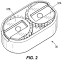
- the link member 36 can contain a gear assembly that limits rotation of the third arm 34 relative to the second arm 30.
- a gear assembly that limits rotation of the third arm 34 relative to the second arm 30.
- a first gear 37A having a first set of teeth and a second gear 37B having a second set of teeth can be rotatably connected inside of the link member 36.
- the first teeth and second teeth mesh with one another, and the end of the teeth form a stop that prevents the third arm 34 from contacting the second arm 30 during rotation.
- the gear assembly also helps to limit or prevent unwanted rotation of the third arm 24 relative to the second arm 30.
- FIGS. 3-10 show an exemplary embodiment of internal components of the support system 20 which include a biasing system 44 that provides a force to offset the torque created by the weight of a load attached to the support system, for example a monitor connected to the display mount 40.
- the biasing system 44 includes a biasing member 46 that extends from the first arm 22 to the distal portion of the second arm 30.
- the biasing member 46 extends from a first end portion 48 anchored in the first arm 22, around a first pulley 50 positioned in the first arm 22, around a second pulley 52 positioned in the second arm 30, and to a second end portion 54 anchored in the second arm 30.
- the first end portion 48 includes a loop member that is connected in the first arm 22 by a first pin 56 and the second end portion 54 includes an enlarged head that fits into a chamber 58 formed in the second arm 30.
- the first pulley 50 can include a wheel and one or more bearings connected to the first arm 22 by a second pin 60.
- the first pulley 50 is positioned below the first end portion 48 so that the biasing member 46 includes a portion extending away from the second arm 30 and a portion extending toward the second arm 30.
- a bracket 62 extends between the first end portion 48 of the biasing member 46 and the second pulley 52.
- the bracket 62 includes a first side 64 and a second side 66.
- a first set of openings 68 extends through the bottom of the first and second sides 64, 66 to receive the first pin 56 and a second set of openings 70 extends through the top of the first and second sides 64, 66 to receive a third pin 72.
- the first end portion 48 of the biasing member 46 is positioned between the first and second sides 64, 66 with the opening in the loop member aligned with the first set of openings 68.
- the second pulley 52 can include a wheel and one or more bearings, and is positioned between the first and second sides 64, 66 and rotatable about the third pin 72.
- the support system 20 can also include an adjustment mechanism 80 as best shown in FIGS. 3-6B .
- the adjustment mechanism 80 is configured to adjust the tension of the biasing member 46 to increase or decrease the amount of counter force provided by the biasing system 44.
- the adjustment mechanism 80 includes an adjustment body 82 and a movement mechanism 84. Through adjustment of the movement mechanism 84, the adjustment body 82 can change the position of the second pulley 52, altering the position at which the second pulley 52 acts on the biasing member 46. In essence, the second pulley 52 acts a fulcrum point to balance a load connected to the support system 20, and moving the second pulley 52 adjusts the amount of force needed to move the second arm 30.
- the adjustment body 82 includes a first member 86, a second member 88, and a third member 90.
- the first member 86 has a body including a top wall and a pair of sidewalls in a substantially U-shaped configuration.
- the first member 90 sidewalls include a first set of aligned openings 92.
- the second member 88 has a body including a top wall and a pair of sidewalls in a substantially U-shaped configuration.
- the second member 88 sidewalls include a second set of aligned openings 94.
- the third member 90 has a body including a concave receiving area 96. When assembled, the first set of openings 92, second set of openings 94, and the concave receiving area 96 align to receive an adjustment pin 98.
- the adjustment pin 98 has an opening 100 for receiving the movement mechanism 84.
- the movement mechanism 84 includes a threaded portion 102 and a head 104 that is accessible through the second arm 30.
- the threaded portion 102 engages the opening 100 in the adjustment pin 98 and rotation of the head 104 causes movement of the adjustment pin 98, which causes movement of the first, second, and third members 86, 88, 90.
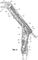
- the head 104 can include a thumbwheel and a socket that can be configured to interface with different tools, including a hex wrench as shown in FIG. 9 .
- the thumbwheel allows a user to change the position of the adjustment body 82 without a tool. Certain embodiments can include just the thumbwheel or just the socket.
- a cover 105 can optionally be connected to the second arm 30 to block the thumbwheel, so that only a tool can be used to alter the position of the adjustment body 82.
- the cover 105 can be connected to the arm, for example through a snap fit connection that is designed either to be releasable or to be semi-permanent, requiring a component of the cover 105 to be broken or fractured to be removed.
- the second member 88 includes a third set of openings 106 positioned below the second set of openings 94 and the third member 90 includes a fourth set of openings 108.
- the third set 106 of openings and the fourth set of openings 108 align with the second set of openings 70 in the bracket 62 to receive the third pin 72, fixing the adjustment body 82 to the second pulley 52 and allowing movement of the adjustment body 82 to move the second pulley 52.
- the second arm 30 includes a channel or slot no along which the second pulley 52 and the components connected thereto move.
- FIGS. 7 and 8 show the adjustment body 82, and thus the second pulley 52, positioned all the way forward, or toward the distal end of the second arm 30.
- FIG. 7 there is very little or no extension applied to the biasing member 46 so little force is required to move the second arm 30 and only a small load, or in some cases no load, can be supported by the second arm 30 above its lowest position.
- the rotation point of the second pulley 52 when the adjustment body 82 is all the way forward, the rotation point of the second pulley 52 is substantially perpendicular to the second arm axis A1 that passes through the motion joint 32 rotation axis X2 and the second arm 30 rotation axis X1, and the rotation point of the second pulley can be substantially coaxial with the second arm 30 rotation axis X1. With the second pulley 52 positioned at or near the second arm 30 rotation axis X1 there is little to no supporting force supplied by the biasing member 46.
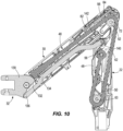
- FIGS. 9 and 10 show the second pulley 52 positioned all the way back, or toward the proximal end of the second arm 30.
- less leverage is required because the load is supported more by the structure of the support arms 22, 30, 34. This results in less resistance to move the adjustment body 82.
- the reward position of the second pulley 52 results in greater leverage on the biasing member 46, requiring a greater downward force to overcome the tension and therefore supporting a greater load.
- the rotation axis of the second pulley 52 is moved away from the second arm 30 rotation axis X1 along an adjustment axis A2 that has an angle offset from the second arm axis A1.
- the support system 30 can incorporate an indicator to show the position of the adjustment body 82 to user.
- the third member 90 includes a projection 112 that extends through a first slot in the first member 86 and a second slot in the second member 88.
- the projection 112 acts as a visual indicator and is visible through a transparent window 114 in the second arm 30.
- the projection 112 can include coloring or other marking that increases its visibility, and indicates to a user the position of the adjustment body 82.
- the projection 112 can include side pins that move in slots on the second arm 30 to keep the motion of the projection 112 parallel with the window 114, and allows the at least a portion of the third member 90 to pivot as it is moved along the adjustment axis A2.
- the first member 86 can include a boss 118 or other projection that mates with a depression or opening in the second member 88 to align the first and second members 86, 88.
- various exemplary embodiments can be directed to a method of balancing a load by adjusting the amount of counterforce provided by the biasing member 46.
- the method can include attaching a display device to the support system 20 and adjusting the biasing member to balance the weight of the display device as discussed above.
- FIGS. 7 and 8 also show the second arm 30 being moved from a first, raised position to a second, lowered position.
- the orientation of the motion joint 32 is held relatively constant by rotation of the motion joint 32 relative to the second arm 30.
- the motion joint 32 includes connecting body 130 rotatable about a bearing member 132.
- a pivot arm 134 has a first end rotatably connected to the motion joint 32, for example about a first pivot arm pin 136, and a second end rotatably connected to a second pivot arm pin 140 that is connected to the first arm 22.
- the pivot arm 134 can be a rigid, unitary member.
- a guard 138 can be provided between the pivot arm 134 and the second pulley 52.
- the pivot arm 134 causes movement of the connecting body 130 about the bearing member 132.
- the motion joint 32 rotated in the clockwise direction (as viewed in the orientation shown in FIGS. 7 and 8 ) to keep the orientation of the connecting body 130 substantially constant. This can reduce or prevent tilting of a display connected to the support relative to its original plane.
- the biasing member 46 is formed from an elastic material, for example a molded thermoplastic material, for example a thermoplastic copolyester elastomer. After molding, the biasing member 46 can have an initial length that is less than the final length of the biasing member 46 when it is positioned in the first and second arms 22, 30. As used herein, the term final length can mean any length approximately in the range from the minimum final length to the maximum final length as the length of the biasing member 46 is varied by the adjustment mechanism 80. The biasing member 46 can then undergo a treatment, where a force is applied to stretched the biasing member 46 a plurality of times to a stretch length that is greater than the final length and then relaxed.
- an elastic material for example a molded thermoplastic material, for example a thermoplastic copolyester elastomer.
- the distance of the stretch length and the amount of times the biasing member 46 is stretched and relaxed can vary depending on the material, the dimensions of the biasing member 46, and the final spring force range required for the biasing member 46. This treatment causes orientation of the elastomer molecules that results in a more consistent, repeatable resultant force from the biasing member and increased life.
- the biasing member 46 can include a first section 150 having a first cross-sectional configuration and a second section 152 having a second cross-sectional configuration as best shown in FIGS. 11 and 12 .
- the first section 150 can extend from the first end portion 48 to a region distal of the second pulley 52.
- the second section 152 can extend from or near the second portion 54 to a region distal of the second pulley 52.
- Other sections positioned between, before, or after the first and second sections 150, 152 can also be used.
- the shape and cross sectional configuration of the first section 150 is substantially constant while the shape and the cross sectional configuration of the second section is different from the first section and varies through at least a portion of the second section.
- the cross sectional area of the biasing member 46 between the first end portion 48 and the second end portion 54 can remain substantially constant.
- the second section 152 can have one dimension that tapers in a first direction while another dimension widens in the first direction.
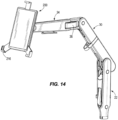
- FIGS. 13-15 show a tablet mount 200 having an adjustable mounting portion 210 that is connected to the third arm 34.
- the mounting portion 210 can include a ball joint 212 and a set screw 214.
- One or more extendable arms 216 are provided to receive different sized tablets.
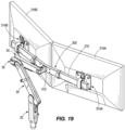
- FIGS. 16-18 show a dual support 300 having a bar 310 with a rotatable mounting portion 310 that is connected to the third arm 34.
- First and second mounting plates 314A, 314B are slidably connected to the bar 310 to support two displays 316A, 316B as best shown in FIG. 19 .
- Providing accessories that mount directly to the third arm 34, as opposed to the mounting head 38 or VESA plate 40 helps reduce the weight and space requirements of the support system 20.
- the terms “front,” “rear,” “upper,” “lower,” “upwardly,” “downwardly,” and other orientational descriptors are intended to facilitate the description of the exemplary embodiments of the present invention, and are not intended to limit the structure of the exemplary embodiments of the present invention to any particular position or orientation.
- Terms of degree, such as “substantially” or “approximately” are understood by those of ordinary skill to refer to reasonable ranges outside of the given value, for example, general tolerances associated with manufacturing, assembly, and use of the described embodiments.
Landscapes
- Engineering & Computer Science (AREA)
- General Engineering & Computer Science (AREA)
- Mechanical Engineering (AREA)
- Devices For Indicating Variable Information By Combining Individual Elements (AREA)
- Casings For Electric Apparatus (AREA)
Description
- Various exemplary embodiments relate to a support system used to moveably support electronic displays such as monitors or TVs.
- Modern screen-based display devices are typically flat-screen monitors such as liquid crystal display (LCD) or plasma screen displays. Such devices can be mounted on elevated support devices such as a support arm which can then be secured to a surface such that the flat-screen monitor is held above or in front of the surface.
DE 90 04 843 U1 discloses a reading aid with an adjustable bookkeeping plate.
FR 2 922 624 A1
US 2005/011045 A1 discloses a hinge including a bracket, two fixing seats pivotally connected to the bracket, at least one base, at least one first arm pivotally connected between the at least one base and the at least one fixing seat and at least one second arm pivotally connected between the at least one base and the at least one fixing seat.
US 2007/102596 A1 discloses a support assembly for a liquid crystal display including a main frame, a connecting seat mounted to an end of the main frame, a coupler mounted to the connecting seat, a liquid crystal display mounting member mounted to the connecting seat, and a tension adjusting device.
US 5 435 515 A discloses a support arm of a camera stabilizing device which is provided with a tensioning assembly which is mated to the support arm in a fashion which permits adjustment of the geometric relationship between the end points of the tensioning assembly and the remaining structures which comprise the support arm. - According to an embodiment of the present invention, a support system for a display device is provided according to
claim 1. - According to an example, a support system for a display device includes a support structure having a first arm and a second arm rotatably connected to the first arm about a first axis. A biasing system includes a biasing member extending between the first arm and the second arm. The biasing member provides a force to balance a load applied to the support structure. An adjustment mechanism connected to the biasing system includes a moveable fulcrum for adjusting the force provided by the biasing member.
- The present invention further provides a method of adjusting a support system for display device according to claim 13.
- The aspects and features of various exemplary embodiments will be more apparent from the description of those exemplary embodiments taken with reference to the accompanying drawings, in which:
-
FIG. 1 is a rear perspective view of an exemplary support system; -
FIG. 2 is a bottom perspective view of an exemplary link member and gear assembly; -
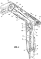
FIG. 3 is a front perspective view of the first arm, second, arm, and motion joint ofFIG. 1 , with half of the first and second arm housing removed, and the second arm in a raised position; -
FIG. 4 is a side perspective view ofFIG. 3 , with the second arm in a lowered position; -
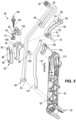
FIG. 5 is an exploded view of the second arm, biasing system, and adjustment mechanismFIG. 3 ; -
FIG. 6A is a rear perspective view of an exemplary adjustment mechanism; -
FIG. 6B is a side sectional view ofFIG. 6A ; -
FIG. 7 is a side sectional view ofFIG. 3 with the second arm in the raised position and the adjustment mechanism in a forward position; -
FIG. 8 is a side sectional view ofFIG. 3 with the second arm in the lowered position and the adjustment mechanism in a forward position; -
FIG. 9 is a side sectional view ofFIG. 3 with the second arm in the raised position and the adjustment mechanism in a rearward position; -
FIG. 10 is a side sectional view ofFIG. 3 with the second arm in the lowered position and the adjustment mechanism in a reward position; -
FIG. 11 is a side view of an exemplary biasing member; -
FIG. 12 is a top view ofFIG. 10 ; -
FIG. 13 is a rear perspective view of an exemplary tablet mount; -
FIG. 14 is a front perspective view of the tablet mount connected to the support system arms; -
FIG. 15 is a side view ofFIG. 14 ; -
FIG. 16 is a front perspective view of a dual mount; -
FIG. 17 is a rear perspective view ofFIG. 16 ; -
FIG. 18 is a front perspective view of the dual mount connected to the support system arms; and -
FIG. 19 is a rear perspective view ofFIG. 18 with displays connected to the dual mount. -
FIG. 1 shows an exemplary embodiment of a support system 20 for a display that includes afirst arm 22 having amounting portion 24 at a proximal end for rotatably connecting the support system to a surface (not shown). As best shown inFIG.2 , themounting portion 24 can include acylindrical cavity 28 for slidably receiving a mounting member that can be connected to various surfaces or supports, such as desk, tables, walls, etc. as would be understood by one of ordinary skill in the art. A proximal portion of asecond arm 30 is rotatably connected to a distal portion of thefirst arm 22. Amotion joint 32 is rotatably connected to the distal potion of thesecond arm 30. A proximal portion of athird arm 34 is rotatably connected to themotion joint 32 by alink member 36. Amounting head 38 is rotatably connected to a distal portion of thethird arm 34 and connected to display mount 40, for example a VESA type display mount. Each of the first, second, andthird arms more clips 43 can be positioned on the one or more of the arms to organize and retain cables running to the display. Thefirst arm 22,second arm 30,motion joint 32,third arm 34 andlink member 36 make up an exemplary embodiment of a support structure, although other variations of support structures may also be used. - As best shown in
FIG. 1 , thefirst arm 22 can rotate relative to the support or surface about a first vertical axis Y1. Thesecond arm 30 can rotate relative to thefirst am 22 about a first horizontal axis X1. Themotion joint 32 can rotate relative to thesecond arm 30 about a second horizontal axis X2. Thelink member 36 can rotate relative to themotion joint 32 about a second vertical axis Y2 and thethird arm 34 can rotate relative to thelink member 36 about a third vertical axis Y3. Themounting head 38 can rotate relative to thethird arm 34 about a fourth vertical axis Y4 and can include a pivoting portion that rotates about a third horizontal axis X3. In an exemplary embodiment the third horizontal axis X3 is a virtual axis spaced from the pivoting portion to extend either through the display mount 40 or a portion of a display connected thereto. The display mount 40 can include aturntable portion 42 that is capable of rotating about an applicate axis Z1. - As best shown in
FIG. 2 , thelink member 36 can contain a gear assembly that limits rotation of thethird arm 34 relative to thesecond arm 30. For example, afirst gear 37A having a first set of teeth and asecond gear 37B having a second set of teeth can be rotatably connected inside of thelink member 36. The first teeth and second teeth mesh with one another, and the end of the teeth form a stop that prevents thethird arm 34 from contacting thesecond arm 30 during rotation. The gear assembly also helps to limit or prevent unwanted rotation of thethird arm 24 relative to thesecond arm 30. -
FIGS. 3-10 show an exemplary embodiment of internal components of the support system 20 which include abiasing system 44 that provides a force to offset the torque created by the weight of a load attached to the support system, for example a monitor connected to the display mount 40. The biasingsystem 44 includes a biasingmember 46 that extends from thefirst arm 22 to the distal portion of thesecond arm 30. The biasingmember 46 extends from afirst end portion 48 anchored in thefirst arm 22, around afirst pulley 50 positioned in thefirst arm 22, around asecond pulley 52 positioned in thesecond arm 30, and to asecond end portion 54 anchored in thesecond arm 30. In an exemplary embodiment, thefirst end portion 48 includes a loop member that is connected in thefirst arm 22 by afirst pin 56 and thesecond end portion 54 includes an enlarged head that fits into achamber 58 formed in thesecond arm 30. - The
first pulley 50 can include a wheel and one or more bearings connected to thefirst arm 22 by asecond pin 60. Thefirst pulley 50 is positioned below thefirst end portion 48 so that the biasingmember 46 includes a portion extending away from thesecond arm 30 and a portion extending toward thesecond arm 30. Abracket 62 extends between thefirst end portion 48 of the biasingmember 46 and thesecond pulley 52. Thebracket 62 includes afirst side 64 and asecond side 66. A first set ofopenings 68 extends through the bottom of the first andsecond sides first pin 56 and a second set ofopenings 70 extends through the top of the first andsecond sides third pin 72. Thefirst end portion 48 of the biasingmember 46 is positioned between the first andsecond sides openings 68. Thesecond pulley 52 can include a wheel and one or more bearings, and is positioned between the first andsecond sides third pin 72. - The support system 20 can also include an
adjustment mechanism 80 as best shown inFIGS. 3-6B . Theadjustment mechanism 80 is configured to adjust the tension of the biasingmember 46 to increase or decrease the amount of counter force provided by the biasingsystem 44. In an exemplary embodiment theadjustment mechanism 80 includes anadjustment body 82 and amovement mechanism 84. Through adjustment of themovement mechanism 84, theadjustment body 82 can change the position of thesecond pulley 52, altering the position at which thesecond pulley 52 acts on the biasingmember 46. In essence, thesecond pulley 52 acts a fulcrum point to balance a load connected to the support system 20, and moving thesecond pulley 52 adjusts the amount of force needed to move thesecond arm 30. - The
adjustment body 82 includes afirst member 86, asecond member 88, and athird member 90. Thefirst member 86 has a body including a top wall and a pair of sidewalls in a substantially U-shaped configuration. Thefirst member 90 sidewalls include a first set of alignedopenings 92. Thesecond member 88 has a body including a top wall and a pair of sidewalls in a substantially U-shaped configuration. Thesecond member 88 sidewalls include a second set of alignedopenings 94. Thethird member 90 has a body including aconcave receiving area 96. When assembled, the first set ofopenings 92, second set ofopenings 94, and theconcave receiving area 96 align to receive anadjustment pin 98. Theadjustment pin 98 has anopening 100 for receiving themovement mechanism 84. - In an exemplary embodiment, the
movement mechanism 84 includes a threadedportion 102 and ahead 104 that is accessible through thesecond arm 30. The threadedportion 102 engages theopening 100 in theadjustment pin 98 and rotation of thehead 104 causes movement of theadjustment pin 98, which causes movement of the first, second, andthird members head 104 can include a thumbwheel and a socket that can be configured to interface with different tools, including a hex wrench as shown inFIG. 9 . The thumbwheel allows a user to change the position of theadjustment body 82 without a tool. Certain embodiments can include just the thumbwheel or just the socket. Acover 105 can optionally be connected to thesecond arm 30 to block the thumbwheel, so that only a tool can be used to alter the position of theadjustment body 82. Thecover 105 can be connected to the arm, for example through a snap fit connection that is designed either to be releasable or to be semi-permanent, requiring a component of thecover 105 to be broken or fractured to be removed. - As best shown in
FIG. 5 , thesecond member 88 includes a third set ofopenings 106 positioned below the second set ofopenings 94 and thethird member 90 includes a fourth set ofopenings 108. When assembled, thethird set 106 of openings and the fourth set ofopenings 108 align with the second set ofopenings 70 in thebracket 62 to receive thethird pin 72, fixing theadjustment body 82 to thesecond pulley 52 and allowing movement of theadjustment body 82 to move thesecond pulley 52. Thesecond arm 30 includes a channel or slot no along which thesecond pulley 52 and the components connected thereto move. -
FIGS. 7 and8 show theadjustment body 82, and thus thesecond pulley 52, positioned all the way forward, or toward the distal end of thesecond arm 30. In the position ofFIG. 7 , there is very little or no extension applied to the biasingmember 46 so little force is required to move thesecond arm 30 and only a small load, or in some cases no load, can be supported by thesecond arm 30 above its lowest position. In an exemplary embodiment, when theadjustment body 82 is all the way forward, the rotation point of thesecond pulley 52 is substantially perpendicular to the second arm axis A1 that passes through the motion joint 32 rotation axis X2 and thesecond arm 30 rotation axis X1, and the rotation point of the second pulley can be substantially coaxial with thesecond arm 30 rotation axis X1. With thesecond pulley 52 positioned at or near thesecond arm 30 rotation axis X1 there is little to no supporting force supplied by the biasingmember 46. -
FIGS. 9 and10 show thesecond pulley 52 positioned all the way back, or toward the proximal end of thesecond arm 30. In the raised position ofFIG. 9 , less leverage is required because the load is supported more by the structure of thesupport arms adjustment body 82. When thesecond arm 30 is rotated into a lower position as shown inFIG. 9 , the reward position of thesecond pulley 52 results in greater leverage on the biasingmember 46, requiring a greater downward force to overcome the tension and therefore supporting a greater load. As best shown inFIG. 9 , the rotation axis of thesecond pulley 52 is moved away from thesecond arm 30 rotation axis X1 along an adjustment axis A2 that has an angle offset from the second arm axis A1. - The
support system 30 can incorporate an indicator to show the position of theadjustment body 82 to user. In an exemplary embodiment, thethird member 90 includes aprojection 112 that extends through a first slot in thefirst member 86 and a second slot in thesecond member 88. Theprojection 112 acts as a visual indicator and is visible through atransparent window 114 in thesecond arm 30. Theprojection 112 can include coloring or other marking that increases its visibility, and indicates to a user the position of theadjustment body 82. Theprojection 112 can include side pins that move in slots on thesecond arm 30 to keep the motion of theprojection 112 parallel with thewindow 114, and allows the at least a portion of thethird member 90 to pivot as it is moved along the adjustment axis A2. Thefirst member 86 can include a boss 118 or other projection that mates with a depression or opening in thesecond member 88 to align the first andsecond members - In light of the above, various exemplary embodiments can be directed to a method of balancing a load by adjusting the amount of counterforce provided by the biasing
member 46. The method can include attaching a display device to the support system 20 and adjusting the biasing member to balance the weight of the display device as discussed above. -
FIGS. 7 and8 also show thesecond arm 30 being moved from a first, raised position to a second, lowered position. During rotation of thesecond arm 30, the orientation of the motion joint 32 is held relatively constant by rotation of the motion joint 32 relative to thesecond arm 30. As best shown inFIGS. 3 ,4 and7-10 , the motion joint 32 includes connectingbody 130 rotatable about a bearingmember 132. Apivot arm 134 has a first end rotatably connected to the motion joint 32, for example about a firstpivot arm pin 136, and a second end rotatably connected to a secondpivot arm pin 140 that is connected to thefirst arm 22. Thepivot arm 134 can be a rigid, unitary member. Aguard 138 can be provided between thepivot arm 134 and thesecond pulley 52. - As the
second arm 30 rotates relative thefirst arm 22, thepivot arm 134 causes movement of the connectingbody 130 about the bearingmember 132. For example, when thesecond arm 30 is moved from the first position shown inFIG. 7 to the second position shown inFIG. 8 the motion joint 32 rotated in the clockwise direction (as viewed in the orientation shown inFIGS. 7 and8 ) to keep the orientation of the connectingbody 130 substantially constant. This can reduce or prevent tilting of a display connected to the support relative to its original plane. - According to some exemplary embodiments, the biasing
member 46 is formed from an elastic material, for example a molded thermoplastic material, for example a thermoplastic copolyester elastomer. After molding, the biasingmember 46 can have an initial length that is less than the final length of the biasingmember 46 when it is positioned in the first andsecond arms member 46 is varied by theadjustment mechanism 80. The biasingmember 46 can then undergo a treatment, where a force is applied to stretched the biasing member 46 a plurality of times to a stretch length that is greater than the final length and then relaxed. The distance of the stretch length and the amount of times the biasingmember 46 is stretched and relaxed can vary depending on the material, the dimensions of the biasingmember 46, and the final spring force range required for the biasingmember 46. This treatment causes orientation of the elastomer molecules that results in a more consistent, repeatable resultant force from the biasing member and increased life. - Extending between the
first end portion 48 and thesecond end portion 54 the biasingmember 46 can include afirst section 150 having a first cross-sectional configuration and asecond section 152 having a second cross-sectional configuration as best shown inFIGS. 11 and 12 . Thefirst section 150 can extend from thefirst end portion 48 to a region distal of thesecond pulley 52. Thesecond section 152 can extend from or near thesecond portion 54 to a region distal of thesecond pulley 52. Other sections positioned between, before, or after the first andsecond sections - In an exemplary embodiment, the shape and cross sectional configuration of the
first section 150 is substantially constant while the shape and the cross sectional configuration of the second section is different from the first section and varies through at least a portion of the second section. In some embodiments, although the first and second sections have different cross section configurations, the cross sectional area of the biasingmember 46 between thefirst end portion 48 and thesecond end portion 54 can remain substantially constant. For example, thesecond section 152 can have one dimension that tapers in a first direction while another dimension widens in the first direction. - Different accessory components can be connected to the
third arm 34 in place of the mountinghead 38.FIGS. 13-15 show atablet mount 200 having anadjustable mounting portion 210 that is connected to thethird arm 34. The mountingportion 210 can include a ball joint 212 and aset screw 214. One or moreextendable arms 216 are provided to receive different sized tablets.FIGS. 16-18 show adual support 300 having abar 310 with a rotatable mountingportion 310 that is connected to thethird arm 34. First and second mountingplates bar 310 to support twodisplays FIG. 19 . Providing accessories that mount directly to thethird arm 34, as opposed to the mountinghead 38 or VESA plate 40 helps reduce the weight and space requirements of the support system 20. - The foregoing detailed description of the certain exemplary embodiments has been provided for the purpose of explaining the principles of the invention and its practical application, thereby enabling others skilled in the art to understand the invention for various embodiments and with various modifications as are suited to the particular use contemplated. This description is not necessarily intended to be exhaustive or to limit the invention to the exemplary embodiments disclosed. Any of the embodiments and/or elements disclosed herein may be combined with one another to form various additional embodiments not specifically disclosed. Accordingly, additional embodiments are possible and are intended to be encompassed within this specification and the scope of the appended claims. The specification describes specific examples to accomplish a more general goal that may be accomplished in another way.
- As used in this application, the terms "front," "rear," "upper," "lower," "upwardly," "downwardly," and other orientational descriptors are intended to facilitate the description of the exemplary embodiments of the present invention, and are not intended to limit the structure of the exemplary embodiments of the present invention to any particular position or orientation. Terms of degree, such as "substantially" or "approximately" are understood by those of ordinary skill to refer to reasonable ranges outside of the given value, for example, general tolerances associated with manufacturing, assembly, and use of the described embodiments.
Claims (13)
- A support system (20) for a display device comprising:a first arm (22) having a lower connection member (24);a second arm (30) rotatably connected to the first arm (22) about a first axis (X1);a joint (32) rotatably connected to the second arm (30) about a second axis (X2); anda biasing system (44) including a biasing member (46) having a first end (48) positioned in the first arm (22) and a second end (54) positioned in the second arm (30), the biasing member (46) providing a force to balance a load applied to the second arm (30), characterized in thatthe biasing member (46) includes an elastomeric spring including a thermoplastic material that has undergone a pre-stretch treatment.
- The support system (20) of claim 1, wherein the elastomeric spring includes a first end portion (150), a second end portion (152), a first portion (150) having a first cross-section and a second portion (152) having a second cross-section, wherein the shape of the second cross-section is different than the shape of the first cross-section and the area of the first cross-section is the same as the area of the second cross-section.
- The support system (20) of any preceding claim, wherein the biasing system (44) includes a first pulley (50) positioned in the first arm (22), a second pulley (52) positioned in the second arm (30), and a bracket (62) having a first portion positioned in the first arm (22) and a second portion positioned in the second arm (30).
- The support system (20) of claim 3, wherein the first end (48) of the biasing member (46) is connected to the bracket (62).
- The support system (20) of claim 4, wherein the biasing member (46) engages the first pulley (50) and the second pulley (52), and connects to the bracket (62) at a position between the first pulley (50) and the second pulley (52).
- The support system (20) of any preceding claim, further comprising an adjustment mechanism (80) connected to the biasing system (44).
- The support system (20) of claim 6, comprising:a support structure including the first arm (22) and the second arm (30), whereinthe adjustment mechanism (80) includes a moveable fulcrum for adjusting the force provided by the biasing member (46).
- The supports system of claim 7, wherein the fulcrum is moveable away from the first axis (X1) to increase the force provided by the biasing member (46).
- The support system (20) of claim 7 or claim 8, wherein a third axis extends through the second arm (30) between the first axis (X1) and the second axis (X2), and the fulcrum moves along a fourth axis that intersects the third axis at an oblique angle.
- The supports system of any one of claims 7 to 9, wherein the adjustment mechanism (80) includes an adjustment body (82) connected to the fulcrum and a rotatable movement mechanism (84).
- The supports system of claim 10, wherein the adjustment body (82) includes a first member (86), a second member (88) connected to the first member (86), and a third member (90) connected to the second member (88).
- The support system (20) of any one of claims 7 to 11, wherein the fulcrum includes a rotatable pulley engaging the biasing member (46).
- A method of adjusting a support system (20) for display device comprising:attaching a display device to a support system (20) including a first arm (22), a second arm (30) rotatably connected to the first arm (22) about a first axis (X1), a biasing member (46) extending between the first arm (22) and the second arm (30) and providing a force; andadjusting an adjustment mechanism (80) connected to the biasing system (44) to move the position of a fulcrum to adjust the force provided by the biasing member (46),wherein the biasing member (46) includes an elastomeric spring including a thermoplastic material that has undergone a pre-stretch treatment.
Applications Claiming Priority (2)
| Application Number | Priority Date | Filing Date | Title |
|---|---|---|---|
| US15/331,090 US10845000B2 (en) | 2016-10-21 | 2016-10-21 | Display support system |
| PCT/GB2017/053174 WO2018073601A1 (en) | 2016-10-21 | 2017-10-20 | Display support system |
Publications (3)
| Publication Number | Publication Date |
|---|---|
| EP3529529A1 EP3529529A1 (en) | 2019-08-28 |
| EP3529529C0 EP3529529C0 (en) | 2023-09-20 |
| EP3529529B1 true EP3529529B1 (en) | 2023-09-20 |
Family
ID=60190894
Family Applications (1)
| Application Number | Title | Priority Date | Filing Date |
|---|---|---|---|
| EP17791445.4A Active EP3529529B1 (en) | 2016-10-21 | 2017-10-20 | Display support system |
Country Status (6)
| Country | Link |
|---|---|
| US (1) | US10845000B2 (en) |
| EP (1) | EP3529529B1 (en) |
| JP (1) | JP7200099B2 (en) |
| CN (1) | CN109952465B (en) |
| AU (1) | AU2017346515B2 (en) |
| WO (1) | WO2018073601A1 (en) |
Families Citing this family (29)
| Publication number | Priority date | Publication date | Assignee | Title |
|---|---|---|---|---|
| US11131423B2 (en) * | 2016-03-07 | 2021-09-28 | Southco, Inc. | Display support arm assembly for mounting a display |
| US10233618B2 (en) * | 2016-06-03 | 2019-03-19 | Kohler Co. | Faucet including control arm |
| USD830371S1 (en) * | 2016-10-21 | 2018-10-09 | Colebrook Bosson & Saunders (Products) Limited | Support arm |
| BR212019008386Y1 (en) | 2016-10-26 | 2023-12-19 | Southco, Inc | COMPRESSION LATCH WITH KEY RETENTION |
| WO2018144913A1 (en) * | 2017-02-02 | 2018-08-09 | Brunson Instrument Company | Counterbalanced support system and method of use |
| USD877744S1 (en) * | 2017-03-24 | 2020-03-10 | Loctek Inc. | Mounting arm for display stand |
| USD891834S1 (en) | 2017-10-06 | 2020-08-04 | Brunson Instrument Company | Stand and counterbalanced support |
| USD859422S1 (en) * | 2018-03-06 | 2019-09-10 | GCX Corporation | Support arm |
| USD870737S1 (en) * | 2018-03-06 | 2019-12-24 | GCX Corporation | Support arm |
| JP7028702B2 (en) * | 2018-04-17 | 2022-03-02 | Ckd株式会社 | Arm type assist device |
| US10323791B1 (en) * | 2018-06-06 | 2019-06-18 | C. D. Great Furniture Co., Ltd. | Displacement structure for a support frame |
| CN109027636B (en) * | 2018-09-29 | 2021-10-26 | 明基智能科技(上海)有限公司 | Multifunctional support frame |
| EP3685092B1 (en) | 2018-12-10 | 2024-02-14 | Colebrook Bosson & Saunders (Products) Limited | Display support structure |
| USD935458S1 (en) * | 2018-12-10 | 2021-11-09 | Colebrook Bosson & Saunders (Products) Limited | Support structure |
| GB2580417A (en) * | 2019-01-11 | 2020-07-22 | Arrow Group Global Ltd | Display device support arm |
| US11112057B2 (en) * | 2019-07-10 | 2021-09-07 | Ergotron, Inc. | Display mounting system and method |
| US11320090B2 (en) * | 2019-11-21 | 2022-05-03 | Oasys Healthcare Corporation | Arm linkage for device bearing spring arms |
| USD922394S1 (en) * | 2020-07-22 | 2021-06-15 | Hangzhou Yue Fu Si Supply Chain Management Co., Ltd | Monitor mount |
| US11174980B1 (en) * | 2020-10-07 | 2021-11-16 | Amber Tran | Dual telescopic pointer with adjustable ball joints |
| CN112682432B (en) * | 2020-11-12 | 2022-08-09 | 中国航空工业集团公司北京航空精密机械研究所 | Internal friction couple moment balancing device for rotary joint |
| CN112628547A (en) * | 2020-12-15 | 2021-04-09 | 汯云科技(武汉)有限公司 | Automatic transaction system for futures |
| WO2022177575A1 (en) * | 2021-02-22 | 2022-08-25 | Ideal Industries, Inc. | Support system for computing device displays |
| USD962903S1 (en) * | 2021-04-29 | 2022-09-06 | Ningbo Tuotuo River Design Company | Microphone stand |
| US11933450B2 (en) | 2021-05-12 | 2024-03-19 | Colebrook Bosson & Saunders (Products) Limited | Tilt head for high load display support system |
| USD1013699S1 (en) * | 2021-08-20 | 2024-02-06 | Ningbo Kaisheng Metal Manufacturing Co., Ltd. | Computer LCD monitor stand |
| USD1021889S1 (en) * | 2022-01-13 | 2024-04-09 | Ningbo Tuotuo River Design Company | Microphone holder |
| USD1005995S1 (en) * | 2022-02-14 | 2023-11-28 | Syncmold Enterprise Corp. | Supporting frame |
| CN114636079A (en) * | 2022-03-18 | 2022-06-17 | 东莞市擎易五金科技有限公司 | Display screen support that can smooth-going adjust |
| USD1030725S1 (en) * | 2022-08-03 | 2024-06-11 | Ningbo Tuotuo River Design Company | Support arm |
Family Cites Families (133)
| Publication number | Priority date | Publication date | Assignee | Title |
|---|---|---|---|---|
| US1806724A (en) | 1931-05-26 | Gun mottnt fob aibcbaft | ||
| US899769A (en) | 1908-03-09 | 1908-09-29 | Henry Tideman | Mechanism of the lazy-tong genus. |
| US2038045A (en) * | 1935-05-02 | 1936-04-21 | Astrup Company | Tensioned awning arm |
| GB1392605A (en) | 1971-09-16 | 1975-04-30 | Oram J A | Adjustable articulated support |
| US4055329A (en) | 1976-07-19 | 1977-10-25 | Leisure Manufacturing Co., Inc. | Scissors jack |
| US4234150A (en) | 1979-02-02 | 1980-11-18 | Spar Aerospace Limited | Mechanical arm assembly |
| US4266747A (en) * | 1979-07-26 | 1981-05-12 | Positioning Devices, Incorporated | Equipoised articulated support arm |
| US4393541A (en) * | 1980-02-19 | 1983-07-19 | General Dynamics Corporation/Convair Div. | Hinge for deployable structures self locking hinge |
| DE3173714D1 (en) * | 1980-09-18 | 1986-03-20 | Zeiss Carl Fa | Adjustable stand for optical observing units |
| US4483070A (en) * | 1982-09-21 | 1984-11-20 | Joane G. Tannehill | Portable backpacked cutter |
| US4589621A (en) | 1984-01-03 | 1986-05-20 | International Business Machines Corporation | Ergonomic monitor stand |
| US4545555A (en) | 1984-07-02 | 1985-10-08 | Koch Mark B | Adjustable arm member for use with a lamp or the like |
| US4768762A (en) * | 1985-05-15 | 1988-09-06 | Lund Kurt O | Means and method to counterbalance the weight of a body |
| US4685648A (en) * | 1985-05-17 | 1987-08-11 | Bausch & Lomb Incorporated | Counterbalancing apparatus for use in an optical instrument |
| US4770384A (en) * | 1986-07-28 | 1988-09-13 | Matsushita Electric Works, Ltd. | Movable stand |
| US4736490A (en) * | 1986-10-29 | 1988-04-12 | The United State Of America As Represented By The Administrator Of The National Aeronautics And Space Administration | Locking hinge |
| US4834329A (en) | 1987-05-29 | 1989-05-30 | Michael Delapp | Monitor support for a terminal |
| US4943020A (en) * | 1987-09-17 | 1990-07-24 | Schlumberger Technologies, Inc. | Manipulator apparatus |
| IT1217683B (en) * | 1988-05-20 | 1990-03-30 | Artemide Spa | ARTIFICIAL LIGHTING EQUIPMENT WITH ARTICULATED ARMS |
| DE9004843U1 (en) | 1990-04-28 | 1990-07-12 | Bechtel, Benjamin, 6337 Leun | Reading aid with an adjustable book holder |
| US5170975A (en) | 1991-06-06 | 1992-12-15 | Alan Chadwick | Articulated arm with spring for counterbalancing |
| US5435515A (en) | 1992-09-15 | 1995-07-25 | Garrett W. Brown | Adustable, iso-elastic support apparatus |
| US5241716A (en) | 1992-10-07 | 1993-09-07 | Baby Trend, Inc. | Foldable play yard having meshing hinge gear frame locks |
| US5339233A (en) * | 1993-05-12 | 1994-08-16 | Roger Yang | Lamp assembly |
| US5538214A (en) | 1994-07-27 | 1996-07-23 | Sinila; Alexander | Locking accessory support apparatus |
| US5842312A (en) * | 1995-03-01 | 1998-12-01 | E*Sorb Systems | Hysteretic damping apparati and methods |
| US5609316A (en) * | 1995-09-05 | 1997-03-11 | Tigliev; George S. | Suspension system for surgical microscope |
| US5746404A (en) * | 1996-02-15 | 1998-05-05 | Merko; Andrew V. | Apparatus for counterbalancing equipment |
| FR2746151B1 (en) * | 1996-03-15 | 1998-05-22 | DEVICE FOR THE PROTECTION AND GUIDE OF AN ASSOCIATED ELONGATED COMPONENT, AT THE JOINT, WITH TWO RIGID ELEMENTS JOINTED ONE TO THE OTHER, AND THEIR INDUSTRIAL APPLICATIONS | |
| DE19711572B4 (en) * | 1997-03-20 | 2006-09-07 | Carl Zeiss | Surgical microscope stand |
| DE29709093U1 (en) | 1997-05-23 | 1997-07-17 | Fritz Sträter GmbH, 58540 Meinerzhagen | Articulated arm for office equipment |
| US6227508B1 (en) | 1999-02-12 | 2001-05-08 | Cook Specialty Company | Adjustable support apparatus |
| TW404638U (en) | 1999-03-18 | 2000-09-01 | Chiou Huei Min | Plane monitor used foot seat |
| US6113046A (en) * | 1999-08-26 | 2000-09-05 | Wang; James | Angle-adjustable, auto-locking apparatus support |
| JP4495284B2 (en) | 1999-11-17 | 2010-06-30 | 株式会社岡村製作所 | Display support device |
| DE10142564A1 (en) | 2000-09-30 | 2002-04-11 | Zeiss Carl | Support for mounting a medical equipment, e.g. for holding an operation microscope |
| DE10051892A1 (en) * | 2000-10-19 | 2002-04-25 | Zeiss Carl | Pivot mounting assembly |
| JP2004520550A (en) * | 2001-01-05 | 2004-07-08 | ザハトラー・ゲーエムベーハー・ウント・コ・カーゲー | Camera tripod head with weight compensation |
| US6467936B1 (en) * | 2001-10-03 | 2002-10-22 | Andrew J. Golemba | Adjustable desk lamp |
| US6857610B1 (en) * | 2001-12-10 | 2005-02-22 | John P. Conner | Position adjustable load support mechanism |
| JP2003223238A (en) | 2002-01-28 | 2003-08-08 | Internatl Business Mach Corp <Ibm> | Computer device, monitor unit and support structure of unit facing user |
| DE10210244A1 (en) | 2002-03-08 | 2003-09-18 | Wolfvision Gmbh Goetzis | Articulated arm, in particular for a device for optically recording objects |
| US6663266B2 (en) * | 2002-05-09 | 2003-12-16 | Nan-Jung Huang | Lighting fixture for optionally positioning lamp device |
| US6758585B1 (en) * | 2002-05-29 | 2004-07-06 | Erik S. Chan | Articulated, adjustable stand |
| AU2003204503A1 (en) | 2002-06-07 | 2004-01-08 | Atdec Pty Ltd | Stand for flat panel display |
| US6997422B2 (en) * | 2002-08-21 | 2006-02-14 | Ergotron, Inc. | Stand |
| US6592090B1 (en) * | 2002-08-23 | 2003-07-15 | Chin-Chu Li | Object supporting structure |
| US6672553B1 (en) * | 2002-08-26 | 2004-01-06 | Chin-Chih Lin | Suspension arm |
| US6896230B2 (en) * | 2002-12-30 | 2005-05-24 | Sava Cvek | Equipoise arm assembly |
| US7252277B2 (en) * | 2003-01-17 | 2007-08-07 | Ergotron, Inc. | Support arm |
| JP4234754B2 (en) | 2003-02-21 | 2009-03-04 | ノル・インコーポレイテッド | Mechanical arm with balancing spring |
| US7290744B2 (en) * | 2003-04-03 | 2007-11-06 | Baldasari Alan D | Break-away basketball goal system |
| US6769657B1 (en) * | 2003-04-09 | 2004-08-03 | Min Hwa Huang | Support device for monitor, display or objects |
| AU2003903540A0 (en) | 2003-07-09 | 2003-07-24 | Atdec Pty Ltd | Flat panel display wall mounting system |
| US6889404B2 (en) | 2003-07-18 | 2005-05-10 | Shin Zu Shing Co., Ltd. | Height-adjustable hinge for a liquid crystal display |
| US6899308B2 (en) | 2003-07-31 | 2005-05-31 | Agency For Science, Technology And Research | Passive gravity-compensating mechanisms |
| DE60333403D1 (en) * | 2003-08-01 | 2010-08-26 | Llaza Sa | ARMS FOR AWNINGS |
| US7367376B2 (en) * | 2003-08-05 | 2008-05-06 | Llaza, S.A. | Articulated arm for awnings, with improved elastic effect |
| TWM248211U (en) | 2003-08-06 | 2004-10-21 | Hon Hai Prec Ind Co Ltd | Display support apparatus |
| JP4610914B2 (en) | 2004-03-16 | 2011-01-12 | 株式会社岡村製作所 | Parallel link type equipment support device |
| US7441758B2 (en) | 2004-06-17 | 2008-10-28 | Illinois Tool Works Inc. | Load bearing surface |
| WO2011034882A1 (en) | 2009-09-16 | 2011-03-24 | Illinois Tool Works Inc. | Pre-deformed thermoplastics spring and method of manufacture |
| US20090050760A1 (en) | 2004-07-30 | 2009-02-26 | Atdec Pty Limited | Adjustable mounting for flat panel displays |
| US20060070210A1 (en) * | 2004-09-30 | 2006-04-06 | Gateway | Counter balanced hinge assembly |
| US8199471B2 (en) | 2004-10-05 | 2012-06-12 | Creator Technology B.V. | Rollable display device |
| US20060091274A1 (en) * | 2004-10-29 | 2006-05-04 | Saeb Asamarai | Display screen mounting device and method |
| NL1027626C2 (en) | 2004-11-30 | 2006-05-31 | Vogel S Holding Bv | Device suitable for supporting a component. |
| JP4741846B2 (en) | 2005-01-14 | 2011-08-10 | Necディスプレイソリューションズ株式会社 | Stand for thin display device |
| US7325777B2 (en) | 2005-02-18 | 2008-02-05 | Gordon Daniel Thiessen | Portable articulating tool support |
| CN101287945B (en) * | 2005-04-15 | 2012-01-25 | 加勒特·W·布朗 | Equipoising support apparatus |
| US20060231710A1 (en) * | 2005-04-19 | 2006-10-19 | Yuan-Hsiang Huang | Flat display holder arm |
| US8794579B2 (en) | 2005-06-03 | 2014-08-05 | Steelcase, Inc. | Support arm assembly |
| US20070001076A1 (en) | 2005-06-29 | 2007-01-04 | Saeb Asamarai | Support arm and method with variable counterbalance |
| CN100589209C (en) | 2005-09-06 | 2010-02-10 | 全向装配系统公司 | System and method for mounting panel video display |
| US8342467B2 (en) * | 2005-10-04 | 2013-01-01 | Eric Ronald Stachowski | Apparatus for hand control, pressure amplification, and stabilization of medical and industrial devices |
| US20070102596A1 (en) | 2005-11-08 | 2007-05-10 | Roger Sung | Tension adjusting device of support assembly for liquid crystal display |
| DE102005054010A1 (en) * | 2005-11-10 | 2007-05-24 | Carl Zeiss Surgical Gmbh | Holding device with weight compensation |
| JP4407622B2 (en) * | 2005-11-17 | 2010-02-03 | ソニー株式会社 | Television equipment |
| TW200722827A (en) | 2005-12-14 | 2007-06-16 | Benq Corp | Display |
| JP2007173118A (en) * | 2005-12-22 | 2007-07-05 | Matsushita Electric Works Ltd | Movable arm and design method of the same |
| TWI333098B (en) | 2006-03-03 | 2010-11-11 | Benq Corp | Rotatable apparatus |
| US8465007B2 (en) | 2006-03-22 | 2013-06-18 | Illinois Tool Works Inc. | Load bearing assembly with elastomeric edge |
| TW200739176A (en) * | 2006-04-11 | 2007-10-16 | Fulfil Tech Co Ltd | Supporting apparatus with going up-and-down |
| KR101253569B1 (en) * | 2006-05-09 | 2013-04-11 | 삼성전자주식회사 | Supporting device for display unit |
| KR100710313B1 (en) | 2006-05-26 | 2007-04-23 | 엘지전자 주식회사 | Display device |
| KR100845863B1 (en) | 2006-06-01 | 2008-07-14 | 엘지전자 주식회사 | Monitor stand |
| US8228668B2 (en) | 2006-07-26 | 2012-07-24 | Ergotron, Inc. | Balanced moment lift system and method |
| TWM308357U (en) | 2006-09-12 | 2007-03-21 | Modernsolid Ind Co Ltd | Panel fixing stand for multiple angle adjustment |
| US7748666B2 (en) * | 2006-09-15 | 2010-07-06 | Innovative Office Products, Inc. | Extension arm with moving clevis |
| US20080191400A1 (en) * | 2007-02-09 | 2008-08-14 | Ching-Liaug Liu | Spring formed with an abnormal-shaped cross section specially used as a vehicle shock absorber |
| EP2126459B1 (en) | 2007-03-12 | 2010-11-24 | American Sterilizer Company | Internal cable management system for movable support arm |
| PL384694A1 (en) | 2008-03-14 | 2009-09-28 | Furniture In Motion, Inc. | Display screen head, especially of a flat television screen |
| WO2008134754A2 (en) | 2007-04-30 | 2008-11-06 | Milestone Av Technologies Llc | Automated mounting arm for electronic display |
| TWM324949U (en) | 2007-07-18 | 2008-01-01 | Ming-Hsien Tom Huang | Bracket device |
| TW200910951A (en) | 2007-08-16 | 2009-03-01 | Jarllytec Co Ltd | Support structure and the its tension-adjustment mechanism |
| FR2922624A1 (en) | 2007-10-22 | 2009-04-24 | Pierre Andre Davezac | Damping mechanical arm for e.g. motion picture camera, has truss rods acting on lever arm in structure stretched on each parallelogram or cylinders to compose simplified mechanical structure with high quality iso-elastic end |
| CN101463938B (en) | 2007-12-20 | 2011-07-27 | 鸿富锦精密工业(深圳)有限公司 | Lifting mechanism |
| US20090159768A1 (en) | 2007-12-20 | 2009-06-25 | Oh Sung I | Mount System Utilizing One Motor to Extend/Retract and Tilt a Monitor |
| CN101472432B (en) | 2007-12-27 | 2011-11-30 | 鸿富锦精密工业(深圳)有限公司 | Adjustment mechanism |
| CN101487558B (en) | 2008-01-16 | 2012-01-25 | 鸿富锦精密工业(深圳)有限公司 | Lifting mechanism |
| US7748670B1 (en) | 2008-02-11 | 2010-07-06 | Veldez Steven C | Television rotational support apparatus |
| TWI367670B (en) | 2008-03-11 | 2012-07-01 | Qisda Corp | Height adjustable holding apparatus |
| JP4530071B2 (en) | 2008-04-23 | 2010-08-25 | 船井電機株式会社 | Display screen turning device and television device |
| US8220765B2 (en) | 2008-06-23 | 2012-07-17 | Intuitive Surgical Operations, Inc. | Spring counterbalance for rotating load |
| CN201246581Y (en) | 2008-07-07 | 2009-05-27 | 鸿富锦精密工业(深圳)有限公司 | Support frame |
| CN101661312B (en) | 2008-08-29 | 2012-08-22 | 鸿富锦精密工业(深圳)有限公司 | Display device |
| AU2009298701A1 (en) * | 2008-09-30 | 2010-04-08 | Garrett W. Brown | Biased hinge for equipoising support equipment |
| US8181927B2 (en) | 2009-03-25 | 2012-05-22 | Lenovo (Singapore) Pte. Ltd. | Providing constant counterbalance throughout predetermined range of motion |
| CN102414731B (en) | 2009-04-23 | 2014-01-29 | 松下电器产业株式会社 | Video display device with screen angle adjustment mechanism |
| US9682484B2 (en) * | 2009-07-24 | 2017-06-20 | GM Global Technology Operations LLC | Counterbalance mechanism for end-effector configuration and method of use |
| DE102009060495A1 (en) * | 2009-12-23 | 2011-06-30 | Karl Storz GmbH & Co. KG, 78532 | Holding device for medical instruments |
| US8939438B2 (en) * | 2010-01-08 | 2015-01-27 | Lee Spring Company Llc | Plastic spring and method and apparatus for making the same |
| WO2011100807A1 (en) | 2010-02-22 | 2011-08-25 | Edwin Russell | A support mechanism |
| US20110260017A1 (en) * | 2010-04-23 | 2011-10-27 | Humanscale Corporation | Adjustable Support Arm |
| CN201779131U (en) | 2010-05-27 | 2011-03-30 | 鸿富锦精密工业(深圳)有限公司 | Hinge structure |
| GB2481047A (en) | 2010-06-09 | 2011-12-14 | Colebrook Bosson & Saunders Products Ltd | A mounting system for pivotally mounting a flat screen display |
| US9074721B2 (en) | 2010-06-09 | 2015-07-07 | Alex Lau | Support system |
| US8720838B2 (en) * | 2010-06-09 | 2014-05-13 | Innovative Office Products, Llc | Articulating monitor arm with chain and spring |
| CN101999057B (en) * | 2010-06-09 | 2013-10-16 | 创新办公产品公司 | Hinged monitor arm provided with cable and spring |
| TWI391596B (en) | 2010-08-02 | 2013-04-01 | Ming Hsien Huang | Slidable supporting stand |
| US8864092B2 (en) * | 2010-08-04 | 2014-10-21 | Brian Newville | Television mount assembly |
| CN103079774B (en) * | 2010-09-13 | 2015-03-04 | 丰田自动车株式会社 | Support arm |
| TWI386149B (en) | 2010-12-21 | 2013-02-11 | Alpha Networks Inc | Pivoting assembly with press-fit positioning function |
| US9228696B2 (en) | 2011-03-18 | 2016-01-05 | GCX Corporation | Variable height arm structures, systems, and methods |
| TWI401012B (en) | 2011-03-21 | 2013-07-01 | Pegatron Corp | Support stand |
| US8576553B2 (en) * | 2011-05-17 | 2013-11-05 | Myerchin Enterprises, Inc. | Base with counterweight for display screens |
| US8570723B2 (en) | 2011-05-18 | 2013-10-29 | Myerchin Enterprises, Inc. | Actuated hinge and cable assembly for use with computer display monitors |
| US8801320B2 (en) * | 2012-06-26 | 2014-08-12 | Koncept Technologies Inc. | Self biased joint and method |
| JP2014073322A (en) * | 2012-10-05 | 2014-04-24 | Canon Inc | Radiation generator apparatus |
| CN104033707B (en) | 2013-03-06 | 2016-03-09 | 光宝电子(广州)有限公司 | Screen-supporting device and torque force adjusting mechanism |
| US9266243B2 (en) * | 2013-06-14 | 2016-02-23 | Ergotron, Inc. | Arm locking system |
| EP3217939B1 (en) * | 2014-11-10 | 2021-07-21 | Ondal Medical Systems GmbH | Support joint for a cantilever of a medical stand device |
| CN107110423B (en) * | 2014-11-16 | 2019-03-01 | 加勒特·W·布朗 | Stretch parallelogram arm |
-
2016
- 2016-10-21 US US15/331,090 patent/US10845000B2/en active Active
-
2017
- 2017-10-20 JP JP2019521043A patent/JP7200099B2/en active Active
- 2017-10-20 WO PCT/GB2017/053174 patent/WO2018073601A1/en unknown
- 2017-10-20 AU AU2017346515A patent/AU2017346515B2/en active Active
- 2017-10-20 EP EP17791445.4A patent/EP3529529B1/en active Active
- 2017-10-20 CN CN201780064653.8A patent/CN109952465B/en active Active
Also Published As
| Publication number | Publication date |
|---|---|
| AU2017346515A1 (en) | 2019-05-02 |
| JP2020501175A (en) | 2020-01-16 |
| JP7200099B2 (en) | 2023-01-06 |
| WO2018073601A1 (en) | 2018-04-26 |
| EP3529529C0 (en) | 2023-09-20 |
| US10845000B2 (en) | 2020-11-24 |
| AU2017346515B2 (en) | 2023-04-06 |
| EP3529529A1 (en) | 2019-08-28 |
| US20180112820A1 (en) | 2018-04-26 |
| CN109952465A (en) | 2019-06-28 |
| CN109952465B (en) | 2021-07-06 |
Similar Documents
| Publication | Publication Date | Title |
|---|---|---|
| EP3529529B1 (en) | Display support system | |
| US7395995B2 (en) | Monitor support structure | |
| KR100770983B1 (en) | Monitor | |
| US7669812B2 (en) | Stand for display device | |
| US10753531B2 (en) | Multi-display stand | |
| KR100710313B1 (en) | Display device | |
| US9316346B2 (en) | Support system | |
| US20090101777A1 (en) | Wall mount supporting apparatus of flat panel display device | |
| KR100793754B1 (en) | Display device | |
| KR101135902B1 (en) | Supporting apparatus for display | |
| EP1959185A2 (en) | Supporting device for display apparatus and display apparatus having the same | |
| KR20150104612A (en) | Supporting apparatus | |
| US20240143023A1 (en) | Support structure for display | |
| US20240218958A1 (en) | Tilt head for high load display support system | |
| JPH11338576A (en) | Liquid crystal display support device | |
| WO2021049173A1 (en) | Angle adjustment mechanism, desktop apparatus, and method for assembling angle adjustment mechanism | |
| CN114658997B (en) | Display support | |
| KR200291346Y1 (en) | Supporter for adjusting monitor's position | |
| CN201184485Y (en) | Support and planar display | |
| KR200227925Y1 (en) | Hinge Appratus For LCD Monitor | |
| KR200381244Y1 (en) | Hinge apparatus of LCD monitor | |
| KR20060018584A (en) | Hinge assembly for display device | |
| KR200356161Y1 (en) | Supporter for LCD monitor | |
| GB2529974A (en) | Speaker stand | |
| JP2008099065A (en) | Double-shaft type monitor supporting apparatus |
Legal Events
| Date | Code | Title | Description |
|---|---|---|---|
| STAA | Information on the status of an ep patent application or granted ep patent |
Free format text: STATUS: UNKNOWN |
|
| STAA | Information on the status of an ep patent application or granted ep patent |
Free format text: STATUS: THE INTERNATIONAL PUBLICATION HAS BEEN MADE |
|
| PUAI | Public reference made under article 153(3) epc to a published international application that has entered the european phase |
Free format text: ORIGINAL CODE: 0009012 |
|
| STAA | Information on the status of an ep patent application or granted ep patent |
Free format text: STATUS: REQUEST FOR EXAMINATION WAS MADE |
|
| 17P | Request for examination filed |
Effective date: 20190521 |
|
| AK | Designated contracting states |
Kind code of ref document: A1 Designated state(s): AL AT BE BG CH CY CZ DE DK EE ES FI FR GB GR HR HU IE IS IT LI LT LU LV MC MK MT NL NO PL PT RO RS SE SI SK SM TR |
|
| AX | Request for extension of the european patent |
Extension state: BA ME |
|
| RAP1 | Party data changed (applicant data changed or rights of an application transferred) |
Owner name: COLEBROOK BOSSON & SAUNDERS (PRODUCTS) LIMITED |
|
| DAV | Request for validation of the european patent (deleted) | ||
| DAX | Request for extension of the european patent (deleted) | ||
| STAA | Information on the status of an ep patent application or granted ep patent |
Free format text: STATUS: EXAMINATION IS IN PROGRESS |
|
| 17Q | First examination report despatched |
Effective date: 20220503 |
|
| GRAP | Despatch of communication of intention to grant a patent |
Free format text: ORIGINAL CODE: EPIDOSNIGR1 |
|
| STAA | Information on the status of an ep patent application or granted ep patent |
Free format text: STATUS: GRANT OF PATENT IS INTENDED |
|
| INTG | Intention to grant announced |
Effective date: 20230404 |
|
| GRAS | Grant fee paid |
Free format text: ORIGINAL CODE: EPIDOSNIGR3 |
|
| GRAA | (expected) grant |
Free format text: ORIGINAL CODE: 0009210 |
|
| STAA | Information on the status of an ep patent application or granted ep patent |
Free format text: STATUS: THE PATENT HAS BEEN GRANTED |
|
| AK | Designated contracting states |
Kind code of ref document: B1 Designated state(s): AL AT BE BG CH CY CZ DE DK EE ES FI FR GB GR HR HU IE IS IT LI LT LU LV MC MK MT NL NO PL PT RO RS SE SI SK SM TR |
|
| REG | Reference to a national code |
Ref country code: GB Ref legal event code: FG4D |
|
| REG | Reference to a national code |
Ref country code: CH Ref legal event code: EP |
|
| REG | Reference to a national code |
Ref country code: IE Ref legal event code: FG4D |
|
| REG | Reference to a national code |
Ref country code: DE Ref legal event code: R096 Ref document number: 602017074451 Country of ref document: DE |
|
| U01 | Request for unitary effect filed |
Effective date: 20231020 |
|
| U07 | Unitary effect registered |
Designated state(s): AT BE BG DE DK EE FI FR IT LT LU LV MT NL PT SE SI Effective date: 20231110 |
|
| PG25 | Lapsed in a contracting state [announced via postgrant information from national office to epo] |
Ref country code: GR Free format text: LAPSE BECAUSE OF FAILURE TO SUBMIT A TRANSLATION OF THE DESCRIPTION OR TO PAY THE FEE WITHIN THE PRESCRIBED TIME-LIMIT Effective date: 20231221 |
|
| PGFP | Annual fee paid to national office [announced via postgrant information from national office to epo] |
Ref country code: GB Payment date: 20231123 Year of fee payment: 7 |
|
| PG25 | Lapsed in a contracting state [announced via postgrant information from national office to epo] |
Ref country code: RS Free format text: LAPSE BECAUSE OF FAILURE TO SUBMIT A TRANSLATION OF THE DESCRIPTION OR TO PAY THE FEE WITHIN THE PRESCRIBED TIME-LIMIT Effective date: 20230920 Ref country code: NO Free format text: LAPSE BECAUSE OF FAILURE TO SUBMIT A TRANSLATION OF THE DESCRIPTION OR TO PAY THE FEE WITHIN THE PRESCRIBED TIME-LIMIT Effective date: 20231220 Ref country code: HR Free format text: LAPSE BECAUSE OF FAILURE TO SUBMIT A TRANSLATION OF THE DESCRIPTION OR TO PAY THE FEE WITHIN THE PRESCRIBED TIME-LIMIT Effective date: 20230920 Ref country code: GR Free format text: LAPSE BECAUSE OF FAILURE TO SUBMIT A TRANSLATION OF THE DESCRIPTION OR TO PAY THE FEE WITHIN THE PRESCRIBED TIME-LIMIT Effective date: 20231221 |
|
| U20 | Renewal fee paid [unitary effect] |
Year of fee payment: 7 Effective date: 20240124 |
|
| PG25 | Lapsed in a contracting state [announced via postgrant information from national office to epo] |
Ref country code: IS Free format text: LAPSE BECAUSE OF FAILURE TO SUBMIT A TRANSLATION OF THE DESCRIPTION OR TO PAY THE FEE WITHIN THE PRESCRIBED TIME-LIMIT Effective date: 20240120 |
|
| PG25 | Lapsed in a contracting state [announced via postgrant information from national office to epo] |
Ref country code: ES Free format text: LAPSE BECAUSE OF FAILURE TO SUBMIT A TRANSLATION OF THE DESCRIPTION OR TO PAY THE FEE WITHIN THE PRESCRIBED TIME-LIMIT Effective date: 20230920 |
|
| PG25 | Lapsed in a contracting state [announced via postgrant information from national office to epo] |
Ref country code: SM Free format text: LAPSE BECAUSE OF FAILURE TO SUBMIT A TRANSLATION OF THE DESCRIPTION OR TO PAY THE FEE WITHIN THE PRESCRIBED TIME-LIMIT Effective date: 20230920 Ref country code: RO Free format text: LAPSE BECAUSE OF FAILURE TO SUBMIT A TRANSLATION OF THE DESCRIPTION OR TO PAY THE FEE WITHIN THE PRESCRIBED TIME-LIMIT Effective date: 20230920 Ref country code: IS Free format text: LAPSE BECAUSE OF FAILURE TO SUBMIT A TRANSLATION OF THE DESCRIPTION OR TO PAY THE FEE WITHIN THE PRESCRIBED TIME-LIMIT Effective date: 20240120 Ref country code: ES Free format text: LAPSE BECAUSE OF FAILURE TO SUBMIT A TRANSLATION OF THE DESCRIPTION OR TO PAY THE FEE WITHIN THE PRESCRIBED TIME-LIMIT Effective date: 20230920 Ref country code: CZ Free format text: LAPSE BECAUSE OF FAILURE TO SUBMIT A TRANSLATION OF THE DESCRIPTION OR TO PAY THE FEE WITHIN THE PRESCRIBED TIME-LIMIT Effective date: 20230920 Ref country code: SK Free format text: LAPSE BECAUSE OF FAILURE TO SUBMIT A TRANSLATION OF THE DESCRIPTION OR TO PAY THE FEE WITHIN THE PRESCRIBED TIME-LIMIT Effective date: 20230920 |
|
| PG25 | Lapsed in a contracting state [announced via postgrant information from national office to epo] |
Ref country code: PL Free format text: LAPSE BECAUSE OF FAILURE TO SUBMIT A TRANSLATION OF THE DESCRIPTION OR TO PAY THE FEE WITHIN THE PRESCRIBED TIME-LIMIT Effective date: 20230920 |
|
| REG | Reference to a national code |
Ref country code: CH Ref legal event code: PL |
|
| REG | Reference to a national code |
Ref country code: DE Ref legal event code: R097 Ref document number: 602017074451 Country of ref document: DE |
|
| PG25 | Lapsed in a contracting state [announced via postgrant information from national office to epo] |
Ref country code: MC Free format text: LAPSE BECAUSE OF FAILURE TO SUBMIT A TRANSLATION OF THE DESCRIPTION OR TO PAY THE FEE WITHIN THE PRESCRIBED TIME-LIMIT Effective date: 20230920 |
|
| PG25 | Lapsed in a contracting state [announced via postgrant information from national office to epo] |
Ref country code: CH Free format text: LAPSE BECAUSE OF NON-PAYMENT OF DUE FEES Effective date: 20231031 |
|
| PLBE | No opposition filed within time limit |
Free format text: ORIGINAL CODE: 0009261 |
|
| STAA | Information on the status of an ep patent application or granted ep patent |
Free format text: STATUS: NO OPPOSITION FILED WITHIN TIME LIMIT |
|
| PG25 | Lapsed in a contracting state [announced via postgrant information from national office to epo] |
Ref country code: MC Free format text: LAPSE BECAUSE OF FAILURE TO SUBMIT A TRANSLATION OF THE DESCRIPTION OR TO PAY THE FEE WITHIN THE PRESCRIBED TIME-LIMIT Effective date: 20230920 Ref country code: CH Free format text: LAPSE BECAUSE OF NON-PAYMENT OF DUE FEES Effective date: 20231031 |
|
| 26N | No opposition filed |
Effective date: 20240621 |