EP3529501B1 - Procédés et appareils d'évaluation d'un test d'une électrovanne par l'intermédiaire d'un positionneur - Google Patents
Procédés et appareils d'évaluation d'un test d'une électrovanne par l'intermédiaire d'un positionneur Download PDFInfo
- Publication number
- EP3529501B1 EP3529501B1 EP17793758.8A EP17793758A EP3529501B1 EP 3529501 B1 EP3529501 B1 EP 3529501B1 EP 17793758 A EP17793758 A EP 17793758A EP 3529501 B1 EP3529501 B1 EP 3529501B1
- Authority
- EP
- European Patent Office
- Prior art keywords
- valve
- solenoid valve
- pressure
- state
- pressure change
- Prior art date
- Legal status (The legal status is an assumption and is not a legal conclusion. Google has not performed a legal analysis and makes no representation as to the accuracy of the status listed.)
- Active
Links
- 238000012360 testing method Methods 0.000 title claims description 68
- 238000000034 method Methods 0.000 title claims description 30
- 230000008859 change Effects 0.000 claims description 100
- 238000012544 monitoring process Methods 0.000 claims description 85
- 239000012530 fluid Substances 0.000 claims description 37
- 230000007704 transition Effects 0.000 claims description 27
- 238000004891 communication Methods 0.000 claims description 22
- 238000011144 upstream manufacturing Methods 0.000 claims description 3
- 231100001261 hazardous Toxicity 0.000 description 14
- 238000001514 detection method Methods 0.000 description 11
- 230000002159 abnormal effect Effects 0.000 description 10
- 230000007423 decrease Effects 0.000 description 8
- 238000005259 measurement Methods 0.000 description 4
- 239000013056 hazardous product Substances 0.000 description 3
- 230000037361 pathway Effects 0.000 description 3
- 238000013022 venting Methods 0.000 description 3
- 230000036316 preload Effects 0.000 description 2
- 230000000903 blocking effect Effects 0.000 description 1
- 230000001934 delay Effects 0.000 description 1
- 230000001939 inductive effect Effects 0.000 description 1
- 230000000977 initiatory effect Effects 0.000 description 1
- 239000000696 magnetic material Substances 0.000 description 1
- 230000007257 malfunction Effects 0.000 description 1
- 230000007246 mechanism Effects 0.000 description 1
- 238000007789 sealing Methods 0.000 description 1
- 239000000126 substance Substances 0.000 description 1
Images


Classifications
-
- F—MECHANICAL ENGINEERING; LIGHTING; HEATING; WEAPONS; BLASTING
- F16—ENGINEERING ELEMENTS AND UNITS; GENERAL MEASURES FOR PRODUCING AND MAINTAINING EFFECTIVE FUNCTIONING OF MACHINES OR INSTALLATIONS; THERMAL INSULATION IN GENERAL
- F16K—VALVES; TAPS; COCKS; ACTUATING-FLOATS; DEVICES FOR VENTING OR AERATING
- F16K37/00—Special means in or on valves or other cut-off apparatus for indicating or recording operation thereof, or for enabling an alarm to be given
- F16K37/0075—For recording or indicating the functioning of a valve in combination with test equipment
- F16K37/0091—For recording or indicating the functioning of a valve in combination with test equipment by measuring fluid parameters
-
- F—MECHANICAL ENGINEERING; LIGHTING; HEATING; WEAPONS; BLASTING
- F15—FLUID-PRESSURE ACTUATORS; HYDRAULICS OR PNEUMATICS IN GENERAL
- F15B—SYSTEMS ACTING BY MEANS OF FLUIDS IN GENERAL; FLUID-PRESSURE ACTUATORS, e.g. SERVOMOTORS; DETAILS OF FLUID-PRESSURE SYSTEMS, NOT OTHERWISE PROVIDED FOR
- F15B19/00—Testing; Calibrating; Fault detection or monitoring; Simulation or modelling of fluid-pressure systems or apparatus not otherwise provided for
- F15B19/005—Fault detection or monitoring
-
- F—MECHANICAL ENGINEERING; LIGHTING; HEATING; WEAPONS; BLASTING
- F15—FLUID-PRESSURE ACTUATORS; HYDRAULICS OR PNEUMATICS IN GENERAL
- F15B—SYSTEMS ACTING BY MEANS OF FLUIDS IN GENERAL; FLUID-PRESSURE ACTUATORS, e.g. SERVOMOTORS; DETAILS OF FLUID-PRESSURE SYSTEMS, NOT OTHERWISE PROVIDED FOR
- F15B19/00—Testing; Calibrating; Fault detection or monitoring; Simulation or modelling of fluid-pressure systems or apparatus not otherwise provided for
- F15B19/007—Simulation or modelling
-
- F—MECHANICAL ENGINEERING; LIGHTING; HEATING; WEAPONS; BLASTING
- F16—ENGINEERING ELEMENTS AND UNITS; GENERAL MEASURES FOR PRODUCING AND MAINTAINING EFFECTIVE FUNCTIONING OF MACHINES OR INSTALLATIONS; THERMAL INSULATION IN GENERAL
- F16K—VALVES; TAPS; COCKS; ACTUATING-FLOATS; DEVICES FOR VENTING OR AERATING
- F16K11/00—Multiple-way valves, e.g. mixing valves; Pipe fittings incorporating such valves
- F16K11/02—Multiple-way valves, e.g. mixing valves; Pipe fittings incorporating such valves with all movable sealing faces moving as one unit
- F16K11/04—Multiple-way valves, e.g. mixing valves; Pipe fittings incorporating such valves with all movable sealing faces moving as one unit comprising only lift valves
- F16K11/044—Multiple-way valves, e.g. mixing valves; Pipe fittings incorporating such valves with all movable sealing faces moving as one unit comprising only lift valves with movable valve members positioned between valve seats
-
- F—MECHANICAL ENGINEERING; LIGHTING; HEATING; WEAPONS; BLASTING
- F16—ENGINEERING ELEMENTS AND UNITS; GENERAL MEASURES FOR PRODUCING AND MAINTAINING EFFECTIVE FUNCTIONING OF MACHINES OR INSTALLATIONS; THERMAL INSULATION IN GENERAL
- F16K—VALVES; TAPS; COCKS; ACTUATING-FLOATS; DEVICES FOR VENTING OR AERATING
- F16K31/00—Actuating devices; Operating means; Releasing devices
- F16K31/02—Actuating devices; Operating means; Releasing devices electric; magnetic
- F16K31/06—Actuating devices; Operating means; Releasing devices electric; magnetic using a magnet, e.g. diaphragm valves, cutting off by means of a liquid
- F16K31/0603—Multiple-way valves
- F16K31/0624—Lift valves
- F16K31/0627—Lift valves with movable valve member positioned between seats
-
- F—MECHANICAL ENGINEERING; LIGHTING; HEATING; WEAPONS; BLASTING
- F16—ENGINEERING ELEMENTS AND UNITS; GENERAL MEASURES FOR PRODUCING AND MAINTAINING EFFECTIVE FUNCTIONING OF MACHINES OR INSTALLATIONS; THERMAL INSULATION IN GENERAL
- F16K—VALVES; TAPS; COCKS; ACTUATING-FLOATS; DEVICES FOR VENTING OR AERATING
- F16K37/00—Special means in or on valves or other cut-off apparatus for indicating or recording operation thereof, or for enabling an alarm to be given
- F16K37/0025—Electrical or magnetic means
- F16K37/0041—Electrical or magnetic means for measuring valve parameters
-
- F—MECHANICAL ENGINEERING; LIGHTING; HEATING; WEAPONS; BLASTING
- F15—FLUID-PRESSURE ACTUATORS; HYDRAULICS OR PNEUMATICS IN GENERAL
- F15B—SYSTEMS ACTING BY MEANS OF FLUIDS IN GENERAL; FLUID-PRESSURE ACTUATORS, e.g. SERVOMOTORS; DETAILS OF FLUID-PRESSURE SYSTEMS, NOT OTHERWISE PROVIDED FOR
- F15B20/00—Safety arrangements for fluid actuator systems; Applications of safety devices in fluid actuator systems; Emergency measures for fluid actuator systems
- F15B20/008—Valve failure
-
- F—MECHANICAL ENGINEERING; LIGHTING; HEATING; WEAPONS; BLASTING
- F15—FLUID-PRESSURE ACTUATORS; HYDRAULICS OR PNEUMATICS IN GENERAL
- F15B—SYSTEMS ACTING BY MEANS OF FLUIDS IN GENERAL; FLUID-PRESSURE ACTUATORS, e.g. SERVOMOTORS; DETAILS OF FLUID-PRESSURE SYSTEMS, NOT OTHERWISE PROVIDED FOR
- F15B2211/00—Circuits for servomotor systems
- F15B2211/60—Circuit components or control therefor
- F15B2211/63—Electronic controllers
- F15B2211/6303—Electronic controllers using input signals
- F15B2211/6306—Electronic controllers using input signals representing a pressure
- F15B2211/6313—Electronic controllers using input signals representing a pressure the pressure being a load pressure
-
- F—MECHANICAL ENGINEERING; LIGHTING; HEATING; WEAPONS; BLASTING
- F15—FLUID-PRESSURE ACTUATORS; HYDRAULICS OR PNEUMATICS IN GENERAL
- F15B—SYSTEMS ACTING BY MEANS OF FLUIDS IN GENERAL; FLUID-PRESSURE ACTUATORS, e.g. SERVOMOTORS; DETAILS OF FLUID-PRESSURE SYSTEMS, NOT OTHERWISE PROVIDED FOR
- F15B2211/00—Circuits for servomotor systems
- F15B2211/80—Other types of control related to particular problems or conditions
- F15B2211/855—Testing of fluid pressure systems
-
- F—MECHANICAL ENGINEERING; LIGHTING; HEATING; WEAPONS; BLASTING
- F15—FLUID-PRESSURE ACTUATORS; HYDRAULICS OR PNEUMATICS IN GENERAL
- F15B—SYSTEMS ACTING BY MEANS OF FLUIDS IN GENERAL; FLUID-PRESSURE ACTUATORS, e.g. SERVOMOTORS; DETAILS OF FLUID-PRESSURE SYSTEMS, NOT OTHERWISE PROVIDED FOR
- F15B2211/00—Circuits for servomotor systems
- F15B2211/80—Other types of control related to particular problems or conditions
- F15B2211/857—Monitoring of fluid pressure systems
-
- F—MECHANICAL ENGINEERING; LIGHTING; HEATING; WEAPONS; BLASTING
- F15—FLUID-PRESSURE ACTUATORS; HYDRAULICS OR PNEUMATICS IN GENERAL
- F15B—SYSTEMS ACTING BY MEANS OF FLUIDS IN GENERAL; FLUID-PRESSURE ACTUATORS, e.g. SERVOMOTORS; DETAILS OF FLUID-PRESSURE SYSTEMS, NOT OTHERWISE PROVIDED FOR
- F15B2211/00—Circuits for servomotor systems
- F15B2211/80—Other types of control related to particular problems or conditions
- F15B2211/86—Control during or prevention of abnormal conditions
- F15B2211/863—Control during or prevention of abnormal conditions the abnormal condition being a hydraulic or pneumatic failure
- F15B2211/8636—Circuit failure, e.g. valve or hose failure
-
- F—MECHANICAL ENGINEERING; LIGHTING; HEATING; WEAPONS; BLASTING
- F15—FLUID-PRESSURE ACTUATORS; HYDRAULICS OR PNEUMATICS IN GENERAL
- F15B—SYSTEMS ACTING BY MEANS OF FLUIDS IN GENERAL; FLUID-PRESSURE ACTUATORS, e.g. SERVOMOTORS; DETAILS OF FLUID-PRESSURE SYSTEMS, NOT OTHERWISE PROVIDED FOR
- F15B2211/00—Circuits for servomotor systems
- F15B2211/80—Other types of control related to particular problems or conditions
- F15B2211/875—Control measures for coping with failures
- F15B2211/8755—Emergency shut-down
Definitions
- This patent relates generally to solenoid valves and, more particularly, to methods and apparatus of assessing a test of a solenoid valve via a positioner.
- Emergency valves e.g., shutdown valves, vent valves
- an emergency shutdown valve may be actuated (e.g., closed) to stop flow of hazardous material upon detection of a dangerous condition.
- tests are conducted on the emergency valves to verify that the emergency shutdown valves are capable of actuating. Apparatus for testing an emergency valve is disclosed in document GB 2 372 087 A , the safety of which is not satisfactory.
- the invention is defined in the appended claims, and comprises an apparatus and a method.
- The includes a solenoid valve configured to enable an actuator to close an emergency valve and a valve positioner fluidly and communicatively coupled to the solenoid valve.
- the valve positioner comprises a processor, and is configured to instruct the solenoid valve for a pulse duration to transition from a first state to a second state.
- the pulse duration extends from a start time to a pulse end time.
- the valve positioner is configured to instruct the solenoid valve to transition from the second state to the first state upon completion of the pulse duration.
- the valve positioner is further configured to monitor a pressure change of a pressure chamber of the actuator in fluid communication with the solenoid valve relative to an initial pressure for a monitoring duration that extends from the start time to a monitoring end time.
- the valve positioner is further configured to identify a maximum pressure change during the monitoring duration and determine a ready state of the solenoid valve when the maximum pressure change is greater than a minimum trip value and the pressure change at the monitoring end time is less than a maximum reset value.
- the method includes instructing, by executing first instructions via a processor, a solenoid valve for a pulse duration to transition from a first state to a second state.
- the solenoid valve is configured to enable an actuator to close an emergency valve.
- the pulse duration extends from a start time to a pulse end time.
- the method includes instructing, by executing second instructions via the processor, the solenoid valve to transition from the second state to the first state at the pulse end time and monitoring, by executing third instructions via the processor, a pressure change of a pressure chamber of the actuator in fluid communication with the solenoid valve relative to an initial pressure for a monitoring duration that extends from the start time to a monitoring end time.
- the method includes identifying, by executing fourth instructions via the processor, a maximum pressure change during the monitoring duration and determining, by executing fifth instructions via a processor, a ready state of the solenoid valve when the maximum pressure change is greater than a minimum trip value and the pressure change at the monitoring end time is less than a maximum reset value.
- Emergency valves e.g., shutdown valves, vent valves
- a shutdown valve may be closed upon detection of dangerous condition(s) to stop flow of hazardous material and, thus, reduce risk of harm to the people, equipment and/or environment.
- some known shutdown valves are actuated (e.g., closed, opened) via an actuator that is operatively coupled to a solenoid valve in communication with a controller (e.g., a programmable controller, a programmable logic controller, a logic solver, etc.).
- the actuator includes a piston that is disposed in a chamber and operatively coupled to a spring. When pressure within the chamber applies a force to the piston that is greater than a preset load of the spring, the piston prevents the spring and, thus, the actuator from actuating, thereby retaining the shutdown valve in an open position.
- the spring When the pressure within the chamber falls below the preset load of the spring, the spring causes the piston within the chamber to actuate and, thus, causes the actuator to actuate the shutdown valve from the open position to a closed position.
- the position of the actuator is controlled by the solenoid valve that provides air to and/or removes (e.g., exhausts, vents) air from the chamber.
- the solenoid valve vents air from the actuator upon receiving an emergency signal from the controller that is in communication with a sensor detecting the existence of the dangerous and/or hazardous condition(s).
- an environment may not have dangerous and/or hazardous condition(s) for extended periods of time.
- the emergency valve, the actuator and/or the solenoid valve may not actuate for an extended period of time.
- the emergency valve, the actuator and/or the solenoid valve may deteriorate and/or become damaged in a manner that causes the emergency valve to fail to actuate (e.g., close for a shutdown valve, open for a vent valve) upon detection of a dangerous and/or hazardous condition.
- some emergency valves are tested periodically.
- a positioner is operatively coupled to the actuator so that the position of the actuator and, thus, the emergency valve is controlled by the positioner (not the solenoid valve) during the test.
- the positioner causes the actuator to partially actuate the shutdown valve (e.g., travel a fraction of a full stroke to the closed position such as about between 10% and 15%) from the open position. Because the partial stroke test partially closes the shutdown valve, the partial stroke test interrupts and/or disturbs operation of a system in which the shutdown valve is installed while the partial stroke test is being conducted.
- such tests result in the shutdown valve actuating more than a desired amount (e.g., over-travel such as fully closing a shutdown valve that results from the solenoid valve being tripped for too long of a duration of time), thereby further interrupting and/or disturbing the system in which the emergency valve is implemented.
- a desired amount e.g., over-travel such as fully closing a shutdown valve that results from the solenoid valve being tripped for too long of a duration of time
- the examples disclosed herein enable a solenoid valve that controls actuation of an emergency valve (e.g., a shutdown valve, a vent valve) to be tested via a positioner and independently of testing the emergency valve.
- the examples disclosed herein test the solenoid valve without actuating the shutdown valve and, thus, without interrupting and/or disturbing a system in which the shutdown valve is installed.
- the methods and apparatus according to the invention compare pressure changes of a pressure chamber of an actuator in fluid communication with the solenoid valve to a minimum trip value and a maximum reset value associated with the solenoid valve in a ready (e.g., functioning, normal, etc.) state.
- the invention includes a solenoid valve that enables an actuator to actuate an emergency valve (e.g., under hazardous and/or dangerous conditions) to a trip position (e.g., a closed position for a shutdown valve) and a valve positioner that is fluidly and communicatively coupled to the emergency valve.
- the valve positioner instructs the solenoid valve for a pulse duration to transition from a first state (e.g., an energized state, a normal state) to a second state (e.g., a de-energized state, an emergency state, a trip state) for a period of time.
- the pulse duration extends from a start time to a pulse end time.
- the valve positioner Upon completion of the pulse duration, the valve positioner is to instruct the solenoid valve to transition from the second state to the first state.
- the valve positioner monitors a pressure change of a pressure chamber of the actuator that is in fluid communication with the solenoid valve relative to an initial pressure (e.g., measured prior to initiating the solenoid valve to transition to the second state) for a monitoring duration that extends from the start time to a monitoring end time. For example, the monitoring time is greater than or equal to the pulse duration. Further, the valve positioner identifies a maximum pressure change during the monitoring duration.
- the valve positioner determines a ready state in which the solenoid is able to actuate the actuator of the emergency valve.
- the valve positioner determines an error and/or abnormal state of the solenoid valve when the maximum pressure change is less than the minimum trip value and/or the pressure change at the monitoring end time is greater than the maximum reset value.
- the valve positioner identifying that the maximum pressure change is less than the minimum trip value may indicate that the solenoid is slow to and/or fails to cause the actuator to close the shutdown valve.
- the valve positioner identifying that the pressure change at the monitoring end time is greater than the maximum reset value may indicate the solenoid valve is slow to and/or fails to cause the actuator to reopen the shutdown valve upon closing.
- the example valve positioner determines the maximum pressure change (e.g., a maximum pressure decrease or drop) by comparing the initial pressure of the pressure chamber of the actuator in fluid communication with the solenoid valve and a minimum pressure measured of the pressure chamber during the monitoring duration. Further, the valve positioner determines the pressure change (e.g., a pressure increase) at the monitoring end time by comparing the initial pressure and a pressure measured of the pressure chamber at the monitoring end time.
- the maximum pressure change e.g., a maximum pressure decrease or drop
- the valve positioner further determines the ready state of the solenoid valve when the maximum pressure change is greater than the minimum trip value, the pressure change at the monitoring end time is less than the maximum reset value, and the maximum pressure change is less than a maximum trip value.
- the minimum trip value is approximately half the maximum trip value.
- the maximum reset value is approximately twice a nominal pressure change relative to the initial pressure.
- the examples disclosed herein enable the valve positioner to test the solenoid valve independently of testing the emergency valve and/or without causing the solenoid valve to actuate the emergency valve. Further, the example valve positioner tests the functionality of the solenoid valve (e.g., determines whether the solenoid valve is in a ready state or an error and/or abnormal state) based on a comparison of the pressure change relative to the initial pressure to account for a varying upstream flow, a varying downstream flow, a delay in communication between the valve positioner and the solenoid valve, and/or a mechanical and/or electrical delay in transitioning the solenoid valve between the first state and the second state.
- the solenoid valve e.g., determines whether the solenoid valve is in a ready state or an error and/or abnormal state
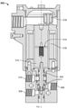
- FIG. 1 illustrates an example emergency system 100 as disclosed herein.
- the emergency system 100 includes a shutdown valve 102, an actuator 104, a solenoid valve (e.g., a solenoid valve 202 of FIG. 2 ), and a valve positioner 106 (e.g., a digital valve controller).
- the actuator 104 includes a first chamber 108, a second chamber 110, and a drive module housing 112.
- the first chamber 108 houses a piston (e.g., a piston 510 of FIG. 5 ) and the second chamber 110 houses a spring (e.g., a spring 514 of FIG. 5 ) that actuates a shaft (e.g., a shaft 502 of FIG.
- the shutdown valve 102 is coupled to the drive module housing 112 of the actuator 104.
- the shutdown valve 102 includes a valve member (e.g., a ball) that transitions the shutdown valve 102 between an open position and a closed position to control an amount of fluid flowing between a first end 114 and a second end 116 of the shutdown valve 102.
- the shaft of the actuator 104 is operatively coupled to the valve member of the shutdown valve 102 to enable the actuator 104 to transition the shutdown valve 102 between the open position and the closed position.
- the actuator 104 causes the shutdown valve 102 to transition to the closed position.
- the shutdown valve 102 closes to prevent the fluid (e.g., potentially hazardous material) from flowing when a dangerous condition is detected to increase and/or improve safety of people, equipment and/or the environment.
- the valve positioner 106 of the example emergency system 100 periodically tests the functionality of the shutdown valve 102 and/or the actuator 104 (e.g., via a partial stroke test) to verify that the shutdown valve 102 is capable of closing.
- the valve positioner 106 periodically conducts a partial stroke test to determine whether the actuator 104 and/or the shutdown valve 102 is damaged and/or otherwise fails to function.
- the emergency system 100 includes a control panel 118 that enables an operator to initiate the valve positioner 106 to test the shutdown valve 102, the actuator 104 and/or the solenoid of the emergency system 100. While the emergency system 100 of the illustrated example includes the shutdown valve 102, the emergency system 100 may alternatively include another type of emergency valve such as a vent valve and/or any other type of valve capable of being actuated via the actuator 104.
- FIG. 2 illustrates the valve positioner 106, the solenoid valve 202, and a portion of the actuator 104 of the example emergency system 100.
- the solenoid valve 202 is de-energized (e.g., power is not supplied to the solenoid valve 202) to cause the solenoid valve 202 to actuate the actuator 104 which, in turn, actuates the shutdown valve 102 ( FIG. 1 ) toward a trip position (e.g., the closed position for the shutdown valve 102).
- the valve positioner 106 of the example emergency system 100 periodically tests the solenoid valve 202 to verify that the solenoid valve 202 will actuate the actuator 104 upon detection of a trip (e.g., hazardous and/or dangerous) condition. For example, the valve positioner 106 conducts a test to determine whether the solenoid valve 202 switches, upon the valve positioner 106 interrupting power provided to the solenoid valve 202, from a first state (e.g., an energized state, a normal state) to a second state (e.g., a de-energized state, an emergency state, a trip state) to actuate the actuator 104.
- a trip e.g., hazardous and/or dangerous
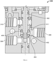
- FIG. 3 is a cross-sectional view of the example solenoid valve 202 of the emergency system 100 ( FIGS. 1-2 ).
- the solenoid valve 202 is a 3/2-way valve in which a stem 302 actuates to define two alternate fluid paths between three ports.
- a first state e.g., an energized state, a normal state
- the stem 302 of the solenoid valve 202 defines a first fluid path between a first valve port 306 and a second valve port 308.
- the stem 302 blocks, seals and/or otherwise prevents fluid to flow through a third valve port 310.
- FIG. 3 is a cross-sectional view of the example solenoid valve 202 of the emergency system 100 ( FIGS. 1-2 ).
- the solenoid valve 202 is a 3/2-way valve in which a stem 302 actuates to define two alternate fluid paths between three ports.
- a first state e.g., an energized state, a normal state
- the stem 302 may be actuated to transition the solenoid valve 202 to a second state (e.g., a de-energized state, an emergency state, a trip state) in which the stem 302 defines a second fluid path 311 of the solenoid valve 202 between the second and third valve ports 308, 310 by blocking, sealing and/or otherwise preventing fluid to flow through the first valve port 306.
- a second state e.g., a de-energized state, an emergency state, a trip state
- the stem 302 is coupled to an armature 312 such that movement of the armature 312 along a pathway 314 causes the stem 302 to traverse between the first state and the second state of the solenoid valve 202.
- the armature 312 is at least partially disposed in the pathway 314 formed by a solenoid coil 316 that produces a magnetic field.
- the armature 312 is composed of magnetic material.
- the magnetic field produced by the solenoid coil 316 urges, moves and/or actuates the armature 312 as the solenoid coil 316 transitions between an energized state and a de-energized state to cause the stem 302 to transition between the first state and the second state of the solenoid valve 202.
- the solenoid coil 316 is de-energized and the armature 312 and the stem 302 are positioned in the second state of the solenoid valve 202.
- the valve positioner 106 interrupts power provided to the solenoid valve 202 for a pulse duration (e.g., a pulse duration 808 of FIGS. 8A-8B ) via wiring that is coupled to the solenoid valve 202 via a terminal block 318.
- a pulse duration e.g., a pulse duration 808 of FIGS. 8A-8B
- the wiring is coupled to the terminal block 318 to communicatively couple the solenoid valve 202 to the valve positioner 106 ( FIGS.
- a controller e.g., a programmable controller, a programmable logic controller, a logic solver, etc.
- a controller e.g., a programmable controller, a programmable logic controller, a logic solver, etc.
- FIG. 4 is an enlarged cross-sectional view of the first, second, and third valve ports 306, 308, 310 and the stem 302 when the solenoid valve 202 is in the second state.
- the stem 302 includes a first seal 402 (e.g., a first o-ring) that engages a body 404 of the solenoid valve 202 adjacent the first valve port 306.
- the first seal 402 forms a seal with the body 404 of the solenoid valve 202 to prevent the first valve port 306 from being in fluid communication with the third valve port 310 and the second valve port 308 when the solenoid valve 202 is in the second state.
- the stem 302 does not block the third valve port 310 or the second valve port 308 when the solenoid valve 202 is in the second state to define the second fluid path 311 of the second state.
- the stem 302 includes a second seal 406 (e.g., a second o-ring) that is to engage the body 404 of the solenoid valve 202 adjacent the third valve port 310 when the solenoid valve 202 is in the first state.
- the second seal 406 forms a seal with the body 404 of the solenoid valve 202 to prevent the third valve port 310 from being in fluid communication with the second valve port 308 or the first valve port 306 in the first state of the solenoid valve 202.
- the stem 302 does not block the second valve port 308 or the first valve port 306 when the solenoid valve 202 is in the first state to define the first fluid path of the first state.
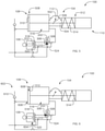
- FIG. 5-6 depict a fluid flow schematic of the example emergency system 100 in which the valve positioner 106 tests the functionality of the solenoid valve 202 independently of testing the functionality of the shutdown valve 102 ( FIG. 1 ) and/or the actuator 104. More specifically, FIG. 5 illustrates the emergency system 100 during testing of the solenoid valve 202 when the solenoid valve 202 is in the first state (e.g., the energized state, the normal state), and FIG. 6 illustrates the emergency system 100 during testing of the solenoid valve 202 when the solenoid valve 202 is in the second state (e.g., the de-energized state, the emergency state, the trip state).
- the first state e.g., the energized state, the normal state
- FIG. 6 illustrates the emergency system 100 during testing of the solenoid valve 202 when the solenoid valve 202 is in the second state (e.g., the de-energized state, the emergency state, the trip state).
- the actuator 104 includes a shaft 502 that is operatively coupled to the valve member of the shutdown valve 102 to actuate the shutdown valve 102 between the open and closed positions.
- the shaft 502 is operatively coupled to a stem 504 of the actuator 104 via a yoke mechanism 506 disposed in the drive module housing 112.
- a first end 508 of the stem 504 extends into the first chamber 108 of the actuator 104 and couples to a piston 510 disposed in the first chamber 108, and a second end 512 of the stem 504 extends into the second chamber 110 and couples to a spring 514 disposed in the second chamber 110.
- the actuator 104 is in a rest position that corresponds to the open position of the shutdown valve 102.
- the spring 514 is preloaded such that the spring 514 is compressed within the second chamber 110.
- pressure within a pressure chamber 516 of the first chamber 108 exerts a force on the piston 510 in a first direction (e.g., to the left in the illustrated example) that is substantially greater than a force (e.g., a preload) exerted by the spring 514 onto the second end 512 of the stem 504 in an opposing direction (e.g., to the right in the illustrated example).
- the actuator 104 remains in the rest position until the force applied by the spring 514 overcomes the force applied by the pressure in the pressure chamber 516.
- the pressure chamber 516 may be vented for a period of time to substantially reduce the pressure within the pressure chamber 516.
- the actuator 104 begins to close the shutdown valve 102 only when the force applied to the piston 510 becomes less than the force applied by the spring 514.
- the valve positioner 106 includes a first pressure port 518, a second pressure port 520, and a third pressure port 522.
- the third pressure port 522 receives supply fluid (e.g., unregulated plant air) that is provided to the first pressure port 518, the first pressure port 518 is in fluid communication with the first valve port 306 of the solenoid valve 202, and the second pressure port 520 is in fluid communication with the second valve port 308 of the solenoid valve 202 and the pressure chamber 516 of the actuator 104 via a sense line 524.
- the third valve port 310 is in fluid communication with a vent.
- the solenoid valve 202 is in the first state in which the third valve port 310 is closed to form the first fluid path between the first valve port 306 and the second valve port 308.
- the pressure chamber 516 of the actuator 104 is in fluid communication with and receives fluid from the first pressure port 518 of the valve positioner 106.
- the fluid provided by the first pressure port 518 causes the pressure chamber 516 to produce a first pressure in the pressure chamber 516 when the solenoid valve 202 is in the first state.
- the first pressure of the pressure chamber 516 applies a first force to the piston 510 that is greater than a preload of the actuator 104 (e.g., provided by the spring 514), thereby enabling the actuator 104 to remain in the rest position when the solenoid valve 202 is in the first state.
- a preload of the actuator 104 e.g., provided by the spring 514
- the valve positioner 106 tests the functionality of the solenoid valve 202 by determining whether the solenoid valve 202 transitions between the first state ( FIG. 5 ) and the second state ( FIG. 6 ) when the valve positioner 106 interrupts power provided to the solenoid valve 202. For example, the valve positioner 106 may detect an error if the stem 302 ( FIGS. 3 and 4 ) does not move and/or moves too slowly to transition the solenoid valve 202 from the first state to the second state upon power interruption from the valve positioner 106. Further, the valve positioner 106 detects whether the solenoid valve 202 transitions from the first state to the second state by determining whether and to what extent the power interruption causes a change in pressure across the solenoid valve 202.
- the valve positioner 106 is able to verify the functionality of the solenoid valve 202 by inducing and measuring a relatively small decrease and/or increase in pressure without affecting the position of the actuator 104 and/or the shutdown valve 102 (e.g., without closing the shutdown valve 102).
- the second pressure port 520 of the valve positioner 106 measures a pressure of the pressure chamber 516 via the sense line 524.
- the valve positioner 106 measures, via the sense line 524, the pressure of the pressure chamber 524 for a predetermined monitoring duration (e.g., a monitoring duration 812 of FIGS. 8A-8B ).
- the valve positioner 106 measures an initial pressure (e.g., an initial pressure 814 of FIG. 8A ) associated with the first state of the solenoid valve 202 at the start of the monitoring time.
- the valve positioner 106 instructs (e.g., by interrupting power provided to) the solenoid valve 202 for a predetermined pulse duration (e.g., the pulse duration 808 of FIGS. 8A-8B ) to transition to the second state.
- a predetermined pulse duration e.g., the pulse duration 808 of FIGS. 8A-8B
- the valve positioner 106 monitors the pressure of the pressure chamber 516 as the solenoid valve 202 is instructed to transition from the first state to the second state.
- FIG. 6 depicts the example emergency system 100 when the solenoid valve 202 is in the second state.
- the first valve port 306 is closed in the second state, thereby forming the second fluid path 311 ( FIGS. 3-4 ) between the second valve port 308 and the third valve port 310 of the solenoid valve 202.
- the solenoid valve 202 enables fluid to be vented from the pressure chamber 516, through the second fluid path 311 of the solenoid valve 202, and to the vent.
- the pressure measured by the second pressure port 520 in the illustrated example decreases over time when the solenoid valve 202 is in the second state relative to when the solenoid valve 202 is in the first state.
- the solenoid valve 202 is instructed to be in the second state (e.g., by interrupting power) from the start time to a pulse end time (e.g., a pulse end time 810 of FIG. 8A ) of the pulse duration. Further, the second pressure port 520 of the valve positioner 106 measures (e.g., continuously monitors via the sense line 524) the pressure of the pressure chamber 516 for the monitoring duration that ends at a monitoring end time (e.g., a monitoring end time 816 of FIG. 8A ). To test the functionality of the solenoid valve 202, the valve positioner 106 identifies a maximum pressure change (e.g., a maximum pressure change 820 of FIGS.
- a maximum pressure change e.g., a maximum pressure change 820 of FIGS.
- the valve positioner 106 compares (e.g., calculates a difference between) the measured maximum pressure change and a minimum trip value (e.g., a minimum trip value 822 of FIGS. 8A-8B ). If the maximum pressure change is less than the minimum trip value, the valve positioner 106 determines that the solenoid valve 202 is in the error and/or abnormal state.
- the solenoid valve 202 is in the error and/or abnormal state if the solenoid valve 202 does not transition and/or transitions too slowly to the second state to safely close the shutdown valve 102 in an emergency.
- the valve positioner 106 may identify that the solenoid valve 202 is in the ready state (e.g., is functioning properly) if the maximum pressure change is greater than the minimum trip value, which indicates that the solenoid valve 202 is able to transition to the second state quickly enough to safely close the shutdown valve 102 in an emergency and/or demand situation.
- the example valve positioner 106 further tests the functionality of the solenoid valve 202 by instructing the solenoid valve 202 to return to the first state upon completion of the pulse duration. For example, the valve positioner 106 continues to monitor the pressure change upon completion of the pulse duration, because the monitoring duration is greater than the pulse duration (e.g., by permitting power to be supplied to the solenoid valve 202). To further determine whether the solenoid valve 202 is in the ready state or the error and/or abnormal state, the valve positioner 106 compares (e.g., calculates a difference between) the pressure change at the monitoring end time (e.g., a pressure change 824 at the monitoring end time 816 of FIG.
- the monitoring end time e.g., a pressure change 824 at the monitoring end time 816 of FIG.
- the valve positioner 106 determines the pressure change at the monitoring end time by comparing the initial pressure to a pressure of the pressure chamber 516 of the actuator 104 at the monitoring end time. If the pressure change at the monitoring end time is greater than a maximum reset value, the valve positioner 106 determines that the solenoid valve is in the error and/or abnormal state. For example, the pressure change at the monitoring end time being greater than a maximum reset value indicates that the solenoid valve 202 fails to reset and/or resets too slowly to the first state upon completion of the pulse signal.
- the valve positioner 106 determines that the solenoid valve 202 is in the ready state if the pressure change at the monitoring end time is less than the maximum reset value and the maximum pressure change is greater than the minimum trip value. By determining whether the solenoid valve 202 is in the ready state based on a comparison of the pressure change relative to the initial pressure, the valve positioner 106 is able to accurately test the functionality of the solenoid valve 202 when there is a varying or fluctuating upstream flow, a varying or fluctuating downstream flow, a delay in communication between the valve positioner 106 and the solenoid valve 202 and/or a mechanical and/or electrical delay in transitioning the stem 302 ( FIGS. 3 and 4 ) of the solenoid valve 202 between the first state and the second state.
- the emergency system 100 incorporates a rebreather system 602 in which the third valve port 310 of the solenoid valve 202, a vent 604 of the valve positioner 106, and a vent 606 of a secondary chamber 608 of the first chamber 108 of the actuator 104 are vented through a check valve 610.
- the vent 606 of the first chamber 108 prevents a vacuum from forming in the secondary chamber 608 as the piston 510 moves within the first chamber 108 (e.g., in a rightward direction in the illustrated example) to further enable movement of the piston 510 when the pressure within the pressure chamber 516 changes.
- the rebreather system 602 enables the secondary chamber 608 to pull in substantially clean air from the vent 604 of the valve positioner 106 and/or the third valve port 310 of the solenoid valve 202. Further, the check valve 610 maintains a pressure (e.g., approximately 1 pound per square inch) within the rebreather system 602 to enable the secondary chamber 608 to draw the vented air from the vent 604 of the valve positioner 106 and/or the third valve port 310 of the solenoid valve 202.
- a pressure e.g., approximately 1 pound per square inch
- valve positioner 106 is capable of testing the functionality of the solenoid valve 202 when the rebreather system 602 is incorporated into the emergency system 100. Additionally or alternatively, the valve positioner 106 is capable of testing the functionality of the solenoid valve 202 when no rebreather system is incorporated into the emergency system 100.
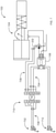
- FIG. 7 depicts an electrical and fluid flow schematic of the emergency system 100 in accordance with the teachings herein when the solenoid valve 202 is in the second state.
- the solenoid valve 202 is communicatively coupled to the valve positioner 106 and a first output source 702 via wiring 704, 706, 708.
- the wiring 704 couples the valve positioner 106 to a terminal block 710
- the wiring 706 couples the terminal block 710 to the solenoid valve 202.
- the wiring 704, 706 enables the valve positioner 106 to interrupt and permit power to be provided to the solenoid valve 202 to test the functionality of the solenoid valve 202.
- the wiring 708 couples the first output source 702 to the terminal block 710 to communicatively couple the first output source 702 to the solenoid valve 202.
- the first output source 702 is an output terminal of a controller (e.g., a programmable controller, a programmable logic controller, a logic solver, etc.) that supplies and/or provides power (e.g., via a +24 VDC signal) to the solenoid valve 202 to open the shutdown valve 102 ( FIG. 1 ) and/or terminates power (e.g., via a 0 VDC signal) to close the shutdown valve 102 upon detection of a hazardous and/or dangerous condition.
- the valve positioner 106 is installed to test the solenoid valve 202 without affecting an ability of the solenoid valve 202 to close the shutdown valve 102 upon detection of a hazardous and/or dangerous condition.
- the valve positioner 106 is communicatively coupled to a second output source 712 that sends an input signal (e.g., a 4-20 mA signal) to the valve positioner 106 to control the valve positioner 106. Further, the output source 712 sends a test signal (e.g., via HART communication protocol, PROFIBUS PA, FOUNDATION Fieldbus, etc.) to start a test (e.g., a partial stroke test) of the solenoid valve 202, the actuator 104 and/or the shutdown valve 102.
- a test signal e.g., via HART communication protocol, PROFIBUS PA, FOUNDATION Fieldbus, etc.
- the valve positioner 106 of the illustrated example tests the functionality of the solenoid valve 202 independently of testing the functionality of the shutdown valve 102 and/or the actuator 104.
- the solenoid valve 202 may be more likely to deteriorate and/or become damaged over time relative to the actuator 104 and/or the shutdown valve 102.
- the valve positioner 106 conducts a test of the solenoid valve 202 more frequently (e.g., monthly) than it may conduct a partial stroke test of the shutdown valve 102 (e.g., quarterly, yearly, etc.). Further, in some examples, the valve positioner 106 is scheduled (e.g., programmed) to conduct a partial stroke test of the shutdown valve 102 upon testing the functionality of the solenoid valve 202.
- valve positioner 106 may be programmed to and/or enable an operator to elect to abort or continue with the scheduled partial stroke test.
- FIG. 8A is a graph 800 depicting an example assessment of a test of the solenoid valve 202 ( FIGS. 2-7 ) conducted via the valve positioner 106 ( FIGS. 1-2 and 5-7 ) in which the solenoid valve 202 is in a ready state.
- a pressure change 802 in the pressure chamber 516 ( FIGS. 5-6 ) of the actuator 104 ( FIGS. 1-2 and 5-6 ) and a pulse signal 804 are plotted in relation to time.
- the pulse signal 804 is sent to transition the solenoid valve 202 from the first state (e.g., an energized state indicated by the value '1' in FIG. 8A ) to the second state (e.g., a de-energized state indicated by the value '0' in FIG. 8A ).
- the pulse signal 804 is sent at the start time 806 and lasts for the pulse duration 808 until the pulse end time 810.
- the valve positioner 106 monitors the pressure across the solenoid valve 202 for the monitoring duration 812. In the illustrated example, the monitoring duration 812 starts at the start time 806 of the pulse duration 808. For example, the valve positioner 106 measures the initial pressure 814 at the start time 806.
- the monitoring duration 812 may start before the start time 806 of the pulse signal 804 such that the initial pressure 814 is measured before the pulse signal 804 is sent. Further, the monitoring duration 812 extends to the monitoring end time 816. The monitoring duration 812 is greater than the pulse duration 808 such that valve positioner 106 continues to monitor the pressure across solenoid valve 202 after the pulse signal 804 has terminated.
- the graph 800 plots the pressure change 802 measured by the valve positioner 106 over time relative to when the valve positioner 106 sends the pulse signal 804 to the solenoid valve 202.
- the valve positioner 106 determines and/or calculates the pressure change 802 by comparing a measurement of the pressure of the pressure chamber 516 at a particular time to the initial pressure 814.
- the valve positioner 106 measures a decrease in pressure upon the valve positioner 106 sending the pulse signal 804 to the solenoid valve 202 and an increase in pressure upon the valve positioner 106 terminating the pulse signal 804.
- the pressure of the pressure chamber 516 begins to decrease approximately at the start time 806 of the pulse signal 804.
- the pressure begins to decrease after the start time 806 due to a delay in communication between the valve positioner 106 and the solenoid valve 202 and/or due to a mechanical and/or electrical delay of the solenoid valve 202 (e.g., a delay in the stem 302 of FIGS. 3 and 4 moving from the first state to the second state).
- the maximum pressure change 820 of the solenoid valve 202 occurs approximately at the pulse end time 810 of the pulse signal 804. In other examples, the maximum pressure change 820 occurs after the pulse signal 804 ends due to a communicative, electrical and/or mechanical delay.
- an operational delay associated with a shutdown valve may result in the shutdown valve venting for a period of time ending slightly beyond the pulse end time 810 of the pulse signal 804.
- the maximum pressure change 820 may occur at a time corresponding to the end of the venting period of the shutdown valve, as opposed to occurring at the pulse end time 810 of the pulse signal 804.
- the maximum pressure change 820 may occur at any point in time during the monitoring duration 812 described above.
- the graph 800 of the illustrated example of FIG. 8A depicts the pressure change 802 of the solenoid valve 202 that is in a ready state.
- the graph 800 of FIG. 8A includes an example minimum trip value 822 (e.g., a minimum trip threshold) and an example maximum reset value 826 (e.g., a maximum reset threshold).
- the minimum trip value 822 corresponds to a minimum pressure change that is to be exceeded at a point in time during the monitoring duration 812 in order for the solenoid valve 202 to be determined to be in a ready state.
- the maximum reset value 826 corresponds to a maximum pressure change that is not to be exceeded at the monitoring end time 816 of the monitoring duration 812 in order for the solenoid valve 202 to be determined to be in a ready state.
- the maximum reset value may be exceeded in instances where the measured pressure of the solenoid valve 202 has not sufficiently returned to the initial pressure 814 by the monitoring end time 816 of the monitoring duration 812.
- the maximum reset value 826 (e.g., the maximum reset threshold) may be set to a value that is approximately twice the value of a nominal pressure change relative to the initial pressure 814.
- the solenoid valve 202 is determined to be in a ready state as the maximum pressure change 820 is greater than the minimum trip value 822 and the pressure change 824 at the monitoring end time 816 is less than the maximum reset value 826.
- FIG. 8B is a graph 828 depicting another example assessment of a test of the solenoid valve 202 ( FIGS. 2-7 ) conducted via the valve positioner 106 ( FIGS. 1-2 and 5-7 ) in which the solenoid valve 202 is in a ready state.
- the pressure change 802 in the pressure chamber 516 ( FIGS. 5-6 ) of the actuator 104 ( FIGS. 1-2 and 5-6 ) and the pulse signal 804 are plotted in relation to time.
- the graph 828 plots the pressure change 802 measured by the valve positioner 106 over time relative to when the valve positioner 106 sends the pulse signal 804 to the solenoid valve 202.
- the pulse duration 808 and the monitoring duration 812 are substantially equal. In other examples, the monitoring duration 812 may be greater than the pulse duration 808.
- the example graph 828 depicts the pressure change 802 of the solenoid valve 202 that is in the ready state.
- the graph 828 of FIG. 8B includes an example minimum trip value 822 (e.g., a minimum trip threshold) and an example maximum trip value 830 (e.g., a maximum trip threshold).
- the minimum trip value 822 corresponds to a minimum pressure change that is to be exceeded at a point in time during the monitoring duration 812 in order for the solenoid valve 202 to be determined to be in a ready state.
- the maximum trip value 830 corresponds to a maximum pressure change that is not to be exceeded at any point in time during the monitoring duration 812 in order for the solenoid valve 202 to be determined to be in a ready state.
- the maximum trip value 830 may be exceeded in instances where too much venting has occurred during the monitoring duration 812.
- the minimum trip value 822 e.g., the minimum trip threshold
- the solenoid valve 202 is determined to be in a ready state as the maximum pressure change 820 measured by the valve positioner 106 is greater than the minimum trip value 822 and is less than the maximum trip value 830. If the maximum pressure change 820 is less than the minimum trip value 822 or greater than the maximum trip value 830, the valve positioner 106 determines that the solenoid valve 202 is in the error and/or abnormal state.
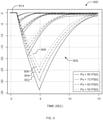
- FIG. 9 is a graph 900 depicting example pressure change measurements taken by the valve positioner 106 ( FIGS. 1-2 and 5-7 ) to assess the functionality of the solenoid valve 202 ( FIGS. 2-7 ).
- the graph 900 includes a first set of lines 902 that corresponds to when the initial pressure 814 ( FIGS. 8A-8B ) is 80 pounds per square inch, a second set of lines 904 that corresponds to when the initial pressure 814 is 70 pounds per square inch, a third set of lines 906 that corresponds to when the initial pressure 814 is 60 pounds per square inch, and a fourth set of lines 908 that corresponds to when the initial pressure 814 is 50 pounds per square inch.
- the initial pressure 814 for each of the sets of lines 902, 904, 906, 908 is normalized to equal '0.'
- the graph 900 illustrates the pressure change 802 for different pulse durations (e.g., 0.25 seconds, 0.5 seconds, 1 second, 2 seconds, 4 seconds).
- the measurements of the graph 900 e.g., the maximum pressure changes
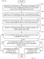
- FIG. 10 is a flowchart representative of an example method 1000 to assess a test of an example solenoid valve via an example valve positioner in accordance with the teachings herein.
- the example method 1000 is described with reference to the flowchart illustrated in FIG. 10 , many other methods of assessing the test of the solenoid valve via the valve positioner may alternatively be used.
- the order of execution of the blocks may be changed, and/or some of the blocks described changed, eliminated, and/or combined.
- the blocks of the example method 1000 may be implemented by executing corresponding instructions (e.g., first instructions, second instructions, third instructions, etc.) via a processor.
- the example method 1000 for assessing a test of a solenoid valve via a valve positioner is discussed in connection with the example emergency system 100 of FIGS. 1-2 and 5-7 , the example graph 800 of FIG. 8A , the example graph 828 of FIG. 8B and/or the example graph 900 of FIG. 9 . Further, because the example method 1000 may refer to the example emergency system 100 of FIGS. 1-2 and 5-7 , the example graph 800 of FIG. 8A , the example graph 828 of FIG. 8B and/or the example graph 900 of FIG. 9 , components identified in FIGS. 1-9 having functions substantially similar or identical to the functions of components described below will not be described in detail again. Instead, the same reference numbers will be used for like structures.
- the example method 1000 disclosed herein starts at block 1002 with a valve positioner (e.g., the valve positioner 106 of FIGS. 1-2 and 5-7 ) monitoring a pressure of a pressure chamber (e.g., the pressure chamber 516 of FIGS. 5-6 ) of an actuator (e.g., the actuator 104 of FIGS. 1-2 and 5-7 ) in fluid communication with a solenoid valve (e.g., the solenoid valve 202 of FIGS. 2-7 ) for a monitoring duration (e.g., the monitoring duration 812 of FIGS. 8A-8B ).
- a valve positioner e.g., the valve positioner 106 of FIGS. 1-2 and 5-7
- monitoring a pressure of a pressure chamber e.g., the pressure chamber 516 of FIGS. 5-6
- an actuator e.g., the actuator 104 of FIGS. 1-2 and 5-7
- a solenoid valve e.g., the solenoid valve 202 of FIGS.
- the valve positioner instructs (e.g., by interrupting power provided to) the solenoid valve to transition from a first state (e.g., an energized state, a normal state) to a second state (e.g., a de-energized state, an emergency state, a trip state) for a duration (e.g., the pulse duration 808 of FIGS. 8A-8B ).
- a first state e.g., an energized state, a normal state
- a second state e.g., a de-energized state, an emergency state, a trip state
- the valve positioner instructs the solenoid valve to return to the first state upon completion and/or termination of the pulse duration.
- the pulse signal induces a pressure change (e.g., the pressure change 802 of FIGS.
- the solenoid valve is in the second state for the pulse duration that starts after the monitoring duration, is less than the monitoring duration, and ends before the monitoring duration.
- the valve positioner identifies a maximum pressure change (e.g., the maximum pressure change 820 of FIGS. 8A-8B ) during the monitoring duration.
- the method 1000 includes determining whether the maximum pressure change is greater than a minimum trip value (e.g., the minimum trip value 822 of FIGS. 8A-8B ). If the maximum pressure change is not greater than the minimum trip value, the valve positioner determines that the solenoid valve is in an error and/or abnormal state and/or has malfunctioned (block 1012).
- the method 1000 includes determining whether a pressure change at an end of the monitoring duration (e.g., the pressure change 824 at the monitoring end time 816 of FIG. 8A ) is less than a maximum reset value (e.g., the maximum reset value 826 of FIG. 8A ).
- Block 1014 may additionally and/or alternatively include determining whether the maximum pressure change is less than a maximum trip value (e.g., the maximum trip value 830 of FIG. 8B ).
- the valve positioner determines that the solenoid valve is in the error and/or abnormal state and/or has malfunctioned (block 1012). If the pressure change at the end of the monitoring duration is less than the maximum reset value (and/or if the maximum pressure change is less than the maximum trip value), the valve positioner determines that the solenoid valve is in a ready state in which the solenoid valve is able to actuate the actuator to close a shutdown valve (e.g., the shutdown valve 102 of FIGS. 1 and 5-7 ) upon detection of a hazardous and/or dangerous condition (block 1016).
- a shutdown valve e.g., the shutdown valve 102 of FIGS. 1 and 5-7
Landscapes
- Engineering & Computer Science (AREA)
- General Engineering & Computer Science (AREA)
- Mechanical Engineering (AREA)
- Physics & Mathematics (AREA)
- Fluid Mechanics (AREA)
- Testing Of Devices, Machine Parts, Or Other Structures Thereof (AREA)
- Fluid-Driven Valves (AREA)
- Indication Of The Valve Opening Or Closing Status (AREA)
- Magnetically Actuated Valves (AREA)
Claims (18)
- Appareil pour tester une électrovanne, l'appareil comprenant :un actionneur (104) configuré pour fermer une vanne de secours (102) ;une électrovanne (202) configurée pour permettre à l'actionneur (104) de fermer la vanne de secours (102) ; etun positionneur de vanne (106) couplé de manière fluidique et en communication avec l'électrovanne (202), le positionneur de vanne (106) comprenant un processeur ; le positionneur de vanne (106) étant configuré pour :ordonner à l'électrovanne (202) pour une durée d'impulsion (808) de passer d'un premier état à un second état, la durée d'impulsion (808) s'étendant d'un temps de début (806) à un temps de fin d'impulsion (810), et ordonner à l'électrovanne (106) de passer du second état au premier état à la fin de la durée d'impulsion (808) ;surveiller un changement de pression d'une chambre de pression (516) de l'actionneur (140) en communication fluidique avec l'électrovanne (202) par rapport à une pression initiale (814) pendant une durée de surveillance (812) qui s'étend du temps de début à un temps de fin de surveillance (816) ;caractérisé en ce que le positionneur de vanne (106) est en outre configuré pour :identifier un changement de pression maximum (820) pendant la durée de surveillance (812) ; etdéterminer un état prêt de l'électrovanne (202) lorsque le changement de pression maximum est supérieur à une valeur de déclenchement minimum (822) et lorsque le changement de pression au temps de fin de surveillance est inférieur à une valeur de réinitialisation maximum (826).
- Appareil selon la revendication 1, dans lequel le positionneur de vanne (106) est configuré pour déterminer un état d'erreur de l'électrovanne (202) lorsque le changement de pression maximum (820) est inférieur à la valeur de déclenchement minimum (822) et/ou lorsque le changement de pression au temps de fin de surveillance (816) est supérieur à la valeur de réinitialisation maximum (826).
- Appareil selon l'une quelconque des revendications précédentes, dans lequel la durée de surveillance (812) du positionneur de vanne (106) est supérieure à la durée d'impulsion (808).
- Appareil selon l'une quelconque des revendications précédentes, dans lequel le positionneur de vanne (106) est configuré pour déterminer le changement de pression maximum (820) en comparant la pression initiale de la chambre de pression (516) de l'actionneur (104) et une pression minimum mesurée de la chambre de pression (516) par le positionneur de vanne (106) et pour déterminer le changement de pression à l'instant de fin de surveillance (816) en comparant la pression initiale (814) et une pression de la chambre de pression (516) mesurée au temps de fin de surveillance (816) par le positionneur de vanne (106).
- Appareil selon l'une quelconque des revendications précédentes, dans lequel le positionneur de vanne (106) est en outre configuré pour déterminer l'état prêt de l'électrovanne (202) lorsque le changement de pression maximum (820) est supérieur à la valeur de déclenchement minimum (822) et inférieur à une valeur de déclenchement maximum (830), la valeur de déclenchement minimum (822) étant approximativement la moitié de la valeur de déclenchement maximum (830).
- Appareil selon l'une quelconque des revendications précédentes, dans lequel la valeur de réinitialisation maximum (826) est approximativement le double d'un changement de pression nominale par rapport à la pression initiale (814).
- Appareil selon l'une quelconque des revendications précédentes, dans lequel le positionneur de vanne (106) est en outre configuré pour tester l'électrovanne (202) sans amener l'électrovanne (202) à actionner la vanne de secours (102).
- Appareil selon l'une quelconque des revendications précédentes, dans lequel le positionneur de vanne (106) est en outre configuré pour tester l'électrovanne (202) indépendamment du test de la vanne de secours (102).
- Procédé pour tester une électrovanne, le procédé comprenant les étapes consistant à :ordonner, en exécutant des premières instructions via un processeur, à une électrovanne (202) pendant une durée d'impulsion (808) de passer d'un premier état à un second état, l'électrovanne (202) étant configurée pour permettre à un actionneur (104) de fermer une vanne de secours (102), la durée d'impulsion (808) s'étendant d'un temps de début (806) à un temps de fin d'impulsion (810) ;ordonner, en exécutant des deuxièmes instructions via le processeur, à l'électrovanne (202) de passer du second état au premier état au temps de fin d'impulsion (810) ; etsurveiller, en exécutant des troisièmes instructions via le processeur, un changement de pression d'une chambre de pression (516) de l'actionneur (104) en communication fluidique avec l'électrovanne (202) par rapport à une pression initiale (814) pendant une durée de surveillance (812) qui s'étend du temps de début à un temps de fin de surveillance (816) ;caractérisé en ce que le procédé comprend en outre les étapes consistant à :identifier, en exécutant des quatrièmes instructions via le processeur, un changement de pression maximum (820) pendant la durée de surveillance (812) ; etdéterminer, en exécutant des cinquièmes instructions via un processeur, un état prêt de l'électrovanne (202) lorsque le changement de pression maximum (820) est supérieur à une valeur de déclenchement minimum (822) et que le changement de pression au temps de fin de surveillance (816) est inférieur à une valeur de réinitialisation maximum (826).
- Procédé selon la revendication 9, comprenant en outre la détermination d'un état d'erreur de l'électrovanne (202) lorsque le changement de pression maximum (820) est inférieur à la valeur de déclenchement minimum (822) et/ou le changement de pression au temps de fin de surveillance (816) est supérieur à la valeur de réinitialisation maximum (826).
- Procédé selon l'une quelconque des revendications précédentes, dans lequel l'identification que le changement de pression maximum (820) est inférieur à la valeur de déclenchement minimum (822) indique que l'électrovanne (202) est lente pour amener l'actionneur (104) à fermer la vanne de secours (102).
- Procédé selon l'une quelconque des revendications précédentes, dans lequel l'identification que le changement de pression au temps de fin de surveillance (816) est supérieur à la valeur de réinitialisation maximum (826) indique que l'électrovanne (202) est lente pour amener l'actionneur (104) à rouvrir la vanne de secours (102) lors d'une fermeture.
- Procédé selon l'une quelconque des revendications précédentes, dans lequel la durée de surveillance (812) est supérieure à la durée d'impulsion (808).
- Procédé selon l'une quelconque des revendications précédentes, comprenant en outre une détermination du changement de pression maximum en calculant une différence entre la pression initiale (814) aux bornes de la chambre de pression (516) et une pression minimum de la chambre de pression (516) pendant la durée de surveillance (812).
- Procédé selon l'une quelconque des revendications précédentes, comprenant en outre une détermination du changement de pression au temps de fin de surveillance (816) en calculant une différence entre la pression initiale de la chambre de pression (516) et une pression de la chambre de pression (516) au temps de fin de surveillance (816).
- Procédé selon l'une quelconque des revendications précédentes, comprenant en outre la détermination de l'état prêt de l'électrovanne (202) lorsque le changement de pression maximum (820) est supérieur à la valeur de déclenchement minimum (822) et inférieur à une valeur de déclenchement maximum (830), la valeur de déclenchement minimum (822) étant approximativement la moitié de la valeur de déclenchement maximum (830).
- Procédé selon l'une quelconque des revendications précédentes, dans lequel la valeur de réinitialisation maximum (826) est approximativement le double d'un changement de pression nominale par rapport à la pression initiale (814).
- Procédé selon l'une quelconque des revendications précédentes, dans lequel la détermination de l'état prêt de l'électrovanne (202) en fonction du changement de pression de la chambre de pression (516) par rapport à la pression initiale (814) permet à l'électrovanne (202) d'être testée lorsqu'il y a au moins l'un d'un écoulement en amont variable, d'un écoulement en aval variable, d'un retard de communication entre un positionneur de vanne (106) et l'électrovanne (202), ou d'un retard mécanique dans le passage de l'électrovanne (202) entre le premier état et le second état.
Applications Claiming Priority (2)
| Application Number | Priority Date | Filing Date | Title |
|---|---|---|---|
| US15/298,726 US10234058B2 (en) | 2016-10-20 | 2016-10-20 | Methods and apparatus of assessing a test of a solenoid valve via a positioner |
| PCT/US2017/056263 WO2018075321A1 (fr) | 2016-10-20 | 2017-10-12 | Procédés et appareils d'évaluation d'un test d'une électrovanne par l'intermédiaire d'un positionneur |
Publications (2)
| Publication Number | Publication Date |
|---|---|
| EP3529501A1 EP3529501A1 (fr) | 2019-08-28 |
| EP3529501B1 true EP3529501B1 (fr) | 2022-02-23 |
Family
ID=60202434
Family Applications (1)
| Application Number | Title | Priority Date | Filing Date |
|---|---|---|---|
| EP17793758.8A Active EP3529501B1 (fr) | 2016-10-20 | 2017-10-12 | Procédés et appareils d'évaluation d'un test d'une électrovanne par l'intermédiaire d'un positionneur |
Country Status (6)
| Country | Link |
|---|---|
| US (1) | US10234058B2 (fr) |
| EP (1) | EP3529501B1 (fr) |
| CN (2) | CN208252921U (fr) |
| CA (1) | CA3041573A1 (fr) |
| RU (1) | RU2751050C2 (fr) |
| WO (1) | WO2018075321A1 (fr) |
Families Citing this family (5)
| Publication number | Priority date | Publication date | Assignee | Title |
|---|---|---|---|---|
| US10234058B2 (en) * | 2016-10-20 | 2019-03-19 | Fisher Controls International Llc | Methods and apparatus of assessing a test of a solenoid valve via a positioner |
| US10240687B2 (en) | 2016-10-20 | 2019-03-26 | Fisher Controls International Llc | Methods and apparatus of testing a solenoid valve of an emergency valve via a positioner |
| DE102019135327B3 (de) * | 2019-12-19 | 2021-01-07 | Samson Aktiengesellschaft | Verfahren zum Prüfen der Funktionsfähigkeit eines Magnetventils zum Auslösen eines Sicherheitsventils |
| DE102020114679B4 (de) | 2020-06-02 | 2022-06-02 | Samson Aktiengesellschaft | Prüfen der Funktionsfähigkeit eines Sicherheitsventils für einen Sicherheitsfall |
| JP2023037586A (ja) * | 2021-09-03 | 2023-03-15 | レヴィトロニクス ゲーエムベーハー | ピンチバルブシステム |
Family Cites Families (53)
| Publication number | Priority date | Publication date | Assignee | Title |
|---|---|---|---|---|
| US3829842A (en) * | 1973-02-22 | 1974-08-13 | Terry Controls Corp | Automatic self-testing programmable industrial controller |
| US4428223A (en) * | 1978-05-16 | 1984-01-31 | Furmanite International Limited | Apparatus for periodically testing the operation of safety valves |
| GB8321751D0 (en) * | 1983-08-12 | 1983-09-14 | Greenwood Moore Ltd | Valve testing |
| US4556956A (en) * | 1983-09-16 | 1985-12-03 | General Electric Company | Adjustable gain controller for valve position control loop and method for reducing jitter |
| US5197328A (en) * | 1988-08-25 | 1993-03-30 | Fisher Controls International, Inc. | Diagnostic apparatus and method for fluid control valves |
| US5329956A (en) | 1993-05-28 | 1994-07-19 | Combustion Engineering, Inc. | Pneumatic operated valve stroke timing |
| US5549137A (en) * | 1993-08-25 | 1996-08-27 | Rosemount Inc. | Valve positioner with pressure feedback, dynamic correction and diagnostics |
| DE19643297C1 (de) * | 1996-10-21 | 1998-03-12 | Samson Ag | Verfahren und Vorrichtung zur Überwachung von Stellgeräten |
| CN1095767C (zh) * | 1996-11-29 | 2002-12-11 | 罗伊·麦克埃里斯特 | 一种气囊流体供应导管装置和气囊系统 |
| FI116587B (fi) * | 1997-10-17 | 2005-12-30 | Metso Automation Oy | Menetelmä ja laitteisto turvalaitteen toimintakunnon todentamiseksi |
| US6186167B1 (en) * | 1999-03-04 | 2001-02-13 | Fisher Controls International Inc. | Emergency shutdown test system |
| GB2372087A (en) | 2001-02-07 | 2002-08-14 | Drallim Ltd | Testing an emergency valve |
| US6435022B1 (en) | 2001-02-09 | 2002-08-20 | Tareq Nasser Albuaijan | Partial stroke testing system |
| WO2002082199A1 (fr) * | 2001-04-05 | 2002-10-17 | Fisher Controls International Llc | Systeme d'essai de dispositif de commande avec actionnement de commutateur a distance |
| US7621293B2 (en) | 2001-04-05 | 2009-11-24 | Fisher Controls International Llc | Versatile emergency shutdown device controller implementing a pneumatic test for a system instrument device |
| US6678584B2 (en) | 2002-05-03 | 2004-01-13 | Fisher Controls International Llc | Method and apparatus for performing diagnostics in a control loop of a control valve |
| GB2404239A (en) | 2003-07-25 | 2005-01-26 | Ics Triplex Technology Ltd | Partial stroke valve test apparatus to test emergency shutdown valves |
| US7464721B2 (en) | 2004-06-14 | 2008-12-16 | Rosemount Inc. | Process equipment validation |
| US7556238B2 (en) | 2005-07-20 | 2009-07-07 | Fisher Controls International Llc | Emergency shutdown system |
| US7661439B2 (en) * | 2006-02-07 | 2010-02-16 | Dresser, Inc. | Safety override circuit for pneumatic positioner and method of use thereof |
| US7609056B2 (en) | 2006-09-11 | 2009-10-27 | Fisher Controls International Llc | Apparatus to determine the position of an actuator |
| DE202006020516U1 (de) * | 2006-12-21 | 2008-10-16 | Abb Ag | Regeleinrichtung für einen druckmittelbetriebenen Stellantrieb |
| US8725434B2 (en) | 2006-12-29 | 2014-05-13 | Saudi Arabian Oil Company | Wellhead hips with automatic testing and self-diagnostics |
| DE102007022762B4 (de) | 2007-05-15 | 2012-09-06 | Siemens Ag | Verfahren zur Überprüfung der Funktionsfähigkeit eines Stellgerätes |
| DE102008007651B3 (de) * | 2008-02-06 | 2009-09-24 | Samson Aktiengesellschaft | Stellungsregler für doppeltwirkenden, pneumatischen Stellantrieb, doppeltwirkender, pneumatischer Stellantrieb und Verfahren zum Betreiben des doppeltwirkenden, pneumatischen Stellantriebs |
| US20120042721A1 (en) | 2008-02-28 | 2012-02-23 | Tareq Nasser Al-Buaijan | Partial stroke testing system coupled with fuel control valve |
| US8074512B2 (en) | 2008-02-28 | 2011-12-13 | Tareq Nasser Al-Buaijan | Partial stroke testing system coupled with fuel control valve |
| WO2010010315A1 (fr) * | 2008-07-25 | 2010-01-28 | Norgren Limited | Appareil d'essai de soupape automatique |
| US9874870B2 (en) * | 2009-08-26 | 2018-01-23 | Fisher-Rosemount Systems, Inc. | Methods and apparatus to manage testing of a process control system |
| US8479734B2 (en) * | 2009-11-10 | 2013-07-09 | John Steven Wood | Overpressure protection system and method for a hyperbaric chamber |
| US8996328B2 (en) | 2009-12-29 | 2015-03-31 | Fisher Controls International Llc | Methods, apparatus and articles of manufacture to test safety instrumented system solenoids |
| DE102010015647B4 (de) | 2010-04-20 | 2011-12-29 | Samson Aktiengesellschaft | Verfahren zum Bestimmen einer Betriebsposition eines Auf/Zu-Ventils und Feldgerät |
| RU98505U1 (ru) * | 2010-06-25 | 2010-10-20 | Открытое акционерное общество Научно-производственное объединение "Наука" (ОАО НПО "Наука") | Устройство для испытаний предохранительных клапанов |
| CN102384303B (zh) * | 2010-08-31 | 2014-11-26 | 金子产业株式会社 | 截止阀控制系统 |
| RU102238U1 (ru) * | 2010-10-26 | 2011-02-20 | Открытое акционерное общество Научно-производственное объединение "Наука" (ОАО НПО "Наука") | Устройство для проверки герметичности электромагнитных клапанов при испытаниях на линейные перегрузки |
| CN202182232U (zh) * | 2011-06-13 | 2012-04-04 | 费希尔控制国际公司 | 用于阀组件的致动器以及用于电动机和阀组件的控制系统 |
| US8905371B2 (en) * | 2011-06-30 | 2014-12-09 | General Equipment And Manufacturing Company, Inc. | Valve signature diagnosis and leak test device |
| JP5843558B2 (ja) * | 2011-10-14 | 2016-01-13 | アズビル株式会社 | ポジショナ |
| US20130118246A1 (en) | 2011-11-14 | 2013-05-16 | Tareq Nasser Al-Buaijan | Shut-off valve testing system |
| US9255649B2 (en) * | 2012-08-07 | 2016-02-09 | Fisher Controls International, Llc | Apparatus for fluid control device leak detection |
| US20140358303A1 (en) | 2013-06-03 | 2014-12-04 | Tescom Corporation | Method and Apparatus for Stabilizing Pressure in an Intelligent Regulator Assembly |
| US9752599B2 (en) | 2014-05-07 | 2017-09-05 | Fisher Controls International Llc | Methods and apparatus to partial stroke test valves using pressure control |
| WO2016057442A2 (fr) | 2014-10-06 | 2016-04-14 | Fisher Controls International Llc | Transition de coupure pour dispositifs de positionnement de vanne de commande |
| CN206075161U (zh) | 2015-03-19 | 2017-04-05 | 费希尔控制产品国际有限公司 | 用于校准定位器的装置、过程控制系统和计算机设备 |
| US9611873B2 (en) | 2015-03-19 | 2017-04-04 | Fisher Controls International Llc | Pressure control for partial stroke tests |
| DE102015007147A1 (de) * | 2015-06-03 | 2016-12-08 | Samson Aktiengesellschaft | Elektro-pneumatischer Aktor |
| US9551434B1 (en) | 2015-07-27 | 2017-01-24 | Fei-Che Hung | Method of inspecting switching time with fluid control valve |
| US10480681B2 (en) | 2015-12-23 | 2019-11-19 | Fisher Controls International Llc | Partial stroke tests for shutdown valves |
| US9732878B2 (en) | 2016-01-11 | 2017-08-15 | Hassan Abdullah Ahmad Alkandari | Partial stroke testing system for emergency shut-off valves |
| US20170350421A1 (en) | 2016-06-06 | 2017-12-07 | Cowan Dynamics Inc. | Manifold for a directional control valve for a valve actuator |
| US10240687B2 (en) | 2016-10-20 | 2019-03-26 | Fisher Controls International Llc | Methods and apparatus of testing a solenoid valve of an emergency valve via a positioner |
| US10234058B2 (en) * | 2016-10-20 | 2019-03-19 | Fisher Controls International Llc | Methods and apparatus of assessing a test of a solenoid valve via a positioner |
| US10041610B2 (en) | 2016-10-20 | 2018-08-07 | Fisher Controls International Llc | Methods and apparatus of stabilizing a valve positioner when testing a solenoid valve |
-
2016
- 2016-10-20 US US15/298,726 patent/US10234058B2/en active Active
-
2017
- 2017-10-12 WO PCT/US2017/056263 patent/WO2018075321A1/fr unknown
- 2017-10-12 CA CA3041573A patent/CA3041573A1/fr active Pending
- 2017-10-12 EP EP17793758.8A patent/EP3529501B1/fr active Active
- 2017-10-12 RU RU2019114095A patent/RU2751050C2/ru active
- 2017-10-18 CN CN201721350167.6U patent/CN208252921U/zh not_active Withdrawn - After Issue
- 2017-10-18 CN CN201710972809.4A patent/CN107965610B/zh active Active
Also Published As
| Publication number | Publication date |
|---|---|
| CN107965610A (zh) | 2018-04-27 |
| RU2751050C2 (ru) | 2021-07-07 |
| WO2018075321A1 (fr) | 2018-04-26 |
| CN107965610B (zh) | 2021-09-07 |
| CN208252921U (zh) | 2018-12-18 |
| EP3529501A1 (fr) | 2019-08-28 |
| CA3041573A1 (fr) | 2018-04-26 |
| US20180112797A1 (en) | 2018-04-26 |
| RU2019114095A3 (fr) | 2021-02-02 |
| RU2019114095A (ru) | 2020-11-20 |
| US10234058B2 (en) | 2019-03-19 |
Similar Documents
| Publication | Publication Date | Title |
|---|---|---|
| EP3529500B1 (fr) | Procédés et appareil d'essai d'une électrovanne d'une soupape d'urgence par l'intermédiaire d'un positionneur | |
| EP3529501B1 (fr) | Procédés et appareils d'évaluation d'un test d'une électrovanne par l'intermédiaire d'un positionneur | |
| EP3529499B1 (fr) | Procédés et appareil de stabilisation d'un dispositif de positionnement de vanne lors du test d'une électrovanne | |
| US11719360B2 (en) | Partial stroke tests for shutdown valves | |
| US7539560B2 (en) | Control valve and positioner diagnostics | |
| EP3347776B2 (fr) | Configuration d'un contrôleur de soupape | |
| US20230304603A1 (en) | Testing the operability of a safety valve for a safety case |
Legal Events
| Date | Code | Title | Description |
|---|---|---|---|
| STAA | Information on the status of an ep patent application or granted ep patent |
Free format text: STATUS: UNKNOWN |
|
| STAA | Information on the status of an ep patent application or granted ep patent |
Free format text: STATUS: THE INTERNATIONAL PUBLICATION HAS BEEN MADE |
|
| PUAI | Public reference made under article 153(3) epc to a published international application that has entered the european phase |
Free format text: ORIGINAL CODE: 0009012 |
|
| STAA | Information on the status of an ep patent application or granted ep patent |
Free format text: STATUS: REQUEST FOR EXAMINATION WAS MADE |
|
| 17P | Request for examination filed |
Effective date: 20190506 |
|
| AK | Designated contracting states |
Kind code of ref document: A1 Designated state(s): AL AT BE BG CH CY CZ DE DK EE ES FI FR GB GR HR HU IE IS IT LI LT LU LV MC MK MT NL NO PL PT RO RS SE SI SK SM TR |
|
| AX | Request for extension of the european patent |
Extension state: BA ME |
|
| DAV | Request for validation of the european patent (deleted) | ||
| DAX | Request for extension of the european patent (deleted) | ||
| GRAP | Despatch of communication of intention to grant a patent |
Free format text: ORIGINAL CODE: EPIDOSNIGR1 |
|
| STAA | Information on the status of an ep patent application or granted ep patent |
Free format text: STATUS: GRANT OF PATENT IS INTENDED |
|
| INTG | Intention to grant announced |
Effective date: 20210908 |
|
| GRAS | Grant fee paid |
Free format text: ORIGINAL CODE: EPIDOSNIGR3 |
|
| GRAA | (expected) grant |
Free format text: ORIGINAL CODE: 0009210 |
|
| STAA | Information on the status of an ep patent application or granted ep patent |
Free format text: STATUS: THE PATENT HAS BEEN GRANTED |
|
| AK | Designated contracting states |
Kind code of ref document: B1 Designated state(s): AL AT BE BG CH CY CZ DE DK EE ES FI FR GB GR HR HU IE IS IT LI LT LU LV MC MK MT NL NO PL PT RO RS SE SI SK SM TR |
|
| REG | Reference to a national code |
Ref country code: GB Ref legal event code: FG4D |
|
| REG | Reference to a national code |
Ref country code: CH Ref legal event code: EP |
|
| REG | Reference to a national code |
Ref country code: AT Ref legal event code: REF Ref document number: 1470677 Country of ref document: AT Kind code of ref document: T Effective date: 20220315 |
|
| REG | Reference to a national code |
Ref country code: IE Ref legal event code: FG4D |
|
| REG | Reference to a national code |
Ref country code: DE Ref legal event code: R096 Ref document number: 602017053761 Country of ref document: DE |
|
| REG | Reference to a national code |
Ref country code: LT Ref legal event code: MG9D |
|
| REG | Reference to a national code |
Ref country code: NL Ref legal event code: MP Effective date: 20220223 |
|
| REG | Reference to a national code |
Ref country code: AT Ref legal event code: MK05 Ref document number: 1470677 Country of ref document: AT Kind code of ref document: T Effective date: 20220223 |
|
| PG25 | Lapsed in a contracting state [announced via postgrant information from national office to epo] |
Ref country code: SE Free format text: LAPSE BECAUSE OF FAILURE TO SUBMIT A TRANSLATION OF THE DESCRIPTION OR TO PAY THE FEE WITHIN THE PRESCRIBED TIME-LIMIT Effective date: 20220223 Ref country code: RS Free format text: LAPSE BECAUSE OF FAILURE TO SUBMIT A TRANSLATION OF THE DESCRIPTION OR TO PAY THE FEE WITHIN THE PRESCRIBED TIME-LIMIT Effective date: 20220223 Ref country code: PT Free format text: LAPSE BECAUSE OF FAILURE TO SUBMIT A TRANSLATION OF THE DESCRIPTION OR TO PAY THE FEE WITHIN THE PRESCRIBED TIME-LIMIT Effective date: 20220623 Ref country code: NO Free format text: LAPSE BECAUSE OF FAILURE TO SUBMIT A TRANSLATION OF THE DESCRIPTION OR TO PAY THE FEE WITHIN THE PRESCRIBED TIME-LIMIT Effective date: 20220523 Ref country code: NL Free format text: LAPSE BECAUSE OF FAILURE TO SUBMIT A TRANSLATION OF THE DESCRIPTION OR TO PAY THE FEE WITHIN THE PRESCRIBED TIME-LIMIT Effective date: 20220223 Ref country code: LT Free format text: LAPSE BECAUSE OF FAILURE TO SUBMIT A TRANSLATION OF THE DESCRIPTION OR TO PAY THE FEE WITHIN THE PRESCRIBED TIME-LIMIT Effective date: 20220223 Ref country code: HR Free format text: LAPSE BECAUSE OF FAILURE TO SUBMIT A TRANSLATION OF THE DESCRIPTION OR TO PAY THE FEE WITHIN THE PRESCRIBED TIME-LIMIT Effective date: 20220223 Ref country code: ES Free format text: LAPSE BECAUSE OF FAILURE TO SUBMIT A TRANSLATION OF THE DESCRIPTION OR TO PAY THE FEE WITHIN THE PRESCRIBED TIME-LIMIT Effective date: 20220223 Ref country code: BG Free format text: LAPSE BECAUSE OF FAILURE TO SUBMIT A TRANSLATION OF THE DESCRIPTION OR TO PAY THE FEE WITHIN THE PRESCRIBED TIME-LIMIT Effective date: 20220523 |
|
| PG25 | Lapsed in a contracting state [announced via postgrant information from national office to epo] |
Ref country code: PL Free format text: LAPSE BECAUSE OF FAILURE TO SUBMIT A TRANSLATION OF THE DESCRIPTION OR TO PAY THE FEE WITHIN THE PRESCRIBED TIME-LIMIT Effective date: 20220223 Ref country code: LV Free format text: LAPSE BECAUSE OF FAILURE TO SUBMIT A TRANSLATION OF THE DESCRIPTION OR TO PAY THE FEE WITHIN THE PRESCRIBED TIME-LIMIT Effective date: 20220223 Ref country code: GR Free format text: LAPSE BECAUSE OF FAILURE TO SUBMIT A TRANSLATION OF THE DESCRIPTION OR TO PAY THE FEE WITHIN THE PRESCRIBED TIME-LIMIT Effective date: 20220524 Ref country code: FI Free format text: LAPSE BECAUSE OF FAILURE TO SUBMIT A TRANSLATION OF THE DESCRIPTION OR TO PAY THE FEE WITHIN THE PRESCRIBED TIME-LIMIT Effective date: 20220223 Ref country code: AT Free format text: LAPSE BECAUSE OF FAILURE TO SUBMIT A TRANSLATION OF THE DESCRIPTION OR TO PAY THE FEE WITHIN THE PRESCRIBED TIME-LIMIT Effective date: 20220223 |
|
| PG25 | Lapsed in a contracting state [announced via postgrant information from national office to epo] |
Ref country code: IS Free format text: LAPSE BECAUSE OF FAILURE TO SUBMIT A TRANSLATION OF THE DESCRIPTION OR TO PAY THE FEE WITHIN THE PRESCRIBED TIME-LIMIT Effective date: 20220623 |
|
| PG25 | Lapsed in a contracting state [announced via postgrant information from national office to epo] |
Ref country code: SM Free format text: LAPSE BECAUSE OF FAILURE TO SUBMIT A TRANSLATION OF THE DESCRIPTION OR TO PAY THE FEE WITHIN THE PRESCRIBED TIME-LIMIT Effective date: 20220223 Ref country code: SK Free format text: LAPSE BECAUSE OF FAILURE TO SUBMIT A TRANSLATION OF THE DESCRIPTION OR TO PAY THE FEE WITHIN THE PRESCRIBED TIME-LIMIT Effective date: 20220223 Ref country code: RO Free format text: LAPSE BECAUSE OF FAILURE TO SUBMIT A TRANSLATION OF THE DESCRIPTION OR TO PAY THE FEE WITHIN THE PRESCRIBED TIME-LIMIT Effective date: 20220223 Ref country code: EE Free format text: LAPSE BECAUSE OF FAILURE TO SUBMIT A TRANSLATION OF THE DESCRIPTION OR TO PAY THE FEE WITHIN THE PRESCRIBED TIME-LIMIT Effective date: 20220223 Ref country code: DK Free format text: LAPSE BECAUSE OF FAILURE TO SUBMIT A TRANSLATION OF THE DESCRIPTION OR TO PAY THE FEE WITHIN THE PRESCRIBED TIME-LIMIT Effective date: 20220223 Ref country code: CZ Free format text: LAPSE BECAUSE OF FAILURE TO SUBMIT A TRANSLATION OF THE DESCRIPTION OR TO PAY THE FEE WITHIN THE PRESCRIBED TIME-LIMIT Effective date: 20220223 |
|
| REG | Reference to a national code |
Ref country code: DE Ref legal event code: R097 Ref document number: 602017053761 Country of ref document: DE |
|
| PG25 | Lapsed in a contracting state [announced via postgrant information from national office to epo] |
Ref country code: AL Free format text: LAPSE BECAUSE OF FAILURE TO SUBMIT A TRANSLATION OF THE DESCRIPTION OR TO PAY THE FEE WITHIN THE PRESCRIBED TIME-LIMIT Effective date: 20220223 |
|
| PLBE | No opposition filed within time limit |
Free format text: ORIGINAL CODE: 0009261 |
|
| STAA | Information on the status of an ep patent application or granted ep patent |
Free format text: STATUS: NO OPPOSITION FILED WITHIN TIME LIMIT |
|
| 26N | No opposition filed |
Effective date: 20221124 |
|
| PG25 | Lapsed in a contracting state [announced via postgrant information from national office to epo] |
Ref country code: SI Free format text: LAPSE BECAUSE OF FAILURE TO SUBMIT A TRANSLATION OF THE DESCRIPTION OR TO PAY THE FEE WITHIN THE PRESCRIBED TIME-LIMIT Effective date: 20220223 |
|
| REG | Reference to a national code |
Ref country code: DE Ref legal event code: R119 Ref document number: 602017053761 Country of ref document: DE |
|
| PG25 | Lapsed in a contracting state [announced via postgrant information from national office to epo] |
Ref country code: MC Free format text: LAPSE BECAUSE OF FAILURE TO SUBMIT A TRANSLATION OF THE DESCRIPTION OR TO PAY THE FEE WITHIN THE PRESCRIBED TIME-LIMIT Effective date: 20220223 |
|
| REG | Reference to a national code |
Ref country code: CH Ref legal event code: PL |
|
| REG | Reference to a national code |
Ref country code: BE Ref legal event code: MM Effective date: 20221031 |
|
| PG25 | Lapsed in a contracting state [announced via postgrant information from national office to epo] |
Ref country code: LU Free format text: LAPSE BECAUSE OF NON-PAYMENT OF DUE FEES Effective date: 20221012 |
|
| P01 | Opt-out of the competence of the unified patent court (upc) registered |
Effective date: 20230526 |
|
| PG25 | Lapsed in a contracting state [announced via postgrant information from national office to epo] |
Ref country code: LI Free format text: LAPSE BECAUSE OF NON-PAYMENT OF DUE FEES Effective date: 20221031 Ref country code: IT Free format text: LAPSE BECAUSE OF FAILURE TO SUBMIT A TRANSLATION OF THE DESCRIPTION OR TO PAY THE FEE WITHIN THE PRESCRIBED TIME-LIMIT Effective date: 20220223 Ref country code: DE Free format text: LAPSE BECAUSE OF NON-PAYMENT OF DUE FEES Effective date: 20230503 Ref country code: CH Free format text: LAPSE BECAUSE OF NON-PAYMENT OF DUE FEES Effective date: 20221031 |
|
| PG25 | Lapsed in a contracting state [announced via postgrant information from national office to epo] |
Ref country code: BE Free format text: LAPSE BECAUSE OF NON-PAYMENT OF DUE FEES Effective date: 20221031 |
|
| PG25 | Lapsed in a contracting state [announced via postgrant information from national office to epo] |
Ref country code: IE Free format text: LAPSE BECAUSE OF NON-PAYMENT OF DUE FEES Effective date: 20221012 |
|
| PGFP | Annual fee paid to national office [announced via postgrant information from national office to epo] |
Ref country code: GB Payment date: 20230920 Year of fee payment: 7 |
|
| PGFP | Annual fee paid to national office [announced via postgrant information from national office to epo] |
Ref country code: FR Payment date: 20230920 Year of fee payment: 7 |
|
| PG25 | Lapsed in a contracting state [announced via postgrant information from national office to epo] |
Ref country code: HU Free format text: LAPSE BECAUSE OF FAILURE TO SUBMIT A TRANSLATION OF THE DESCRIPTION OR TO PAY THE FEE WITHIN THE PRESCRIBED TIME-LIMIT; INVALID AB INITIO Effective date: 20171012 |
|
| PG25 | Lapsed in a contracting state [announced via postgrant information from national office to epo] |
Ref country code: CY Free format text: LAPSE BECAUSE OF FAILURE TO SUBMIT A TRANSLATION OF THE DESCRIPTION OR TO PAY THE FEE WITHIN THE PRESCRIBED TIME-LIMIT Effective date: 20220223 |
|
| PG25 | Lapsed in a contracting state [announced via postgrant information from national office to epo] |
Ref country code: MK Free format text: LAPSE BECAUSE OF FAILURE TO SUBMIT A TRANSLATION OF THE DESCRIPTION OR TO PAY THE FEE WITHIN THE PRESCRIBED TIME-LIMIT Effective date: 20220223 |