EP3529435B1 - Schlüsselgerät zum betrieb von schlössern - Google Patents
Schlüsselgerät zum betrieb von schlössern Download PDFInfo
- Publication number
- EP3529435B1 EP3529435B1 EP17835489.0A EP17835489A EP3529435B1 EP 3529435 B1 EP3529435 B1 EP 3529435B1 EP 17835489 A EP17835489 A EP 17835489A EP 3529435 B1 EP3529435 B1 EP 3529435B1
- Authority
- EP
- European Patent Office
- Prior art keywords
- block
- defender
- manipulator head
- flat key
- fact
- Prior art date
- Legal status (The legal status is an assumption and is not a legal conclusion. Google has not performed a legal analysis and makes no representation as to the accuracy of the status listed.)
- Active
Links
Images
Classifications
-
- E—FIXED CONSTRUCTIONS
- E05—LOCKS; KEYS; WINDOW OR DOOR FITTINGS; SAFES
- E05B—LOCKS; ACCESSORIES THEREFOR; HANDCUFFS
- E05B17/00—Accessories in connection with locks
- E05B17/14—Closures or guards for keyholes
-
- E—FIXED CONSTRUCTIONS
- E05—LOCKS; KEYS; WINDOW OR DOOR FITTINGS; SAFES
- E05B—LOCKS; ACCESSORIES THEREFOR; HANDCUFFS
- E05B27/00—Cylinder locks or other locks with tumbler pins or balls that are set by pushing the key in
- E05B27/02—Cylinder locks or other locks with tumbler pins or balls that are set by pushing the key in operated by the edge of the key
- E05B27/08—Cylinder locks or other locks with tumbler pins or balls that are set by pushing the key in operated by the edge of the key arranged axially
- E05B27/083—Cylinder locks or other locks with tumbler pins or balls that are set by pushing the key in operated by the edge of the key arranged axially of the split-pin tumbler type
-
- E—FIXED CONSTRUCTIONS
- E05—LOCKS; KEYS; WINDOW OR DOOR FITTINGS; SAFES
- E05B—LOCKS; ACCESSORIES THEREFOR; HANDCUFFS
- E05B35/00—Locks for use with special keys or a plurality of keys ; keys therefor
- E05B35/008—Locks for use with special keys or a plurality of keys ; keys therefor for simple tool-like keys
-
- E—FIXED CONSTRUCTIONS
- E05—LOCKS; KEYS; WINDOW OR DOOR FITTINGS; SAFES
- E05B—LOCKS; ACCESSORIES THEREFOR; HANDCUFFS
- E05B9/00—Lock casings or latch-mechanism casings ; Fastening locks or fasteners or parts thereof to the wing
- E05B9/10—Coupling devices for the two halves of double cylinder locks, e.g. devices for coupling the rotor with the locking cam
-
- E—FIXED CONSTRUCTIONS
- E05—LOCKS; KEYS; WINDOW OR DOOR FITTINGS; SAFES
- E05B—LOCKS; ACCESSORIES THEREFOR; HANDCUFFS
- E05B15/00—Other details of locks; Parts for engagement by bolts of fastening devices
- E05B15/10—Bolts of locks or night latches
- E05B15/108—Bolts with multiple head
Definitions
- the invention falls within the technical sector of high-security locks according to claim 1.
- keyless mechanical locks for example featuring combination dials such as those on safes
- keyless electronic locks featuring keypads with alphanumeric combination, or with transponders, cards with embedded chips (for example those used for hotel rooms), or further still featuring fingerprint recognition or, for the most sophisticated versions, iris recognition.
- the common denominator of the locks of a predominantly mechanical nature lies in the fact that there is a key, to be introduced in the related keyhole, more or less protected but accessible from outside, where the same key, if bearing the correct combination, acts directly for unblocking the mechanism linked to the retention devices, such as bolts, and controls the rotation in the direction of opening or closing.
- the key represents both an opening device and a protection system; if one manages to bypass the latter, the lock is violated.
- the purpose of this invention is therefore that of proposing a keyed device for operating locks, in particular combinable with euro profile cylinders, for example featuring the European profile, which makes it possible to overcome the traditional construction concept of known locks, which sees the key as the mechanical connection device which receives the manual act and directly transmits the opening (and/or closing) action to the mechanism, in this way avoiding all the inconveniences and risks associated with security which afflict the afore-mentioned well-known locks.
- Another purpose of the invention involves envisaging a lock which is inaccessible from outside, and also protected against attacks of elevated force, in particular for that which concerns the area in which the particular key of the device presents its cuts to the mechanical combination means which must attest to the compliance, so as to permit the subsequent opening manoeuvre.
- Another purpose of the invention concerns the desire to prevent any action aimed at the reverse detection of the correct combination cut of the key, thanks to the afore-mentioned inaccessibility of the area.
- a further purpose of the invention envisages that the parts tasked with the passive protection of the lock, or rather those exposed to attack with devices such as drills, cutting disks or similar, can be suitably scaled, and in a variable manner according to the degree of resistance desired, as well as made of material appropriately treated to resist the cutting and/or drilling action.
- Another additional purpose of the invention aims to obtain a key which can be contaihed and protected in a portable element, with said key destined to be detached from the latter so as to be inserted, in a retractable manner, in the device which is suitable for being operated by the same portable element, grasped like a device.
- a keyed device for operating locks in particular incorporating euro profile cylinders, suitable for installation on security doors, armoured doors and the like, comprising at least one cylinder-operated deadbolt and a euro profile cylinder in which a cam can be rotated in either direction, respectively to open or close at least one deadbolt, since the following is envisaged in said device:
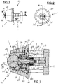
- the keyed device (100) is suitable for being associated with locks (S), in combination with euro profiled cylinders (E), in particular those with so-called "European" profile.
- These locks (S), with the related cylinders (E), are suitable for being installed on security doors of homes and offices, armoured doors of safes or security lockers, and the like (not illustrated), and comprising at least one deadbolt (P) with lock operated by a cam (C) of the cylinder (E) (specifically see Dwg. 12).
- the cam (C) is rotated in either direction, respectively to open or close said deadbolt (P), via the mechanisms of the aforementioned lock (S).
- the device (100) includes a (1) mechanism for operating said cam (C), in which the following is envisaged:
- the actuator plug (10) can slide axially, in opposition to the reaction of spring-loaded components (13), while the manipulator head (11) is inserted rotating in a cylindrical compartment (14) situated in a flange (15), with the latter integral to the afore-mentioned euro profile cylinder (E).
- the mechanical combination means (12) are advantageously made up of a number of combination pins (120) (of which only two visible in Dwg. 3), housed inside said manipulator head (11) and arranged in a circle according to a predefined geometry, for example a circumference, with the respective axes parallel to that of the manipulator head (11).
- each of the combination pins (120) protrude from the rear of the manipulator head (11) beyond the end of the cylindrical compartment (14) and are partially inserted into corresponding holes (16) situated in the flange (15); each of the combination pins (120) is made up of two consecutive parts, the first (121) and the second (122).
- the total emerging length of each combination pin (120) can be the same or differ with respect to that of the remaining pins (120), as can the length of the first part (121) with respect to the second part (122), or with respect to those of the other pins (120).
- At least one of the afore-mentioned combination pins (120) includes a third part (123), for example a spheroid, placed between said first and second parts (121) (122) (Dwg. 3).
- the insertion or removal of the third part (123) makes it possible, conveniently, to modify the combination cuts of the mechanical combination means (12) at a later stage.
- Each combination pin (120) in two parts (121) (122) (or three), is subject to the action of the spring-loaded components (124) inserted in the related hole (16), which drive it axially to protrude from the front side of the manipulator head (11), up until a pre-established position defined by a stop (17) envisaged in the latter.
- the device (100) also comprises an opening/closing assembly (2), accessible from the external side of the afore-mentioned security doors, armoured dolors and the like, intended to operate on the afore-mentioned manipulator head (11) and on the mechanical combination means (12).
- the opening/closing assembly (2) comprises an outer shell (20), incorporating an axial pass-through cylindrical seat (21) that houses a rotor (22) coaxial with said manipulator head (11) and the actuator plug (10).
- the outer shell (20), solidly and robustly constructed in highly-resistant steel, is integral with said euro profile cylinder (E) and protrudes at least partially outward from the related security door, armoured door, or the like.
- the outer shell (20) is ring-shaped and externally formed with decreasing cross-section moving outward from said door, armoured door, or the like, for example tapered as illustrated in the drawings.
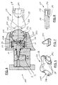
- the rotor (22) is able to slide axially toward the manipulator head (11), in opposition to the spring-loaded components (23) which retain it, when at rest, against a shoulder (24) within the afore-mentioned seat (21).
- the shoulder (24) has a lesser diameter than that of the axial cylindrical seat (21) and is situated near the outermost end of the cylindrical seat.
- a defender block (25), for impeding external access to the manipulator head (11), is supported rotating, by a pin (25P) with an axis perpendicular to the rotation of the rotor (22).
- the defender block (25) is conveniently made of highly-resistant steel, for example in alloy with molybdenum and vanadium, capable of granting the same elevated anti lock-picking and anti-drilling properties.
- the defender block (25) is partially accessible externally and close to said manipulator head (11) with the respective internal part, and in the related lateral surface area presents a first profiled face (251) that can be stably paired with a removable flat key (26), and a second profiled face (252), diametrically opposite to the first, which can be provisionally paired with an opening/closing device (27).
- the aforesaid defender block (25) has an essentially spherical shape where at least the first profiled face (251) is flattened and parallel to the rotation axis of the block (25) itself.
- the latter is composed of two parts (22A, 22B), joined to each other by said rotation pin (25P) of the defender block (25) (Dwgs. 3 and 4).
- the defender block (25) is envisaged to rotate between at least two characteristic positions, one where the first profiled face (251) is turned outward and can receive the flat key (26).
- the first profiled face (251) is turned towards the manipulator head (11) while the second profiled face (252) is turned outward and can receive said opening/closing device (27).
- a male dovetail profile (261) is envisaged, which can engage with a complementary female dovetail profile (262) on the back of the flat key (26) to achieve the stable removable coupling between it and said block (25).
- At least two dead holes (272) are envisaged, parallel to each other and parallel and symmetrically off-centre from the rotation axis of said rotor (22).
- the two afore-mentioned dead holes (272) are there to accommodate corresponding plugs (270) protruding from the opening/closing device (27), to accomplish the provisional coupling between it and the defender block (25) (see in particular Dwg. 4).
- the flat key (26), illustrated in the drawings from 8 to 11 and adapted for the spherical defender block (25), has an outer face shaped like a spherical cap, with radius equal to that of the block (25), so as to restore the continuity of the spherical shape when they are joined together.
- the same spherical cap-shaped outer face of the flat key (26) comprises a number of combination holes (260), of differing lengths, arranged in a circle according to a predefined geometry, for example a circumference, with their axes parallel to each other.
- the combination holes (260) are destined to be directed toward the manipulator head (11) and parallel to its axis in concomitance with said second position of the defender block (25), and are suitable for engaging with the corresponding combination pins (120) protruding from the manipulator head (11) to push them along their predefined routes envisaged to release the head, as more fully explained further on.
- the lateral surface of the defender block (25) envisages a number of notches (25T), that can be gripped by a fingernail or flat-blade tool, to facilitate the rotation of the block (25) between its two characteristic positions (Dwgs. 1, 2, 12).
- respective centring means (30) have been envisaged, represented in the example by an initial circular cavity (31) made in the centre of the flat key (26) and a second circular cavity (32), identical to the first, made in the centre of the second profiled face (252).
- Each cavity (31, 32), in relation to the position adopted by the defender block (25), is alternatively destined to elastically engage with a reference situated in the manipulator head (11), for example the headend of the actuator plug (10), protruding slightly from the latter.
- the afore-mentioned defender block (25) has an essentially cylindrical shape whose axis coincides with the rotation axis of the block (25) itself; likewise, at least the first profiled face (251) is flattened and parallel to the rotation axis.
- the defender block (25) has an essentially prismatic shape whose longitudinal axis coincides with the rotation axis of the block (25) itself, and where the first and second profiled faces (251, 252) coincide with the corresponding lateral faces of the prism.
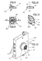
- Dwgs. 4, 5, 6, 7 illustrate the opening/closing device (27) in the form adapted for the described preferred form for creating the defender block (25).
- the opening/closing device (27) can house, within it, the flat key (26) for the transportation of the same, placed in such a way so that the back is presented with the female dovetail profile (262) turned outward.
- the opening/closing device (27) has a main body (28), shaped to provide an ergonomic grip for the fingers of one hand, which envisages: a compartment (29) for holding, retaining and transporting the flat key (26); a cover (29C) for the closure, at least partial, of said compartment (29); coupling means (271) consisting of a cavity shaped to match the second profiled face (252) of the defender block (25) and at least two parallel plugs (270).
- the cover (29C) (Dwg. 7) is extractable, but it is possible to envisage a version in which the same is joined via hinge to the main body (28).
- the cavity of the coupling means (271) adopts a concave form with a spherical radius equal to that of the defender block (25) and contains, appropriately positioned and protruding outward, the afore-mentioned plugs (270) which, as already mentioned above, can be inserted in the aforesaid dead holes (272) in the second profiled! face (252), so as to accomplish the provisional coupling between said device (27) and the defender block (25).
- the flat key (26) remains stably engaged in the defender block (25), which is subsequently rotated, again with the possible aid of the notches (25T), in its afore-mentioned second position, in which the same flat key (26) is drawn inside, in front of the manipulator head (11).
- the plugs (270) engage in the dead holes (272) of the second profiled face (252), until the concave cavity joins the spherical defender block (25).
- Another advantage derives from having made the area in which the flat key of the device presents its cuts to the mechanical combination means inaccessible from outside, as well as well protected from attacks of elevated force.
- the construction-related aspect just mentioned also prevents any action aimed at the reverse detection of the correct combination cut of the key, with a considerable increase in security.
- the structure of the keyed device described makes it possible to combine it with additional accessory devices, both mechanical and electromechanical, aimed at further increasing the security of the same.
Landscapes
- Engineering & Computer Science (AREA)
- Mechanical Engineering (AREA)
- Lock And Its Accessories (AREA)
- Manipulator (AREA)
Claims (15)
- Schlüsselvorrichtung zum Betätigen von Schlössern (S), die Euro-Profilzylinder (E) enthalten, zum Einbau in Sicherheitstüren, Panzertüren und dergleichen geeignet sind und mindestens einen zylinderbetätigten Schließriegel (P) umfassen, wobei der Zylinder (E) einen Mitnehmer (C) umfasst, der in beide Richtungen gedreht werden kann, um den mindestens einen Schließriegel (P) zu öffnen beziehungsweise zu schließen, und wobei diese Vorrichtung (100) umfasst:- einen Mechanismus (1) zum Betätigen des Mitnehmers (C), umfassend: eine in dem Euro-Profilzylinder (E) angeordnete und mit der Drehachse des Mitnehmers (C) koaxiale Antriebswelle (10), die bewirkt, dass sich der Mitnehmer dreht; einen Steuerkopf (11), der mit der Antriebswelle (10) verbunden ist und die Drehung der Welle bewirkt; mechanische Kombinationsmittel (12) zum Blockieren und Freigeben der Drehung des Steuerkopfs (11) und der angeschlossenen Antriebswelle (10);- eine Öffnungs-/Schließanordnung (2), die von der Außenseite der Sicherheitstüren, Panzertüren und dergleichen zum Betätigen des Steuerkopfs (11) und der mechanischen Kombinationsmittel (12) zugänglich ist, wobei die Öffnungs-/Schließanordnung (2) umfasst: eine äußere Schale (20), die einen axial durchlaufenden zylindrischen Sitz (21) enthält, dadurch gekennzeichnet, dass der axial durchlaufende zylindrische Sitz (21) einen Rotor (22) beherbergt, der koaxial mit dem Steuerkopf (11) und der Antriebswelle (10) ist, wobei der Rotor (22) axial in Richtung des Steuerkopfs (11) entgegen den federbeaufschlagten Elementen (23) gleiten kann, die ihn im Ruhezustand gegen eine Schulter (24) in dem zylindrischen Sitz (21) zurückhalten; einen Schutzblock (25) zum Verhindern des Zugangs von außen zum Steuerkopf (11), der von einem Zapfen (25P) in dem Rotor (22) getragen wird und imstande ist, sich auf einer zur Drehung des Rotors (22) perpendikularen Achse zu drehen, wobei der Schutzblock (25) teilweise von außen zugänglich ist und sich mit seinem entsprechenden Innenteil nahe dem Steuerkopf (11) befindet und wobei der Schutzblock (25) eine erste profilierte Fläche (251), die stabil mit einem entfernbaren Flachschlüssel (26) zusammengepasst werden kann, und eine der ersten diametral gegenüberliegende zweite profilierte Fläche (252) umfasst, die provisorisch mit einem Verriegelungs-/Entriegelungswerkzeug (27) zusammengepasst werden kann, und wobei sich der Schutzblock (25) zwischen mindestens zwei charakteristischen Stellungen drehen kann, einer, in der die erste profilierte Fläche (251) nach außen gedreht ist und den Flachschlüssel (26) aufnehmen kann, und einer anderen, in der die erste profilierte Fläche (251) zum Steuerkopf (11) hin gedreht ist, während die zweite profilierte Fläche (252) nach außen gedreht ist und das Verriegelungs-/Entriegelungswerkzeug (27) aufnehmen kann, das von Hand betätigt werden kann, um Folgendes zu bewirken: die axiale Verstellung der Gruppe Rotor/Schutzblock/Flachschlüssel (22, 25, 26) derart, dass der Schlüssel in die mechanischen Kombinationsmittel (12) eingreift, um die Drehung des Steuerkopfs (11) freizugeben; die Drehung, in der einen oder der anderen Richtung, der Gruppe Rotor/Schutzblock/Flachschlüssel/Steuerkopf/Antriebswelle (22, 25, 26, 11, 10) mit daraus resultierender Drehung in der gleichen Richtung des Mitnehmers (C) zum Öffnen oder Schließen des Schlosses (S).
- Schlüsselvorrichtung nach Anspruch 1, dadurch gekennzeichnet, dass die Antriebswelle (10) in dem Betätigungsmechanismus (1) entgegen federbeaufschlagten Elementen (13) und gleichzeitig mit der vorgenannten axialen Verstellung der Gruppe Rotor/Schutzblock/Flachschlüssel (22, 25, 26) axial gleiten kann, wobei der Steuerkopf (11) eingeführt ist und sich in einer zylindrischen Aufnahme (14) drehen kann, die sich in einem Flansch (15) befindet, der in den Euro-Profilzylinder (E) eingebaut ist, und wobei die mechanischen Kombinationsmittel (12) aus einer Reihe von Kombinationsstiften (120) bestehen, die in dem Steuerkopf (11) untergebracht sind, in einem Kreis gemäß einer vorgegebenen Geometrie mit ihren Achsen parallel zu der des Steuerkopfs (11) angeordnet sind und von der Rückseite des Kopfs über das Ende der zylindrischen Aufnahme (14) hinaus vorstehen sowie teilweise in entsprechende Löcher (16) in dem Flansch (15) eingefügt sind, wobei jeder der Kombinationsstifte (120) derart aus zwei aufeinanderfolgenden Teilen, einem ersten (121) und einem zweiten (122), besteht, dass die Gesamtlänge gleich der der übrigen Stifte (120) sein kann oder sich davon unterscheiden kann, und wobei der aus zwei Teilen (121, 122) bestehende Kombinationsstift (120) der Wirkung von federbeaufschlagten Elementen (124) ausgesetzt ist und entgegen den federbeaufschlagten Elementen axial über eine vorgegebene Weglänge, die von den Einschnitten des Flachschlüssels (26) bestimmt wird, geschoben wird, um eine Position zu erreichen, in der die diametrale Ebene, in der die benachbarten ersten und zweiten Teile (121, 122) der Stifte aufeinandertreffen, bündig mit dem Ende der zylindrischen Aufnahme (14) ist, wodurch es dem Steuerkopf (11) ermöglicht wird, sich zusammen mit der Antriebswelle (10) zu drehen und alle ersten Teile (121) der Kombinationsstifte (120) von ihren jeweiligen zweiten Teilen (122) winklig zu trennen, die in den Löchern (16) in dem Flansch (15) verbleiben.
- Schlüsselvorrichtung nach Anspruch 1, dadurch gekennzeichnet, dass die äußere Schale (20) in der Öffnungs-/Schließanordnung (2) einstückig mit dem Euro-Profilzylinder (E) ist und zumindest teilweise von einer Sicherheitstür, Panzertür oder dergleichen nach außen vorsteht, wobei die äußere Schale (20) ein ringförmiges Äußeres mit in Richtung der Außenseite der Tür, Panzertür oder dergleichen abnehmendem Querschnitt aufweist, wobei die Schulter (24) einen kleineren Durchmesser als der axiale zylindrische Sitz (21) hat und nahe dem äußersten Ende des zylindrischen Sitzes angeordnet ist.
- Schlüsselvorrichtung nach Anspruch 1, dadurch gekennzeichnet, dass der Schutzblock (25) eine im Wesentlichen sphärische Form hat, bei der zumindest die erste profilierte Fläche (251) abgeflacht und parallel zur Drehachse des Blocks (25) ist.
- Schlüsselvorrichtung nach Anspruch 1 oder 4, dadurch gekennzeichnet, dass der Flachschlüssel (26) eine Außenfläche hat, die wie eine sphärische Kappe mit einem Radius, der gleich dem des Blocks (25) ist, geformt ist, um eine vollständige Kugelform zu bilden, wenn sie miteinander verbunden sind, wobei dieselbe Außenfläche des Flachschlüssels (26) eine Reihe von Kombinationslöchern (260) unterschiedlicher Tiefe umfasst, die in einem Kreis gemäß einer vorgegebenen Geometrie mit ihren Achsen parallel zueinander angeordnet sind, und die zum Steuerkopf (11) hin gerichtet und parallel zu seiner Achse in Übereinstimmung mit der zweiten Stellung des Schutzblocks (25) sind, sodass die Kombinationslöcher (260) mit den entsprechenden Stiften (120), die von dem Steuerkopf (11) vorstehen, in Eingriff sind, um sie entlang ihrem vorgegebenen Weg zu schieben, um den Kopf freizugeben.
- Schlüsselvorrichtung nach Anspruch 1 oder 4, dadurch gekennzeichnet, dass der Rotor (22) aus zwei Teilen (22A, 22B) besteht, die vom Drehbolzen (25P) des Schutzblocks (25) miteinander verbunden werden.
- Schlüsselvorrichtung nach Anspruch 1, dadurch gekennzeichnet, dass der Schutzblock (25) eine im Wesentlichen zylindrische Form hat, deren Achse mit der Drehachse des Blocks (25) zusammenfällt, und wobei zumindest die erste profilierte Fläche (251) abgeflacht und parallel zur Drehachse ist.
- Schlüsselvorrichtung nach Anspruch 1, dadurch gekennzeichnet, dass der Schutzblock (25) im Wesentlichen die Form eines rechteckigen Prismas hat, dessen Längsachse mit der Drehachse des Blocks (25) zusammenfällt, und wobei die erste und die zweite profilierte Fläche (251, 252) mit den entsprechenden Flächen des rechteckigen Prismas übereinstimmen.
- Schlüsselvorrichtung nach einem der vorhergehenden Ansprüche, dadurch gekennzeichnet, dass die Seitenfläche des Schutzblocks (25) eine Reihe von Kerben (25T) umfasst, in die mit einem Fingernagel oder einem Werkzeug mit flacher Klinge eingegriffen werden kann, um die Drehung des Blocks (25) zwischen seinen zwei charakteristischen Stellungen zu bewirken.
- Schlüsselvorrichtung nach einem der vorhergehenden Ansprüche, dadurch gekennzeichnet, dass die erste profilierte Fläche (251) des Schutzblocks (25) ein männliches Schwalbenschwanzprofil (261) aufweist, das in ein komplementäres weibliches Schwalbenschwanzprofil (262) auf der Rückseite des Flachschlüssels (26) eingreifen kann, um die stabile lösbare Verbindung zwischen ihm und dem Block (25) herzustellen.
- Schlüsselvorrichtung nach einem der vorhergehenden Ansprüche, dadurch gekennzeichnet, dass die zweite profilierte Fläche (252) des Schutzblocks (25) mindestens zwei Sacklöcher (272) aufweist, die parallel zueinander und symmetrisch außermittig zur Drehachse des Rotors (22) sind, wobei die mindestens zwei Sacklöcher (272) entsprechende Stecker (270) aufnehmen können, die aus dem Verriegelungs-/Entriegelungswerkzeug (27) herausragen, um die provisorische Verbindung zwischen ihm und dem Block (25) herzustellen.
- Schlüsselvorrichtung nach einem der vorhergehenden Ansprüche, dadurch gekennzeichnet, dass der Flachschlüssel (26) und die zweite profilierte Fläche (252) beide einander identische Zentriermittel (30) aufweisen, die wechselweise elastisch in eine Referenz eingreifen können, die sich im Steuerkopf (11) befindet, um die zwei charakteristischen Stellungen des Schutzblocks (25) zu definieren und zu stabilisieren.
- Schlüssefvorrichtung nach einem der vorhergehenden Ansprüche, dadurch gekennzeichnet, dass der Hauptkörper (28) des Verriegelungs-/Entriegelungswerkzeugs (27) ein Fach (29) zum Aufnehmen, Zurückhalten und Transportieren des Flachschlüssels (26) und eine Abdeckung (29C) zum zumindest teilweisen Verschließen des Fachs (29) aufweist,
- Flachschlüssel (26) zur Verwendung mit einer Schlüsselvorrichtung (100) zum Betätigen von Schlössern (S) nach einem der Ansprüche 1 bis 10, dadurch gekennzeichnet, dass er umfasst: eine Reihe von Kombinationslöchem (260) unterschiedlicher Tiefe, die in einem Kreis gemäß einer vorgegebenen Geometrie mit ihren Achsen parallel zueinander angeordnet sind und die zum Steuerkopf (11) hin und parallel zu seiner Achse in Übereinstimmung mit der zweiten Stellung des Schutzblocks (25) gerichtet sein können, wobei sich die Kombinationslöcher (260) mit den entsprechenden Kombinationsstiften (120), die vom Steuerkopf (11) vorstehen, verbinden können, um sie entlang den vorgegebenen Wegen zum Freigeben des Kopfs zu schieben; wobei sich ein weibliches Schwalbenschwanzprofil (262) entlang der Rückseite des Flachschlüssels (26) mit einem komplementären männlichen Schwalbenschwanzprofil (261) in dem Schutzblock (25) verbinden kann, um eine stabile und lösbare Verbindung zwischen ihnen herzustellen.
- Verriegelungs-/Entriegelungswerkzeug (27) zur Verwendung mit einer Schlüsselvorrichtung (100) zum Betätigen von Schlössern (S) nach einem der Ansprüche 1 bis 10, dadurch gekennzeichnet, dass es einen Hauptkörper (28) hat, der derart geformt ist, dass er einen ergonomischen Griff für die Finger einer Hand bereitstellt, und der umfasst: ein Fach (29) zum Aufnehmen, Zurückhalten und Transportieren des Flachschlüssels (26); Verbindungsmittel (271), die aus einem Hohlraum, der derart geformt ist, dass er mit der zweiten profilierten Fläche (252) des Schutzblocks (25) zusammenpasst, und mindestens zwei parallelen Steckern (270) bestehen, die nach außen vorstehen und in die entsprechenden Sacklöcher (272) in der zweiten profilierten Fläche (252) eingeführt werden können, um die provisorische Verbindung zwischen dem Werkzeug (27) und dem Block (25) herzustellen.
Applications Claiming Priority (2)
| Application Number | Priority Date | Filing Date | Title |
|---|---|---|---|
| IT102016000105693A IT201600105693A1 (it) | 2016-10-20 | 2016-10-20 | Dispositivo a chiave per l'azionamento di serrature |
| PCT/IB2017/001278 WO2018073641A1 (en) | 2016-10-20 | 2017-10-20 | Keyed device for operating locks |
Publications (2)
| Publication Number | Publication Date |
|---|---|
| EP3529435A1 EP3529435A1 (de) | 2019-08-28 |
| EP3529435B1 true EP3529435B1 (de) | 2020-10-14 |
Family
ID=58010252
Family Applications (1)
| Application Number | Title | Priority Date | Filing Date |
|---|---|---|---|
| EP17835489.0A Active EP3529435B1 (de) | 2016-10-20 | 2017-10-20 | Schlüsselgerät zum betrieb von schlössern |
Country Status (4)
| Country | Link |
|---|---|
| EP (1) | EP3529435B1 (de) |
| CN (1) | CN109863278B (de) |
| IT (1) | IT201600105693A1 (de) |
| WO (1) | WO2018073641A1 (de) |
Families Citing this family (1)
| Publication number | Priority date | Publication date | Assignee | Title |
|---|---|---|---|---|
| CN119403989B (zh) * | 2022-06-30 | 2026-01-02 | 帝拉克五金有限公司 | 磁性加密的锁 |
Family Cites Families (11)
| Publication number | Priority date | Publication date | Assignee | Title |
|---|---|---|---|---|
| DE667248C (de) * | 1934-09-04 | 1938-11-08 | Helene Sewoll Geb Schlitz | Schloss |
| US3630053A (en) * | 1970-04-01 | 1971-12-28 | Edwin G Krakauer | Safety lock |
| US3680337A (en) * | 1971-03-09 | 1972-08-01 | Edwin G Krakauer | Safety lock |
| IT977537B (it) * | 1973-02-27 | 1974-09-20 | Jacovacci A | Serratura di sicurezza |
| US4006615A (en) * | 1975-08-07 | 1977-02-08 | Janos Szova | Axial tumbler lock |
| DE29619390U1 (de) * | 1996-01-23 | 1997-03-20 | Kolb, Horst, 93049 Regensburg | Bedieneinrichtung für Vorsatzschlösser von Schloßzylindern |
| US5934122A (en) * | 1998-05-20 | 1999-08-10 | Sure-Wood Lock, Inc. | Locking cover for dead bolt actuators |
| US6393883B1 (en) * | 2000-03-02 | 2002-05-28 | Royal Lock Corp. | Tubular keyed cam lock with screw attachment |
| FR2882463B1 (fr) * | 2005-02-24 | 2007-03-30 | Schneider Electric Ind Sas | Bouton tournant a serrure |
| CN201053250Y (zh) * | 2007-06-26 | 2008-04-30 | 赵北华 | 带钥匙输送器的门插锁 |
| GB2512274A (en) * | 2013-02-08 | 2014-10-01 | William Frederick Crosbie | Rotational pin lock |
-
2016
- 2016-10-20 IT IT102016000105693A patent/IT201600105693A1/it unknown
-
2017
- 2017-10-20 CN CN201780064689.6A patent/CN109863278B/zh not_active Expired - Fee Related
- 2017-10-20 WO PCT/IB2017/001278 patent/WO2018073641A1/en not_active Ceased
- 2017-10-20 EP EP17835489.0A patent/EP3529435B1/de active Active
Non-Patent Citations (1)
| Title |
|---|
| None * |
Also Published As
| Publication number | Publication date |
|---|---|
| IT201600105693A1 (it) | 2018-04-20 |
| CN109863278A (zh) | 2019-06-07 |
| WO2018073641A1 (en) | 2018-04-26 |
| EP3529435A1 (de) | 2019-08-28 |
| CN109863278B (zh) | 2020-10-16 |
Similar Documents
| Publication | Publication Date | Title |
|---|---|---|
| US9556651B1 (en) | Electronic sensor and key operated lock | |
| US10422163B1 (en) | Electronic sensor and key operated lock | |
| EP2942456B1 (de) | Diebstahlsicheres schloss | |
| CN102971469A (zh) | 锁具机构 | |
| US20110067461A1 (en) | Lockable enclosure | |
| US20070289342A1 (en) | Electronic restraint system | |
| PL2176477T3 (pl) | Zamek odryglowywany elektrycznie w sposób zautomatyzowany, zwłaszcza do systemów przechowywania w rodzaju skrytki pocztowej | |
| US20130154462A1 (en) | Door locking apparatus and an enclosure having the same | |
| US10066419B2 (en) | Cylinder lock and combination of such a lock and key | |
| GB2549193A (en) | A lock | |
| EP2476825A2 (de) | Verriegelungssystem für eine Schranktür | |
| GB2556336A (en) | Improvements to lock cylinders | |
| EP3529435B1 (de) | Schlüsselgerät zum betrieb von schlössern | |
| CN215927048U (zh) | 指旋锁执行器 | |
| AU2016429210B2 (en) | Security lock | |
| EP1785572B1 (de) | Verriegelungsvorrichtung für Schränke für öffentliche Telefone | |
| EP3670791B1 (de) | Verriegelungsanordnung | |
| WO2007099523A2 (en) | Attack resistant double cylinder lock | |
| CN204941083U (zh) | 钉子孔防盗锁具与配套钥匙 | |
| US20150135781A1 (en) | Locking system | |
| US7339472B2 (en) | Self-adjusting cam assembly | |
| EP1785573B1 (de) | Verriegelungsvorrichtung für Schränke für öffentliche Telefone | |
| US12012779B1 (en) | Electronic sensor and key operated lock | |
| US9745774B2 (en) | Lock cylinder | |
| EP4624707A1 (de) | Verriegelungskupplung |
Legal Events
| Date | Code | Title | Description |
|---|---|---|---|
| STAA | Information on the status of an ep patent application or granted ep patent |
Free format text: STATUS: UNKNOWN |
|
| STAA | Information on the status of an ep patent application or granted ep patent |
Free format text: STATUS: THE INTERNATIONAL PUBLICATION HAS BEEN MADE |
|
| PUAI | Public reference made under article 153(3) epc to a published international application that has entered the european phase |
Free format text: ORIGINAL CODE: 0009012 |
|
| STAA | Information on the status of an ep patent application or granted ep patent |
Free format text: STATUS: REQUEST FOR EXAMINATION WAS MADE |
|
| 17P | Request for examination filed |
Effective date: 20190516 |
|
| AK | Designated contracting states |
Kind code of ref document: A1 Designated state(s): AL AT BE BG CH CY CZ DE DK EE ES FI FR GB GR HR HU IE IS IT LI LT LU LV MC MK MT NL NO PL PT RO RS SE SI SK SM TR |
|
| AX | Request for extension of the european patent |
Extension state: BA ME |
|
| DAV | Request for validation of the european patent (deleted) | ||
| DAX | Request for extension of the european patent (deleted) | ||
| GRAP | Despatch of communication of intention to grant a patent |
Free format text: ORIGINAL CODE: EPIDOSNIGR1 |
|
| STAA | Information on the status of an ep patent application or granted ep patent |
Free format text: STATUS: GRANT OF PATENT IS INTENDED |
|
| INTG | Intention to grant announced |
Effective date: 20200603 |
|
| GRAS | Grant fee paid |
Free format text: ORIGINAL CODE: EPIDOSNIGR3 |
|
| GRAA | (expected) grant |
Free format text: ORIGINAL CODE: 0009210 |
|
| STAA | Information on the status of an ep patent application or granted ep patent |
Free format text: STATUS: THE PATENT HAS BEEN GRANTED |
|
| AK | Designated contracting states |
Kind code of ref document: B1 Designated state(s): AL AT BE BG CH CY CZ DE DK EE ES FI FR GB GR HR HU IE IS IT LI LT LU LV MC MK MT NL NO PL PT RO RS SE SI SK SM TR |
|
| REG | Reference to a national code |
Ref country code: GB Ref legal event code: FG4D |
|
| REG | Reference to a national code |
Ref country code: AT Ref legal event code: REF Ref document number: 1323731 Country of ref document: AT Kind code of ref document: T Effective date: 20201015 Ref country code: CH Ref legal event code: EP |
|
| REG | Reference to a national code |
Ref country code: CH Ref legal event code: NV Representative=s name: KATZAROV SA, CH |
|
| REG | Reference to a national code |
Ref country code: DE Ref legal event code: R096 Ref document number: 602017025652 Country of ref document: DE |
|
| REG | Reference to a national code |
Ref country code: IE Ref legal event code: FG4D |
|
| REG | Reference to a national code |
Ref country code: AT Ref legal event code: MK05 Ref document number: 1323731 Country of ref document: AT Kind code of ref document: T Effective date: 20201014 |
|
| REG | Reference to a national code |
Ref country code: NL Ref legal event code: MP Effective date: 20201014 |
|
| PG25 | Lapsed in a contracting state [announced via postgrant information from national office to epo] |
Ref country code: PT Free format text: LAPSE BECAUSE OF FAILURE TO SUBMIT A TRANSLATION OF THE DESCRIPTION OR TO PAY THE FEE WITHIN THE PRESCRIBED TIME-LIMIT Effective date: 20210215 Ref country code: RS Free format text: LAPSE BECAUSE OF FAILURE TO SUBMIT A TRANSLATION OF THE DESCRIPTION OR TO PAY THE FEE WITHIN THE PRESCRIBED TIME-LIMIT Effective date: 20201014 Ref country code: FI Free format text: LAPSE BECAUSE OF FAILURE TO SUBMIT A TRANSLATION OF THE DESCRIPTION OR TO PAY THE FEE WITHIN THE PRESCRIBED TIME-LIMIT Effective date: 20201014 Ref country code: NO Free format text: LAPSE BECAUSE OF FAILURE TO SUBMIT A TRANSLATION OF THE DESCRIPTION OR TO PAY THE FEE WITHIN THE PRESCRIBED TIME-LIMIT Effective date: 20210114 Ref country code: GR Free format text: LAPSE BECAUSE OF FAILURE TO SUBMIT A TRANSLATION OF THE DESCRIPTION OR TO PAY THE FEE WITHIN THE PRESCRIBED TIME-LIMIT Effective date: 20210115 |
|
| REG | Reference to a national code |
Ref country code: LT Ref legal event code: MG4D |
|
| PG25 | Lapsed in a contracting state [announced via postgrant information from national office to epo] |
Ref country code: BG Free format text: LAPSE BECAUSE OF FAILURE TO SUBMIT A TRANSLATION OF THE DESCRIPTION OR TO PAY THE FEE WITHIN THE PRESCRIBED TIME-LIMIT Effective date: 20210114 Ref country code: IS Free format text: LAPSE BECAUSE OF FAILURE TO SUBMIT A TRANSLATION OF THE DESCRIPTION OR TO PAY THE FEE WITHIN THE PRESCRIBED TIME-LIMIT Effective date: 20210214 Ref country code: LV Free format text: LAPSE BECAUSE OF FAILURE TO SUBMIT A TRANSLATION OF THE DESCRIPTION OR TO PAY THE FEE WITHIN THE PRESCRIBED TIME-LIMIT Effective date: 20201014 Ref country code: PL Free format text: LAPSE BECAUSE OF FAILURE TO SUBMIT A TRANSLATION OF THE DESCRIPTION OR TO PAY THE FEE WITHIN THE PRESCRIBED TIME-LIMIT Effective date: 20201014 Ref country code: SE Free format text: LAPSE BECAUSE OF FAILURE TO SUBMIT A TRANSLATION OF THE DESCRIPTION OR TO PAY THE FEE WITHIN THE PRESCRIBED TIME-LIMIT Effective date: 20201014 Ref country code: AT Free format text: LAPSE BECAUSE OF FAILURE TO SUBMIT A TRANSLATION OF THE DESCRIPTION OR TO PAY THE FEE WITHIN THE PRESCRIBED TIME-LIMIT Effective date: 20201014 Ref country code: ES Free format text: LAPSE BECAUSE OF FAILURE TO SUBMIT A TRANSLATION OF THE DESCRIPTION OR TO PAY THE FEE WITHIN THE PRESCRIBED TIME-LIMIT Effective date: 20201014 |
|
| PG25 | Lapsed in a contracting state [announced via postgrant information from national office to epo] |
Ref country code: LU Free format text: LAPSE BECAUSE OF NON-PAYMENT OF DUE FEES Effective date: 20201020 Ref country code: NL Free format text: LAPSE BECAUSE OF FAILURE TO SUBMIT A TRANSLATION OF THE DESCRIPTION OR TO PAY THE FEE WITHIN THE PRESCRIBED TIME-LIMIT Effective date: 20201014 Ref country code: HR Free format text: LAPSE BECAUSE OF FAILURE TO SUBMIT A TRANSLATION OF THE DESCRIPTION OR TO PAY THE FEE WITHIN THE PRESCRIBED TIME-LIMIT Effective date: 20201014 |
|
| REG | Reference to a national code |
Ref country code: DE Ref legal event code: R097 Ref document number: 602017025652 Country of ref document: DE Ref country code: BE Ref legal event code: MM Effective date: 20201031 |
|
| PG25 | Lapsed in a contracting state [announced via postgrant information from national office to epo] |
Ref country code: SM Free format text: LAPSE BECAUSE OF FAILURE TO SUBMIT A TRANSLATION OF THE DESCRIPTION OR TO PAY THE FEE WITHIN THE PRESCRIBED TIME-LIMIT Effective date: 20201014 Ref country code: MC Free format text: LAPSE BECAUSE OF FAILURE TO SUBMIT A TRANSLATION OF THE DESCRIPTION OR TO PAY THE FEE WITHIN THE PRESCRIBED TIME-LIMIT Effective date: 20201014 Ref country code: LT Free format text: LAPSE BECAUSE OF FAILURE TO SUBMIT A TRANSLATION OF THE DESCRIPTION OR TO PAY THE FEE WITHIN THE PRESCRIBED TIME-LIMIT Effective date: 20201014 Ref country code: EE Free format text: LAPSE BECAUSE OF FAILURE TO SUBMIT A TRANSLATION OF THE DESCRIPTION OR TO PAY THE FEE WITHIN THE PRESCRIBED TIME-LIMIT Effective date: 20201014 Ref country code: CZ Free format text: LAPSE BECAUSE OF FAILURE TO SUBMIT A TRANSLATION OF THE DESCRIPTION OR TO PAY THE FEE WITHIN THE PRESCRIBED TIME-LIMIT Effective date: 20201014 Ref country code: SK Free format text: LAPSE BECAUSE OF FAILURE TO SUBMIT A TRANSLATION OF THE DESCRIPTION OR TO PAY THE FEE WITHIN THE PRESCRIBED TIME-LIMIT Effective date: 20201014 Ref country code: RO Free format text: LAPSE BECAUSE OF FAILURE TO SUBMIT A TRANSLATION OF THE DESCRIPTION OR TO PAY THE FEE WITHIN THE PRESCRIBED TIME-LIMIT Effective date: 20201014 |
|
| PLBE | No opposition filed within time limit |
Free format text: ORIGINAL CODE: 0009261 |
|
| STAA | Information on the status of an ep patent application or granted ep patent |
Free format text: STATUS: NO OPPOSITION FILED WITHIN TIME LIMIT |
|
| PG25 | Lapsed in a contracting state [announced via postgrant information from national office to epo] |
Ref country code: DK Free format text: LAPSE BECAUSE OF FAILURE TO SUBMIT A TRANSLATION OF THE DESCRIPTION OR TO PAY THE FEE WITHIN THE PRESCRIBED TIME-LIMIT Effective date: 20201014 Ref country code: BE Free format text: LAPSE BECAUSE OF NON-PAYMENT OF DUE FEES Effective date: 20201031 |
|
| 26N | No opposition filed |
Effective date: 20210715 |
|
| PG25 | Lapsed in a contracting state [announced via postgrant information from national office to epo] |
Ref country code: AL Free format text: LAPSE BECAUSE OF FAILURE TO SUBMIT A TRANSLATION OF THE DESCRIPTION OR TO PAY THE FEE WITHIN THE PRESCRIBED TIME-LIMIT Effective date: 20201014 Ref country code: IE Free format text: LAPSE BECAUSE OF NON-PAYMENT OF DUE FEES Effective date: 20201020 |
|
| PG25 | Lapsed in a contracting state [announced via postgrant information from national office to epo] |
Ref country code: SI Free format text: LAPSE BECAUSE OF FAILURE TO SUBMIT A TRANSLATION OF THE DESCRIPTION OR TO PAY THE FEE WITHIN THE PRESCRIBED TIME-LIMIT Effective date: 20201014 |
|
| PGFP | Annual fee paid to national office [announced via postgrant information from national office to epo] |
Ref country code: FR Payment date: 20211116 Year of fee payment: 5 Ref country code: DE Payment date: 20211130 Year of fee payment: 5 Ref country code: GB Payment date: 20211116 Year of fee payment: 5 |
|
| PGFP | Annual fee paid to national office [announced via postgrant information from national office to epo] |
Ref country code: IT Payment date: 20211029 Year of fee payment: 5 Ref country code: CH Payment date: 20211201 Year of fee payment: 5 |
|
| PG25 | Lapsed in a contracting state [announced via postgrant information from national office to epo] |
Ref country code: IS Free format text: LAPSE BECAUSE OF FAILURE TO SUBMIT A TRANSLATION OF THE DESCRIPTION OR TO PAY THE FEE WITHIN THE PRESCRIBED TIME-LIMIT Effective date: 20210214 Ref country code: TR Free format text: LAPSE BECAUSE OF FAILURE TO SUBMIT A TRANSLATION OF THE DESCRIPTION OR TO PAY THE FEE WITHIN THE PRESCRIBED TIME-LIMIT Effective date: 20201014 Ref country code: MT Free format text: LAPSE BECAUSE OF FAILURE TO SUBMIT A TRANSLATION OF THE DESCRIPTION OR TO PAY THE FEE WITHIN THE PRESCRIBED TIME-LIMIT Effective date: 20201014 Ref country code: CY Free format text: LAPSE BECAUSE OF FAILURE TO SUBMIT A TRANSLATION OF THE DESCRIPTION OR TO PAY THE FEE WITHIN THE PRESCRIBED TIME-LIMIT Effective date: 20201014 |
|
| PG25 | Lapsed in a contracting state [announced via postgrant information from national office to epo] |
Ref country code: MK Free format text: LAPSE BECAUSE OF FAILURE TO SUBMIT A TRANSLATION OF THE DESCRIPTION OR TO PAY THE FEE WITHIN THE PRESCRIBED TIME-LIMIT Effective date: 20201014 |
|
| REG | Reference to a national code |
Ref country code: DE Ref legal event code: R119 Ref document number: 602017025652 Country of ref document: DE |
|
| REG | Reference to a national code |
Ref country code: CH Ref legal event code: PL |
|
| GBPC | Gb: european patent ceased through non-payment of renewal fee |
Effective date: 20221020 |
|
| PG25 | Lapsed in a contracting state [announced via postgrant information from national office to epo] |
Ref country code: LI Free format text: LAPSE BECAUSE OF NON-PAYMENT OF DUE FEES Effective date: 20221031 Ref country code: FR Free format text: LAPSE BECAUSE OF NON-PAYMENT OF DUE FEES Effective date: 20221031 Ref country code: DE Free format text: LAPSE BECAUSE OF NON-PAYMENT OF DUE FEES Effective date: 20230503 Ref country code: CH Free format text: LAPSE BECAUSE OF NON-PAYMENT OF DUE FEES Effective date: 20221031 |
|
| PG25 | Lapsed in a contracting state [announced via postgrant information from national office to epo] |
Ref country code: IT Free format text: LAPSE BECAUSE OF NON-PAYMENT OF DUE FEES Effective date: 20221020 Ref country code: GB Free format text: LAPSE BECAUSE OF NON-PAYMENT OF DUE FEES Effective date: 20221020 |