EP3529113B1 - Lateral dynamic control for regenerative and friction brake blending - Google Patents
Lateral dynamic control for regenerative and friction brake blending Download PDFInfo
- Publication number
- EP3529113B1 EP3529113B1 EP17784924.7A EP17784924A EP3529113B1 EP 3529113 B1 EP3529113 B1 EP 3529113B1 EP 17784924 A EP17784924 A EP 17784924A EP 3529113 B1 EP3529113 B1 EP 3529113B1
- Authority
- EP
- European Patent Office
- Prior art keywords
- vehicle
- wheels
- axle
- braking force
- estimated
- Prior art date
- Legal status (The legal status is an assumption and is not a legal conclusion. Google has not performed a legal analysis and makes no representation as to the accuracy of the status listed.)
- Active
Links
Images



Classifications
-
- B—PERFORMING OPERATIONS; TRANSPORTING
- B60—VEHICLES IN GENERAL
- B60T—VEHICLE BRAKE CONTROL SYSTEMS OR PARTS THEREOF; BRAKE CONTROL SYSTEMS OR PARTS THEREOF, IN GENERAL; ARRANGEMENT OF BRAKING ELEMENTS ON VEHICLES IN GENERAL; PORTABLE DEVICES FOR PREVENTING UNWANTED MOVEMENT OF VEHICLES; VEHICLE MODIFICATIONS TO FACILITATE COOLING OF BRAKES
- B60T8/00—Arrangements for adjusting wheel-braking force to meet varying vehicular or ground-surface conditions, e.g. limiting or varying distribution of braking force
- B60T8/17—Using electrical or electronic regulation means to control braking
- B60T8/1755—Brake regulation specially adapted to control the stability of the vehicle, e.g. taking into account yaw rate or transverse acceleration in a curve
- B60T8/17552—Brake regulation specially adapted to control the stability of the vehicle, e.g. taking into account yaw rate or transverse acceleration in a curve responsive to the tyre sideslip angle or the vehicle body slip angle
-
- B—PERFORMING OPERATIONS; TRANSPORTING
- B60—VEHICLES IN GENERAL
- B60L—PROPULSION OF ELECTRICALLY-PROPELLED VEHICLES; SUPPLYING ELECTRIC POWER FOR AUXILIARY EQUIPMENT OF ELECTRICALLY-PROPELLED VEHICLES; ELECTRODYNAMIC BRAKE SYSTEMS FOR VEHICLES IN GENERAL; MAGNETIC SUSPENSION OR LEVITATION FOR VEHICLES; MONITORING OPERATING VARIABLES OF ELECTRICALLY-PROPELLED VEHICLES; ELECTRIC SAFETY DEVICES FOR ELECTRICALLY-PROPELLED VEHICLES
- B60L7/00—Electrodynamic brake systems for vehicles in general
- B60L7/24—Electrodynamic brake systems for vehicles in general with additional mechanical or electromagnetic braking
- B60L7/26—Controlling the braking effect
-
- B—PERFORMING OPERATIONS; TRANSPORTING
- B60—VEHICLES IN GENERAL
- B60T—VEHICLE BRAKE CONTROL SYSTEMS OR PARTS THEREOF; BRAKE CONTROL SYSTEMS OR PARTS THEREOF, IN GENERAL; ARRANGEMENT OF BRAKING ELEMENTS ON VEHICLES IN GENERAL; PORTABLE DEVICES FOR PREVENTING UNWANTED MOVEMENT OF VEHICLES; VEHICLE MODIFICATIONS TO FACILITATE COOLING OF BRAKES
- B60T13/00—Transmitting braking action from initiating means to ultimate brake actuator with power assistance or drive; Brake systems incorporating such transmitting means, e.g. air-pressure brake systems
- B60T13/10—Transmitting braking action from initiating means to ultimate brake actuator with power assistance or drive; Brake systems incorporating such transmitting means, e.g. air-pressure brake systems with fluid assistance, drive, or release
- B60T13/58—Combined or convertible systems
- B60T13/585—Combined or convertible systems comprising friction brakes and retarders
- B60T13/586—Combined or convertible systems comprising friction brakes and retarders the retarders being of the electric type
-
- B—PERFORMING OPERATIONS; TRANSPORTING
- B60—VEHICLES IN GENERAL
- B60T—VEHICLE BRAKE CONTROL SYSTEMS OR PARTS THEREOF; BRAKE CONTROL SYSTEMS OR PARTS THEREOF, IN GENERAL; ARRANGEMENT OF BRAKING ELEMENTS ON VEHICLES IN GENERAL; PORTABLE DEVICES FOR PREVENTING UNWANTED MOVEMENT OF VEHICLES; VEHICLE MODIFICATIONS TO FACILITATE COOLING OF BRAKES
- B60T8/00—Arrangements for adjusting wheel-braking force to meet varying vehicular or ground-surface conditions, e.g. limiting or varying distribution of braking force
- B60T8/17—Using electrical or electronic regulation means to control braking
- B60T8/1755—Brake regulation specially adapted to control the stability of the vehicle, e.g. taking into account yaw rate or transverse acceleration in a curve
- B60T8/17551—Brake regulation specially adapted to control the stability of the vehicle, e.g. taking into account yaw rate or transverse acceleration in a curve determining control parameters related to vehicle stability used in the regulation, e.g. by calculations involving measured or detected parameters
-
- B—PERFORMING OPERATIONS; TRANSPORTING
- B60—VEHICLES IN GENERAL
- B60W—CONJOINT CONTROL OF VEHICLE SUB-UNITS OF DIFFERENT TYPE OR DIFFERENT FUNCTION; CONTROL SYSTEMS SPECIALLY ADAPTED FOR HYBRID VEHICLES; ROAD VEHICLE DRIVE CONTROL SYSTEMS FOR PURPOSES NOT RELATED TO THE CONTROL OF A PARTICULAR SUB-UNIT
- B60W30/00—Purposes of road vehicle drive control systems not related to the control of a particular sub-unit, e.g. of systems using conjoint control of vehicle sub-units
- B60W30/02—Control of vehicle driving stability
- B60W30/045—Improving turning performance
-
- B—PERFORMING OPERATIONS; TRANSPORTING
- B60—VEHICLES IN GENERAL
- B60T—VEHICLE BRAKE CONTROL SYSTEMS OR PARTS THEREOF; BRAKE CONTROL SYSTEMS OR PARTS THEREOF, IN GENERAL; ARRANGEMENT OF BRAKING ELEMENTS ON VEHICLES IN GENERAL; PORTABLE DEVICES FOR PREVENTING UNWANTED MOVEMENT OF VEHICLES; VEHICLE MODIFICATIONS TO FACILITATE COOLING OF BRAKES
- B60T2201/00—Particular use of vehicle brake systems; Special systems using also the brakes; Special software modules within the brake system controller
- B60T2201/16—Curve braking control, e.g. turn control within ABS control algorithm
-
- B—PERFORMING OPERATIONS; TRANSPORTING
- B60—VEHICLES IN GENERAL
- B60T—VEHICLE BRAKE CONTROL SYSTEMS OR PARTS THEREOF; BRAKE CONTROL SYSTEMS OR PARTS THEREOF, IN GENERAL; ARRANGEMENT OF BRAKING ELEMENTS ON VEHICLES IN GENERAL; PORTABLE DEVICES FOR PREVENTING UNWANTED MOVEMENT OF VEHICLES; VEHICLE MODIFICATIONS TO FACILITATE COOLING OF BRAKES
- B60T2230/00—Monitoring, detecting special vehicle behaviour; Counteracting thereof
- B60T2230/02—Side slip angle, attitude angle, floating angle, drift angle
-
- B—PERFORMING OPERATIONS; TRANSPORTING
- B60—VEHICLES IN GENERAL
- B60T—VEHICLE BRAKE CONTROL SYSTEMS OR PARTS THEREOF; BRAKE CONTROL SYSTEMS OR PARTS THEREOF, IN GENERAL; ARRANGEMENT OF BRAKING ELEMENTS ON VEHICLES IN GENERAL; PORTABLE DEVICES FOR PREVENTING UNWANTED MOVEMENT OF VEHICLES; VEHICLE MODIFICATIONS TO FACILITATE COOLING OF BRAKES
- B60T2250/00—Monitoring, detecting, estimating vehicle conditions
- B60T2250/03—Vehicle yaw rate
-
- B—PERFORMING OPERATIONS; TRANSPORTING
- B60—VEHICLES IN GENERAL
- B60T—VEHICLE BRAKE CONTROL SYSTEMS OR PARTS THEREOF; BRAKE CONTROL SYSTEMS OR PARTS THEREOF, IN GENERAL; ARRANGEMENT OF BRAKING ELEMENTS ON VEHICLES IN GENERAL; PORTABLE DEVICES FOR PREVENTING UNWANTED MOVEMENT OF VEHICLES; VEHICLE MODIFICATIONS TO FACILITATE COOLING OF BRAKES
- B60T2270/00—Further aspects of brake control systems not otherwise provided for
- B60T2270/30—ESP control system
-
- B—PERFORMING OPERATIONS; TRANSPORTING
- B60—VEHICLES IN GENERAL
- B60T—VEHICLE BRAKE CONTROL SYSTEMS OR PARTS THEREOF; BRAKE CONTROL SYSTEMS OR PARTS THEREOF, IN GENERAL; ARRANGEMENT OF BRAKING ELEMENTS ON VEHICLES IN GENERAL; PORTABLE DEVICES FOR PREVENTING UNWANTED MOVEMENT OF VEHICLES; VEHICLE MODIFICATIONS TO FACILITATE COOLING OF BRAKES
- B60T2270/00—Further aspects of brake control systems not otherwise provided for
- B60T2270/60—Regenerative braking
-
- B—PERFORMING OPERATIONS; TRANSPORTING
- B60—VEHICLES IN GENERAL
- B60T—VEHICLE BRAKE CONTROL SYSTEMS OR PARTS THEREOF; BRAKE CONTROL SYSTEMS OR PARTS THEREOF, IN GENERAL; ARRANGEMENT OF BRAKING ELEMENTS ON VEHICLES IN GENERAL; PORTABLE DEVICES FOR PREVENTING UNWANTED MOVEMENT OF VEHICLES; VEHICLE MODIFICATIONS TO FACILITATE COOLING OF BRAKES
- B60T2270/00—Further aspects of brake control systems not otherwise provided for
- B60T2270/60—Regenerative braking
- B60T2270/604—Merging friction therewith; Adjusting their repartition
-
- B—PERFORMING OPERATIONS; TRANSPORTING
- B60—VEHICLES IN GENERAL
- B60T—VEHICLE BRAKE CONTROL SYSTEMS OR PARTS THEREOF; BRAKE CONTROL SYSTEMS OR PARTS THEREOF, IN GENERAL; ARRANGEMENT OF BRAKING ELEMENTS ON VEHICLES IN GENERAL; PORTABLE DEVICES FOR PREVENTING UNWANTED MOVEMENT OF VEHICLES; VEHICLE MODIFICATIONS TO FACILITATE COOLING OF BRAKES
- B60T2270/00—Further aspects of brake control systems not otherwise provided for
- B60T2270/60—Regenerative braking
- B60T2270/613—ESP features related thereto
-
- B—PERFORMING OPERATIONS; TRANSPORTING
- B60—VEHICLES IN GENERAL
- B60Y—INDEXING SCHEME RELATING TO ASPECTS CROSS-CUTTING VEHICLE TECHNOLOGY
- B60Y2400/00—Special features of vehicle units
- B60Y2400/81—Braking systems
Definitions
- the present invention relates to systems and methods for controlling braking systems in a vehicle.
- the invention related to systems and methods for providing regenerative braking for a vehicle while the vehicle is travelling through a turn (i.e., "cornering").
- US2015/0120106 A1 discloses a system including a dynamic traction control (DTC) sub-system and an electric motor enhanced dynamic wheel torque control by brake (eDWT-B) sub-system.
- DTC dynamic traction control
- eDWT-B electric motor enhanced dynamic wheel torque control by brake
- a controller configured to operate a vehicle with a combination of the DTC and eDWT-B sub-systems is further included.
- the invention provides a method of controlling a vehicle braking system.
- a braking force is applied to the vehicle by applying a regenerative braking force to the wheels of the first axle of the vehicle and applying a friction braking force to the wheels of the second axle of the vehicle.
- An electronic processor determines a set of actual side-slip angles for the vehicle including a first axle side-slip angle for the wheels of the first axle and a second axle side-slip angle for the wheels of the second axle.
- the electronic processor also uses vehicle modeling techniques to determine a set of estimated side-slip angles for the vehicle.
- the set of estimated side-slip angles includes an estimated first axle side-slip angle for the wheels of the first axle and an estimated second axle side-slip angle for the wheels of the second axle.
- the second of estimated side-slip angles is indicative of side-slip angles for the vehicle that are estimated to occur under the same driving conditions if the braking force where applied to the vehicle using only friction braking (and not using any regenerative braking force).
- a compensatory yaw moment for the vehicle is then determined based on the difference between the set of actual side-slip angles and the set of estimated side-slip angles.
- the compensatory yaw moment is then applied to the vehicle to cause the set of actual side-slip angles to approach the set of estimated side-slip angles.
- the compensatory yaw moment is applied to the vehicle by applying an asymmetric friction braking force.
- the invention provides a vehicle braking system that includes an electronic controller.
- the electronic controller includes an electronic processor and a non-transitory computer-readable memory storing instructions that are executed by the electronic processor to provide the functionality of the electronic controller.
- the electronic controller is configured to apply a braking force to the vehicle by applying a regenerative braking force to wheels of the first axle and applying a friction braking force to wheels of the second axle of the vehicle.
- the electronic controller determines a set of actual side-slip angles for the vehicle and a set of estimated side-slip angles for the vehicle.
- the set of estimated side-slip angles is determined based on vehicle and tire modelling techniques and is indicative of side-slip angles for the vehicle that are estimated to occur under the same driving conditions if the braking force were applied to the vehicle using only friction braking.
- the electronic controller determines a compensatory yaw moment for the vehicle based on a difference between the set of actual side-slip angles and the set of estimated side-slip angles and applies the compensatory yaw moment to the vehicle to cause the set of actual side-slip angles to approach the set of estimated side-slip angles.
- a vehicle braking system is configured in such a way as to allow a vehicle with regenerative braking to have the same turning characteristics as a "friction only" braked vehicle.
- a control system employs software that is configured to control vehicle braking in such a way as to allow the vehicle with regenerative braking to have the same turning characteristics as the "friction only" braked vehicle.
- a control system employs software to perform yaw control with asymmetrical braking during regenerative braking using a model based on feed forward control. This can be compared to some conventional control systems that employ feedback control instead of model based feed forward control.
- the system and method include calculating the difference of wheel side slip angle and/or side force between the vehicle having regenerative braking and the vehicle with only friction braking, and then compensating for the difference with asymmetrical braking.
- the targeted application has only one electrical motor at either the front or rear axle.
- Fig. 1 illustrates an example of a vehicle system configured to apply braking forces using friction braking, regenerative braking, or a blended combination of friction and regenerative braking.
- a vehicle/system controller 101 includes an electronic processor 103 and a non-transitory, computer-readable memory 105.
- the memory 105 stores instructions that are accessed and executed by the electronic processor 103 to cause the controller 101 to provide functionality including, for example, the functions described in the examples below.
- the controller 101 is communicatively coupled to a friction braking system including a front-left friction brake 107, a front-right friction brake 109, a rear-left friction brake 111, and a rear-right friction brake 113.
- the friction braking system includes a hydraulic pressure control system (not pictured) that is configured to adjust a braking force applied to each wheel of the vehicle by a respective one of the friction brakes 107, 109, 111, 113.
- the hydraulic pressure control system can be provided in various implementations, for example, as part of the controller 101, as part of each individual friction brake, 107, 109, 111, 113, or as a separate component of the vehicle system.
- the system is configured to apply asymmetric braking such that under certain conditions a separate braking force can be determined for and applied to each individual wheel of the vehicle. Accordingly, under asymmetric braking, the braking force applied to the rear-right wheel by the rear-right friction brake 113 is not necessarily the same as the braking force applied to the rear-left wheel by the rear-left friction brake 111. Similarly, the braking force applied to the front-right wheel by the front-right friction brake 109 is not necessarily the same as the braking force applied to the front-left wheel by the front-left friction brake 107.
- the controller 101 is also communicatively coupled to a regenerative braking system that includes a front axle regenerative brake 115 and a rear axle regenerative brake 117.
- the regenerative braking system is configured to apply a braking force while generating electrical power that is then stored to a battery and/or provided to electrically-powered systems and components of the vehicle.
- Fig. 1 shows both a front axle regenerative brake 115 and a rear axle regenerative brake 117
- the system may include only a front axle regenerative brake 115 or only a rear axle regenerative brake 117 and not both.
- the controller 101 is also communicatively coupled to a steering wheel sensor 119 to receive a signal indicative of a desired steering and to a brake pedal sensor 121 to receive a signal indicative of a desired braking force.
- the signal indicative of a desired vehicle steering may come from other sources including, for example, another vehicle system (e.g., an automated driving/steering system), a steering control other than a "steering wheel” (e.g., a "joystick” control), or an adjusting steering compensation system that calculates a target vehicle steering based in part on a user control input.
- the signal indicative of a desired braking force may come from other sources including, for example, another vehicle system (e.g., an automated driving or adaptive cruise control system).
- a target steering and a target braking force can be calculated by the controller 101 based on inputs from one or more vehicles sensors or user input controls.
- the controller 101 is also communicatively coupled to a yaw rate sensor 123, a front side-slip angle sensor 125, and a rear side-slip angle sensor 127.
- the yaw rate sensor 123 is configured to provide a signal indicative of a yaw rate of the vehicle (e.g., the rate at which the yaw of the vehicle is changing).
- the side-slip angle sensors 125, 127 are configured to determine an angle at which the vehicle is "slipping" on the front axle and on the rear axle.
- the system is configured to calculate vehicle yaw and one or more of the side-slip angles based on information from one or more other sensors.
- one or more of the side-slip angles may be calculated by the controller 101 based, at least in part, on a measured yaw rate, a steering angle, and/or a lateral acceleration of the vehicle.
- the controller 101 is also communicatively coupled to one or more lateral acceleration sensors 129.
- Figs. 2A, 2B, and 2C illustrates examples of different braking strategies applied to the front and rear axle of the vehicle using the system of Fig. 1 .
- a blended combination of a friction braking force (Fx friction_FA ) and a regenerative braking force (Fx regen ) is applied to the wheels of the front axle 201 while only a friction braking force (Fx friction_RA ) is applied to the rear wheels 203.
- Fig. 2B only friction braking forces are applied to both the front wheels (Fx friction_FA ) and the rear wheels (Fx friction_RA ). The same total braking force is applied to the vehicle in the example of Fig. 2A and in the example of Fig. 2B .
- the front axle will undergo greater braking force compared to the "friction only" braking in the example of Fig. 2B . Accordingly, the front axle will exhibit a greater side-slip angle on the front axle ( ⁇ _F) with the blended braking of Fig. 2A as compared to the side-slip angle of the front axle ( ⁇ _F) with the "friction only” braking of Fig. 2B .
- the rear-axle will undergo a smaller braking force in the example of Fig.
- Fig. 2C illustrates a mechanism for adjusting the side-slip angles of the vehicle by applying additional side forces at the front axle (Fy compensate_FA ) and at the rear axle (Fy compensate_RA ). Applying these additional side forces to the front and rear axles in opposite directions results in a compensatory yaw moment applied to the vehicle.
- the compensatory yaw moment can be configured to compensate for the "understeering" condition illustrated in the example of Fig. 2A (and for the "oversteering" condition also discussed above).
- It can also be configured to regulate the side-slip angles on the front axle ( ⁇ _F) and the rear axle ( ⁇ _R) of the vehicle during regenerative braking to match the side-slip angles during the "friction only" braking so that the vehicle exhibits the same turning characteristics in either braking strategy.
- ⁇ _F front axle
- ⁇ _R rear axle
- the braking forces applied to the wheels of each axle are the same as in the example of Fig. 2A
- the side-slip angles are the same as in the example of Fig. 2B .
- the side forces are realized in the form of a compensatory yaw moment that will have a similar effect on the operation of the vehicle.
- the compensatory yaw moment is generated by applying asymmetrical friction braking to the vehicle.
- Fig. 3 illustrates a method for calculating and applying the additional side forces to achieve the compensatory yaw moment such as illustrated in the example of Fig. 2C .
- the controller 101 determines a target braking force (step 301) based, for example, on data received from the brake pedal sensor 121.
- the controller 101 then applies blended braking to the front axle wheels and friction only braking to the rear axle wheels based on the determined target braking force (step 303) and determines the actual side-slip angles on the front and rear axle wheels, respectively (step 305).
- the controller 101 determines an estimated side-slip angle for the front and rear axles based on the current steering and total braking force (step 307).
- the estimated side-slip angles for "friction only” braking can be determined, for example, by applying a vehicle modelling calculations or using a look-up table stored to the memory 105.
- the controller 101 will then calculate a compensatory yaw moment that will cause the actual side-slip angles under blended braking to match the estimated side-slip angles for "friction only” braking (step 309).
- the compensatory yaw moment is determined by calculating an actual yaw moment resulting from the applied blended braking, determining an estimated yaw moment based on the estimated side-slip angles for the friction only braking, and determining a compensatory yaw moment based on the difference between the actual yaw moment and the estimated yaw moment.
- the compensatory yaw moment is applied to the vehicle (step 311).
- the compensatory yaw moment is applied by controlling the torque or braking force on the wheels on the vehicle.
- the controller 101 is configured to apply the compensatory yaw moment by applying asymmetric friction braking forces on the vehicle.
- the compensatory yaw moment can be applied by increasing the braking force on the rear-left wheel and increasing the braking force on the front-right wheel of the vehicle.
- the braking forces of the wheels on the same axle are correspondingly adjusted to ensure that the same total braking force is applied.
- the controller 101 may be configured to apply a compensatory yaw moment by increasing the braking force applied by the rear-right friction brake 113 and decreasing the braking force applied by the rear-left friction brake 111 while also increasing the braking force applied by the front-left friction brake 107 and decreasing the braking force applied by the front-right friction brake 109.
- Fig. 4 illustrates another example of how the controller 101 might be configured to apply the compensatory yaw moment through asymmetric control of the friction brakes.
- the controller 101 performs a braking force adaptation 401 by calculating a hydraulic pressure for friction braking (p_Hydraulic) and a regenerative braking force for the driven axle (Fb_Regen_FA for front axle regenerative braking or Fb_Regen_RA for rear axle regenerative braking) based on a driver requested total braking force (Fx_target_driver).
- the controller 101 then performs a yaw torque calculation using tire modeling 403 to determine a compensatory vehicle yaw moment (Delta_Mz_Vehicle) based on the hydraulic pressure for friction braking (p_Hydraulic), the regenerative braking force (Fb_Regen_FA/RA), the side-slip angle of the front axle wheels ( ⁇ _FA), and the side-slip angle of the rear axle wheels ( ⁇ _RA).
- p_Hydraulic hydraulic pressure for friction braking
- Fb_Regen_FA/RA the regenerative braking force
- ⁇ _FA side-slip angle of the front axle wheels
- ⁇ _RA side-slip angle of the rear axle wheels
- the controller 101 then performs wheel braking torque arbitration 405 to determine an adjustment of the braking force to be applied to each of the four friction brakes (dMb_FL (front-left), dMb_FR (front-right), dMb_RL (rear-left), and dMb_RR (rear-right)) that will achieve the calculated compensatory yaw moment (Delta_Mz_Vehicle).
- actually wheel pressure calculation 407 is performed to calculate an actual hydraulic pressure that will be applied to each of the friction brakes (p_FL (front-left pressure), p_FR (front-right pressure), p_RL (rear-left pressure), and p_RR (rear-right pressure)) based on the total hydraulic pressure demand (p_Hydraulic) and the calculated friction braking adjustments for each wheel.
- additional friction braking force is applied to each wheel to apply the compensatory yaw moment.
- the additional overall braking force introduced by the brake control (Delta_Fb_Vehicle) is used as feedback and is compensated when recalculating the requested overall braking force.
- the controller 101 may be configured to calculate/determine estimated side-slip angle values for both blended braking and "friction only" braking based on the desired steering input and the desired braking inputs. Furthermore, in some implementations, the controller 101 might be configured to monitor the actual side-slip angles of the vehicle and to gradually adjust the applied compensatory yaw moment until the actual-side-slip angles of the vehicle approach target side-slip angles.
- the estimated side-slip angles for "friction only” braking are calculated in real-time using modelling algorithms based on vehicle dynamics while, in other implementations, the estimated side-slip angles for "friction only” braking are determined using a "look-up table" stored to the memory 105.
- the look-up table may be configured to identify a set of side-slip angles corresponding to each combination of vehicle performance variables including, for example, target steering, current yaw rate, total braking force, and lateral acceleration. In some implementations, this look-up table is compiled by experimental data and/or modelling calculations. However, in other implementations, the look-up table is updated and refined during operation of the vehicle based on observed actual side-slip angles under various performance conditions while using "friction only” braking.
- a controller 101 may be configured to calculate/monitor lateral acceleration of a vehicle (step 501) and to compare the lateral acceleration to a threshold (step 503). If the lateral acceleration is below the threshold, blended braking is applied with full, unrestricted regenerative braking (step 505). However, under conditions where excessively high lateral acceleration is detected (i.e., lateral acceleration above a threshold), the controller 101 may limit the regenerative braking (step 507). For example, the controller 101 may be configured to used "friction only" braking when it detects that lateral acceleration is above a defined threshold.
- the controller 101 may be configured to adjust the amount of braking force applied by the regenerative braking based, at least in part, on the detected lateral acceleration (e.g., when the lateral acceleration is above the threshold, the braking force applied by regenerative braking is decreased by a percentage in proportion to the amount by which the lateral acceleration exceeds the threshold).
- the controller 101 is configured to apply a braking strategy where inside wheels are braked before outside wheels.
- the controller 101 monitors lateral acceleration of the vehicle (step 601) and detects any changes in the turning of the vehicle (step 603) (e.g., based on a change in the steering wheel angle or a change in the vehicle yaw or yaw rate).
- the controller 101 determines a target braking adjustment (step 605) and first applies the target braking adjustment to the inside wheels (step 607). Later, the braking adjustment is also applied to the outside wheels (step 609).
- the braking strategy is adjusted to initially favor the inside wheels in response to detecting a change in vehicle turning.
- the method of Fig. 6 also adjusts the braking strategy to initially favor the inside wheels (e.g., apply a greater braking force to the inside wheels first) in response to detecting a change in braking demand while the vehicle is turning.
- the controller 101 monitors the target braking (e.g., braking force demand) (step 611) and detects any changes in the braking force demand (step 613).
- the controller 101 responds to the detected change in the braking force demand by calculating an adjustment to the target braking strategy (step 617) and applies the updated target braking strategy to all wheels of the vehicle (step 619). However, if the controller 101 determines that the vehicle is turning (step 615), then the control determines the target braking adjustment (step 605) and applies the target braking adjustment to the "inside wheels" first (step 607) before applying the braking adjustment to the outside wheels (step 609).
- the controller 101 may be configured to apply braking to the inside wheels first under all conditions or, in some implementations, may be configured to only apply the "inside first" braking control strategy under certain detected performance and operating conditions (e.g., when vehicle speed exceeds a threshold). Similarly, in some implementations, the controller 101 may be configured to adjust the rate at which the braking force of the "inside wheels" based on certain performance/operating conditions.
- the controller 101 may be configured to use a "torque vectoring" strategy wherein a certain percentage of the total braking force for the rear axle wheels is applied by the "inside wheel” and is gradually adjusted to apply a greater percentage of the total braking force on the "outside wheel.” Furthermore, in some implementations, the controller 101 is configured to use a "feed-forward" control strategy to reduce the amount of friction energy used to mitigate the understeering condition.
- the invention provides, among other things, a system and method for controlling friction braking and blended regenerative/friction braking to mitigate understeering and oversteering conditions and to cause vehicle performance under blended braking to match performance under friction only braking.
Landscapes
- Engineering & Computer Science (AREA)
- Transportation (AREA)
- Mechanical Engineering (AREA)
- Physics & Mathematics (AREA)
- Electromagnetism (AREA)
- Power Engineering (AREA)
- Automation & Control Theory (AREA)
- Electric Propulsion And Braking For Vehicles (AREA)
- Regulating Braking Force (AREA)
Description
- This application claims the benefit of
U.S. Provisional Application No. 62/410,036, filed October 19, 2016 - The present invention relates to systems and methods for controlling braking systems in a vehicle. In particular, the invention related to systems and methods for providing regenerative braking for a vehicle while the vehicle is travelling through a turn (i.e., "cornering").
US2015/0120106 A1 discloses a system including a dynamic traction control (DTC) sub-system and an electric motor enhanced dynamic wheel torque control by brake (eDWT-B) sub-system. A controller configured to operate a vehicle with a combination of the DTC and eDWT-B sub-systems is further included. - In one embodiment, the invention provides a method of controlling a vehicle braking system. A braking force is applied to the vehicle by applying a regenerative braking force to the wheels of the first axle of the vehicle and applying a friction braking force to the wheels of the second axle of the vehicle. An electronic processor determines a set of actual side-slip angles for the vehicle including a first axle side-slip angle for the wheels of the first axle and a second axle side-slip angle for the wheels of the second axle. The electronic processor also uses vehicle modeling techniques to determine a set of estimated side-slip angles for the vehicle. The set of estimated side-slip angles includes an estimated first axle side-slip angle for the wheels of the first axle and an estimated second axle side-slip angle for the wheels of the second axle. The second of estimated side-slip angles is indicative of side-slip angles for the vehicle that are estimated to occur under the same driving conditions if the braking force where applied to the vehicle using only friction braking (and not using any regenerative braking force). A compensatory yaw moment for the vehicle is then determined based on the difference between the set of actual side-slip angles and the set of estimated side-slip angles. The compensatory yaw moment is then applied to the vehicle to cause the set of actual side-slip angles to approach the set of estimated side-slip angles. In some embodiments, the compensatory yaw moment is applied to the vehicle by applying an asymmetric friction braking force.
- In another embodiment, the invention provides a vehicle braking system that includes an electronic controller. In some implementations, the electronic controller includes an electronic processor and a non-transitory computer-readable memory storing instructions that are executed by the electronic processor to provide the functionality of the electronic controller. The electronic controller is configured to apply a braking force to the vehicle by applying a regenerative braking force to wheels of the first axle and applying a friction braking force to wheels of the second axle of the vehicle. The electronic controller then determines a set of actual side-slip angles for the vehicle and a set of estimated side-slip angles for the vehicle. The set of estimated side-slip angles is determined based on vehicle and tire modelling techniques and is indicative of side-slip angles for the vehicle that are estimated to occur under the same driving conditions if the braking force were applied to the vehicle using only friction braking. The electronic controller then determines a compensatory yaw moment for the vehicle based on a difference between the set of actual side-slip angles and the set of estimated side-slip angles and applies the compensatory yaw moment to the vehicle to cause the set of actual side-slip angles to approach the set of estimated side-slip angles.
- In some aspects, a vehicle braking system is configured in such a way as to allow a vehicle with regenerative braking to have the same turning characteristics as a "friction only" braked vehicle.
- In some aspects, a control system employs software that is configured to control vehicle braking in such a way as to allow the vehicle with regenerative braking to have the same turning characteristics as the "friction only" braked vehicle.
- In some aspects, a control system employs software to perform yaw control with asymmetrical braking during regenerative braking using a model based on feed forward control. This can be compared to some conventional control systems that employ feedback control instead of model based feed forward control.
- In some aspects, the system and method include calculating the difference of wheel side slip angle and/or side force between the vehicle having regenerative braking and the vehicle with only friction braking, and then compensating for the difference with asymmetrical braking. In some embodiments, the targeted application has only one electrical motor at either the front or rear axle.
- Other aspects of the invention will become apparent by consideration of the detailed description and accompanying drawings.
-
-
Fig. 1 is a block diagram of a vehicle control system including a friction braking system and a regenerative braking system according to one embodiment. -
Fig. 2A is an overhead schematic diagram of a vehicle using blended friction braking and regenerative braking while turning using the system ofFig. 1 . -
Fig. 2B is an overhead schematic diagram of a vehicle using only friction braking while turning using the system ofFig. 1 . -
Fig. 2C is an overhead schematic diagram of a vehicle using blended friction braking and regenerative braking with lateral compensation while turning using the system ofFig. 1 . -
Fig. 3 is a flowchart of a method for control the system ofFig. 1 to provide lateral compensation during blended friction braking and regenerative braking according to one embodiment. -
Fig. 4 is a functional block diagram of a method for implementing the lateral compensation control of the method ofFig. 3 using asymmetric friction braking to apply a compensatory vehicle yaw moment according to one embodiment. -
Fig. 5 is a flowchart of a method for limiting regenerative braking during blended braking based on a lateral acceleration of the vehicle according to one embodiment. -
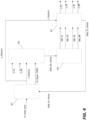
Fig. 6 is a flowchart of a method for applying braking force adjustments to the inside wheel first while applying braking forces while turning according to one embodiment. -
Fig. 1 illustrates an example of a vehicle system configured to apply braking forces using friction braking, regenerative braking, or a blended combination of friction and regenerative braking. A vehicle/system controller 101 includes anelectronic processor 103 and a non-transitory, computer-readable memory 105. Thememory 105 stores instructions that are accessed and executed by theelectronic processor 103 to cause thecontroller 101 to provide functionality including, for example, the functions described in the examples below. - The
controller 101 is communicatively coupled to a friction braking system including a front-left friction brake 107, a front-right friction brake 109, a rear-left friction brake 111, and a rear-right friction brake 113. In some implementations, the friction braking system includes a hydraulic pressure control system (not pictured) that is configured to adjust a braking force applied to each wheel of the vehicle by a respective one of thefriction brakes controller 101, as part of each individual friction brake, 107, 109, 111, 113, or as a separate component of the vehicle system. Furthermore, in some implementations, the system is configured to apply asymmetric braking such that under certain conditions a separate braking force can be determined for and applied to each individual wheel of the vehicle. Accordingly, under asymmetric braking, the braking force applied to the rear-right wheel by the rear-right friction brake 113 is not necessarily the same as the braking force applied to the rear-left wheel by the rear-left friction brake 111. Similarly, the braking force applied to the front-right wheel by the front-right friction brake 109 is not necessarily the same as the braking force applied to the front-left wheel by the front-left friction brake 107. - The
controller 101 is also communicatively coupled to a regenerative braking system that includes a front axleregenerative brake 115 and a rear axleregenerative brake 117. The regenerative braking system is configured to apply a braking force while generating electrical power that is then stored to a battery and/or provided to electrically-powered systems and components of the vehicle. Although the example ofFig. 1 shows both a front axleregenerative brake 115 and a rear axleregenerative brake 117, in some implementations, the system may include only a front axleregenerative brake 115 or only a rear axleregenerative brake 117 and not both. - The
controller 101 is also communicatively coupled to asteering wheel sensor 119 to receive a signal indicative of a desired steering and to abrake pedal sensor 121 to receive a signal indicative of a desired braking force. However, in other implementations, the signal indicative of a desired vehicle steering may come from other sources including, for example, another vehicle system (e.g., an automated driving/steering system), a steering control other than a "steering wheel" (e.g., a "joystick" control), or an adjusting steering compensation system that calculates a target vehicle steering based in part on a user control input. Similarly, in other implementations, the signal indicative of a desired braking force may come from other sources including, for example, another vehicle system (e.g., an automated driving or adaptive cruise control system). In still other implementations, a target steering and a target braking force can be calculated by thecontroller 101 based on inputs from one or more vehicles sensors or user input controls. - The
controller 101 is also communicatively coupled to ayaw rate sensor 123, a front side-slip angle sensor 125, and a rear side-slip angle sensor 127. Theyaw rate sensor 123 is configured to provide a signal indicative of a yaw rate of the vehicle (e.g., the rate at which the yaw of the vehicle is changing). The side-slip angle sensors Fig. 1 shows theyaw rate sensor 123 and the side-slip angle sensors controller 101 based, at least in part, on a measured yaw rate, a steering angle, and/or a lateral acceleration of the vehicle. Thecontroller 101 is also communicatively coupled to one or morelateral acceleration sensors 129. -
Figs. 2A, 2B, and 2C illustrates examples of different braking strategies applied to the front and rear axle of the vehicle using the system ofFig. 1 . InFig. 2A , a blended combination of a friction braking force (Fxfriction_FA) and a regenerative braking force (Fxregen) is applied to the wheels of thefront axle 201 while only a friction braking force (Fxfriction_RA) is applied to therear wheels 203. InFig. 2B , only friction braking forces are applied to both the front wheels (Fxfriction_FA) and the rear wheels (Fxfriction_RA). The same total braking force is applied to the vehicle in the example ofFig. 2A and in the example ofFig. 2B . However, because of the regenerative braking force (Fxregen) on the front axle in the example ofFig. 2A , the front axle will undergo greater braking force compared to the "friction only" braking in the example ofFig. 2B . Accordingly, the front axle will exhibit a greater side-slip angle on the front axle (α_F) with the blended braking ofFig. 2A as compared to the side-slip angle of the front axle (α_F) with the "friction only" braking ofFig. 2B . At the same time, the rear-axle will undergo a smaller braking force in the example ofFig. 2A causing the rear axle to have a smaller side-slip angle (α_R) in the example ofFig. 2A as compared to the side-slip angle of the rear axle (α_R) with the "friction only" braking ofFig. 2B . As a result, the vehicle steering performance tends to exhibit an "understeering" condition when blended friction/regenerative braking is applied to the front wheels while turning. Conversely, although not illustrated in the examples ofFigs. 2A and 2B , the vehicle steering performance tends to exhibit an "oversteering" condition when blended friction/regenerative braking is applied to the rear axle wheels (with friction only braking applied to the front axle wheels). - The example of
Fig. 2C illustrates a mechanism for adjusting the side-slip angles of the vehicle by applying additional side forces at the front axle (Fycompensate_FA) and at the rear axle (Fycompensate_RA). Applying these additional side forces to the front and rear axles in opposite directions results in a compensatory yaw moment applied to the vehicle. The compensatory yaw moment can be configured to compensate for the "understeering" condition illustrated in the example ofFig. 2A (and for the "oversteering" condition also discussed above). It can also be configured to regulate the side-slip angles on the front axle (α_F) and the rear axle (α_R) of the vehicle during regenerative braking to match the side-slip angles during the "friction only" braking so that the vehicle exhibits the same turning characteristics in either braking strategy. As illustrated in the example ofFig. 2C , the braking forces applied to the wheels of each axle are the same as in the example ofFig. 2A , but the side-slip angles are the same as in the example ofFig. 2B . - Because the additional side forces cannot be applied to each axle without some external input (i.e., another object or system applying the force to the vehicle), in some implementations, the side forces are realized in the form of a compensatory yaw moment that will have a similar effect on the operation of the vehicle. In some implementations, the compensatory yaw moment is generated by applying asymmetrical friction braking to the vehicle.
-
Fig. 3 illustrates a method for calculating and applying the additional side forces to achieve the compensatory yaw moment such as illustrated in the example ofFig. 2C . First, thecontroller 101 determines a target braking force (step 301) based, for example, on data received from thebrake pedal sensor 121. Thecontroller 101 then applies blended braking to the front axle wheels and friction only braking to the rear axle wheels based on the determined target braking force (step 303) and determines the actual side-slip angles on the front and rear axle wheels, respectively (step 305). Thecontroller 101 then determines an estimated side-slip angle for the front and rear axles based on the current steering and total braking force (step 307). The estimated side-slip angles for "friction only" braking can be determined, for example, by applying a vehicle modelling calculations or using a look-up table stored to thememory 105. Thecontroller 101 will then calculate a compensatory yaw moment that will cause the actual side-slip angles under blended braking to match the estimated side-slip angles for "friction only" braking (step 309). In some implementations, the compensatory yaw moment is determined by calculating an actual yaw moment resulting from the applied blended braking, determining an estimated yaw moment based on the estimated side-slip angles for the friction only braking, and determining a compensatory yaw moment based on the difference between the actual yaw moment and the estimated yaw moment. - Finally, the compensatory yaw moment is applied to the vehicle (step 311). In some implementations, the compensatory yaw moment is applied by controlling the torque or braking force on the wheels on the vehicle. In some implementations, the
controller 101 is configured to apply the compensatory yaw moment by applying asymmetric friction braking forces on the vehicle. For example, the compensatory yaw moment can be applied by increasing the braking force on the rear-left wheel and increasing the braking force on the front-right wheel of the vehicle. In some implementations, the braking forces of the wheels on the same axle are correspondingly adjusted to ensure that the same total braking force is applied. For example, thecontroller 101 may be configured to apply a compensatory yaw moment by increasing the braking force applied by the rear-right friction brake 113 and decreasing the braking force applied by the rear-leftfriction brake 111 while also increasing the braking force applied by the front-leftfriction brake 107 and decreasing the braking force applied by the front-right friction brake 109. -
Fig. 4 illustrates another example of how thecontroller 101 might be configured to apply the compensatory yaw moment through asymmetric control of the friction brakes. First, thecontroller 101 performs abraking force adaptation 401 by calculating a hydraulic pressure for friction braking (p_Hydraulic) and a regenerative braking force for the driven axle (Fb_Regen_FA for front axle regenerative braking or Fb_Regen_RA for rear axle regenerative braking) based on a driver requested total braking force (Fx_target_driver). Thecontroller 101 then performs a yaw torque calculation usingtire modeling 403 to determine a compensatory vehicle yaw moment (Delta_Mz_Vehicle) based on the hydraulic pressure for friction braking (p_Hydraulic), the regenerative braking force (Fb_Regen_FA/RA), the side-slip angle of the front axle wheels (α_FA), and the side-slip angle of the rear axle wheels (α_RA). Thecontroller 101 then performs wheel brakingtorque arbitration 405 to determine an adjustment of the braking force to be applied to each of the four friction brakes (dMb_FL (front-left), dMb_FR (front-right), dMb_RL (rear-left), and dMb_RR (rear-right)) that will achieve the calculated compensatory yaw moment (Delta_Mz_Vehicle). Finally, actually wheelpressure calculation 407 is performed to calculate an actual hydraulic pressure that will be applied to each of the friction brakes (p_FL (front-left pressure), p_FR (front-right pressure), p_RL (rear-left pressure), and p_RR (rear-right pressure)) based on the total hydraulic pressure demand (p_Hydraulic) and the calculated friction braking adjustments for each wheel. In this example, additional friction braking force is applied to each wheel to apply the compensatory yaw moment. Accordingly, the additional overall braking force introduced by the brake control (Delta_Fb_Vehicle) is used as feedback and is compensated when recalculating the requested overall braking force. - In the examples discussed above, the actual side-slip angles (α_F and α_R) that occur under blended braking are measured/calculated and compared to estimated side-slip angles that would occur under "friction only" braking. However, in some implementations, the
controller 101 may be configured to calculate/determine estimated side-slip angle values for both blended braking and "friction only" braking based on the desired steering input and the desired braking inputs. Furthermore, in some implementations, thecontroller 101 might be configured to monitor the actual side-slip angles of the vehicle and to gradually adjust the applied compensatory yaw moment until the actual-side-slip angles of the vehicle approach target side-slip angles. - As noted above, in some implementations, the estimated side-slip angles for "friction only" braking are calculated in real-time using modelling algorithms based on vehicle dynamics while, in other implementations, the estimated side-slip angles for "friction only" braking are determined using a "look-up table" stored to the
memory 105. The look-up table may be configured to identify a set of side-slip angles corresponding to each combination of vehicle performance variables including, for example, target steering, current yaw rate, total braking force, and lateral acceleration. In some implementations, this look-up table is compiled by experimental data and/or modelling calculations. However, in other implementations, the look-up table is updated and refined during operation of the vehicle based on observed actual side-slip angles under various performance conditions while using "friction only" braking. - In some implementations, additional control mechanisms are implemented to achieve target braking performance and vehicle dynamics. As illustrated in the example of
Fig. 5 , acontroller 101 may be configured to calculate/monitor lateral acceleration of a vehicle (step 501) and to compare the lateral acceleration to a threshold (step 503). If the lateral acceleration is below the threshold, blended braking is applied with full, unrestricted regenerative braking (step 505). However, under conditions where excessively high lateral acceleration is detected (i.e., lateral acceleration above a threshold), thecontroller 101 may limit the regenerative braking (step 507). For example, thecontroller 101 may be configured to used "friction only" braking when it detects that lateral acceleration is above a defined threshold. Alternatively, thecontroller 101 may be configured to adjust the amount of braking force applied by the regenerative braking based, at least in part, on the detected lateral acceleration (e.g., when the lateral acceleration is above the threshold, the braking force applied by regenerative braking is decreased by a percentage in proportion to the amount by which the lateral acceleration exceeds the threshold). - In some implementations, the
controller 101 is configured to apply a braking strategy where inside wheels are braked before outside wheels. For example, in the method ofFig. 6 , thecontroller 101 monitors lateral acceleration of the vehicle (step 601) and detects any changes in the turning of the vehicle (step 603) (e.g., based on a change in the steering wheel angle or a change in the vehicle yaw or yaw rate). In response to detecting a change in the turning of the vehicle (step 603), thecontroller 101 determines a target braking adjustment (step 605) and first applies the target braking adjustment to the inside wheels (step 607). Later, the braking adjustment is also applied to the outside wheels (step 609). - Accordingly, in the method of
Fig. 6 , the braking strategy is adjusted to initially favor the inside wheels in response to detecting a change in vehicle turning. However, the method ofFig. 6 also adjusts the braking strategy to initially favor the inside wheels (e.g., apply a greater braking force to the inside wheels first) in response to detecting a change in braking demand while the vehicle is turning. Thecontroller 101 monitors the target braking (e.g., braking force demand) (step 611) and detects any changes in the braking force demand (step 613). If the vehicle is not turning (step 615), thecontroller 101 responds to the detected change in the braking force demand by calculating an adjustment to the target braking strategy (step 617) and applies the updated target braking strategy to all wheels of the vehicle (step 619). However, if thecontroller 101 determines that the vehicle is turning (step 615), then the control determines the target braking adjustment (step 605) and applies the target braking adjustment to the "inside wheels" first (step 607) before applying the braking adjustment to the outside wheels (step 609). - In some implementations, the
controller 101 may be configured to apply braking to the inside wheels first under all conditions or, in some implementations, may be configured to only apply the "inside first" braking control strategy under certain detected performance and operating conditions (e.g., when vehicle speed exceeds a threshold). Similarly, in some implementations, thecontroller 101 may be configured to adjust the rate at which the braking force of the "inside wheels" based on certain performance/operating conditions. For example, thecontroller 101 may be configured to use a "torque vectoring" strategy wherein a certain percentage of the total braking force for the rear axle wheels is applied by the "inside wheel" and is gradually adjusted to apply a greater percentage of the total braking force on the "outside wheel." Furthermore, in some implementations, thecontroller 101 is configured to use a "feed-forward" control strategy to reduce the amount of friction energy used to mitigate the understeering condition. - Thus, the invention provides, among other things, a system and method for controlling friction braking and blended regenerative/friction braking to mitigate understeering and oversteering conditions and to cause vehicle performance under blended braking to match performance under friction only braking. Various features and advantages of the invention are set forth in the following claims.
Claims (15)
- A method of controlling a vehicle braking system, the method comprising:applying a braking force to a vehicle by applying a regenerative braking force to wheels of a first axle of the vehicle and applying a friction braking force to wheels of a second axle of the vehicle;determining, by an electronic processor (103), a set of actual side-slip angles for the vehicle, the set of actual side-slip angles including a first axle side-slip angle for the wheels of the first axle and a second axle side-slip angle for the wheels of the second axle wherein determining the set of actual side-slip angles includes receiving, by the electronic processor (103), a first signal from a first side-slip angle sensor (125, 127) indicative of the first side-slip angle of the wheels of the first axle and a second signal from a second side-slip angle sensor (125, 127) indicative of the second side-slip angle of the wheels of the second axle;determining, by the electronic processor (103), a set of estimated side-slip angles for the vehicle, the set of estimated side-slip angles including an estimated first axle side-slip angle for the wheels of the first axle and an estimate second axle side-slip angle for the wheels of the second axle, the set of estimated side-slip angles being indicative of side-slip angles for the vehicle estimated to occur under current driving conditions if the braking force were applied to the vehicle using only friction braking;determining a compensatory yaw moment for the vehicle based on a difference between the set of actual side-slip angles and the set of estimated side-slip angles; andapplying the compensatory yaw moment to the vehicle to cause the set of actual side-slip angles to approach the set of estimated side-slip angles.
- The method of claim 1, wherein applying the compensatory yaw moment to the vehicle includes applying asymmetric friction braking to the wheels of the vehicle.
- The method of claim 1, wherein applying the braking force to the vehicle includes applying a blended braking force to the wheels of the first axle by applying the regenerative braking force to the wheels of the first axle and applying a friction braking force to the wheels of the first axle.
- The method of claim 1, wherein determining the set of estimated side-slip angles includes applying vehicle modeling to determine the set of estimated side-slip angles based on one or more performance variables selected from a group consisting of lateral acceleration, vehicle steering, vehicle speed, and total braking force.
- The method of claim 1, wherein determining the set of estimated side-slip angles includes determining the set of estimated side-slip angles using a look-up table stored to a non-transitory computer-readable memory (105).
- The method of claim 1, wherein determining the compensatory yaw moment for the vehicle includes:determining an actual yaw moment for the vehicle;determining an estimated yaw moment for the vehicle based on the set of estimated side-slip angles; andcalculating the compensatory yaw moment as a difference between the actual yaw moment and the estimated yaw moment.
- The method of claim 1, wherein applying the braking force to the vehicle includesdetermining a target braking force;identifying a set of inside wheels of a vehicle, wherein the inside wheels include the wheels on a side of the vehicle in a direction of lateral acceleration; andapplying the target braking force to the inside wheels before applying the target braking force to other wheels of the vehicle.
- A vehicle braking system comprising an electronic controller (101) configured to:apply a braking force to a vehicle by applying a regenerative braking force to wheels of a first axle of the vehicle and applying a friction braking force to wheels of a second axle of the vehicle;determine a set of actual side-slip angles for the vehicle, the set of actual side-slip angles including a first axle side-slip angle for the wheels of the first axle and a second axle side-slip angle for the wheels of the second axle, wherein the set of actual side-slip angles is determined by receiving a first signal from a first side-slip angle sensor (125, 127) indicative of the first side-slip angle of the wheels of the first axle and a second signal from a second side-slip angle sensor (125, 127) indicative of the second side-slip angle of the wheels of the second axle;determine a set of estimated side-slip angles for the vehicle, the set of estimated side-slip angles including an estimated first axle side-slip angle for the wheels of the first axle and an estimate second axle side-slip angle for the wheels of the second axle, the set of estimated side-slip angles being indicative of side-slip angles for the vehicle estimated to occur under current driving conditions if the braking force were applied to the vehicle using only friction braking;determine a compensatory yaw moment for the vehicle based on a difference between the set of actual side-slip angles and the set of estimated side-slip angles; andapply the compensatory yaw moment to the vehicle to cause the set of actual side-slip angles to approach the set of estimated side-slip angles.
- The vehicle braking system of claim 8, wherein the electronic controller (101) is configured to apply the compensatory yaw moment to the vehicle by applying asymmetric friction braking to the wheels of the vehicle.
- The vehicle braking system of claim 8, wherein the electronic controller (101) is configured to apply the braking force to the vehicle by applying a blended braking force to the wheels of the first axle by applying the regenerative braking force to the wheels of the first axle and applying a friction braking force to the wheels of the first axle.
- The vehicle braking system of claim 8, wherein the electronic controller (101) is configured to determine the set of estimated side-slip angles by applying vehicle modeling to determine the set of estimated side-slip angles based on one or more performance variables selected from a group consisting of lateral acceleration, vehicle steering, vehicle speed, and total braking force.
- The vehicle braking system of claim 8, wherein the electronic controller (101) is configured to determine the set of estimated side-slip angles by determining the set of estimated side-slip angles using a look-up table stored to a non-transitory computer-readable memory (105).
- The vehicle braking system of claim 8, wherein the electronic controller (101) is configured to determine the compensatory yaw moment for the vehicle by:determining an actual yaw moment for the vehicle;determining an estimated yaw moment for the vehicle based on the set of estimated side-slip angles; andcalculating the compensatory yaw moment as a difference between the actual yaw moment and the estimated yaw moment.
- The vehicle braking system of claim 8, wherein the electronic controller (101) is configured to apply the braking force to the vehicle bydetermining a target braking force;identifying a set of inside wheels of a vehicle, wherein the inside wheels include the wheels on a side of the vehicle in a direction of lateral acceleration; andapplying the target braking force to the inside wheels before applying the target braking force to other wheels of the vehicle.
- A vehicle braking system comprising:a hydraulic braking system including a plurality of friction brakes (107, 109, 111, 113) includinga front-right wheel friction brake (109),a front-left wheel friction brake (107),a rear-right wheel friction brake (113), anda rear-left wheel friction brake (111),wherein the hydraulic braking system is configured to apply friction braking to the wheels of the vehicle by adjusting a hydraulic pressure to each friction brake;a regenerative braking system including a regenerative braking motor configured to apply a braking force to the wheels of a first axle while generating electrical power; anda braking system controller (101) configured toreceive a signal indicative of a target total braking force for the vehicle,operating the friction braking system to apply a first axle friction braking force to the wheels of the first axle and to apply a second axle friction braking force to the wheels of the second axle,operating the regenerative braking system to apply a regenerative braking force to the wheels of the first axle,determine a set of actual blended braking side-slip angles for the vehicle by receiving a first signal from a first side-slip angle sensor (125, 127) indicative of the first side-slip angle of the wheels of the first axle and a second signal from a second side-slip angle sensor (125, 127) indicative of the second side-slip angle of the wheels of the second axle,determine a set of estimated friction only braking side-slip angles for the vehicle based on vehicle modeling, wherein the set of estimated friction only braking side-slip angles for the vehicle is indicative of side-slip angles for the vehicle estimated to occur based on the vehicle modeling under current driving condition if the total braking force were applied to the vehicle using only the friction braking system,determine a compensatory yaw moment for the vehicle based on a difference between the set of actual blended braking side-slip angles and the set of estimated friction only braking side-slip angles, andapply the compensatory yaw moment to the vehicle by adjusting the operation of the friction braking system to apply asymmetric braking force to the wheels.
Applications Claiming Priority (2)
| Application Number | Priority Date | Filing Date | Title |
|---|---|---|---|
| US201662410036P | 2016-10-19 | 2016-10-19 | |
| PCT/EP2017/075380 WO2018073017A1 (en) | 2016-10-19 | 2017-10-05 | Lateral dynamic control for regenerative and friction brake blending |
Publications (2)
| Publication Number | Publication Date |
|---|---|
| EP3529113A1 EP3529113A1 (en) | 2019-08-28 |
| EP3529113B1 true EP3529113B1 (en) | 2023-03-08 |
Family
ID=60120033
Family Applications (1)
| Application Number | Title | Priority Date | Filing Date |
|---|---|---|---|
| EP17784924.7A Active EP3529113B1 (en) | 2016-10-19 | 2017-10-05 | Lateral dynamic control for regenerative and friction brake blending |
Country Status (6)
| Country | Link |
|---|---|
| US (1) | US11427172B2 (en) |
| EP (1) | EP3529113B1 (en) |
| JP (1) | JP6872607B2 (en) |
| KR (1) | KR102416064B1 (en) |
| CN (1) | CN109982902B (en) |
| WO (1) | WO2018073017A1 (en) |
Families Citing this family (6)
| Publication number | Priority date | Publication date | Assignee | Title |
|---|---|---|---|---|
| JP6830882B2 (en) * | 2017-10-20 | 2021-02-17 | 株式会社シマノ | Brake control and brake system |
| DE102019217610A1 (en) * | 2019-11-14 | 2021-05-20 | Volkswagen Aktiengesellschaft | Method for operating a combination consisting of a towing vehicle and at least one trailer |
| JP7561054B2 (en) * | 2021-02-15 | 2024-10-03 | 株式会社Subaru | Vehicle control device |
| US11713036B2 (en) * | 2021-10-27 | 2023-08-01 | GM Global Technology Operations LLC | System and method for maintaining stability of a motor vehicle |
| WO2024007265A1 (en) * | 2022-07-07 | 2024-01-11 | 华为技术有限公司 | Braking method and apparatus for vehicle |
| DE102022131330A1 (en) | 2022-11-28 | 2024-05-29 | Schaeffler Technologies AG & Co. KG | Braking system for a motor vehicle driven by an electric machine |
Family Cites Families (43)
| Publication number | Priority date | Publication date | Assignee | Title |
|---|---|---|---|---|
| DE3840456A1 (en) * | 1988-12-01 | 1990-06-07 | Bosch Gmbh Robert | METHOD FOR INCREASING THE CONTROL OF A VEHICLE |
| JP2762711B2 (en) * | 1990-07-02 | 1998-06-04 | 日産自動車株式会社 | Vehicle braking behavior compensator |
| JPH06341822A (en) * | 1993-06-02 | 1994-12-13 | Nissan Motor Co Ltd | Measuring apparatus for tire slip angle |
| US5735584A (en) * | 1994-11-25 | 1998-04-07 | Itt Automotive Europe Gmbh | Process for driving stability control with control via pressure gradients |
| JPH08183433A (en) * | 1995-01-05 | 1996-07-16 | Nissan Motor Co Ltd | Slip angle measuring device using the Doppler effect |
| JPH08183434A (en) * | 1995-01-05 | 1996-07-16 | Nissan Motor Co Ltd | Slip angle measuring device using the Doppler effect |
| US6547343B1 (en) * | 1997-09-08 | 2003-04-15 | General Motors Corporation | Brake system control |
| US6035251A (en) * | 1997-11-10 | 2000-03-07 | General Motors Corporation | Brake system control method employing yaw rate and ship angle control |
| US6195606B1 (en) * | 1998-12-07 | 2001-02-27 | General Motors Corporation | Vehicle active brake control with bank angle compensation |
| JP3623456B2 (en) * | 2001-02-28 | 2005-02-23 | トヨタ自動車株式会社 | Vehicle travel control device |
| US6549842B1 (en) * | 2001-10-31 | 2003-04-15 | Delphi Technologies, Inc. | Method and apparatus for determining an individual wheel surface coefficient of adhesion |
| US6466857B1 (en) * | 2001-12-05 | 2002-10-15 | Delphi Technologies, Inc. | Drive wheel traction control during vehicle stability enhancement events |
| US20030230933A1 (en) * | 2002-06-17 | 2003-12-18 | Ford Motor Company | Control of regenerative braking during a yaw stability control event |
| US7104617B2 (en) * | 2002-09-06 | 2006-09-12 | Ford Motor Company | Independent braking and controllability control method and system for a vehicle with regenerative braking |
| US6691013B1 (en) * | 2002-09-06 | 2004-02-10 | Ford Motor Company | Braking and controllability control method and system for a vehicle with regenerative braking |
| US6885931B2 (en) * | 2003-04-24 | 2005-04-26 | Visteon Global Technologies, Inc. | Control algorithm for a yaw stability management system |
| US7409280B2 (en) * | 2004-01-15 | 2008-08-05 | Nissan Motor Co., Ltd. | Vehicle braking control apparatus |
| US6959970B2 (en) * | 2004-03-18 | 2005-11-01 | Ford Global Technologies, Llc | Method and apparatus for controlling a trailer and an automotive vehicle with a yaw stability control system |
| WO2005110827A1 (en) * | 2004-05-03 | 2005-11-24 | Continental Teves Ag & Co. Ohg | Method for controlling a brake system of a motor vehicle |
| US8152245B2 (en) * | 2004-09-09 | 2012-04-10 | Kelsey-Hayes Company | Vehicle system having regenerative brake control |
| US20090055040A1 (en) * | 2005-03-24 | 2009-02-26 | Kabushiki Kaisha Bridgestone | Method for estimating tire slip angle and a tire with sensors mounted therein |
| JP5381203B2 (en) | 2008-03-31 | 2014-01-08 | 株式会社アドヴィックス | Vehicle motion control device |
| EP2172378B1 (en) * | 2008-10-06 | 2019-07-03 | Volvo Car Corporation | A method and device for regenerative braking in a vehicle |
| GB2480852A (en) * | 2010-06-03 | 2011-12-07 | Mira Ltd | Yaw motion control of a vehicle |
| US8521349B2 (en) * | 2010-06-10 | 2013-08-27 | Ford Global Technologies | Vehicle steerability and stability control via independent wheel torque control |
| US8998353B2 (en) * | 2010-09-07 | 2015-04-07 | GM Global Technology Operations LLC | Hybrid brake control |
| US9283936B2 (en) * | 2011-08-29 | 2016-03-15 | Toyota Jidosha Kabushiki Kaisha | Braking force control apparatus for vehicle |
| JP5988560B2 (en) * | 2011-09-27 | 2016-09-07 | 本田技研工業株式会社 | Car body behavior stabilization device |
| JP5879143B2 (en) * | 2012-02-09 | 2016-03-08 | 日立オートモティブシステムズ株式会社 | Vehicle motion control device and vehicle motion control method |
| JP5919889B2 (en) * | 2012-03-01 | 2016-05-18 | 株式会社ジェイテクト | Vehicle attitude control device |
| CA2879295C (en) * | 2012-07-19 | 2017-03-14 | Honda Motor Co. Ltd. | Vehicle brake force generation device |
| JP6267485B2 (en) * | 2013-10-30 | 2018-01-24 | 株式会社Subaru | Control device for four-wheel drive hybrid vehicle |
| US9096226B2 (en) * | 2013-10-31 | 2015-08-04 | Ford Global Technologies, Llc | Vehicle dynamic controls coordination system for dual-axle driven electric vehicles |
| JP6418373B2 (en) * | 2014-04-04 | 2018-11-07 | 日立オートモティブシステムズ株式会社 | Vehicle control apparatus and vehicle control method |
| KR20170072935A (en) * | 2014-12-16 | 2017-06-27 | 비와이디 컴퍼니 리미티드 | Electric vehicle, active safety control system of electric vehicle, and control method therefor |
| US9637004B2 (en) * | 2015-06-18 | 2017-05-02 | E-Aam Driveline Systems Ab | System and method for delimiting regenerative braking |
| CN106467111B (en) * | 2015-08-20 | 2019-06-07 | 比亚迪股份有限公司 | Vehicle body stable control method, system and automobile |
| CN106608201B (en) * | 2015-10-26 | 2019-04-19 | 比亚迪股份有限公司 | Electric vehicle and active safety control system and method therefor |
| JP6547780B2 (en) * | 2017-02-16 | 2019-07-24 | トヨタ自動車株式会社 | Vehicle turning control device |
| GB2560914B (en) * | 2017-03-27 | 2022-05-04 | Arrival Ltd | Method and apparatus for controlling a vehicle |
| JP6952014B2 (en) * | 2018-06-13 | 2021-10-20 | 日立Astemo株式会社 | Vehicle control device, vehicle control method, and vehicle control system |
| JP6734905B2 (en) * | 2018-11-07 | 2020-08-05 | 本田技研工業株式会社 | Vehicle behavior stabilization device |
| KR20210147154A (en) * | 2020-05-27 | 2021-12-07 | 현대자동차주식회사 | Integrated control apparatus of a vehicle, system having the same and method thereof |
-
2017
- 2017-10-05 EP EP17784924.7A patent/EP3529113B1/en active Active
- 2017-10-05 CN CN201780064541.2A patent/CN109982902B/en active Active
- 2017-10-05 KR KR1020197011181A patent/KR102416064B1/en active Active
- 2017-10-05 WO PCT/EP2017/075380 patent/WO2018073017A1/en not_active Ceased
- 2017-10-05 JP JP2019518983A patent/JP6872607B2/en active Active
- 2017-10-05 US US16/339,021 patent/US11427172B2/en active Active
Also Published As
| Publication number | Publication date |
|---|---|
| JP2019536678A (en) | 2019-12-19 |
| KR20190069431A (en) | 2019-06-19 |
| JP6872607B2 (en) | 2021-05-19 |
| CN109982902B (en) | 2021-08-31 |
| US20190225199A1 (en) | 2019-07-25 |
| EP3529113A1 (en) | 2019-08-28 |
| KR102416064B1 (en) | 2022-07-04 |
| US11427172B2 (en) | 2022-08-30 |
| WO2018073017A1 (en) | 2018-04-26 |
| CN109982902A (en) | 2019-07-05 |
Similar Documents
| Publication | Publication Date | Title |
|---|---|---|
| EP3529113B1 (en) | Lateral dynamic control for regenerative and friction brake blending | |
| US8694208B2 (en) | Vehicle behavior control apparatus | |
| KR101697809B1 (en) | Method and braking system for influencing driving dynamics by means of braking and driving operations | |
| JP6844500B2 (en) | Vehicle behavior control device | |
| US11161499B2 (en) | Vehicle driving assistance device | |
| US20100191423A1 (en) | Vehicle rollover prevention control apparatus and vehicle rollover prevention control method | |
| US11745706B2 (en) | Vehicle motion control device, vehicle motion control method, and vehicle motion control system | |
| US9895978B2 (en) | Braking force control method for vehicle | |
| JP2018093645A (en) | Device for controlling electric vehicle, system for controlling electric vehicle and method for controlling electric vehicle | |
| KR102805124B1 (en) | Wheel slip control method for vehicle | |
| WO2018105435A1 (en) | Control device for electric vehicle, control system for electric vehicle, and control method for electric vehicle | |
| KR102881929B1 (en) | Electronic stability control method for vehicle | |
| US20150274033A1 (en) | Wheel control device, vehicle, and wheel control method | |
| US8600639B2 (en) | Yaw rate control with simultaneous maximum deceleration | |
| JP2012035698A (en) | Brake control apparatus of vehicle | |
| EP2289746B1 (en) | System for enhancing cornering performance of a vehicle controlled by a safety system | |
| JP4765552B2 (en) | Driving force control device for electric vehicle | |
| WO2024048322A1 (en) | Vehicle control device, vehicle control method, and vehicle control system | |
| JP7103080B2 (en) | Vehicle control device |
Legal Events
| Date | Code | Title | Description |
|---|---|---|---|
| STAA | Information on the status of an ep patent application or granted ep patent |
Free format text: STATUS: UNKNOWN |
|
| STAA | Information on the status of an ep patent application or granted ep patent |
Free format text: STATUS: THE INTERNATIONAL PUBLICATION HAS BEEN MADE |
|
| PUAI | Public reference made under article 153(3) epc to a published international application that has entered the european phase |
Free format text: ORIGINAL CODE: 0009012 |
|
| STAA | Information on the status of an ep patent application or granted ep patent |
Free format text: STATUS: REQUEST FOR EXAMINATION WAS MADE |
|
| 17P | Request for examination filed |
Effective date: 20190520 |
|
| AK | Designated contracting states |
Kind code of ref document: A1 Designated state(s): AL AT BE BG CH CY CZ DE DK EE ES FI FR GB GR HR HU IE IS IT LI LT LU LV MC MK MT NL NO PL PT RO RS SE SI SK SM TR |
|
| AX | Request for extension of the european patent |
Extension state: BA ME |
|
| DAV | Request for validation of the european patent (deleted) | ||
| DAX | Request for extension of the european patent (deleted) | ||
| RAP1 | Party data changed (applicant data changed or rights of an application transferred) |
Owner name: ROBERT BOSCH GMBH |
|
| STAA | Information on the status of an ep patent application or granted ep patent |
Free format text: STATUS: EXAMINATION IS IN PROGRESS |
|
| 17Q | First examination report despatched |
Effective date: 20211216 |
|
| GRAP | Despatch of communication of intention to grant a patent |
Free format text: ORIGINAL CODE: EPIDOSNIGR1 |
|
| STAA | Information on the status of an ep patent application or granted ep patent |
Free format text: STATUS: GRANT OF PATENT IS INTENDED |
|
| INTG | Intention to grant announced |
Effective date: 20221118 |
|
| GRAS | Grant fee paid |
Free format text: ORIGINAL CODE: EPIDOSNIGR3 |
|
| GRAA | (expected) grant |
Free format text: ORIGINAL CODE: 0009210 |
|
| STAA | Information on the status of an ep patent application or granted ep patent |
Free format text: STATUS: THE PATENT HAS BEEN GRANTED |
|
| AK | Designated contracting states |
Kind code of ref document: B1 Designated state(s): AL AT BE BG CH CY CZ DE DK EE ES FI FR GB GR HR HU IE IS IT LI LT LU LV MC MK MT NL NO PL PT RO RS SE SI SK SM TR |
|
| REG | Reference to a national code |
Ref country code: GB Ref legal event code: FG4D |
|
| REG | Reference to a national code |
Ref country code: CH Ref legal event code: EP Ref country code: AT Ref legal event code: REF Ref document number: 1552396 Country of ref document: AT Kind code of ref document: T Effective date: 20230315 |
|
| REG | Reference to a national code |
Ref country code: DE Ref legal event code: R096 Ref document number: 602017066657 Country of ref document: DE |
|
| REG | Reference to a national code |
Ref country code: IE Ref legal event code: FG4D |
|
| REG | Reference to a national code |
Ref country code: LT Ref legal event code: MG9D |
|
| REG | Reference to a national code |
Ref country code: NL Ref legal event code: MP Effective date: 20230308 |
|
| PG25 | Lapsed in a contracting state [announced via postgrant information from national office to epo] |
Ref country code: RS Free format text: LAPSE BECAUSE OF FAILURE TO SUBMIT A TRANSLATION OF THE DESCRIPTION OR TO PAY THE FEE WITHIN THE PRESCRIBED TIME-LIMIT Effective date: 20230308 Ref country code: NO Free format text: LAPSE BECAUSE OF FAILURE TO SUBMIT A TRANSLATION OF THE DESCRIPTION OR TO PAY THE FEE WITHIN THE PRESCRIBED TIME-LIMIT Effective date: 20230608 Ref country code: LV Free format text: LAPSE BECAUSE OF FAILURE TO SUBMIT A TRANSLATION OF THE DESCRIPTION OR TO PAY THE FEE WITHIN THE PRESCRIBED TIME-LIMIT Effective date: 20230308 Ref country code: LT Free format text: LAPSE BECAUSE OF FAILURE TO SUBMIT A TRANSLATION OF THE DESCRIPTION OR TO PAY THE FEE WITHIN THE PRESCRIBED TIME-LIMIT Effective date: 20230308 Ref country code: HR Free format text: LAPSE BECAUSE OF FAILURE TO SUBMIT A TRANSLATION OF THE DESCRIPTION OR TO PAY THE FEE WITHIN THE PRESCRIBED TIME-LIMIT Effective date: 20230308 Ref country code: ES Free format text: LAPSE BECAUSE OF FAILURE TO SUBMIT A TRANSLATION OF THE DESCRIPTION OR TO PAY THE FEE WITHIN THE PRESCRIBED TIME-LIMIT Effective date: 20230308 |
|
| REG | Reference to a national code |
Ref country code: AT Ref legal event code: MK05 Ref document number: 1552396 Country of ref document: AT Kind code of ref document: T Effective date: 20230308 |
|
| PG25 | Lapsed in a contracting state [announced via postgrant information from national office to epo] |
Ref country code: SE Free format text: LAPSE BECAUSE OF FAILURE TO SUBMIT A TRANSLATION OF THE DESCRIPTION OR TO PAY THE FEE WITHIN THE PRESCRIBED TIME-LIMIT Effective date: 20230308 Ref country code: NL Free format text: LAPSE BECAUSE OF FAILURE TO SUBMIT A TRANSLATION OF THE DESCRIPTION OR TO PAY THE FEE WITHIN THE PRESCRIBED TIME-LIMIT Effective date: 20230308 Ref country code: GR Free format text: LAPSE BECAUSE OF FAILURE TO SUBMIT A TRANSLATION OF THE DESCRIPTION OR TO PAY THE FEE WITHIN THE PRESCRIBED TIME-LIMIT Effective date: 20230609 Ref country code: FI Free format text: LAPSE BECAUSE OF FAILURE TO SUBMIT A TRANSLATION OF THE DESCRIPTION OR TO PAY THE FEE WITHIN THE PRESCRIBED TIME-LIMIT Effective date: 20230308 |
|
| PG25 | Lapsed in a contracting state [announced via postgrant information from national office to epo] |
Ref country code: SM Free format text: LAPSE BECAUSE OF FAILURE TO SUBMIT A TRANSLATION OF THE DESCRIPTION OR TO PAY THE FEE WITHIN THE PRESCRIBED TIME-LIMIT Effective date: 20230308 Ref country code: RO Free format text: LAPSE BECAUSE OF FAILURE TO SUBMIT A TRANSLATION OF THE DESCRIPTION OR TO PAY THE FEE WITHIN THE PRESCRIBED TIME-LIMIT Effective date: 20230308 Ref country code: PT Free format text: LAPSE BECAUSE OF FAILURE TO SUBMIT A TRANSLATION OF THE DESCRIPTION OR TO PAY THE FEE WITHIN THE PRESCRIBED TIME-LIMIT Effective date: 20230710 Ref country code: EE Free format text: LAPSE BECAUSE OF FAILURE TO SUBMIT A TRANSLATION OF THE DESCRIPTION OR TO PAY THE FEE WITHIN THE PRESCRIBED TIME-LIMIT Effective date: 20230308 Ref country code: CZ Free format text: LAPSE BECAUSE OF FAILURE TO SUBMIT A TRANSLATION OF THE DESCRIPTION OR TO PAY THE FEE WITHIN THE PRESCRIBED TIME-LIMIT Effective date: 20230308 Ref country code: AT Free format text: LAPSE BECAUSE OF FAILURE TO SUBMIT A TRANSLATION OF THE DESCRIPTION OR TO PAY THE FEE WITHIN THE PRESCRIBED TIME-LIMIT Effective date: 20230308 |
|
| PG25 | Lapsed in a contracting state [announced via postgrant information from national office to epo] |
Ref country code: SK Free format text: LAPSE BECAUSE OF FAILURE TO SUBMIT A TRANSLATION OF THE DESCRIPTION OR TO PAY THE FEE WITHIN THE PRESCRIBED TIME-LIMIT Effective date: 20230308 Ref country code: PL Free format text: LAPSE BECAUSE OF FAILURE TO SUBMIT A TRANSLATION OF THE DESCRIPTION OR TO PAY THE FEE WITHIN THE PRESCRIBED TIME-LIMIT Effective date: 20230308 Ref country code: IS Free format text: LAPSE BECAUSE OF FAILURE TO SUBMIT A TRANSLATION OF THE DESCRIPTION OR TO PAY THE FEE WITHIN THE PRESCRIBED TIME-LIMIT Effective date: 20230708 |
|
| REG | Reference to a national code |
Ref country code: DE Ref legal event code: R097 Ref document number: 602017066657 Country of ref document: DE |
|
| PLBE | No opposition filed within time limit |
Free format text: ORIGINAL CODE: 0009261 |
|
| STAA | Information on the status of an ep patent application or granted ep patent |
Free format text: STATUS: NO OPPOSITION FILED WITHIN TIME LIMIT |
|
| PG25 | Lapsed in a contracting state [announced via postgrant information from national office to epo] |
Ref country code: SI Free format text: LAPSE BECAUSE OF FAILURE TO SUBMIT A TRANSLATION OF THE DESCRIPTION OR TO PAY THE FEE WITHIN THE PRESCRIBED TIME-LIMIT Effective date: 20230308 Ref country code: DK Free format text: LAPSE BECAUSE OF FAILURE TO SUBMIT A TRANSLATION OF THE DESCRIPTION OR TO PAY THE FEE WITHIN THE PRESCRIBED TIME-LIMIT Effective date: 20230308 |
|
| 26N | No opposition filed |
Effective date: 20231211 |
|
| PG25 | Lapsed in a contracting state [announced via postgrant information from national office to epo] |
Ref country code: IT Free format text: LAPSE BECAUSE OF FAILURE TO SUBMIT A TRANSLATION OF THE DESCRIPTION OR TO PAY THE FEE WITHIN THE PRESCRIBED TIME-LIMIT Effective date: 20230308 Ref country code: MC Free format text: LAPSE BECAUSE OF FAILURE TO SUBMIT A TRANSLATION OF THE DESCRIPTION OR TO PAY THE FEE WITHIN THE PRESCRIBED TIME-LIMIT Effective date: 20230308 |
|
| REG | Reference to a national code |
Ref country code: CH Ref legal event code: PL |
|
| REG | Reference to a national code |
Ref country code: BE Ref legal event code: MM Effective date: 20231031 |
|
| PG25 | Lapsed in a contracting state [announced via postgrant information from national office to epo] |
Ref country code: LU Free format text: LAPSE BECAUSE OF NON-PAYMENT OF DUE FEES Effective date: 20231005 |
|
| PG25 | Lapsed in a contracting state [announced via postgrant information from national office to epo] |
Ref country code: LU Free format text: LAPSE BECAUSE OF NON-PAYMENT OF DUE FEES Effective date: 20231005 |
|
| PG25 | Lapsed in a contracting state [announced via postgrant information from national office to epo] |
Ref country code: CH Free format text: LAPSE BECAUSE OF NON-PAYMENT OF DUE FEES Effective date: 20231031 |
|
| PG25 | Lapsed in a contracting state [announced via postgrant information from national office to epo] |
Ref country code: CH Free format text: LAPSE BECAUSE OF NON-PAYMENT OF DUE FEES Effective date: 20231031 |
|
| PG25 | Lapsed in a contracting state [announced via postgrant information from national office to epo] |
Ref country code: BE Free format text: LAPSE BECAUSE OF NON-PAYMENT OF DUE FEES Effective date: 20231031 |
|
| PG25 | Lapsed in a contracting state [announced via postgrant information from national office to epo] |
Ref country code: IE Free format text: LAPSE BECAUSE OF NON-PAYMENT OF DUE FEES Effective date: 20231005 |
|
| PG25 | Lapsed in a contracting state [announced via postgrant information from national office to epo] |
Ref country code: IE Free format text: LAPSE BECAUSE OF NON-PAYMENT OF DUE FEES Effective date: 20231005 |
|
| PG25 | Lapsed in a contracting state [announced via postgrant information from national office to epo] |
Ref country code: BG Free format text: LAPSE BECAUSE OF FAILURE TO SUBMIT A TRANSLATION OF THE DESCRIPTION OR TO PAY THE FEE WITHIN THE PRESCRIBED TIME-LIMIT Effective date: 20230308 |
|
| PG25 | Lapsed in a contracting state [announced via postgrant information from national office to epo] |
Ref country code: BG Free format text: LAPSE BECAUSE OF FAILURE TO SUBMIT A TRANSLATION OF THE DESCRIPTION OR TO PAY THE FEE WITHIN THE PRESCRIBED TIME-LIMIT Effective date: 20230308 |
|
| PG25 | Lapsed in a contracting state [announced via postgrant information from national office to epo] |
Ref country code: CY Free format text: LAPSE BECAUSE OF FAILURE TO SUBMIT A TRANSLATION OF THE DESCRIPTION OR TO PAY THE FEE WITHIN THE PRESCRIBED TIME-LIMIT; INVALID AB INITIO Effective date: 20171005 |
|
| PG25 | Lapsed in a contracting state [announced via postgrant information from national office to epo] |
Ref country code: HU Free format text: LAPSE BECAUSE OF FAILURE TO SUBMIT A TRANSLATION OF THE DESCRIPTION OR TO PAY THE FEE WITHIN THE PRESCRIBED TIME-LIMIT; INVALID AB INITIO Effective date: 20171005 |
|
| PG25 | Lapsed in a contracting state [announced via postgrant information from national office to epo] |
Ref country code: TR Free format text: LAPSE BECAUSE OF FAILURE TO SUBMIT A TRANSLATION OF THE DESCRIPTION OR TO PAY THE FEE WITHIN THE PRESCRIBED TIME-LIMIT Effective date: 20230308 |
|
| PGFP | Annual fee paid to national office [announced via postgrant information from national office to epo] |
Ref country code: DE Payment date: 20251209 Year of fee payment: 9 |
|
| PGFP | Annual fee paid to national office [announced via postgrant information from national office to epo] |
Ref country code: GB Payment date: 20251024 Year of fee payment: 9 |
|
| PGFP | Annual fee paid to national office [announced via postgrant information from national office to epo] |
Ref country code: FR Payment date: 20251029 Year of fee payment: 9 |