EP3529028B1 - Procédé et dispositif pour la consolidation d'une préforme textile et surmoulage - Google Patents
Procédé et dispositif pour la consolidation d'une préforme textile et surmoulage Download PDFInfo
- Publication number
- EP3529028B1 EP3529028B1 EP17793873.5A EP17793873A EP3529028B1 EP 3529028 B1 EP3529028 B1 EP 3529028B1 EP 17793873 A EP17793873 A EP 17793873A EP 3529028 B1 EP3529028 B1 EP 3529028B1
- Authority
- EP
- European Patent Office
- Prior art keywords
- shaping die
- die
- blank
- network
- temperature
- Prior art date
- Legal status (The legal status is an assumption and is not a legal conclusion. Google has not performed a legal analysis and makes no representation as to the accuracy of the status listed.)
- Active
Links
Images


Classifications
-
- B—PERFORMING OPERATIONS; TRANSPORTING
- B29—WORKING OF PLASTICS; WORKING OF SUBSTANCES IN A PLASTIC STATE IN GENERAL
- B29C—SHAPING OR JOINING OF PLASTICS; SHAPING OF MATERIAL IN A PLASTIC STATE, NOT OTHERWISE PROVIDED FOR; AFTER-TREATMENT OF THE SHAPED PRODUCTS, e.g. REPAIRING
- B29C45/00—Injection moulding, i.e. forcing the required volume of moulding material through a nozzle into a closed mould; Apparatus therefor
- B29C45/17—Component parts, details or accessories; Auxiliary operations
- B29C45/72—Heating or cooling
- B29C45/73—Heating or cooling of the mould
-
- B—PERFORMING OPERATIONS; TRANSPORTING
- B29—WORKING OF PLASTICS; WORKING OF SUBSTANCES IN A PLASTIC STATE IN GENERAL
- B29B—PREPARATION OR PRETREATMENT OF THE MATERIAL TO BE SHAPED; MAKING GRANULES OR PREFORMS; RECOVERY OF PLASTICS OR OTHER CONSTITUENTS OF WASTE MATERIAL CONTAINING PLASTICS
- B29B11/00—Making preforms
- B29B11/06—Making preforms by moulding the material
-
- B—PERFORMING OPERATIONS; TRANSPORTING
- B29—WORKING OF PLASTICS; WORKING OF SUBSTANCES IN A PLASTIC STATE IN GENERAL
- B29C—SHAPING OR JOINING OF PLASTICS; SHAPING OF MATERIAL IN A PLASTIC STATE, NOT OTHERWISE PROVIDED FOR; AFTER-TREATMENT OF THE SHAPED PRODUCTS, e.g. REPAIRING
- B29C33/00—Moulds or cores; Details thereof or accessories therefor
- B29C33/02—Moulds or cores; Details thereof or accessories therefor with incorporated heating or cooling means
- B29C33/06—Moulds or cores; Details thereof or accessories therefor with incorporated heating or cooling means using radiation, e.g. electro-magnetic waves, induction heating
-
- B—PERFORMING OPERATIONS; TRANSPORTING
- B29—WORKING OF PLASTICS; WORKING OF SUBSTANCES IN A PLASTIC STATE IN GENERAL
- B29C—SHAPING OR JOINING OF PLASTICS; SHAPING OF MATERIAL IN A PLASTIC STATE, NOT OTHERWISE PROVIDED FOR; AFTER-TREATMENT OF THE SHAPED PRODUCTS, e.g. REPAIRING
- B29C35/00—Heating, cooling or curing, e.g. crosslinking or vulcanising; Apparatus therefor
- B29C35/02—Heating or curing, e.g. crosslinking or vulcanizing during moulding, e.g. in a mould
- B29C35/08—Heating or curing, e.g. crosslinking or vulcanizing during moulding, e.g. in a mould by wave energy or particle radiation
- B29C35/0805—Heating or curing, e.g. crosslinking or vulcanizing during moulding, e.g. in a mould by wave energy or particle radiation using electromagnetic radiation
-
- B—PERFORMING OPERATIONS; TRANSPORTING
- B29—WORKING OF PLASTICS; WORKING OF SUBSTANCES IN A PLASTIC STATE IN GENERAL
- B29C—SHAPING OR JOINING OF PLASTICS; SHAPING OF MATERIAL IN A PLASTIC STATE, NOT OTHERWISE PROVIDED FOR; AFTER-TREATMENT OF THE SHAPED PRODUCTS, e.g. REPAIRING
- B29C45/00—Injection moulding, i.e. forcing the required volume of moulding material through a nozzle into a closed mould; Apparatus therefor
- B29C45/03—Injection moulding apparatus
- B29C45/04—Injection moulding apparatus using movable moulds or mould halves
-
- B—PERFORMING OPERATIONS; TRANSPORTING
- B29—WORKING OF PLASTICS; WORKING OF SUBSTANCES IN A PLASTIC STATE IN GENERAL
- B29C—SHAPING OR JOINING OF PLASTICS; SHAPING OF MATERIAL IN A PLASTIC STATE, NOT OTHERWISE PROVIDED FOR; AFTER-TREATMENT OF THE SHAPED PRODUCTS, e.g. REPAIRING
- B29C45/00—Injection moulding, i.e. forcing the required volume of moulding material through a nozzle into a closed mould; Apparatus therefor
- B29C45/14—Injection moulding, i.e. forcing the required volume of moulding material through a nozzle into a closed mould; Apparatus therefor incorporating preformed parts or layers, e.g. injection moulding around inserts or for coating articles
- B29C45/1418—Injection moulding, i.e. forcing the required volume of moulding material through a nozzle into a closed mould; Apparatus therefor incorporating preformed parts or layers, e.g. injection moulding around inserts or for coating articles the inserts being deformed or preformed, e.g. by the injection pressure
-
- B—PERFORMING OPERATIONS; TRANSPORTING
- B29—WORKING OF PLASTICS; WORKING OF SUBSTANCES IN A PLASTIC STATE IN GENERAL
- B29C—SHAPING OR JOINING OF PLASTICS; SHAPING OF MATERIAL IN A PLASTIC STATE, NOT OTHERWISE PROVIDED FOR; AFTER-TREATMENT OF THE SHAPED PRODUCTS, e.g. REPAIRING
- B29C45/00—Injection moulding, i.e. forcing the required volume of moulding material through a nozzle into a closed mould; Apparatus therefor
- B29C45/14—Injection moulding, i.e. forcing the required volume of moulding material through a nozzle into a closed mould; Apparatus therefor incorporating preformed parts or layers, e.g. injection moulding around inserts or for coating articles
- B29C45/14631—Coating reinforcements
-
- B—PERFORMING OPERATIONS; TRANSPORTING
- B29—WORKING OF PLASTICS; WORKING OF SUBSTANCES IN A PLASTIC STATE IN GENERAL
- B29C—SHAPING OR JOINING OF PLASTICS; SHAPING OF MATERIAL IN A PLASTIC STATE, NOT OTHERWISE PROVIDED FOR; AFTER-TREATMENT OF THE SHAPED PRODUCTS, e.g. REPAIRING
- B29C45/00—Injection moulding, i.e. forcing the required volume of moulding material through a nozzle into a closed mould; Apparatus therefor
- B29C45/17—Component parts, details or accessories; Auxiliary operations
- B29C45/1756—Handling of moulds or mould parts, e.g. mould exchanging means
-
- B—PERFORMING OPERATIONS; TRANSPORTING
- B29—WORKING OF PLASTICS; WORKING OF SUBSTANCES IN A PLASTIC STATE IN GENERAL
- B29C—SHAPING OR JOINING OF PLASTICS; SHAPING OF MATERIAL IN A PLASTIC STATE, NOT OTHERWISE PROVIDED FOR; AFTER-TREATMENT OF THE SHAPED PRODUCTS, e.g. REPAIRING
- B29C70/00—Shaping composites, i.e. plastics material comprising reinforcements, fillers or preformed parts, e.g. inserts
- B29C70/04—Shaping composites, i.e. plastics material comprising reinforcements, fillers or preformed parts, e.g. inserts comprising reinforcements only, e.g. self-reinforcing plastics
- B29C70/06—Fibrous reinforcements only
- B29C70/08—Fibrous reinforcements only comprising combinations of different forms of fibrous reinforcements incorporated in matrix material, forming one or more layers, and with or without non-reinforced layers
- B29C70/086—Fibrous reinforcements only comprising combinations of different forms of fibrous reinforcements incorporated in matrix material, forming one or more layers, and with or without non-reinforced layers and with one or more layers of pure plastics material, e.g. foam layers
-
- B—PERFORMING OPERATIONS; TRANSPORTING
- B29—WORKING OF PLASTICS; WORKING OF SUBSTANCES IN A PLASTIC STATE IN GENERAL
- B29C—SHAPING OR JOINING OF PLASTICS; SHAPING OF MATERIAL IN A PLASTIC STATE, NOT OTHERWISE PROVIDED FOR; AFTER-TREATMENT OF THE SHAPED PRODUCTS, e.g. REPAIRING
- B29C70/00—Shaping composites, i.e. plastics material comprising reinforcements, fillers or preformed parts, e.g. inserts
- B29C70/04—Shaping composites, i.e. plastics material comprising reinforcements, fillers or preformed parts, e.g. inserts comprising reinforcements only, e.g. self-reinforcing plastics
- B29C70/28—Shaping operations therefor
- B29C70/40—Shaping or impregnating by compression not applied
- B29C70/42—Shaping or impregnating by compression not applied for producing articles of definite length, i.e. discrete articles
- B29C70/46—Shaping or impregnating by compression not applied for producing articles of definite length, i.e. discrete articles using matched moulds, e.g. for deforming sheet moulding compounds [SMC] or prepregs
-
- H—ELECTRICITY
- H05—ELECTRIC TECHNIQUES NOT OTHERWISE PROVIDED FOR
- H05B—ELECTRIC HEATING; ELECTRIC LIGHT SOURCES NOT OTHERWISE PROVIDED FOR; CIRCUIT ARRANGEMENTS FOR ELECTRIC LIGHT SOURCES, IN GENERAL
- H05B6/00—Heating by electric, magnetic or electromagnetic fields
- H05B6/02—Induction heating
- H05B6/10—Induction heating apparatus, other than furnaces, for specific applications
- H05B6/105—Induction heating apparatus, other than furnaces, for specific applications using a susceptor
-
- B—PERFORMING OPERATIONS; TRANSPORTING
- B29—WORKING OF PLASTICS; WORKING OF SUBSTANCES IN A PLASTIC STATE IN GENERAL
- B29C—SHAPING OR JOINING OF PLASTICS; SHAPING OF MATERIAL IN A PLASTIC STATE, NOT OTHERWISE PROVIDED FOR; AFTER-TREATMENT OF THE SHAPED PRODUCTS, e.g. REPAIRING
- B29C35/00—Heating, cooling or curing, e.g. crosslinking or vulcanising; Apparatus therefor
- B29C35/02—Heating or curing, e.g. crosslinking or vulcanizing during moulding, e.g. in a mould
- B29C35/08—Heating or curing, e.g. crosslinking or vulcanizing during moulding, e.g. in a mould by wave energy or particle radiation
- B29C35/0805—Heating or curing, e.g. crosslinking or vulcanizing during moulding, e.g. in a mould by wave energy or particle radiation using electromagnetic radiation
- B29C2035/0811—Heating or curing, e.g. crosslinking or vulcanizing during moulding, e.g. in a mould by wave energy or particle radiation using electromagnetic radiation using induction
-
- B—PERFORMING OPERATIONS; TRANSPORTING
- B29—WORKING OF PLASTICS; WORKING OF SUBSTANCES IN A PLASTIC STATE IN GENERAL
- B29C—SHAPING OR JOINING OF PLASTICS; SHAPING OF MATERIAL IN A PLASTIC STATE, NOT OTHERWISE PROVIDED FOR; AFTER-TREATMENT OF THE SHAPED PRODUCTS, e.g. REPAIRING
- B29C45/00—Injection moulding, i.e. forcing the required volume of moulding material through a nozzle into a closed mould; Apparatus therefor
- B29C45/14—Injection moulding, i.e. forcing the required volume of moulding material through a nozzle into a closed mould; Apparatus therefor incorporating preformed parts or layers, e.g. injection moulding around inserts or for coating articles
- B29C45/1418—Injection moulding, i.e. forcing the required volume of moulding material through a nozzle into a closed mould; Apparatus therefor incorporating preformed parts or layers, e.g. injection moulding around inserts or for coating articles the inserts being deformed or preformed, e.g. by the injection pressure
- B29C2045/14286—Injection moulding, i.e. forcing the required volume of moulding material through a nozzle into a closed mould; Apparatus therefor incorporating preformed parts or layers, e.g. injection moulding around inserts or for coating articles the inserts being deformed or preformed, e.g. by the injection pressure means for heating the insert
-
- B—PERFORMING OPERATIONS; TRANSPORTING
- B29—WORKING OF PLASTICS; WORKING OF SUBSTANCES IN A PLASTIC STATE IN GENERAL
- B29C—SHAPING OR JOINING OF PLASTICS; SHAPING OF MATERIAL IN A PLASTIC STATE, NOT OTHERWISE PROVIDED FOR; AFTER-TREATMENT OF THE SHAPED PRODUCTS, e.g. REPAIRING
- B29C45/00—Injection moulding, i.e. forcing the required volume of moulding material through a nozzle into a closed mould; Apparatus therefor
- B29C45/17—Component parts, details or accessories; Auxiliary operations
- B29C45/72—Heating or cooling
- B29C45/73—Heating or cooling of the mould
- B29C2045/7368—Heating or cooling of the mould combining a heating or cooling fluid and non-fluid means
Definitions
- the invention relates to a method and a device for the consolidation of a textile preform and the production of an overmolding on the piece thus consolidated.
- the invention is more particularly suited to the production of a part made of composite material reinforced with long or continuous fibers, in the general form of a shell, which part comprises an overmolded technical face, comprising in particular ribs, grooves, fixing shafts or positioning or assembly elements, without this list being exhaustive or restrictive.
- Such a part is for example represented by a cover of electronic equipment, such as a television screen, but the invention is also applicable in other fields, such as the automobile, aeronautics or luggage storage.
- the use of a textile preform with long or continuous fibers makes it possible to reduce the weight of such a part while increasing its mechanical strength in comparison with the solutions of the prior art using an injected polymer reinforced with short fibers.
- a preconsolidated blank consisting of a laminated thermoplastic composite material with continuous fibers is preheated to a temperature sufficient to allow the interlaminar sliding of the plies constituting it.
- Said blank is placed on a forming die and thermoformed to the shape of this die, when the mold is closed. After, or concomitantly with the reconsolidation of said shaped blank, the technical side is overmoulded by injection in this same mould, then the part is demoulded after cooling.
- This manufacturing cycle entails thermal cycles of heating and cooling both of the blank and of the mould.
- the blank is brought to a temperature close to, or even higher than, the melting temperature of its polymer matrix, thus deconsolidating the blank, in order to allow the interlaminar sliding of the plies constituting it, while the forming matrix, and the mold in general, are preheated to a temperature close to or slightly above the consolidation or glass transition temperature of said polymer matrix, the consolidation in the shape of the blank then the injection requires a cooling of the mold to a temperature suitable for the consolidation of the blank but sufficient to allow the injection and the filling of all the details of the mould, then the part must be cooled to a temperature suitable for its demoulding, before the opening of the mould.
- the duration of the heating-cooling cycles define the production time of the part.
- the heating of the blank is, according to the prior art, carried out outside the mold by radiant panels in the infrared, said blank, once deconsolidated and ready to be thermoformed, loses its cohesion and becomes difficult to handle.
- the induction heating technique as described, in particular, in the document EP 1 894 442 makes it possible to rapidly heat and cool a mold intended for thermoforming or injection, and to obtain fine control both of the temperature and of the uniformity of this temperature on the molding surfaces of the mold by limiting the volume of the mold actually heated.
- This technical solution if it makes it possible to control the temperature of a mould, in particular for injection or thermoforming, does not make it possible to preheat the blank.
- the document EP 2 861 399 describes another technical solution for heating the surfaces of a mould, using a radiating element heated to high temperature, placed opposite said molding surfaces. This technical solution alone does not allow temperature control in the molding cavity once the radiating element has been removed from the surfaces and the mold is closed.
- the document EP 1 136 239 and the document WO 2011/023899 each describe a device for the thermoforming of a composite part and the overmolding by injection of a shape on one face of said composite part, in a mold comprising a paired forming die and a punch defining between them a closed cavity.
- the document US 2013/026678 describes a mold provided with induction heating and a cooling circuit.
- thermoforming a composite blank comprising an overmolding operation in the thermoforming tool.
- the invention aims to solve the drawbacks of the prior art for the high-speed production of a thermoformed composite part comprising an overmolding, and relates to this end to a device for the thermoforming of a composite part and the overmolding by injection of a shape on one face of said composite part according to claim 1.
- the device that is the subject of the invention makes it possible to preheat the blank directly on the forming die before closing the mold to carry out the injection. Since the blank is only preheated once placed on the forming die, it is easy to handle during loading, in particular by a robot.
- the radiating element is a panel heated by induction.
- the panel for example a graphite panel, is rapidly brought to high temperature and allows rapid heating of the blank and of the forming die.
- the device which is the subject of the invention comprises a generator at high frequency, the network of inductors of the forming die and that ensuring the heating of the radiating element being supplied with high frequency current by this single and same generator, thus reducing the electrical power installed and the cost of the installation.
- the device which is the subject of the invention comprises a switch for supplying it alternately to the network of inductors of the forming die and that ensuring the heating of the radiating element by the single high-frequency generator.
- the switch makes it possible to easily and automatically change the position of the transfer supplied with high-frequency current by the single generator.
- the device which is the subject of the invention comprises two forming dies, each paired with the punch and each comprising a network of inductors and a cooling circuit for heating and cooling their molding surfaces, mounted on the transfer so that one of the dies is at the loading-unloading station when the other is at the thermoforming and injection station.
- the heating induction circuit of the radiating element or the circuit comprising the network of inductors of the forming die comprises a capacitor box or an adjustment coil.
- the invention also relates to a method for producing a shaped composite part comprising an overmoulding, in accordance with claim 5.
- the tasks are carried out in parallel and the production rate is increased.
- one of the dies arrives at the loading-unloading station, it is said to be cold, ie its temperature is at most the demolding temperature. It is then easy to handle the blank, itself at a temperature close to ambient temperature, and to place it on said die, either by a manual operation or by means of a robot.
- step ii) comprises heating the blank and the forming die by means of the radiating element.
- said switch directs the high-frequency current supply to the heating means of the radiating element during step ii) and to the power supply networks. inducers the second forming die during steps iv) to vi).
- FIG. 1 according to an exemplary embodiment of the device that is the subject of the invention in an embodiment comprising only a single forming die, said device comprises a circular transfer (100) rotating over at least a quarter turn (90°).
- a die (110) is mounted on said transfer (100) and is located in this figure at the injection station, opposite a punch (120) paired with said die and whose vertical movement is controlled by a cylinder ( 121).
- the vertical movement of said punch (120) makes it possible to close and open the mold constituted by the punch (120) and the die (110), the molding surfaces of which delimit a closed cavity comprising the part when the mold is closed.
- said die (110) is at the loading/unloading station, under a preheating device (130) comprising a radiating panel and means for allowing the heating of this radiant panel.
- the radiating panel consists of a graphite panel.
- the device is connected by a power line (150) to a high frequency current generator (190).
- said generator produces a current at a frequency of between 10 kHz and 200 kHz for a power of between ten and a few hundred KW, depending on the intended application.
- a switch (160) makes it possible to supply high-frequency current, from this single generator (190), to the forming die (110) when it is at the injection station or the preheating device (130) at the station. loading / unloading.
- the injection station further comprises a controlled connection (170) cooperating with means associated with the forming die (110) so as to electrically supply a network of inductors of said matrix.
- the switch (160) comprises a high-frequency electric current inlet (150), connected on one side to the high-frequency generator and on the other to a jumper (260) consisting of two conductive blocks , for example copper.
- the jumper (260) is able to move according to a translational movement controlled by an electric stepper motor (265), between two pairs (261, 263) of receiver contacts, one (263 ) of said pairs being connected to the induction heating circuit of a radiant panel and the other (261) to the induction circuit comprising an array of inductors in the forming die.
- Said receiver contacts (261, 263) each consist of two conductive blocks, for example copper.
- An electronic control box (290) drives the stepper motor (265) to switch high frequency power between the radiant panel and the forming die inductor array.
- Each of the electrical induction circuits of the radiating panel and of the forming matrix includes, if necessary, a capacitor box and an adjustment coil (not shown), as described in the document EP 2 742 773 / US-2014-0183178 , so as to allow the start-up of the high-frequency generator and its optimum operation when the latter supplies one or the other of the induction circuits.
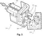
- the controlled connection comprises a part (371) fixed with respect to the transfer injection station and a part (372) linked to the forming die.
- the fixed part (371) comprises a pair of female contacts (311) insulated on their outer surface, capable of making a connection with a pair of male contacts (312) on the part (372) linked to the forming die.
- the connection is made by moving said female contacts (311), this moving being done by a double-acting pneumatic cylinder (375).
- Means (320) for circulating compressed air allow the contacts (311) to be cooled.
- the device which is the subject of the invention comprises two forming dies (411, 412) placed on the transfer plate (100).
- Said transfer plate (100) makes it possible to move the first (411) and the second die (412) alternately between the loading/unloading station and the injection station by making a portion of a turn, 90° or 180°.
- the device which is the subject of the invention makes it possible to produce two parts by operations carried out in parallel on these two parts according to a pendular cycle.
- Each forming die (411, 412) comprises a network of inductors (413) extending in cavities made in said die and cooling ducts (414) for the circulation of a fluid.
- the punch (120) positioned at the injection station is paired with the dies, defining with each of them a closed cavity when it is brought into contact with one of the forming dies, a closed cavity between the molding surfaces of the die and the punch.
- the molding surface of the punch comprises shapes (422) corresponding to the reliefs created on the part produced by overmoulding.
- said punch comprises means (421) for plastic injection into the closed cavity between the molding surfaces of the punch and the forming die.
- the punch also comprises cooling ducts (423) for the circulation of a fluid.
- the loading/unloading station comprises a device (130) for heating by radiating element.
- This heating device comprises, for example, a panel (431) of graphite, placed in a turn (432) which turn is connected to the high frequency generator (190) via the switch (160).
- the graphite panel (431) is heated by induction and quickly brought to high temperature, for example 1000° C.
- high emissivity coefficient of graphite makes it possible to transfer by radiation a large part of the energy used for its heating. Induction heating allows rapid heating of the radiant panel which avoids maintaining said panel permanently at high temperature, thus limiting its degradation by oxidation.
- the thermal radiation (435) generated by the device (130) for heating by radiating element makes it possible to bring the laminated composite blank (450) used for the production of the part, up to a temperature T1 suitable for its thermoforming, whereas said blank (450) is placed on die (412) at the loading/unloading station, but also to preheat the molding surface of said die (412) while the blank is placed on said die.
- Said blank (450) is deposited cold on the cold die (412), by an operator or a robot according to implementation variants.
- the blank is a lamination of fibrous plies in a completely consolidated or partially consolidated thermoplastic matrix, in this case the thermoforming operation corresponds to a stamping, or the blank consists of a lamination of non consolidated, and in this case the thermoforming operation approaches a form consolidation, the plies preimpregnated with a thermoplastic polymer being relatively rigid, even if the lamination is not consolidated.
- the heating temperature T1 suitable for thermoforming the blank is a temperature high enough to observe softening of the polymer constituting the matrix of the composite constituting the blank, and, depending on the nature of the reinforcements, sufficient to allow the interlaminar sliding of the fibrous plies. Depending on the nature of the blank and of the polymer constituting the matrix, this temperature is between the glass transition temperature and the melting temperature of the polymer. The temperature is determined in particular by tests depending on the nature of the flan.
- the molding surface of the matrix comprises a coating, for example a black chrome plating, or based on silicon carbide (SiC), making it possible to improve its absorption of infrared radiation and its heating by radiation.
- a pyrometer (not shown) makes it possible to measure the temperature of the blank or of the molding surface of the die during their heating by radiation.
- the surface of the die is preheated to a suitable temperature by the radiant panel (431) before depositing the blank.
- the switch (160) makes it possible to direct the power current, generated by the high frequency generator (190), via the controlled connection (170), towards the network of inductors (413) of the forming die (411) located at the injection site.
- part of the manufacturing steps (510 - 512) are implemented on the loading/unloading station and the other part of the manufacturing steps (520 - 524) is implemented on the thermoforming / injection station.
- the steps are carried out in parallel so as to increase the production rate.
- a demolding step (510) the previously thermoformed and overmolded part is removed from the forming die and the die is cleaned.
- a loading step (511) a composite blank is placed on the die.
- a preheating step (512) the blank and the forming die are brought to the radiation thermoforming temperature.
- the heating device by radiant means is supplied with high frequency current.
- the preheated die and blank are brought to the thermoforming and injection station.
- the part thermoformed and overmoulded in the other die is brought to the loading/unloading station.
- the blank is thermoformed.
- the network of inductors of the forming die is connected to the high frequency generator at the end of the transfer step.
- said matrix is maintained at a temperature at least equal to the thermoforming temperature to ensure uniform impregnation of the plies of the plane thus formed.
- This step aims at the subsequent consolidation of the lamination, which means the development of the molecular chains of the polymer through the interfaces between the plies of the lamination, and at the reduction of the porosities to an acceptable level with the intended application.
- the radiating means are no longer powered by the generator.
- a cooling step (522) the thermoformed blank located at the thermoforming/injection station is cooled to a temperature below the glass transition temperature of its polymer matrix but sufficient to allow overmolding.
- an injection step (523) overmolding is carried out.
- the inductor network of the forming die is no longer supplied, which makes it possible to supply the heating means by radiation.
- a cooling step (524) the mold made up of the forming die and the punch is cooled by fluid circulation, then the mold is opened before the transfer plate performs (513) a new rotation, bringing the finished part, on its forming die at the loading/unloading station where it is removed from the mould.
- the manufacturing operations are carried out in parallel on the two parts although a only high frequency generator is used.
- induction heating both for the dies and for the radiating means, allows rapid heating/cooling cycles over large temperature amplitudes, between the demolding temperature and the thermoforming temperature, and thus to have at the two transfer stations, a tool, a blank and a part; at temperatures suitable for the operations carried out at these stations, without delay.
- the device and the method that are the subject of the invention are suitable for a wide variety of thermoplastic composites, both as regards the nature of the fibers, the nature of the composite matrix as well as the nature of the polymer injected for the overmoulding.
- the blank preheating, temperature holding, injection and demolding temperatures are determined according to the materials used, based on existing data or tests. The achievement of these temperatures during the various stages and the organization of the corresponding means, in particular in terms of the number of inductors in the matrices, the installed induction power and the fluid flow in the cooling channels are for example obtained by numerical simulation of heating and cooling cycles.
Landscapes
- Engineering & Computer Science (AREA)
- Mechanical Engineering (AREA)
- Manufacturing & Machinery (AREA)
- Health & Medical Sciences (AREA)
- Physics & Mathematics (AREA)
- Composite Materials (AREA)
- Chemical & Material Sciences (AREA)
- Toxicology (AREA)
- Electromagnetism (AREA)
- Oral & Maxillofacial Surgery (AREA)
- Thermal Sciences (AREA)
- Moulds For Moulding Plastics Or The Like (AREA)
- Injection Moulding Of Plastics Or The Like (AREA)
- Processing Of Solid Wastes (AREA)
- Treatments For Attaching Organic Compounds To Fibrous Goods (AREA)
- Treatment Of Fiber Materials (AREA)
- Casting Or Compression Moulding Of Plastics Or The Like (AREA)
Description
- L'invention concerne un procédé et un dispositif pour la consolidation d'une préforme textile et la réalisation d'un surmoulage sur la pièce ainsi consolidée. L'invention est plus particulièrement adaptée à la réalisation d'une pièce en matériau composite renforcée par des fibres longues ou continues, sous la forme générale d'une coque, laquelle pièce comprend une face technique surmoulée, comprenant notamment des nervures, des rainures, des puits de fixation ou des éléments de positionnement ou d'assemblage, sans que cette liste ne soit limitative ni exhaustive.
- Un telle pièce est par exemple représentée par un capot de matériel électronique, tel un écran de télévision, mais l'invention est également applicable dans d'autres domaines, tels que l'automobile, l'aéronautique ou la bagagerie. L'utilisation d'une préforme textile à fibres longues ou continues permet de réduire le poids d'une telle pièce tout en augmentant sa résistance mécanique en comparaison des solutions de l'art antérieur utilisant un polymère injecté renforcé par des fibres courtes.
- À cette fin, selon l'art antérieur, un flan préconsolidé constitué d'un matériau composite thermoplastique stratifié à fibres continues est préchauffé à une température suffisante pour permettre le glissement interlaminaire des plis le constituant. Ledit flan est placé sur une matrice de formage et thermoformé à la forme de cette matrice, lors de la fermeture du moule. Après, ou concomitamment à la reconsolidation dudit flan en forme, la face technique est surmoulée par injection dans ce même moule, puis la pièce est démoulée après refroidissement.
- Ce cycle de fabrication entraîne des cycles thermiques de chauffage et de refroidissement tant du flan que du moule. Ainsi, pour réaliser le thermoformage le flan est porté à une température proche, voire supérieure à la température de fusion de sa matrice polymère, déconsolidant ainsi le flan, afin permettre le glissement interlaminaire des plis le constituant, alors que la matrice de formage, et le moule d'une manière générale, sont préchauffés à une température proche ou légèrement supérieure à la température de consolidation ou de transition vitreuse de ladite matrice polymère, la consolidation en forme du flan puis l'injection nécessite un refroidissement du moule à une température adaptée à la consolidation du flan mais suffisante pour permettre l'injection et le remplissage de tous les détails du moule, puis la pièce doit être refroidie à une température adaptée à son démoulage, avant l'ouverture du moule. Ledit moule doit ensuite être réchauffé pour reprendre le cycle. La durée des cycles de chauffage-refroidissement, définissent le temps de réalisation de la pièce. Lorsqu'ils sont mis en oeuvre par des moyens de chauffage indirect du moule, par exemple via une circulation fluide ou des résistances électriques parcourant le moule, ces temps sont longs en regard des cadences de production visées pour les pièces redevables de l'invention. Le chauffage du flan est, selon l'art antérieur, réalisé en dehors du moule par des panneaux radians dans l'infrarouge, ledit flan, une fois déconsolidé et prêt à être thermoformé, perd de sa cohésion et devient difficile à manipuler.
- La technique de chauffage par induction telle que décrite, notamment, dans le document
EP 1 894 442 , permet de chauffer et de refroidir rapidement un moule destiné au thermoformage ou à l'injection, et d'obtenir un contrôle fin tant de la température que de l'uniformité de cette température sur les surfaces moulantes du moule en limitant le volume du moule effectivement chauffé. Cette solution technique, si elle permet de contrôler la température d'un moule notamment d'injection ou de thermoformage ne permet pas de réaliser le préchauffage du flan. - Le document
EP 2 861 399 décrit une autre solution technique de chauffage des surfaces d'un moule, utilisant un élément rayonnant porté à haute température, placé en vis-à-vis desdites surfaces moulantes. Cette solution technique seule ne permet pas le contrôle de la température dans la cavité moulante une fois l'élément rayonnant écarté des surfaces et le moule fermé. - Le document
EP 1 136 239 et le documentWO 2011/023899 décrivent chacun un dispositif pour le thermoformage d'une pièce composite et le surmoulage par injection d'une forme sur une face de ladite pièce composite, dans un moule comportant une matrice de formage et un poinçon appairés définissant entre eux une cavité fermée. - Le document
US 2013/026678 décrit un moule pourvu d'un chauffage par induction et d'un circuit de refroidissement. - Les documents
US 2016/207818 etEP 0 576 196 décrivent chacun un dispositif comprenant un poste de chargement déchargement combiné avec un poste d'injection ou de surmoulage. - Le document
US 2010/276075 décrit un procédé de thermoformage d'un flan composite comprenant une opération de surmoulage dans l'outillage de thermoformage. - L'invention vise à résoudre les inconvénients de l'art antérieur pour la réalisation à haute cadence d'une pièce composite thermoformée comprenant un surmoulage, et concerne à cette fin un dispositif pour le thermoformage d'une pièce composite et le surmoulage par injection d'une forme sur une face de ladite pièce composite conformément à la revendication 1.
- Ainsi, le dispositif objet de l'invention permet de préchauffer directement le flan sur la matrice de formage avant de fermer moule pour réaliser l'injection. Le flan n'étant préchauffé qu'une fois placé sur la matrice de formage, il est facile à manipuler lors de son chargement, notamment par un robot.
- L'invention est avantageusement mise en oeuvre selon les modes de réalisation et les variantes exposés ci-après, lesquels sont à considérer individuellement ou selon toute combinaison techniquement opérante.
- Conformément à l'invention, l'élément rayonnant est un panneau chauffé par induction. Ainsi le panneau, par exemple un panneau en graphite, est porté rapidement à haute température et permet une chauffe rapide du flan et de la matrice de formage.
- Conformément à l'invention, le dispositif objet de l'invention comprend un générateur à haute fréquence, le réseau d'inducteurs de la matrice de formage et celui assurant le chauffage de l'élément rayonnant étant alimentés en courant haute fréquence par ce seul et même générateur, réduisant ainsi la puissance électrique installée et le coût de l'installation.
- Selon un mode de réalisation particulier, le dispositif objet de l'invention comprend un commutateur pour l'alimenter alternativement le réseau d'inducteurs de la matrice de formage et celui assurant le chauffage de l'élément rayonnant par le générateur haute fréquence unique. Le commutateur permet de changer facilement et automatiquement le poste du transfert alimenté en courant à haute fréquence par le générateur unique.
- Selon un mode de réalisation particulièrement avantageux, le dispositif objet de l'invention comporte deux matrices de formage chacune appairée avec le poinçon et comportant chacune un réseau d'inducteurs et un circuit de refroidissement pour le chauffage et le refroidissement de leurs surfaces moulantes, montées sur le transfert de sorte que l'une des matrices se trouve au poste de chargement-déchargement lorsque l'autre se trouve au poste de thermoformage et d'injection.
- Avantageusement, le circuit d'induction de chauffage de l'élément rayonnant ou le circuit comprenant le réseau d'inducteurs de la matrice de formage, comprend un coffret de capacités ou une bobine d'ajustement. Ces moyens permettent d'adapter l'impédance de chaque circuit et d'assurer le démarrage du générateur haute fréquence et son fonctionnement optimal, quelque soit le circuit alimenté, bien que ceux-ci aient des caractéristiques électriques différentes.
- L'invention concerne également un procédé pour la réalisation d'une pièce composite en forme comprenant un surmoulage, conformément à la revendication 5.
- Ainsi les tâches sont réalisées en parallèle et la cadence de production est augmentée. Lorsqu'une des matrices arrive au poste de chargement-déchargement celle-ci est dite froide, c'est-à-dire que sa température est au plus la température de démoulage. Il est alors facile de manipuler le flan, lui même à une température proche de la température ambiante, et de le placer sur ladite matrice, que ce soit par une opération manuelle ou par l'intermédiaire d'un robot.
- Conformément à l'invention, l'étape ii) comprend le chauffage du flan et de la matrice de formage au moyen de l'élément rayonnant.
- Selon un mode de réalisation mettant en oeuvre un dispositif selon l'invention comprenant un commutateur, ledit commutateur dirige l'alimentation en courant à haute fréquence vers les moyens de chauffage de l'élément rayonnant pendant l'étape ii) et vers le réseaux d'inducteurs la deuxième matrice de formage pendant les étapes iv) à vi).
- L'invention est exposée ci-après selon ses modes de réalisation préférés, nullement limitatifs, et en référence aux
figures 1 à5 , dans lesquelles : - la
figure 1 montre selon une vue en perspective un exemple de réalisation du dispositif objet de l'invention ; - la
figure 2 est une vue partielle en perspective d'un exemple de réalisation du commutateur sans ses capots ; - la
figure 3 représente selon une vue partielle en perspective, un exemple de réalisation de la connexion pilotée, sans ses capots, pour le raccordement électrique du réseau d'inducteurs de la matrice de formage au générateur haute fréquence au poste d'injection du dispositif objet de l'invention ; - la
figure 4 illustre selon une vue schématique en coupe, un exemple de réalisation du dispositif objet de l'invention comprenant deux matrices de formage ; - et la
figure 5 est un chronogramme d'un exemple de mise en oeuvre du dispositif objet de l'invention selon un exemple de réalisation du procédé objet de l'invention. -
Figure 1 , selon un exemple de réalisation du dispositif objet de l'invention dans un mode de réalisation ne comportant qu'une seule matrice de formage, ledit dispositif comprend un transfert circulaire (100) rotatif sur au moins un quart de tour (90°). Une matrice (110) est montée sur ledit transfert (100) et se trouve sur cette figure au poste d'injection, en face d'un poinçon (120) appairé avec ladite matrice et dont le déplacement vertical, est commandé par un vérin (121). Le déplacement vertical dudit poinçon (120) permet de fermer et d'ouvrir le moule constitué par le poinçon (120) et la matrice (110) dont les surfaces moulantes délimitent une cavité fermée comprenant la pièce lorsque le moule est fermé. Lorsque le plateau du transfert circulaire est tourné d'un quart de tour, ladite matrice (110) se trouve au poste de chargement / déchargement, sous un dispositif de préchauffage (130) comprenant un panneau rayonnant et des moyens pour permettre le chauffage de ce panneau rayonnant. À titre d'exemple non limitatif, le panneau rayonnant est constitué d'un panneau de graphite. Le dispositif est relié par une ligne de puissance (150) à un générateur de courant à haute fréquence (190). À titre d'exemple ledit générateur produit un courant à une fréquence comprise entre 10 kHz et 200 kHz pour une puissance comprise entre une dizaine et quelques centaines de KW, selon l'application visée. Un commutateur (160) permet d'alimenter en courant haute fréquence, à partir de ce générateur (190) unique, la matrice de formage (110) lorsqu'elle est au poste d'injection ou le dispositif de préchauffage (130) au poste de chargement / déchargement. Selon cet exemple de réalisation, le poste d'injection comprend en outre une connexion (170) pilotée coopérant avec des moyens associés à la matrice de formage (110) de sorte à alimenter électriquement un réseau d'inducteurs de ladite matrice. -
Figure 2 , selon un exemple de réalisation, le commutateur (160) comporte une arrivée (150) de courant électrique à haute fréquence, connectée d'un côté au générateur haute fréquence et de l'autre à un cavalier (260) constitué de deux blocs conducteurs, par exemple en cuivre. Selon cet exemple de réalisation, le cavalier (260) est apte à se déplacer selon un mouvement de translation commandé par un moteur électrique pas à pas (265), entre deux paires (261, 263) de contacts récepteurs, l'une (263) desdites paires étant connectée au circuit de chauffage par induction d'un panneau rayonnant et l'autre (261) au circuit d'induction comprenant un réseaux d'inducteurs dans la matrice de formage. Lesdits contacts récepteurs (261, 263) sont chacun constitués de deux blocs conducteurs, par exemple en cuivre. Un boîtier de commande électronique (290) pilote le moteur pas à pas (265) pour commuter l'alimentation haute fréquence entre le panneau rayonnant et le réseau d'inducteurs de la matrice de formage. Chacun des circuits électriques d'induction du panneau rayonnant et de la matrice de formage comprend, si besoin, un coffret de capacités et une bobine d'ajustement (non représentés), tels que décrits dans le documentEP 2 742 773 /US-2014-0183178 , de sorte à permettre le démarrage du générateur haute fréquence et son fonctionnement optimal lorsque celui-ci alimente l'un ou l'autre des circuits d'induction. -
Figure 3 , selon un exemple de réalisation, la connexion pilotée comprend une partie (371) fixe par rapport au poste d'injection du transfert et une partie (372) liée à la matrice de formage. La partie fixe (371) comprend une paire de contacts femelles (311) isolés sur leur surface extérieure, aptes réaliser une connexion avec une paire de contacts mâles (312) sur la partie (372) liée à la matrice de formage. Selon cet exemple de réalisation, la connexion est réalisée par le déplacement desdits contact femelles (311), ce déplacement étant réalisé par un vérin pneumatique (375) à double effet. Des moyens (320) de circulation d'air comprimé permettent de refroidir les contacts (311). -
Figure 4 , selon un mode de réalisation, le dispositif objet de l'invention comprend deux matrices de formage (411, 412) placées sur le plateau transfert (100). Ledit plateau transfert (100) permet de déplacer la première (411) et la seconde matrice (412) alternativement entre le poste de chargement / déchargement et le poste d'injection en réalisant une portion de tour, 90° ou 180°. Ainsi le dispositif objet de l'invention, selon ce mode de réalisation permet de réaliser deux pièces par des opérations réalisées en parallèle sur ces deux pièces selon un cycle pendulaire. Chaque matrice de formage (411, 412) comprend un réseau d'inducteurs (413) s'étendant dans des cavités réalisées dans ladite matrice et des conduits (414) de refroidissement pour la circulation d'un fluide. Ce mode de réalisation des matrices de formage et ses variantes sont décrits notamment dans le documentEP 1 894 442 . Le poinçon (120) positionné au poste d'injection, est appairé avec les matrices, définissant avec chacune d'elle une cavité fermée lorsque qu'il est mis en contact avec une des matrices de formage, cavité fermée comprise entre les surface moulantes de la matrice et du poinçon. La surface moulante du poinçon comprend des formes (422) correspondant aux reliefs créés sur la pièce réalisée par surmoulage. À cette fin, ledit poinçon comprend des moyens (421) d'injection plastique dans la cavité fermée comprise entre les surfaces moulantes du poinçon et de la matrice de formage. Selon un mode de réalisation, le poinçon comprend également des conduits (423) de refroidissement pour la circulation d'un fluide. Le poste de chargement / déchargement comprend un dispositif (130) de chauffage par élément rayonnant. Ce dispositif de chauffage comprend, par exemple, un panneau (431) de graphite, placé dans un spire (432) laquelle spire est connectée au générateur haute fréquence (190) via le commutateur (160). Lorsque ladite spire (432) est alimentée en courant haute fréquence, le panneau de graphite (431) est chauffé par induction et rapidement porté à haute température, par exemple 1000° C. Le coefficient d'émissivité élevé du graphite permet de transférer par rayonnement une grande part de l'énergie utilisée pour son chauffage. Le chauffage par induction permet un chauffage rapide du panneau rayonnant ce qui évite de maintenir ledit panneau en permanence à haute température, limitant ainsi sa dégradation par oxydation. Le rayonnement thermique (435) généré par le dispositif (130) de chauffage par élément rayonnant, permet de porter le flan (450) composite stratifié utilisé pour la réalisation de la pièce, jusqu'à une température T1 adaptée à son thermoformage, alors que ledit flan (450) se trouve posé sur la matrice (412) au poste de chargement / déchargement, mais aussi, de préchauffer la surface moulante de ladite matrice (412) pendant que le flan est posé sur ladite matrice. Ledit flan (450) est déposé froid sur la matrice (412) froide, par un opérateur ou un robot selon des variantes de mise en oeuvre. - Selon des exemple de réalisation, le flan est une stratification de plis fibreux dans un matrice thermoplastique complètement consolidée, ou partiellement consolidée, dans ce cas l'opération de thermoformage correspond à un estampage, ou le flan est constitué d'une stratification de plis non consolidée, et dans ce cas l'opération de thermoformage se rapproche d'une consolidation en forme, les plis préimprégnés d'un polymère thermoplastique étant relativement rigides, même si la stratification n'est pas consolidée.
- La température T1 de chauffage adaptée au thermoformage du flan est une température suffisamment élevée pour observer un ramollissement du polymère constituant la matrice du composite constituant le flan, et, selon la nature des renforts, suffisante pour permettre le glissement interlaminaire des plis fibreux. Selon la nature du flan et du polymère constituant la matrice, cette température se situe entre la température de transition vitreuse et la température de fusion du polymère. La température est déterminée notamment par essais en fonction de la nature du flan.
- Avantageusement la surface moulante de la matrice comprend un revêtement, par exemple un chromage noir, ou à base carbure de silicium (SiC), permettant d'améliorer son absorption du rayonnement infrarouge et son chauffage par rayonnement. Un pyromètre (non représenté) permet de mesurer la température du flan ou de la surface moulante de la matrice au cours de leur chauffage par rayonnement. Selon une variante, la surface de la matrice est préchauffée jusqu'à une température adaptée par le panneau rayonnant (431) avant de déposer le flan. Le commutateur (160) permet de diriger le courant de puissance, généré par le générateur haute fréquence (190), via la connexion pilotée (170), vers le réseau d'inducteurs (413) de la matrice de formage (411) se trouvant au poste d'injection.
-
Figure 5 , selon un exemple de mise en oeuvre du procédé objet de l'invention, une partie des étapes de fabrication (510 - 512) sont mise en oeuvre sur le poste de chargement / déchargement et l'autre partie des étapes de fabrication (520 - 524) est mise en oeuvre sur le poste de thermoformage / injection. Ainsi, les étapes sont réalisée en parallèle de manière à accroître la cadence de production. En partant du poste de chargement / déchargement, selon une étape de démoulage (510) la pièce préalablement thermoformée et surmoulée est retirée de la matrice de formage et la matrice est nettoyée. Au cours d'une étape (511) de chargement, un flan composite est posé sur la matrice. Au cours d'une étape (512) de préchauffage, le flan et la matrice de formage sont portés à la température de thermoformage par rayonnement. Pendant cette étape (512) le dispositif de chauffage par moyen rayonnant est alimenté en courant à haute fréquence. Par une rotation (513) du plateau transfert, la matrice et le flan préchauffés sont amenés au poste de thermoformage et d'injection. En même temps la pièce thermoformée et surmoulée dans l'autre matrice est amenée au poste de chargement / déchargement. Au cours d'une étape (520) de fermeture du moule le flan est thermoformé. Le réseau d'inducteurs de la matrice de formage est connecté au générateur haute fréquence à l'issue de l'étape de transfert. Au cours d'une étape (521) de maintien en température ladite matrice est maintenue à une température au moins égale à la température de thermoformage pour assurer une imprégnation uniforme des plis du plan ainsi formé. Cette étape vise à la consolidation subséquente de la stratification, laquelle s'entend du développement des chaînes moléculaires du polymère à travers les interfaces entre les plis de la stratification, et à la réduction des porosités à un niveau acceptable avec l'application visée. - Pendant cette étape de maintien en température les moyens rayonnants ne sont plus alimentés par le générateur. Au cours d'une étape (522) de refroidissement, le flan thermoformé se trouvant au poste de thermoformage / injection est refroidi jusqu'à une température inférieure à la température de transition vitreuse de sa matrice polymère mais suffisante pour permettre le surmoulage. Au cours d'une étape (523) d'injection, le surmoulage est réalisé. Durant cette étape le réseau d'inducteur de la matrice de formage n'est plus alimenté ce qui permet d'alimenter les moyens de chauffage par rayonnement. Au cours d'une étape (524) de refroidissement, le moule constitué de la matrice de formage et du poinçon est refroidi par circulation fluide, puis le moule est ouvert avant que le plateau transfert n'effectue (513) une nouvelle rotation, amenant la pièce finie, sur sa matrice de formage au poste de chargement / déchargement où elle est démoulée. Ainsi les opérations de fabrication sont réalisées en parallèle sur les deux pièces bien qu'un seul générateur haute fréquence ne soit utilisé.
- L'utilisation d'un chauffage par induction, tant pour les matrices que pour le moyen rayonnant permet des cycles de chauffage / refroidissement rapides sur des amplitudes de températures importantes, entre la température de démoulage et la température de thermoformage, et ainsi d'avoir au deux postes du transfert un outillage, un flan et une pièce; à des températures adaptées aux opérations réalisées sur ces postes, sans délai.
- Le dispositif et le procédé objets de l'invention sont adaptés à une grande variété de composites thermoplastique, tant en ce qui concerne la nature des fibres, la nature de la matrice composite ainsi que la nature du polymère injecté pour le surmoulage. Les températures de préchauffage du flan, de maintien en température, d'injection et de démoulage sont déterminées en fonction des matériaux mis en oeuvre, à partir de données existantes ou d'essais. L'atteinte de ces températures au cours des différentes étapes et l'organisation des moyens correspondants, notamment en termes de nombre d'inducteurs dans les matrices, de puissance d'induction installée et de débit fluide dans les canaux de refroidissement sont par exemple obtenus par simulation numérique des cycles de chauffage et de refroidissement.
- La description ci-avant et les exemples de réalisation, montrent que l'invention atteint le but visé, à savoir qu'elle permet de réaliser en parallèle les tâches de fabrication de deux pièces thermoformées et surmoulées, en doublant quasiment la cadence de production, tout en utilisant un générateur de courant haute fréquence unique, limitant ainsi la puissance électrique installée.
Claims (6)
- Dispositif pour le thermoformage d'une pièce composite et le surmoulage par injection d'une forme sur une face de ladite pièce composite, comprenant un moule comportant une matrice de formage (110, 411, 412) et un poinçon (120) appairés définissant entre eux une cavité fermée, ladite matrice de formage étant montée sur un transfert (100) comportant :- un poste de chargement déchargement d'un flan (150, 450)sur la matrice de formage (110, 411, 412) ;- un poste d'injection et de fermeture du moule entre le poinçon (120) et la matrice de formage (110, 411, 412) pour réaliser le thermoformage ;- un générateur à haute fréquence (190) ;- la matrice de formage comprenant un réseau d'inducteurs (413) pour le chauffage de sa surface moulante et un réseau de refroidissement (414) de ladite surface moulante par circulation fluide ;- le poste de chargement-déchargement comprenant un dispositif pour le placement d'un panneau rayonnant (431) chauffé par induction face à la surface moulante de la matrice de formage, le réseau d'inducteurs (413) de la matrice de formage et celui (432) assurant le chauffage du panneau rayonnant (431) chauffé par induction sont alimentés en courant haute fréquence par le seul et même générateur (190)
- Dispositif selon la revendication 1, comportant un commutateur (160) pour l'alimenter alternativement le réseau d'inducteurs (413) de la matrice de formage et celui (432) assurant le chauffage du panneau rayonnant (431) par le générateur haute fréquence (190) unique.
- Dispositif selon la revendication 1, dans lequel le circuit d'induction de chauffage du panneau rayonnant (431) ou le circuit comprenant le réseau d'inducteurs (413) de la matrice de formage, comprend un coffret de capacités ou une bobine d'ajustement.
- Dispositif selon la revendication 1, comportant une première et une deuxième matrice de formage (411, 412) chacune appairée avec le poinçon (120) et comportant chacune un réseau d'inducteurs (413) et un circuit de refroidissement (414) pour le chauffage et le refroidissement de leurs surfaces moulantes, montées sur le transfert (100) de sorte que l'une des matrices (412) se trouve au poste de chargement déchargement lorsque que l'autre (411) se trouve au poste de thermoformage - injection.
- Procédé pour la réalisation d'une pièce composite en forme comprenant un surmoulage, mettant en oeuvre un dispositif selon la revendication 4, comprenant les étapes consistant à :i. placer (511) sur la première matrice de formage (411) au poste de chargement/déchargement, un flan composite (450) ;ii. préchauffer (512) ladite matrice (411) et le flan (450) en contact avec celle-ci jusqu'à une température T1 adaptée au thermoformage dudit flan au moyen du dispositif selon la revendication 1 ;iii. transférer (513) la matrice au poste de thermoformage - injection ;iv. fermer (520) le moule sur ladite matrice en maintenant la température T1 de sorte à réaliser le thermoformage du flan ;v. refroidir (522) la matrice à une température T2 adaptée à la consolidation du flan et à l'injection ;vi. injecter (523) la partie surmoulée ;vii. refroidir (524) la cavité moulante jusqu'à la température de démoulage ;viii. ouvrir le moule ;ix. transférer (513) la première matrice au poste de chargement/déchargement ;x. démouler (511) la pièce et reprendre à l'étape i) procédé dans lequel les étapes i) et x) sont réalisées sur la première matrice en même temps que les étapes iv) à vi) sont réalisées sur la deuxième matrice et dans lequel l'étape ii) est réalisée sur la première matrice en même temps que les étapes vii) et viii) sur la deuxième matrice.
- Procédé selon la revendication 5, mettant en oeuvre un dispositif selon la revendication 2, dans lequel le commutateur (160) dirige l'alimentation en courant à haute fréquence vers les moyens de chauffage (431) du panneau rayonnant (431) pendant l'étape ii) et vers le réseaux d'inducteurs (413) de la deuxième matrice de formage pendant les étapes iv) à vi).
Applications Claiming Priority (2)
| Application Number | Priority Date | Filing Date | Title |
|---|---|---|---|
| FR1670612A FR3057487B3 (fr) | 2016-10-19 | 2016-10-19 | Procede et dispositif pour la consolidation d'une preforme textile et surmoulage. |
| PCT/EP2017/076650 WO2018073324A1 (fr) | 2016-10-19 | 2017-10-18 | Procédé et dispositif pour la consolidation d'une préforme textile et surmoulage |
Publications (2)
| Publication Number | Publication Date |
|---|---|
| EP3529028A1 EP3529028A1 (fr) | 2019-08-28 |
| EP3529028B1 true EP3529028B1 (fr) | 2022-12-07 |
Family
ID=60245060
Family Applications (1)
| Application Number | Title | Priority Date | Filing Date |
|---|---|---|---|
| EP17793873.5A Active EP3529028B1 (fr) | 2016-10-19 | 2017-10-18 | Procédé et dispositif pour la consolidation d'une préforme textile et surmoulage |
Country Status (8)
| Country | Link |
|---|---|
| US (1) | US11390001B2 (fr) |
| EP (1) | EP3529028B1 (fr) |
| JP (1) | JP6982071B2 (fr) |
| KR (1) | KR102448898B1 (fr) |
| CN (1) | CN110167735B (fr) |
| FR (1) | FR3057487B3 (fr) |
| TW (1) | TWI784979B (fr) |
| WO (1) | WO2018073324A1 (fr) |
Families Citing this family (5)
| Publication number | Priority date | Publication date | Assignee | Title |
|---|---|---|---|---|
| GB2567699B (en) * | 2017-10-23 | 2022-02-09 | Mclaren Automotive Ltd | Moulding arrangement |
| FR3096293B1 (fr) | 2019-05-23 | 2024-02-02 | Inst De Rech Tech Jules Verne | Dispositif et procédé de fabrication d’une pièce en matériau composite |
| CN114472858B (zh) * | 2022-01-12 | 2023-11-24 | 松阳县链条配件有限公司 | 一种高性能链板集成自动冲压成型工艺及其加工设备 |
| CN115782245B (zh) * | 2023-02-14 | 2023-04-11 | 中南大学 | 连续纤维增强热塑性复合材料复合构件的快速成形方法 |
| CN117484844B (zh) * | 2023-11-29 | 2026-02-06 | 东莞市振飞自动化机械有限公司 | 一种鞋底热冷成型装置及热冷成型方法 |
Family Cites Families (21)
| Publication number | Priority date | Publication date | Assignee | Title |
|---|---|---|---|---|
| CA2098409A1 (fr) | 1992-06-22 | 1993-12-23 | Chun P. Lau | Systeme de moulage automatique |
| JP3590718B2 (ja) * | 1997-03-10 | 2004-11-17 | アラコ株式会社 | 誘導コイルによる加熱機構を備えた成形装置 |
| US20090127253A1 (en) * | 1997-06-06 | 2009-05-21 | Philip Stark | Temperature-controlled induction heating of polymeric materials |
| FR2806349B1 (fr) * | 2000-03-20 | 2002-12-06 | Plastic Omnium Cie | Procede de fabrication d'une piece en matiere plastique renforcee |
| US7176648B2 (en) * | 2004-05-18 | 2007-02-13 | Husky Injection Molding Systems Ltd. | Energy management apparatus and method for injection molding systems |
| FR2887739B1 (fr) * | 2005-06-22 | 2007-08-31 | Roctool Soc Par Actions Simpli | Dispositif de chauffage par induction et procede de fabrication de pieces a l'aide d'un tel dispositif |
| EP1800829A1 (fr) * | 2005-12-22 | 2007-06-27 | Thermal Cyclic Technologies TCTech i Stockholm AB | Moule à injecter avec chauffage par induction et procédé de moulage avec une étappe de chauffage par induction. |
| ATE490863T1 (de) | 2006-08-08 | 2010-12-15 | Novem Car Interior Design Gmbh | Verkleben und beschichten von rohstofflagen |
| EP2679375A3 (fr) * | 2007-06-20 | 2014-04-23 | 3M Innovative Properties Company of 3M Center | Moulage par injection ultrasonore sur une toile |
| CN101610614B (zh) * | 2009-07-15 | 2012-06-20 | 杨东佐 | 一种模具温度控制装置及控制方法 |
| FR2949376B1 (fr) | 2009-08-28 | 2013-07-26 | Faurecia Interieur Ind | Procede de fabrication d'un habillage interieur de vehicule automobile comprenant un support et un revetement d'aspect ligneux |
| US9259886B2 (en) * | 2009-12-15 | 2016-02-16 | The Boeing Company | Curing composites out-of-autoclave using induction heating with smart susceptors |
| CN102114698A (zh) * | 2009-12-30 | 2011-07-06 | 广达电脑股份有限公司 | 注塑成型模具、预热装置及注塑成型模具进行预热的方法 |
| JP2012205802A (ja) * | 2011-03-30 | 2012-10-25 | Toto Ltd | 暖房便座装置 |
| US9156198B2 (en) | 2011-07-27 | 2015-10-13 | Flextronics Ap, Llc | Temperature controlled molding of composite components |
| FR2979047B1 (fr) | 2011-08-10 | 2014-09-19 | Roctool | Dispositf pour l'ajustement du facteur qualite d'un systeme de chauffage par induction notamment un moule a chauffage autonome |
| FR2991902A1 (fr) | 2012-06-18 | 2013-12-20 | Roctool | Procede et dispositif pour le prechauffage d'un moule notamment de moulage par injection |
| JP5559944B1 (ja) * | 2012-10-30 | 2014-07-23 | 三井造船株式会社 | 誘導加熱装置、誘導加熱装置の制御方法、及びプログラム |
| CN204109229U (zh) * | 2014-06-06 | 2015-01-21 | 昆山易昌泰塑胶有限公司 | 一种改进型可预加热模具的双色注塑机 |
| CN107107415A (zh) * | 2014-10-24 | 2017-08-29 | 东洋机械金属株式会社 | 立式注塑成型机及使用立式注塑成型机的复合成型体的成型方法 |
| KR102309386B1 (ko) | 2015-01-20 | 2021-10-06 | 삼성디스플레이 주식회사 | 윈도우 가공 장치 |
-
2016
- 2016-10-19 FR FR1670612A patent/FR3057487B3/fr not_active Expired - Fee Related
-
2017
- 2017-10-18 CN CN201780065018.1A patent/CN110167735B/zh active Active
- 2017-10-18 JP JP2019521044A patent/JP6982071B2/ja active Active
- 2017-10-18 EP EP17793873.5A patent/EP3529028B1/fr active Active
- 2017-10-18 US US16/340,630 patent/US11390001B2/en active Active
- 2017-10-18 WO PCT/EP2017/076650 patent/WO2018073324A1/fr not_active Ceased
- 2017-10-18 KR KR1020197013784A patent/KR102448898B1/ko active Active
- 2017-10-19 TW TW106135934A patent/TWI784979B/zh active
Also Published As
| Publication number | Publication date |
|---|---|
| CN110167735A (zh) | 2019-08-23 |
| JP2019532845A (ja) | 2019-11-14 |
| KR20190086674A (ko) | 2019-07-23 |
| EP3529028A1 (fr) | 2019-08-28 |
| KR102448898B1 (ko) | 2022-09-28 |
| JP6982071B2 (ja) | 2021-12-17 |
| US11390001B2 (en) | 2022-07-19 |
| US20200215733A1 (en) | 2020-07-09 |
| FR3057487B3 (fr) | 2018-12-07 |
| TW201819136A (zh) | 2018-06-01 |
| CN110167735B (zh) | 2021-08-13 |
| FR3057487A3 (fr) | 2018-04-20 |
| TWI784979B (zh) | 2022-12-01 |
| WO2018073324A1 (fr) | 2018-04-26 |
Similar Documents
| Publication | Publication Date | Title |
|---|---|---|
| CA2875233C (fr) | Procede et dispositif pour le prechauffage d'un moule notamment de moulage par injection | |
| WO2018073324A1 (fr) | Procédé et dispositif pour la consolidation d'une préforme textile et surmoulage | |
| CA2945246C (fr) | Dispositif pour le chauffage d'un moule | |
| EP2694277B1 (fr) | Dispositif et procédé pour le compactage-consolidation d'une pièce en matériau composite à matrice thermoplastique renforcée par des fibres continues notamment d'origine naturelle | |
| EP1728411A1 (fr) | Procede pour chauffer des materiaux en vue de produire des objets et dispositif mettant en oeuvre ce procede | |
| CA3071273A1 (fr) | Procede et dispositif pour la fabrication d'une piece composite de forme complexe | |
| EP2703146B1 (fr) | Procédé de refroidissement d'un moule par circulation d'un fluide caloporteur au contact de sa face externe | |
| FR2999970A1 (fr) | Procede de realisation d'une preforme textile a fibres continues par circulation d'un flux de gaz chaud a travers un ensemble fibreux | |
| EP1347869A1 (fr) | Moules pour la transformation des matieres plastiques et composites et procede de transformation associe | |
| EP2349667A1 (fr) | Dispositif de transformation de materiaux utilisant un chauffage par induction permettant un prechauffage du dispositif | |
| EP3455044B1 (fr) | Dispositif et procédé pour le moulage et la consolidation d'une préforme textile | |
| WO2020234313A1 (fr) | Dispositif et procédé de fabrication d'une pièce en matériau composite | |
| WO2020165307A1 (fr) | Système de régulation de température pour technologie de rotomoulage | |
| FR3047685A1 (fr) | Dispositif de fabrication, par moulage par injection, d'une piece comportant un insert | |
| WO2017194639A1 (fr) | Procédé et dispositif pour le chauffage d'un moule | |
| EP3281769B1 (fr) | Dispositif de moulage pour la mise en oeuvre de procedes de moulage a chaud et de moulage a froid | |
| EP0974446B1 (fr) | Machine de soudage d'objects creux et procédé pour souder ces objets | |
| WO2001051268A1 (fr) | Procede pour la mise en place d'une enveloppe en elastomere autour d'un corps de forme allongee |
Legal Events
| Date | Code | Title | Description |
|---|---|---|---|
| STAA | Information on the status of an ep patent application or granted ep patent |
Free format text: STATUS: UNKNOWN |
|
| STAA | Information on the status of an ep patent application or granted ep patent |
Free format text: STATUS: THE INTERNATIONAL PUBLICATION HAS BEEN MADE |
|
| PUAI | Public reference made under article 153(3) epc to a published international application that has entered the european phase |
Free format text: ORIGINAL CODE: 0009012 |
|
| STAA | Information on the status of an ep patent application or granted ep patent |
Free format text: STATUS: REQUEST FOR EXAMINATION WAS MADE |
|
| 17P | Request for examination filed |
Effective date: 20190515 |
|
| AK | Designated contracting states |
Kind code of ref document: A1 Designated state(s): AL AT BE BG CH CY CZ DE DK EE ES FI FR GB GR HR HU IE IS IT LI LT LU LV MC MK MT NL NO PL PT RO RS SE SI SK SM TR |
|
| AX | Request for extension of the european patent |
Extension state: BA ME |
|
| STAA | Information on the status of an ep patent application or granted ep patent |
Free format text: STATUS: EXAMINATION IS IN PROGRESS |
|
| 17Q | First examination report despatched |
Effective date: 20191018 |
|
| DAV | Request for validation of the european patent (deleted) | ||
| DAX | Request for extension of the european patent (deleted) | ||
| RIC1 | Information provided on ipc code assigned before grant |
Ipc: B29C 35/08 20060101ALN20220303BHEP Ipc: B29C 45/73 20060101ALI20220303BHEP Ipc: H05B 6/10 20060101ALI20220303BHEP Ipc: B29C 33/06 20060101ALI20220303BHEP Ipc: B29C 70/46 20060101ALI20220303BHEP Ipc: B29C 70/08 20060101ALI20220303BHEP Ipc: B29C 45/04 20060101ALI20220303BHEP Ipc: B29C 45/14 20060101AFI20220303BHEP |
|
| RIC1 | Information provided on ipc code assigned before grant |
Ipc: B29C 35/08 20060101ALN20220318BHEP Ipc: B29C 45/73 20060101ALI20220318BHEP Ipc: H05B 6/10 20060101ALI20220318BHEP Ipc: B29C 33/06 20060101ALI20220318BHEP Ipc: B29C 70/46 20060101ALI20220318BHEP Ipc: B29C 70/08 20060101ALI20220318BHEP Ipc: B29C 45/04 20060101ALI20220318BHEP Ipc: B29C 45/14 20060101AFI20220318BHEP |
|
| GRAP | Despatch of communication of intention to grant a patent |
Free format text: ORIGINAL CODE: EPIDOSNIGR1 |
|
| STAA | Information on the status of an ep patent application or granted ep patent |
Free format text: STATUS: GRANT OF PATENT IS INTENDED |
|
| RIC1 | Information provided on ipc code assigned before grant |
Ipc: B29C 35/08 20060101ALN20220330BHEP Ipc: B29C 45/73 20060101ALI20220330BHEP Ipc: H05B 6/10 20060101ALI20220330BHEP Ipc: B29C 33/06 20060101ALI20220330BHEP Ipc: B29C 70/46 20060101ALI20220330BHEP Ipc: B29C 70/08 20060101ALI20220330BHEP Ipc: B29C 45/04 20060101ALI20220330BHEP Ipc: B29C 45/14 20060101AFI20220330BHEP |
|
| INTG | Intention to grant announced |
Effective date: 20220504 |
|
| GRAS | Grant fee paid |
Free format text: ORIGINAL CODE: EPIDOSNIGR3 |
|
| RAP3 | Party data changed (applicant data changed or rights of an application transferred) |
Owner name: ROCTOOL |
|
| GRAA | (expected) grant |
Free format text: ORIGINAL CODE: 0009210 |
|
| STAA | Information on the status of an ep patent application or granted ep patent |
Free format text: STATUS: THE PATENT HAS BEEN GRANTED |
|
| AK | Designated contracting states |
Kind code of ref document: B1 Designated state(s): AL AT BE BG CH CY CZ DE DK EE ES FI FR GB GR HR HU IE IS IT LI LT LU LV MC MK MT NL NO PL PT RO RS SE SI SK SM TR |
|
| REG | Reference to a national code |
Ref country code: GB Ref legal event code: FG4D Free format text: NOT ENGLISH |
|
| REG | Reference to a national code |
Ref country code: CH Ref legal event code: EP Ref country code: AT Ref legal event code: REF Ref document number: 1536040 Country of ref document: AT Kind code of ref document: T Effective date: 20221215 |
|
| REG | Reference to a national code |
Ref country code: DE Ref legal event code: R096 Ref document number: 602017064419 Country of ref document: DE |
|
| REG | Reference to a national code |
Ref country code: IE Ref legal event code: FG4D Free format text: LANGUAGE OF EP DOCUMENT: FRENCH |
|
| REG | Reference to a national code |
Ref country code: LT Ref legal event code: MG9D |
|
| REG | Reference to a national code |
Ref country code: NL Ref legal event code: MP Effective date: 20221207 |
|
| PG25 | Lapsed in a contracting state [announced via postgrant information from national office to epo] |
Ref country code: SE Free format text: LAPSE BECAUSE OF FAILURE TO SUBMIT A TRANSLATION OF THE DESCRIPTION OR TO PAY THE FEE WITHIN THE PRESCRIBED TIME-LIMIT Effective date: 20221207 Ref country code: NO Free format text: LAPSE BECAUSE OF FAILURE TO SUBMIT A TRANSLATION OF THE DESCRIPTION OR TO PAY THE FEE WITHIN THE PRESCRIBED TIME-LIMIT Effective date: 20230307 Ref country code: LT Free format text: LAPSE BECAUSE OF FAILURE TO SUBMIT A TRANSLATION OF THE DESCRIPTION OR TO PAY THE FEE WITHIN THE PRESCRIBED TIME-LIMIT Effective date: 20221207 Ref country code: FI Free format text: LAPSE BECAUSE OF FAILURE TO SUBMIT A TRANSLATION OF THE DESCRIPTION OR TO PAY THE FEE WITHIN THE PRESCRIBED TIME-LIMIT Effective date: 20221207 Ref country code: ES Free format text: LAPSE BECAUSE OF FAILURE TO SUBMIT A TRANSLATION OF THE DESCRIPTION OR TO PAY THE FEE WITHIN THE PRESCRIBED TIME-LIMIT Effective date: 20221207 |
|
| REG | Reference to a national code |
Ref country code: AT Ref legal event code: MK05 Ref document number: 1536040 Country of ref document: AT Kind code of ref document: T Effective date: 20221207 |
|
| PG25 | Lapsed in a contracting state [announced via postgrant information from national office to epo] |
Ref country code: RS Free format text: LAPSE BECAUSE OF FAILURE TO SUBMIT A TRANSLATION OF THE DESCRIPTION OR TO PAY THE FEE WITHIN THE PRESCRIBED TIME-LIMIT Effective date: 20221207 Ref country code: PL Free format text: LAPSE BECAUSE OF FAILURE TO SUBMIT A TRANSLATION OF THE DESCRIPTION OR TO PAY THE FEE WITHIN THE PRESCRIBED TIME-LIMIT Effective date: 20221207 Ref country code: LV Free format text: LAPSE BECAUSE OF FAILURE TO SUBMIT A TRANSLATION OF THE DESCRIPTION OR TO PAY THE FEE WITHIN THE PRESCRIBED TIME-LIMIT Effective date: 20221207 Ref country code: HR Free format text: LAPSE BECAUSE OF FAILURE TO SUBMIT A TRANSLATION OF THE DESCRIPTION OR TO PAY THE FEE WITHIN THE PRESCRIBED TIME-LIMIT Effective date: 20221207 Ref country code: GR Free format text: LAPSE BECAUSE OF FAILURE TO SUBMIT A TRANSLATION OF THE DESCRIPTION OR TO PAY THE FEE WITHIN THE PRESCRIBED TIME-LIMIT Effective date: 20230308 |
|
| PG25 | Lapsed in a contracting state [announced via postgrant information from national office to epo] |
Ref country code: NL Free format text: LAPSE BECAUSE OF FAILURE TO SUBMIT A TRANSLATION OF THE DESCRIPTION OR TO PAY THE FEE WITHIN THE PRESCRIBED TIME-LIMIT Effective date: 20221207 |
|
| P01 | Opt-out of the competence of the unified patent court (upc) registered |
Effective date: 20230531 |
|
| PG25 | Lapsed in a contracting state [announced via postgrant information from national office to epo] |
Ref country code: SM Free format text: LAPSE BECAUSE OF FAILURE TO SUBMIT A TRANSLATION OF THE DESCRIPTION OR TO PAY THE FEE WITHIN THE PRESCRIBED TIME-LIMIT Effective date: 20221207 Ref country code: RO Free format text: LAPSE BECAUSE OF FAILURE TO SUBMIT A TRANSLATION OF THE DESCRIPTION OR TO PAY THE FEE WITHIN THE PRESCRIBED TIME-LIMIT Effective date: 20221207 Ref country code: PT Free format text: LAPSE BECAUSE OF FAILURE TO SUBMIT A TRANSLATION OF THE DESCRIPTION OR TO PAY THE FEE WITHIN THE PRESCRIBED TIME-LIMIT Effective date: 20230410 Ref country code: EE Free format text: LAPSE BECAUSE OF FAILURE TO SUBMIT A TRANSLATION OF THE DESCRIPTION OR TO PAY THE FEE WITHIN THE PRESCRIBED TIME-LIMIT Effective date: 20221207 Ref country code: CZ Free format text: LAPSE BECAUSE OF FAILURE TO SUBMIT A TRANSLATION OF THE DESCRIPTION OR TO PAY THE FEE WITHIN THE PRESCRIBED TIME-LIMIT Effective date: 20221207 Ref country code: AT Free format text: LAPSE BECAUSE OF FAILURE TO SUBMIT A TRANSLATION OF THE DESCRIPTION OR TO PAY THE FEE WITHIN THE PRESCRIBED TIME-LIMIT Effective date: 20221207 |
|
| PG25 | Lapsed in a contracting state [announced via postgrant information from national office to epo] |
Ref country code: SK Free format text: LAPSE BECAUSE OF FAILURE TO SUBMIT A TRANSLATION OF THE DESCRIPTION OR TO PAY THE FEE WITHIN THE PRESCRIBED TIME-LIMIT Effective date: 20221207 Ref country code: IS Free format text: LAPSE BECAUSE OF FAILURE TO SUBMIT A TRANSLATION OF THE DESCRIPTION OR TO PAY THE FEE WITHIN THE PRESCRIBED TIME-LIMIT Effective date: 20230407 Ref country code: AL Free format text: LAPSE BECAUSE OF FAILURE TO SUBMIT A TRANSLATION OF THE DESCRIPTION OR TO PAY THE FEE WITHIN THE PRESCRIBED TIME-LIMIT Effective date: 20221207 |
|
| REG | Reference to a national code |
Ref country code: DE Ref legal event code: R097 Ref document number: 602017064419 Country of ref document: DE |
|
| PLBE | No opposition filed within time limit |
Free format text: ORIGINAL CODE: 0009261 |
|
| STAA | Information on the status of an ep patent application or granted ep patent |
Free format text: STATUS: NO OPPOSITION FILED WITHIN TIME LIMIT |
|
| PG25 | Lapsed in a contracting state [announced via postgrant information from national office to epo] |
Ref country code: DK Free format text: LAPSE BECAUSE OF FAILURE TO SUBMIT A TRANSLATION OF THE DESCRIPTION OR TO PAY THE FEE WITHIN THE PRESCRIBED TIME-LIMIT Effective date: 20221207 |
|
| 26N | No opposition filed |
Effective date: 20230908 |
|
| PG25 | Lapsed in a contracting state [announced via postgrant information from national office to epo] |
Ref country code: SI Free format text: LAPSE BECAUSE OF FAILURE TO SUBMIT A TRANSLATION OF THE DESCRIPTION OR TO PAY THE FEE WITHIN THE PRESCRIBED TIME-LIMIT Effective date: 20221207 |
|
| PG25 | Lapsed in a contracting state [announced via postgrant information from national office to epo] |
Ref country code: MC Free format text: LAPSE BECAUSE OF FAILURE TO SUBMIT A TRANSLATION OF THE DESCRIPTION OR TO PAY THE FEE WITHIN THE PRESCRIBED TIME-LIMIT Effective date: 20221207 |
|
| REG | Reference to a national code |
Ref country code: CH Ref legal event code: PL |
|
| REG | Reference to a national code |
Ref country code: BE Ref legal event code: MM Effective date: 20231031 |
|
| PG25 | Lapsed in a contracting state [announced via postgrant information from national office to epo] |
Ref country code: LU Free format text: LAPSE BECAUSE OF NON-PAYMENT OF DUE FEES Effective date: 20231018 |
|
| GBPC | Gb: european patent ceased through non-payment of renewal fee |
Effective date: 20231018 |
|
| PG25 | Lapsed in a contracting state [announced via postgrant information from national office to epo] |
Ref country code: LU Free format text: LAPSE BECAUSE OF NON-PAYMENT OF DUE FEES Effective date: 20231018 |
|
| PG25 | Lapsed in a contracting state [announced via postgrant information from national office to epo] |
Ref country code: GB Free format text: LAPSE BECAUSE OF NON-PAYMENT OF DUE FEES Effective date: 20231018 |
|
| PG25 | Lapsed in a contracting state [announced via postgrant information from national office to epo] |
Ref country code: CH Free format text: LAPSE BECAUSE OF NON-PAYMENT OF DUE FEES Effective date: 20231031 |
|
| PG25 | Lapsed in a contracting state [announced via postgrant information from national office to epo] |
Ref country code: GB Free format text: LAPSE BECAUSE OF NON-PAYMENT OF DUE FEES Effective date: 20231018 Ref country code: CH Free format text: LAPSE BECAUSE OF NON-PAYMENT OF DUE FEES Effective date: 20231031 |
|
| PG25 | Lapsed in a contracting state [announced via postgrant information from national office to epo] |
Ref country code: BE Free format text: LAPSE BECAUSE OF NON-PAYMENT OF DUE FEES Effective date: 20231031 |
|
| PG25 | Lapsed in a contracting state [announced via postgrant information from national office to epo] |
Ref country code: IE Free format text: LAPSE BECAUSE OF NON-PAYMENT OF DUE FEES Effective date: 20231018 |
|
| PG25 | Lapsed in a contracting state [announced via postgrant information from national office to epo] |
Ref country code: IE Free format text: LAPSE BECAUSE OF NON-PAYMENT OF DUE FEES Effective date: 20231018 |
|
| PG25 | Lapsed in a contracting state [announced via postgrant information from national office to epo] |
Ref country code: BG Free format text: LAPSE BECAUSE OF FAILURE TO SUBMIT A TRANSLATION OF THE DESCRIPTION OR TO PAY THE FEE WITHIN THE PRESCRIBED TIME-LIMIT Effective date: 20221207 |
|
| PG25 | Lapsed in a contracting state [announced via postgrant information from national office to epo] |
Ref country code: BG Free format text: LAPSE BECAUSE OF FAILURE TO SUBMIT A TRANSLATION OF THE DESCRIPTION OR TO PAY THE FEE WITHIN THE PRESCRIBED TIME-LIMIT Effective date: 20221207 |
|
| PG25 | Lapsed in a contracting state [announced via postgrant information from national office to epo] |
Ref country code: CY Free format text: LAPSE BECAUSE OF FAILURE TO SUBMIT A TRANSLATION OF THE DESCRIPTION OR TO PAY THE FEE WITHIN THE PRESCRIBED TIME-LIMIT; INVALID AB INITIO Effective date: 20171018 |
|
| PG25 | Lapsed in a contracting state [announced via postgrant information from national office to epo] |
Ref country code: HU Free format text: LAPSE BECAUSE OF FAILURE TO SUBMIT A TRANSLATION OF THE DESCRIPTION OR TO PAY THE FEE WITHIN THE PRESCRIBED TIME-LIMIT; INVALID AB INITIO Effective date: 20171018 |
|
| PG25 | Lapsed in a contracting state [announced via postgrant information from national office to epo] |
Ref country code: TR Free format text: LAPSE BECAUSE OF FAILURE TO SUBMIT A TRANSLATION OF THE DESCRIPTION OR TO PAY THE FEE WITHIN THE PRESCRIBED TIME-LIMIT Effective date: 20221207 |
|
| PGFP | Annual fee paid to national office [announced via postgrant information from national office to epo] |
Ref country code: DE Payment date: 20251030 Year of fee payment: 9 |
|
| PGFP | Annual fee paid to national office [announced via postgrant information from national office to epo] |
Ref country code: IT Payment date: 20251029 Year of fee payment: 9 |
|
| PGFP | Annual fee paid to national office [announced via postgrant information from national office to epo] |
Ref country code: FR Payment date: 20251030 Year of fee payment: 9 |