EP3528914B1 - Ölüberwachungssystem - Google Patents
Ölüberwachungssystem Download PDFInfo
- Publication number
- EP3528914B1 EP3528914B1 EP17865322.6A EP17865322A EP3528914B1 EP 3528914 B1 EP3528914 B1 EP 3528914B1 EP 17865322 A EP17865322 A EP 17865322A EP 3528914 B1 EP3528914 B1 EP 3528914B1
- Authority
- EP
- European Patent Office
- Prior art keywords
- fluid
- fluid flow
- wall
- flow
- separation chamber
- Prior art date
- Legal status (The legal status is an assumption and is not a legal conclusion. Google has not performed a legal analysis and makes no representation as to the accuracy of the status listed.)
- Active
Links
Images






Classifications
-
- C—CHEMISTRY; METALLURGY
- C02—TREATMENT OF WATER, WASTE WATER, SEWAGE, OR SLUDGE
- C02F—TREATMENT OF WATER, WASTE WATER, SEWAGE, OR SLUDGE
- C02F1/00—Treatment of water, waste water, or sewage
- C02F1/40—Devices for separating or removing fatty or oily substances or similar floating material
-
- B—PERFORMING OPERATIONS; TRANSPORTING
- B01—PHYSICAL OR CHEMICAL PROCESSES OR APPARATUS IN GENERAL
- B01D—SEPARATION
- B01D17/00—Separation of liquids, not provided for elsewhere, e.g. by thermal diffusion
- B01D17/02—Separation of non-miscible liquids
- B01D17/0208—Separation of non-miscible liquids by sedimentation
- B01D17/0211—Separation of non-miscible liquids by sedimentation with baffles
-
- B—PERFORMING OPERATIONS; TRANSPORTING
- B01—PHYSICAL OR CHEMICAL PROCESSES OR APPARATUS IN GENERAL
- B01D—SEPARATION
- B01D17/00—Separation of liquids, not provided for elsewhere, e.g. by thermal diffusion
- B01D17/02—Separation of non-miscible liquids
- B01D17/0208—Separation of non-miscible liquids by sedimentation
- B01D17/0214—Separation of non-miscible liquids by sedimentation with removal of one of the phases
-
- B—PERFORMING OPERATIONS; TRANSPORTING
- B01—PHYSICAL OR CHEMICAL PROCESSES OR APPARATUS IN GENERAL
- B01D—SEPARATION
- B01D17/00—Separation of liquids, not provided for elsewhere, e.g. by thermal diffusion
- B01D17/12—Auxiliary equipment particularly adapted for use with liquid-separating apparatus, e.g. control circuits
-
- C—CHEMISTRY; METALLURGY
- C02—TREATMENT OF WATER, WASTE WATER, SEWAGE, OR SLUDGE
- C02F—TREATMENT OF WATER, WASTE WATER, SEWAGE, OR SLUDGE
- C02F1/00—Treatment of water, waste water, or sewage
- C02F1/008—Control or steering systems not provided for elsewhere in subclass C02F
-
- C—CHEMISTRY; METALLURGY
- C02—TREATMENT OF WATER, WASTE WATER, SEWAGE, OR SLUDGE
- C02F—TREATMENT OF WATER, WASTE WATER, SEWAGE, OR SLUDGE
- C02F2101/00—Nature of the contaminant
- C02F2101/30—Organic compounds
- C02F2101/32—Hydrocarbons, e.g. oil
-
- C—CHEMISTRY; METALLURGY
- C02—TREATMENT OF WATER, WASTE WATER, SEWAGE, OR SLUDGE
- C02F—TREATMENT OF WATER, WASTE WATER, SEWAGE, OR SLUDGE
- C02F2103/00—Nature of the water, waste water, sewage or sludge to be treated
- C02F2103/001—Runoff or storm water
-
- C—CHEMISTRY; METALLURGY
- C02—TREATMENT OF WATER, WASTE WATER, SEWAGE, OR SLUDGE
- C02F—TREATMENT OF WATER, WASTE WATER, SEWAGE, OR SLUDGE
- C02F2103/00—Nature of the water, waste water, sewage or sludge to be treated
- C02F2103/34—Nature of the water, waste water, sewage or sludge to be treated from industrial activities not provided for in groups C02F2103/12 - C02F2103/32
- C02F2103/36—Nature of the water, waste water, sewage or sludge to be treated from industrial activities not provided for in groups C02F2103/12 - C02F2103/32 from the manufacture of organic compounds
- C02F2103/365—Nature of the water, waste water, sewage or sludge to be treated from industrial activities not provided for in groups C02F2103/12 - C02F2103/32 from the manufacture of organic compounds from petrochemical industry (e.g. refineries)
-
- C—CHEMISTRY; METALLURGY
- C02—TREATMENT OF WATER, WASTE WATER, SEWAGE, OR SLUDGE
- C02F—TREATMENT OF WATER, WASTE WATER, SEWAGE, OR SLUDGE
- C02F2201/00—Apparatus for treatment of water, waste water or sewage
- C02F2201/002—Construction details of the apparatus
-
- C—CHEMISTRY; METALLURGY
- C02—TREATMENT OF WATER, WASTE WATER, SEWAGE, OR SLUDGE
- C02F—TREATMENT OF WATER, WASTE WATER, SEWAGE, OR SLUDGE
- C02F2209/00—Controlling or monitoring parameters in water treatment
- C02F2209/003—Downstream control, i.e. outlet monitoring, e.g. to check the treating agents, such as halogens or ozone, leaving the process
-
- C—CHEMISTRY; METALLURGY
- C02—TREATMENT OF WATER, WASTE WATER, SEWAGE, OR SLUDGE
- C02F—TREATMENT OF WATER, WASTE WATER, SEWAGE, OR SLUDGE
- C02F2209/00—Controlling or monitoring parameters in water treatment
- C02F2209/11—Turbidity
-
- C—CHEMISTRY; METALLURGY
- C02—TREATMENT OF WATER, WASTE WATER, SEWAGE, OR SLUDGE
- C02F—TREATMENT OF WATER, WASTE WATER, SEWAGE, OR SLUDGE
- C02F2301/00—General aspects of water treatment
- C02F2301/02—Fluid flow conditions
- C02F2301/028—Tortuous
Definitions
- oil handling facilities 10 such as petroleum storage facilities 12, petroleum processing facilities 14 such as oil refineries 15, and oil mining facilities 19 such as oil wells 17, and the like, are typically disposed in containment areas 16 that are designed to contain liquids that become contaminated with hydrocarbons.
- oil handling facilities can be susceptible to storm water, either in the form of run off or accumulation on the storage tanks. The storm water that runs off from oil handling facilities can become contaminated with hydrocarbons.
- the containment areas 16 are designed to contain the storm water run off, thereby preventing the possibility of contaminants in the run off from entering the ambient environment outside the containment area 16.
- oil handling facilities 10 can also include run off retention ponds that are configured to receive and store storm water run off.
- Floating roofs are conventionally employed as a way to safely store the contained petroleum with minimal escape of petroleum vapors into the environment.
- the floating roof is sealed with respect to the outer tank wall, such that as the volume of stored petroleum changes, the floating roof slides along the side wall of the tank without allowing leakage at the interface of the floating roof and the side wall of the tank. It is recognized that the floating roof and the portion of the side wall of the tank that resides above the floating roof can cooperate to define a basin that collects storm water. If the collected storm water is allowed to remain, the volume of storm water can collect in an amount sufficient to compromise the structural integrity of the roof.
- WO2015026722A1 relates to a water treatment system for treating water from oil production streams, where the system includes an inlet line, a tank in fluid communication with the inlet line to receive therefrom a fluid flow comprising hydrocarbons and water.
- WO2009009648A2 relates to systems and methods for separating hydrocarbons from water.
- WO9405601A1 relates to an apparatus and method for removing particles of a first liquid having a lighter density, such as oil, from a second liquid having a greater density, such as water.
- US4425239A relates to a system for separating a multi-component fluid such as a water-in-oil emulsion into at least two components.
- WO2009091977A1 relates to a trap for removing buoyant material from fluid, the trap comprising: a treatment tank comprising a base wall and a vertically-extending sidewall; a feed pipe adapted to introduce a fluid flow at a first location in the treatment tank; an exit pipe adapted to remove at least a portion of the fluid flow from a second location in the treatment tank; and one or more wall structures adapted to form a circuitous passage, with respect to a horizontal plane, between the first location and the second location, the one or more wall structures extending from the base wall to a point below the sidewall and being open at a top end thereof.
- WO2016/172458 discloses a monitoring system configured to detect a threshold amount of petroleum in a storm water-based fluid of an oil handling facility.
- the storm water-based fluid can be drained from a floating roof of a petroleum storage tank, a diked area, or a retention pond.
- a monitoring system 20 is configured to detect the presence of a selected group of hydrocarbons in a fluid 22 to be discharged from a location of an oil handling facility.
- the selected group of hydrocarbons can include, but is not necessarily limited to, diesel/fuel oil, lube oil, motor oil, hydraulic oil, jet fuel, mineral oil, and crude oil.
- reference herein to hydrocarbons refers to the selected group of hydrocarbons unless otherwise indicated.
- the oil handling facility can be in the form of a petroleum storage facility 23 (see Fig. 11A ), an oil processing facility 25 (see Fig. 11B ), or an oil mining facility 33 (see Fig. 11C ).
- the location of the oil handling facility can be a floating roof of a petroleum storage tank, or a retention pond of an oil processing facility or oil mining facility. While the monitoring system will now be described in conjunction with a petroleum storage facility, it will be appreciated from the description below that the monitoring system can be used in conjunction with an oil processing facility or an oil mining facility.
- the petroleum storage facility 23 includes at least one petroleum storage tank 26 such as a plurality of petroleum storage tanks 26 that each has a floating roof 24.
- the petroleum storage tank 26 can be dimensioned to store any suitable volume of petroleum as desired, from several hundred thousands of gallons (litres) of petroleum to several million gallons (litres) of petroleum.
- the fluid 22 can be a storm water-based fluid.
- the monitoring system 20 can include one or more up to all of the oil handling facility, a fluid flow separation chamber 28, a first or an inlet conduit 30 that extends from the oil handling facility to an inlet 29 (see Figs. 5A , 13A , 14A , and 15A ) of the fluid flow separation chamber 28, and a hydrocarbon sensor 34 that is configured to be supported by the fluid flow separation chamber 28.
- the inlet conduit 30 extends from the petroleum storage tank 26 to the inlet 29, and is configured to deliver fluid 22 that is discharged from the petroleum storage tank 26 to the fluid flow separation chamber 28.
- the monitoring system 20 can further include a heater 81 that is configured to deliver heat to the inlet conduit 30, thereby preventing the fluid from freezing in the inlet conduit 30 during periods of cold weather.
- the monitoring system 20 can further include a second or outlet conduit 32 having a first end attached to an outlet 31 (see Figs. 5A , 13A , 14A , and 15A ) of the fluid flow separation chamber 28, and a second end configured to deliver the fluid 22 to a location in the environment, such as the earth.
- the outlet conduit 32 can define an inner cross-sectional area that is greater than that of the inlet conduit 30.
- the outlet conduit 32 can define an inner diameter that is greater than that of the inlet conduit 30.
- the outlet conduit 32 can have an inner diameter of five inches (12.7 cm) or greater (such as between 5 inches (12.7 cm) and 10 inches (25.4 cm)), and the inlet conduit 30 can have an inner diameter of less than five inches (12.7 cm) (such as between 2 inches (5.08 cm) and 5 inches (12.7 cm)), though it should be appreciated that the inner diameters of the inlet conduit 30 and the outlet conduit 32 can be alternatively dimensioned as desired. It should be further appreciated that the size of the separation chamber 28 and conduits can be scaled up or down depending on the volume of fluid 22 that is expected to be received by the fluid flow separation chamber 28 in a given application.
- the monitoring system 20 can include a hydrocarbon sensor 34 that is configured to detect the threshold amount of hydrocarbons in the fluid 22 at a location inside the fluid flow separation chamber 28.
- the hydrocarbons can, for instance, be present in petroleum that has entered the fluid 22 from the storage tank 26.
- the hydrocarbon sensor 34 can be referred to as a petroleum sensor
- the monitoring system 20 can be referred to as a petroleum monitoring system.
- the fluid flow separation chamber 28 is configured to cause hydrocarbons present in the fluid 22 to rise to the upper surface of the fluid 22 to create a sheen, such that it can be reliably detected by the hydrocarbon sensor 34.
- the fluid flow separation chamber 28 can be configured to disrupt the flow of the fluid 22 from the inlet 29 to the outlet 31 so as to cause hydrocarbons present in the fluid 22 to rise to the upper surface of the fluid 22.
- the fluid flow separation chamber 28 can include one or more features that disrupt the flow of the fluid between the inlet 29 to the outlet 31.
- the monitoring system 20 can prevent the delivery of the fluid 22 into the environment when the hydrocarbon sensor 34 detects the predetermined threshold amount of petroleum in the fluid 22.
- the threshold amount can be any amount of petroleum in the fluid 22 that is greater than zero.
- the threshold amount can be any amount of petroleum that produces a sheen on an upper surface of the fluid 22.
- the hydrocarbon sensor 34 can be constructed as described in U.S. Patent No. 7,688,428 . It should be appreciated, of course, that the hydrocarbon sensor 34 can be constructed in accordance with any alternative embodiment as desired, suitable to detect petroleum present in a fluid.
- the petroleum storage tank 26 can include a base 36, and at least one side wall 38 that extends up from the base 36.
- the side wall 38 can define an inner surface 38a and an outer surface 38b opposite the inner surface.
- the inner surface 38a can at least partially define an interior 40 of the storage tank 26 that is configured to house a quantity of petroleum.
- the base 36, the side wall 38, and the floating roof 24 can cooperate so as to define the interior 40 of the storage tank 26.
- the at least one side wall 38 can be configured as a cylindrical wall, or can define any suitable alternative shape as desired.
- the floating roof 24 defines a lower surface 24a and an upper surface 24b opposite the lower surface 24a.
- the lower surface 24a is configured to face the interior 40 of the storage tank 26.
- the floating roof 24 rises with respect to the at least one side wall 38.
- the floating roof 24 falls with respect to the at least one side wall 38.
- the floating roof 24 can ride along the inner surface 38a of the at least one side wall 38 as the floating roof 24 rises and falls.
- the floating roof 24 can be sealed against the inner surface 38a of the side wall 38 so as to prevent the leakage of petroleum through the interface between the floating roof 24 and the inner surface 38a of the side wall 38, and into the environment. Further the sealed interface between the floating roof 24 and the inner surface 38a of the side wall 38 can prevent environmental contaminants from entering the interior 40 of the petroleum storage tank 26. In the event that water were to enter the interior 40 of the storage tank 26, the water is typically drained through a sump in the base 36 of the storage tank 26, and removed from the stored petroleum.
- the lower surface 24a of the floating roof 24 is configured to ride along the upper surface of the petroleum stored in the interior 40 of the storage tank 26.
- the floating roof 24 is configured to ride along the upper surface of the petroleum contained in the interior 40 of the storage tank 26 as the volume of petroleum contained in the interior increases and decreases. It should be appreciated that the volume of petroleum in the interior 40 of the storage tank 26 can cause the floating roof 24 to be positioned at a location such that the upper surface 24b of the floating roof 24 is disposed below an upper end of the at least one side wall 38.
- the upper surface 24b of the floating roof 24 and the inner surface 38a of the side wall 38 at an upper portion 39 of the side wall 38 that is disposed above the floating roof 24 can define a basin 42 that can be configured to collect the fluid 22, which can be provided as storm water during periods of rain.
- the storage tank 26 can include a drain 44 that extends through the floating roof 24 from the upper surface 24b to the lower surface 24a.
- the inlet conduit 30 can extend from the floating roof 24, and in particular from the drain 44, through the interior 40 of the petroleum storage tank 26, and out the petroleum storage tank 26 to the inlet 29 of the fluid flow separation chamber 28.
- the inlet conduit 30 places the drain 44 in fluid communication with the fluid flow separation chamber 28.
- the inlet conduit 30 can have any dimension as desired, such as a cross-sectional dimension between one inch and ten inches.
- the inlet conduit 30 can include a butterfly valve or any suitable alternative actuated valve as desired configured to regulate the flow of the fluid 22 through the inlet conduit.
- the inlet conduit 30 includes a first conduit segment 30a that extends from the drain 44 in the floating roof 24.
- the first conduit segment 30a can be coupled to the lower surface 24a of the floating roof 24 inside the interior 40 of the petroleum storage tank 26, and in fluid communication with the drain 44.
- the first conduit segment 30a can, for instance be coupled to the lower surface 24a of the floating roof 24 via a flexible or otherwise movable joint 46.
- the inlet conduit 30 can further include a second inlet conduit segment 30b that extends between the first inlet conduit segment 30a and the inlet 29 of the fluid flow separation chamber 28.
- the second inlet conduit segment 30b can be movably coupled with respect to the first inlet conduit segment 30a.
- the second conduit segment 30b can attach at a first end to the inlet 29 of the fluid flow separation chamber 28.
- the second conduit segment 30b can attach at a second end, opposite the first end, to the first conduit segment 30a.
- the inlet conduit 30 can include at least one intermediate conduit segment 30' coupled from the second end of the second conduit segment 30b to the first conduit segment 30a.
- the conduit segments can be attached to each other via a flexible or otherwise movable joint 46 as described above.
- first end of the second conduit segment 30b can be attached to the inlet 29 of the fluid flow separation chamber 28 via the movable joint 46.
- orientation of the second conduit 30b can remain constant as the floating roof 24 is raised and lowered with respect to the at least one side wall 38 due to the inclusion of the at least one intermediate conduit segment, the first end of the second conduit 30b can be fixedly attached to the inlet 29 of the fluid flow separation chamber 28.
- the inlet conduit 30 can place the drain 44 in fluid communication with the inlet 29 of the fluid flow separation chamber both when the floating roof 24 is at a first vertical position with respect to the at least one side wall 38, and when the floating roof 24 is at a second vertical position with respect to the at least one side wall 38 that is different than the first position.
- the conduit segments 30a, 30b, and 30' can be attached to each other via the movable joint 46. Accordingly, as the floating roof 24 rises and lowers with respect to the at least one side wall 38, the movable joint 46 allows the conduit segments to change in orientation and position with respect to the floating roof 24 without compromising the sealed interface between the first conduit segment 30a and the floating roof 24.
- one or more of the conduit segments 30a, 30b, and 30' can be flexible conduits.
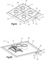
- the fluid flow separation chamber 28 defines a chamber body 48, such that the inlet 29 and the outlet 31 extend through the chamber body 48.
- the outlet 31 is positioned downstream from the inlet 29 with respect to the direction of the flow of fluid 22 through the chamber 28.
- the chamber body 48 includes a base 50 and at least one outer wall 52 that extends up from the base 50.
- the outer wall 52 extends up from the base 50 along a transverse direction T.
- the transverse direction T can be oriented in a vertical direction during use.
- the base 50 and the outer wall 52 each defines a respective inner surface that cooperate with each other to define an interior 53 of the fluid flow separation chamber 28.
- the fluid flow separation chamber 28 can further include a heater that is configured to deliver heat to the chamber body 48, for instance the base 50, so as to prevent fluid 22 disposed in the interior 53 of the separation chamber 28 from freezing.
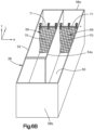
- the chamber body 48 and thus the fluid flow separation chamber 28, further includes a plurality of baffles 54 that extend up from the base 50.
- the baffles 54 extend up from the base 50 along the transverse direction T.
- the baffles 54 are disposed adjacent each other along a lateral direction A that is perpendicular to the transverse direction T.
- the lateral direction A can thus be oriented in a horizontal direction during use.
- the chamber body 48 including the base 50, the baffles 54, and the outer wall 52, can be made of any suitable material as desired. In one example, the chamber body 48 can be metallic.
- the fluid flow separation chamber 28 defines a plurality of fluid flow channels 56 that are configured to deliver the fluid from the inlet 29 to the outlet 31.
- the fluid flow channels 56 are defined between adjacent ones of the baffles 54.
- the fluid flow channels 56 can further be defined between outermost ones of the baffles 54 and the at least one outer wall 52.
- the fluid flow channels 56 can be sequentially arranged with respect to the direction of fluid flow from the inlet 29 to the outlet 31 of the fluid flow separation chamber 28.
- the fluid 22 travels from the floating roof 24, through the inlet conduit 30 and the inlet 29, through the fluid flow channels 56, and out the outlet 31.
- the baffles 54 and corresponding channels 56 direct the fluid 22 to flow in different directions sequentially at least once as it flows from the inlet 29 to the outlet 31.
- the separation chamber 28 can further include an upper wall 51 that is supported by the upper end of the outer wall 52, and can cover the outer wall 52 and the baffles 54. Further, the upper wall 51 can seal against the outer wall 52 and the baffles 54, thereby closing the upper ends of the fluid flow channels 56.
- the upper wall 51 can be configured as a cover that can be removable (for removed instance in its entirety or hinged to the chamber body 48) from the upper ends of the outer wall 52 and the baffles 54, and subsequently reattached to the chamber body 48.
- the fluid flow channels 56 can have a constant width W throughout the separation chamber 28.
- the fluid flow channels 56 can have different widths W.
- one or more channels 56 disposed downstream of one or more upstream channels 56 can have a respective width W greater than that of the upstream channels 56.
- the width W can be measured along the lateral direction A between adjacent ones of the baffles 54, or with respect to outermost channels 56 between the outermost ones of the baffles 54 and the outer wall 52.
- the fluid flow channels 56 can define a constant cross-sectional area.
- one or more of the channels can have a greater cross-sectional area than one or more others of the fluid flow channels 56.
- each of the plurality of baffles 54 defines a first end and a second end opposite the first end with respect to a longitudinal direction L that is perpendicular to each of the transverse direction T and the lateral direction A.
- the longitudinal direction L can be oriented along a horizontal direction during use.
- the fluid flow separation chamber 28 defines a plurality of gaps 57 that allow the fluid 22 to flow from a respective one of the fluid flow channels 56 sequentially into an adjacent one of the fluid flow channels 56 until the fluid 22 flows out the outlet 31.
- the gaps 57 are defined by each of the baffles 54 and the outer wall 52.
- the gaps 57 are at least partially defined by the baffles 54, and in particular by the second ends of the baffles 54.
- the baffles 54 can define openings therethrough that define the respective gaps 57 suitable to allow the fluid 22 to flow from the fluid flow channels 56 into an adjacent one of the fluid flow channels 56.
- the gaps 57 can be aligned with each other along a horizontal plane that can be defined by the lateral direction A and the longitudinal direction L. Further, the plane can extend parallel to the base 50. Accordingly, he fluid 22 can flow along a flow path from the inlet 29 to the outlet 31 that is defined by the longitudinal direction L and the lateral direction A.
- the flow path is thus defined between the base 50 and the upper wall 51. It should be appreciated that the plane can be oriented normal to the transverse direction T, as the fluid 22 flows from each of the fluid flow channels 56 into an adjacent one of the fluid flow channels 56 from the inlet 29 to the outlet 31.
- the first end second ends walls 58a and 58b can extend up from the base 50.
- the first end second ends walls 58a and 58b can extend up from the base 50 along the transverse direction T.
- the first end of the outer wall 52 can be defined by the first end wall 58a, and the second end of the outer wall 52 can be defined by the second end wall 58b.
- the outer wall 52 can further include a first side wall 60a and a second side wall 60b opposite the first side wall 60a.
- the first and second side walls 60a and 60b can be spaced from each other along the lateral direction A.
- Each of the first and second side walls 60a and 60b can be connected between the first and second end walls 58a and 58b.
- the first and second side walls 60a and 60b can each extend from the first end wall 58a to the second end wall 58b.
- the base 40, the outer wall 52, and the baffles 54 can define one single monolithic component.
- any one or more up to all of the base 40, the outer wall 52, and the baffles 54 can be attached to any one or more of the base 40, the outer wall 52, and the baffles 54 in any manner as desired.
- the inlet 29 defines an opening that extends through the outer wall 52 of the chamber body 48.
- the inlet 29 can extend through the first end 52a of the outer wall 52.
- the inlet 29 can extend through the first end wall 58a of the outer wall 52.
- the inlet 29 is open to and in fluid communication with a first one of the channels 56, which can be referred to as an upstream-most channel 56.
- the inlet 29 can be open to an upstream-most channel 56 such that the fluid 22 flows from the inlet 29 directly to the upstream-most channel 56.
- the inlet 29 can extend through the first sidewall 60a of the outer wall 52, such as at a location that is proximate to the first end 52a of the outer wall 52.
- the inlet 29 can extend through the first sidewall 60a of the outer wall 52 at a location that is closer to the first end wall 58a than the second end wall 58b. It should be appreciated that the terms “upstream” and “downstream” and derivatives thereof are used herein with respect to the direction that the fluid 22 travels from the floating roof 24 to the second end of the outlet conduit 32, and thus from the inlet 29 to the outlet 31 of the fluid flow separation chamber 28.
- the inlet 29 can have a cross-section D in a plane that is perpendicular to the direction of the flow of the fluid 22 through the inlet 29.
- the cross-sectional dimension D can extend along a horizontal direction during use.
- the cross-sectional dimension D can be aligned with the lateral direction A when the inlet 29 extends through the first end wall 52a.
- the cross-sectional dimension D of the inlet 29 can be aligned with the longitudinal direction L when the inlet 29 extends through the first side wall 60a.
- the cross-sectional dimension D of the inlet 29 can be oriented such that it is parallel to the width W of the upstream-most channel 56 as shown in Figs. 5B , 13B , and 14B .
- the cross-sectional dimension D of the inlet 29 can be less than the width W of the upstream-most channel 56 adjacent the inlet 29.
- the inlet 29 can be open to only the upstream-most channel 56 of the channels 56, and an entirety of the flow of the fluid 22 can pass through the inlet 29 to the upstream-most channel 56.
- the cross-sectional dimension D of the inlet 29 can be oriented such that the cross-sectional dimension D of the inlet 29 is angularly offset from the width W of the upstream-most channel 56.
- the cross-sectional dimension D of the inlet 29 can be oriented such that it is perpendicular to the width W of the upstream-most channel 56.
- the cross-sectional dimension D of the inlet 29 is not dependent upon the width W of the upstream-most channel 56.
- the cross-sectional dimension D of the inlet 29 can be less than, greater than, or equal to the width W of the upstream-most channel 56.
- the outlet 31 defines an opening that extends through the outer wall 52 of the chamber body 48.
- the outlet 31 can extend through the second end 52b of the outer wall 52.
- the outlet 31 can extend through the second end wall 58b of the outer wall 52 as shown in Figs. 5A-5B .
- the outlet 31 is open to and in fluid communication with a second one of the channels 56, which can be referred to as a downstream-most channel 56.
- the outlet 31 can be open to the downstream-most channel 56 such that the fluid 22 flows from the outlet 31 directly to the downstream-most channel 56.
- the outlet 31 can extend through the second sidewall 60b of the outer wall 52 as shown in Figs. 13A-15B .
- the outlet 31 can extend through the second sidewall 60b of the outer wall 52 at a location that is between the first end wall 58a than the second end wall 58b.
- the outlet 31 can have a cross-section in a plane that is perpendicular to the direction of the flow of the fluid 22 through the outlet 31. Further, the outlet 31 has a cross-sectional dimension D in the plane that is along a horizontal direction during use. For instance, the cross-sectional dimension D of the outlet 31 can be aligned with the lateral direction A when the outlet 31 extends through the second end wall 52b. Alternatively, the cross-sectional dimension D of the outlet 31 can be aligned with the longitudinal direction L when the outlet 31 extends through the second side wall 60b. In one example, the cross-sectional dimension D of the outlet 31 can be oriented such that it is parallel to the width W of the downstream-most channel 56 as shown in Fig. 5B . In such a case, the cross-sectional dimension D of the outlet 31 can be less than the width W of the downstream-most channel 56 adjacent the outlet 31. Thus, the outlet 31 is open to only the downstream-most channel 56 of the channels 56.
- the cross-sectional dimension D of the outlet 31 can be oriented such that it is angularly offset from the width W of the downstream-most channel 56.
- the cross-sectional dimension D of the outlet 31 can be oriented such that it is perpendicular to the width W of the downstream-most channel 56. In such a case, the cross-sectional dimension D of the outlet 31 is not dependent upon the width W of the downstream-most channel 56.
- the cross-sectional dimension D of the outlet 31 is perpendicular to the width W of the downstream-most channel 56 allows the outlet 31 to have a cross-sectional dimension D that is greater than the width W of the downstream-most channel 56. It will be noted, however, that the cross-sectional dimension D of the outlet 31 can be less than, greater than, or equal to the width W of the downstream-most channel 56.
- the chamber body 48, and thus the fluid flow separation chamber 28 includes at least one flow-restricting wall 55.
- the fluid flow separation chamber 28 can include a plurality of flow-restricting walls, and that at least a portion of the following description can pertain to each of the flow-restricting walls.
- the flow-restricting wall 55 extends into one of the channels 56.
- the flow-restricting wall 55 can extend into the downstream-most channel 56 as shown.
- the flow-restricting wall 55 can extend into a channel 56 that is upstream of the downstream-most channel 56.
- the flow-restricting wall 55 can be disposed between the outer wall 52 and an outermost one of the baffles 54, or can be disposed between adjacent ones of the baffles 54. Further, the flow-restricting wall 55 is angularly offset with respect to the direction of the flow of the fluid 22 through its respective channel 56. Thus, the flow-restricting wall 55 can limit the flow of the fluid 22 through the respective channel 56 so as to disrupt the flow of the fluid 22 through the channel 56. The flow-restricting wall 55 obstructs a first portion of the flow of the fluid 22 through its respective channel 56, while permitting a second portion of the flow of the fluid 22 to pass through the respective channel 56 to the outlet 31
- the flow-restricting wall 55 can be made of any suitable material as desired. In one example, the flow-restricting wall 55 can be metallic.
- the flow-restricting wall 55 defines a first end 55a and a second end 55b offset from the first end 55a.
- the first end 55a is be adjacent to one of (i) a respective baffle 54 that defines the channel 56 in which the flow-restricting wall 55 is disposed and (ii) the outer wall 52.
- the first end 55a can be attached to the one of the respective baffle 54 and the outer wall 52.
- the second end is adjacent to a respective baffle 54 that defines the channel 56 in which the flow-restricting wall 55 is disposed.
- the first end 55a is attached to the outer wall 52 and the second end 55b is attached to the baffle 54b by welding or other suitable fastener.
- the fastening can be such that at least one, such as both, of the interfaces between the flow-restricting wall 55 and the outer wall 52 and between the flow-restricting wall 55 and the baffle 54b is porous so as to allow water to seep through the at least one interface.
- at least of the interfaces defines a gap 59.
- the welding can be such that at least one, such as both, of the interfaces between the flow-restricting wall 55 and the outer wall 52 and between the flow-restricting wall 55 and the baffle 54b is water tight so as to prevent water from seep through the at least one interface.
- At least one of the first and second ends 55a and 55b can be spaced from both the respective baffle 54 that defines the channel 56 in which the flow-restricting wall 55 is disposed and from the outer wall 52.
- least one of the first and the second ends 55a and 55b of the flow-restricting wall 55 can be a free end that is not attached to any baffle 54 or the outer wall 52.
- the flow-restricting wall 55 can have a upstream-most surface 55c, and a downstream-most surface 55d spaced from the upstream-most surface 55c along the direction of the fluid flow.
- the upstream-most surface 55c can oppose the direction of the fluid flow, and the downstream-most surface 55d can face the direction of the fluid flow.
- the upstream-most surface 55c can be angularly offset from the direction of the fluid flow.
- the upstream-most surface 55c can be normal to the direction of the fluid flow.
- the upstream-most and downstream-most surfaces 55c and 55d can extend between the first end 55a and the second end 55b.
- the flow-restricting wall 55 can have a thickness from the upstream-most surface 55c to the downstream-most surface 55d that is less than a width from the first end 55a to the second end 55b.
- the flow-restricting wall 55 When implemented in the downstream-most channel 56, the flow-restricting wall 55 can be spaced from the outlet 31 along a horizontal direction.
- the flow-restricting wall 55 can be spaced from the outlet 31 along the longitudinal direction L so as to define a gap between the flow-restricting wall 55 and the outlet 31.
- the fluid flow separation chamber 28 can be configured to support the sensor 34 at a sensor location, and the flow-restricting wall 55 can be spaced between the sensor location and the outlet 31 with respect to the direction of fluid flow.
- the fluid flow separation chamber 28 include the sensor 34, and the flow-restricting wall 55 can be spaced between the sensor 34 and the outlet 31 with respect to the direction of fluid flow. It will be understood that the fluid flow separation chamber 28 can be distributed together with, or separately from, the sensor 34.
- the flow-restricting wall 55 can have a width along a horizontal direction that is less than or substantially equal to a width of the channel 56 in which the flow-restricting wall 55 is disposed.
- the fluid flow separation chamber 28 can define a gap 59 between the flow-restricting wall 55 and one of (i) a respective baffle 54 that defines the channel 56 in which the flow-restricting wall 55 is disposed and (ii) the outer wall 52.
- the gap 59 can allow the fluid 22 to flow through a respective one of the fluid flow channels 56 from the upstream-most side 55c of the flow-restricting wall 55 to the downstream-most side 55d of the flow-restricting wall 55.
- the flow-restricting wall 55 can have a height along the transverse direction T.
- the height of the flow-restricting wall 55 can be less than a height of the outer wall 52 along the transverse direction T. Further, the height can be greater than a height from the base 50 to a top of the outlet 31 such that the flow-restricting wall 55 extends higher than the outlet 31. Thus, the flow-restricting wall 55 can allow the fluid to flow over the flow-restricting wall 55 to the outlet 31. In another example, the height of the flow-restricting wall 55 can be equal to a height of the outer wall 52 along the transverse direction T. Thus, the flow-restricting wall 55 can limit flow of the fluid over the flow-restricting wall 55. In addition or alternatively, the flow-restricting wall 55 can be spaced from the base 50 along the transverse direction T so as to allow fluid to flow under the flow-restricting wall 55.
- the gap 59 can at least partially be defined by a respective flow-restricting wall 55.
- the gap 59 can be defined by the second end of the flow-restricting wall 55.
- the gap 59 can be defined between flow-restricting wall 55 and one of a baffle 54 and the outer wall 52. It should be appreciated that the gap 59 can be defined in any suitable alternative manner as desired.
- the flow-restricting wall 55 can define an opening therethrough that defines a respective gap 59 suitable to allow the fluid 22 to flow from the upstream-most side 55c of the flow-restricting wall 55 to the downstream-most side 55d of the flow-restricting wall 55.
- the gap 59 can be aligned with the gaps 57 along a plane that can be defined by the lateral direction A and the longitudinal direction L.
- the flow-restricting wall 55 can have a cross-sectional area in a first vertical plane
- the channel 56 into which the flow-restricting wall 55 extends can have a cross-sectional area in a second vertical plane that is parallel to the first vertical plane
- the cross-sectional area of the channel 56 can be greater than the cross-sectional area of the flow-restricting wall 55.
- the first and second vertical planes can be defined in the lateral direction A and the transverse direction T.
- a first flow-restricting wall 55 can be disposed in the downstream-most channel 56.
- the flow-restricting wall 55 can extend from the outer wall 52 into the downstream-most channel 56.
- the second end 55b of the flow-restricting wall 55 can be spaced from the baffle 54 that defines the downstream-most channel 56.
- a gap 59 can be at least partially defined between the flow-restricting wall 55 and the baffle 54 that defines the downstream-most channel 56, and in particular between the second end of the flow-restricting wall 55 and the baffle 54.
- the flow-restricting wall 55 can be disposed in a channel other than the downstream-most channel 56, or a plurality of flow-restricting walls 55 can be disposed in a plurality of channels 56. Additionally, more than one flow-restricting wall 55 can be disposed within the same channel 56.
- the first group of at least one baffle 54a and the second group of at least one baffle 54b are alternatingly arranged with each other.
- the at least one baffle 54 of the first group of at least one baffle 54a is alternatingly arranged with the at least one baffle 54 of the second group of the at least one baffle 54b.
- the first ends of the first group of at least one baffle 54a are disposed opposite the first ends of the second group of the at least one baffle 54b with respect to the longitudinal direction L.
- the second ends of the first group of at least one baffle 54a are disposed opposite the second ends of the second group of the at least one baffle 54b with respect to the longitudinal direction L.
- adjacent ones of the gaps 57 that are adjacent each other with respect to the direction of the flow of the fluid 22 through the separation chamber 28 are spaced from each other along the longitudinal direction L, and are further offset from each other with respect to the lateral direction.
- the at least one first end of the first group of at least one baffle 54a extends from the first end 52a of the outer wall 52.
- the at least one gap 57 defined by the first group of at least one baffle 54a is disposed proximate the second end 52b of the outer wall 52 that is opposite the first end 52a of the outer wall 52 with respect to the longitudinal direction L.
- the at least one gap 57 defined by the first group of at least one baffle 54a disposed closer to the second end 52b of the outer wall 52 than the first end 52a of the outer wall 52.
- the at least one first end of the second group of at least one baffle 54b extends from the second end 52b of the outer wall 52.
- the at least one gap 57 defined by the second group of at least one baffle 54b is disposed proximate the first end 52a of the outer wall 52.
- the at least one gap 57 defined by the second group of at least one baffle 54b is disposed closer to the first end 52a of the outer wall 52 than the second end 52b of the outer wall 52.
- the gaps 57 defined by the first and second groups of at least one baffle 54a and 54b define a horizontally oriented serpentine flow path for the fluid 22 traveling from the inlet 29 to the outlet 31.
- the at least one first end of each of the first group of at least one baffle 54a extends from the first end wall 58a.
- the at least one second end of each of the first group of at least one baffle 54b is spaced from the second end wall 58b so as to define the respective at least one gap 57.
- the first end of each of the second group of at least one baffle 54b extends from the second end wall 58b.
- the second end of each of the second group of at least one baffle 54b is spaced from the first end wall 58a so as to define the respective at least one gap 57.
- the first group of at least one baffle 54a extend from their respective first ends to their respective second ends in a first direction.
- the first direction is oriented along the longitudinal direction L.
- the first end of each of the first group of the at least one baffle 54a extends from the outer wall 52.
- the first end of each of the first group of the at least one baffle 54a extends from the first end 52a of the outer wall 52.
- the second end of the first group of at least one baffle 54a defines the gap 57 as described above.
- the second end of the first group of at least one baffle 54a is spaced from the outer wall 52.
- Each of the second group of at least one baffle 54b extends from its respective first end to its respective second end along a second direction that is opposite the first direction.
- the second direction is oriented along the longitudinal direction L.
- the first end of each of the second group of at least one baffle 54b extends from the outer wall.
- the first end of each of the second group of the at least one baffle 54b extends from the second end 52b of the outer wall 52.
- the second end of each of the second group of at least one baffle 54b defines a respective gap 57 as described above.
- the second end of each of the second group of at least one baffle 54b is spaced from the outer wall 52.
- the first side wall 60a can cooperate with a first laterally outermost one of the baffles 54 so as to define a respective first one of the fluid flow channels 56.
- the first one of the fluid flow channels 56 can be an upstream-most one of the fluid flow channels 56 with respect to the flow of the fluid 22 through the separation chamber 28.
- the second side wall 60b can cooperate with a second laterally outermost one of the baffles 54 so as to define a respective second one of the fluid flow channels 56.
- the second one of the fluid flow channels 56 can be a downstream-most one of the fluid flow channels 56 with respect to the flow of the fluid 22 through the separation chamber 28.
- the hydrocarbon sensor 34 is configured to output a signal in response to a detection of the threshold amount of hydrocarbons in the fluid 22 that travels through the fluid flow separation chamber 28 along a direction from the inlet 29 to the outlet 31.
- the sensor 34 can be supported by the separation chamber 28 or alternative suitable structure, such that the sensor 34 is positioned to detect a threshold amount of hydrocarbons in the fluid 22 at a location adjacent the outlet 31 of the separation chamber 28.
- the threshold amount can be an amount sufficient to cause a sheen at the upper surface of the fluid 22.
- the sensor 34 can be configured to detect hydrocarbons at the upper surface of the fluid 22.
- the sensor 45 can be positioned such that it detects hydrocarbons at the upper surface of the fluid 22 while the fluid is in the separation chamber 28.
- the audio alarm 62 is configured to emit an audible signal in response to the detection of the threshold amount of petroleum as sensed by the hydrocarbon sensor 34.
- the visual alarm 64 can be disposed local to the separation chamber 28. Alternatively, the visual alarm 64 can be located remote from the separation chamber 28, for instance in the control room.
- the visual alarm 64 is configured to emit a visible alarm in response to the detection of the threshold amount of petroleum as sensed by the hydrocarbon sensor 34.
- the at least one remote transmitter 66 can likewise be disposed local to the separation chamber 28. Alternatively, the at least one remote transmitter 66 can be located remote from the separation chamber 28, for instance in a control room.
- the remote transmitter 66 can be configured to send an alarm signal to a remote location.
- the oil-absorbent media 68 can be hydrophobic.
- the oil-absorbent media 68 be configured as any suitable material commercially available from Miller Waste Mills, Inc. having a place of business in Winona, MN.
- the oil-absorbent media 68 can be commercially available from Phase III, Inc., having a principle place of business in Chandler, AZ.
- the oil-absorbent media 68 can be commercially available from Universal Remediation, Inc., having a place of business in Pittsburgh, PA.
- Visual inspection of the oil-absorbent media 68 can allow a user to assess whether petroleum is being introduced into the fluid 22 even though the sensor 34 is not detecting the threshold amount of petroleum in the fluid 22 sufficient to indicate an alarm condition.
- the user can replace or clean the oil-absorbent media 68, and can proactively take steps to address the source of petroleum ingress into the fluid 22.
- the separation chamber 28 is configured to cause hydrocarbons in the fluid 22 to rise to the upper surface of the fluid 22 to create a sheen as the fluid 22 travels through the separation chamber 28.
- the oil-absorbent media 68 can be positioned such that the upper surface of the fluid 22 flowing through the separation chamber 28 is aligned with a portion of the absorptive media 68.
- the oil-absorbent media 68 can define at least a location that is spaced up from the base 50.
- the oil-absorbent media 68 can be movably supported at an upper end of the chamber body 48 in one of the fluid flow channels 56 such that the flow of the fluid 22 through the one of the fluid flow channels 56 can cause the oil-absorbent media 68 to rise to the upper surface of the fluid 22 as the fluid 22 travels past the oil-absorbent media 68.
- the monitoring system 20 can include at least one cage 72 that each contains at least one the oil-absorbent member 70 that is made of the oil-absorbent media 68.
- the oil-absorbent member 70 can be cylindrical in shape or can define any alternative suitable shape as desired.
- the petroleum absorbent member 70 can, for instance, be positioned so as to extend between and from adjacent ones of the baffles 54, or an outermost one of the baffles 54 and the outer wall 52.
- the cage 72 is fluid-permeable, such that the cage 72 allows the fluid 22 to flow therethrough between the inlet 29 and the outlet 31 of the separation chamber 28.
- the cage 72 can be pivotally attached to the chamber body 48 or the upper wall 51, such that the cage 72, and thus the contained oil-absorbent media 68, rides along the upper surface of the fluid 22 as the fluid 22 travels through the separation chamber 28.
- the separation chamber 28 can include a plurality (e.g., more than one) cage 72, disposed in series with respect to the flow of the fluid 22 through the separation chamber 28.
- one of the oil-absorbent members 70 can be disposed downstream of another one of the oil-absorbent members.
- the saturated absorbent members 70 can be replaced with new absorbent members 70.
- the cage 72 can be opened, the saturated absorbent members 70 can be removed, new absorbent members 70 can be inserted into the cage 72, and the cage 72 can be closed.
- the petroleum absorbent member 70 can be pivotally attached to a pivot member 71 that is in turn pivotally attached to the chamber body 48.
- the pivot member 71 can be a rod that extends through apertures in the separation chamber walls, and thus is rotatably in the walls.
- the petroleum absorbent member 70 can be attached to the pivot member at its upper end, such that the petroleum absorbent member 70 is configured to ride along the upper surface of the fluid in the manner described above with respect to Fig. 6A .
- the separation chamber 28 can further include at least one magnet 74 such as a plurality of magnets 74 that are mounted to any suitable location of the chamber body 48 in at least one or more up to all of the fluid flow channels 56, such as the base 50, the outer wall 52, and one or more of the baffles 54.
- the magnets 74 can be mounted to at least one of the inner surfaces of the base 50 and the outer wall 52.
- the chamber body 48 can be made of a ferrous material, such that the at least one magnet 74 is magnetically fastened to the chamber body 48. Because the at least one magnet 74 is positioned in the flow of the fluid 22, the at least one magnet 74 can attract and attach, directly or indirectly, to ferrous particulates disposed in the fluid 22.
- the inlet conduit 30 can be susceptible to corrosion, particularly when used in environments with high salt concentrations in the air, for instance, near an ocean.
- the inner surface of the inlet conduit 30 corrodes, particles from the inner surface of the inlet conduit 30 are produced that are visually distinguishable from the particles from the inner surface of the outer wall of the tank.
- the particles from the inlet conduit 30 are typically substantially larger than the particles from the outer wall of the tank.
- the scaling from the inner surface of the outer wall of the tank 26 can be observed through visual inspection of the outer wall of the tank 26, corrosion of the inner surface of the inlet conduit 30, on the contrary, is not easily detected by visual inspection as the inlet conduit 30 resides in the interior of the tank 26.
- the particles from the inlet conduit 30 travel with the fluid 22 into the separation chamber 28 where they attach to the one or more magnets 74.
- Visual inspection of the particles attached to the magnet 74 can indicate to the user where the particulates originated.
- the size of plurality of the particles from the inlet conduit 30 are typically greater than the size of plurality of the particles of the outer wall of the tank 26.
- the presence of a grouping of larger particles attached to the one or more magnets 74 can indicate that structural integrity of the inlet conduit 30 is being compromised.
- the user can further investigate or determine that one or more segments of the inlet conduit 30 should be repaired or replaced.
- a method can include the steps of generating the particles from the outer wall of the tank and the inlet conduit, attaching the particles to the at least one magnet 74, and visually inspecting the particles to identify an identifying characteristic that distinguishes the particles from the outer wall of the storage tank 26 and the particles from the inlet conduit 30.
- the identifying characteristic can be a size.
- the magnets 74 can be disposed in a physical barrier, such as a film. It is desirable for the physical barrier to be usable in the fluid 22 that is received in the separation chamber 28.
- each of the magnets can be disposed in its own barrier. Alternatively, more than up of the magnets 74 can be disposed in a common barrier.
- the film can be porous with respect to magnetic field, such that the magnetic field of the magnets 74 travels through the film and causes the particles in the fluid 22 to attach to the magnets 74.
- the magnets 74 can be removed from the barrier. The barrier can then be cleaned and reused.
- the barrier can be disposable and discarded, and a new barrier can be placed about the magnet 74. It can be said that the particulates attach to the magnets whether or not the magnets are disposed in the barrier.
- the barrier can, for instance, be made of any film material, such as rubber, for instance nitrile, neoprene, or latex.
- the film can define an interior within which the magnets 74 are disposed. Alternatively, the film can be wrapped around the magnets 74.
- the at least one magnet 74 can be mounted onto an exterior surface of the fluid flow separation chamber 28 that is opposite the interior 53.
- the at least one magnet 74 can be operatively aligned with a respective at least one of the fluid flow channels 56, such that the at least one magnet 74 directs a magnetic force into the at least one of the fluid flow channels 56 sufficient to entrap ferrous particulates that are traveling with the fluid through the separation chamber 28.
- the at least one magnet 74 can be disposed beneath the base 50, such that the base 50 is disposed between the interior 53 of the fluid flow separation chamber 28 and the magnets 74.
- the at least one magnet 74 can include a plurality of magnets that are each aligned with a respective one or more up to all of the fluid flow channels. As ferrous particulates disposed in the fluid travels through the fluid flow separation chamber 38, they become attached to the base 50 at a location of the base 50 that is operably aligned with the magnets 74. Thus, the magnets 74 are configured to entrap the ferrous particulates, either through direct attachment (for instance when the magnets 74 are disposed in the interior 53 of the separation chamber) or through indirect entrapment (for instance, when the magnets 74 are disposed in a barrier or are mounted to the exterior of the separation chamber 28). The magnets 74 can be housed in any suitable containment apparatus 77 such as a drawer.
- the drawer can be moved between a closed position whereby the magnets are operatively aligned with the fluid flow channels 56, and an open position that allows the magnets 74 to be removed.
- the magnets 74 can be removed from the separation chamber 28, and the base 50 can be cleaned of accumulated ferrous particulates.
- the monitoring system 20 can include one or more valves that are configured to move between an open position and a closed position. When in the open position, the valves permit the fluid 22 to flow therethrough, and when in the closed position, the valves prevent the fluid 22 from flowing therethrough.
- the monitoring system 20 can include a manual valve 76 disposed upstream of the separation chamber 28 with respect to the direction of the fluid flow.
- the manual valve 76 can be disposed in the inlet conduit 30 at a location between the petroleum storage tank 26 and the inlet 29 of the separation chamber 28.
- the manual valve 76 can include a manual actuator 78 that can be moved between a first position that places the manual valve 76 in the open position, and a second position that places the manual valve 76 in the closed position.
- the manual valve 76 When the manual valve 76 is in the open position, the manual valve 76 does not prevent the flow of the fluid 22 from the petroleum storage tank 26 to the separation chamber 28.
- the manual valve 76 When the manual valve 76 is in the closed position, the manual valve 76 prevents the fluid from flowing from the petroleum storage tank 26 to the separation chamber 28.
- the manual valve 76 is configured to prevent the fluid 22 from flowing from the petroleum storage tank 26 to the separation chamber 28 even when the hydrocarbon sensor 34 does not detect an alarm condition.
- the monitoring system 20 can further include at least one automatic valve that is configured to move between the open position and the closed position depending on the sensed condition of the hydrocarbon sensor 34.
- the hydrocarbon sensor 34 is configured to output a signal in response to a detection of the threshold amount of hydrocarbons in the fluid 22.
- the signal can be received by a processor, or the hydrocarbon sensor 34 can include a processor, that receives the signal and, in response to the signal, send command signals to one or more peripheral devices.
- the peripheral devices can include a processor that receives the signal directly from the hydrocarbon sensor 34 and, in response to the signal, activates an alarm condition.
- the peripheral devices can include the at least one automatic valve.
- the at least one automatic valve can be in the open position when the hydrocarbon sensor 34 does not detect the threshold amount of hydrocarbons in the fluid 22.
- the hydrocarbon sensor 34 outputs the signal in response to a detection of the threshold amount of hydrocarbons in the fluid 22, the at least one automatic valve in response moves from the open position to the closed position.
- the at least one automatic valve can operate in the open position.
- the at least one automatic valve can be referred to as a normally open valve.
- the at least one automatic valve can include an automatic inlet valve 80 that can be disposed in the inlet conduit 30.
- the inlet valve 80 can be disposed between the inlet 29 of the separation chamber 28 and the manual valve 76.
- the manual valve 76 can be disposed between the automatic inlet valve 80 and the inlet 29 of the separation chamber 28.
- the second end of the inlet conduit 30 can be defined by either the manual valve 76 or the inlet valve 80.
- both the manual valve 76 and the inlet valve 80 can be disposed between the first and second ends of the inlet conduit 30.
- the automatic inlet valve 80 does not prevent the fluid 22 from flowing from the floating roof 24 to the separation chamber 28. Accordingly, when both the manual valve 76 and the automatic inlet valve 80 are in the open position, the fluid 22 is able to flow from the floating roof 24 through the inlet conduit 30 and into the separation chamber 28. When either of the manual valve 76 and the automatic inlet valve 80 is in the closed position, the fluid 22 upstream of the closed one of the manual valve 76 and the automatic inlet valve 80 is prevented from flowing to the separation chamber 28.
- the fluid 22 upstream of the closed one of the manual valve 76 includes the fluid 22 disposed on the floating roof 24 and in the inlet conduit 30 at a location of the inlet conduit 30 that is upstream of the closed one of the manual valve and the automatic inlet valve 80.
- the outlet conduit 32 can include a region 82 that is sized and configured to retain the fluid 22 disposed in the separation chamber 28 after one or both of the manual valve 76 and the automatic inlet valve 80 has been moved to the closed position.
- the region 82 can define a P-trap 83.
- the region 82 can extend down and then up so as to define a substantial U-shape.
- the volume of the region 82 of the outlet conduit 32 can be at least equal to the volume of the separation chamber 28.
- the volume of the region 82 of the outlet conduit can be at least equal to the volume of the separation chamber 28 in addition to the length of the inlet conduit 30 that is disposed downstream of one or both of the valves 76 and 80. Accordingly, once the threshold amount of hydrocarbons is sensed in the fluid 22, the fluid 22 that is disposed upstream from the sensed fluid is prevented from flowing into the ambient environment.
- the outlet conduit 32 can define a drain 84 in the region 82 that can be opened so as to direct the fluid 22 disposed in the region through a drainage tube and into any suitable containment apparatus where the fluid 22 can be analyzed, and the hydrocarbons can be removed prior to delivering the fluid 22 to the ambient environment. Thus, the hydrocarbon laden fluid 22 in the separation chamber 28 can be safely removed without delivering the hydrocarbon into the ambient environment.
- the at least one automatic valve can include an automatic outlet valve 86 that can be disposed in the outlet conduit 32.
- the first end of the outlet conduit 32 can be defined by the outlet valve 86.
- the outlet valve 86 can be disposed between the first and second ends of the outlet conduit 32.
- the monitoring system 20 can further include an outlet drain 88 that is configured to drain the fluid captured between the closed outlet valve 86 and the closed manual valve 76 or automatic inlet valve 80.
- the outlet drain 88 can be disposed between the outlet valve 86 and the downstream-most one of the manual valve 76 and the automatic inlet valve 80.
- the outlet drain 88 can be disposed between the outlet 31 of the separation chamber 28 and the outlet valve 86.
- the outlet drain 88 can be defined by the outlet valve 86.
- the outlet drain 88 is configured to be opened after the outlet valve 86 has been closed, so as to direct the fluid 22 disposed between the inlet valve 80 and the outlet valve 86 into any suitable containment apparatus where the fluid 22 can be analyzed, and the hydrocarbons can be removed prior to delivering the fluid 22 to the ambient environment.
- the hydrocarbon laden fluid 22 in the separation chamber 28 can be safely removed without delivering the hydrocarbon into the ambient environment.
- the base 50 can be sloped downward along a direction from the inlet 29 toward the outlet drain 88, so as to assist in directing the flow of fluid 22 from the inlet 29 toward the outlet drain 88.
- the automatic outlet valve 86 can prevent fluid from flowing from the outlet 31 to the outlet conduit 32.
- the closed valve or valves do not reopen while petroleum remains present. Accordingly, in one example, it can be desirable to ensure that a quantity of fluid 22 is disposed in the separation chamber 28. So long as fluid 22 is disposed within the chamber, the sensor will detect the presence of the threshold amount of hydrocarbons when present. If, on the other hand, fluid 22 is entirely removed from the separation chamber 28, the sensor 22 would not detect hydrocarbons, and thus would cause the inlet and outlet valves to open, even though a condition exists that is allowing hydrocarbons to enter the fluid 22. Accordingly, it may be desirable to space the outlet drain 88 above the base of the separation chamber 28.
- the region 82 of the outlet conduit 32 can be located slightly above the outlet 88 of the separation chamber 28.
- the fluid 22 can be removed in its entirety from the separation chamber 28, and the monitoring system 20 can operate such that the closed valve or valves are not allowed to open until a user causes them to open. As a result, the system will not allow hydrocarbon-laden fluid to enter and potentially exit the separation chamber 28 unless a user manually inspects the monitoring system 20.
- the monitoring system 20 can include a bypass valve 90 in the inlet conduit 30, and a bypass conduit 92 that extends from the inlet conduit 30.
- the bypass valve 90 can be moved between an open position and a closed position. When the bypass valve 90 is in the closed position, the bypass valve 90 prevents the fluid 22 from flowing from the inlet conduit 30 to the bypass conduit 92.
- bypass valve 90 When the bypass valve 90 is in the open position, the bypass valve 90 allows the fluid 22 to flow from the inlet conduit 30 to the bypass conduit 92. In one example, when the bypass valve 90 is in the open position, the bypass valve can cause the fluid 22 to flow from the inlet conduit to the bypass conduit 92.
- the bypass conduit 92 can direct the fluid 22 into any suitable containment apparatus that allows the fluid 22 to drain from the floating roof 24 of the storage tank.
- the bypass valve 90 can be disposed upstream of the automatic inlet valve 80.
- the bypass valve 90 can further be positioned upstream of the manual valve 76.
- the bypass conduit 92 can be disposed upstream of the automatic inlet valve 80.
- the bypass conduit 92 can further be positioned upstream of the manual valve 76.
- the bypass conduit 92 can extend from the inlet conduit 30 to the containment apparatus that is configured to receive the fluid 22 from the storage tank, thereby allowing the fluid 22 to drain from the floating roof 24.
- the bypass valve 90 is in the closed position while the hydrocarbon sensor 34 does not detect the threshold amount of hydrocarbons in the fluid at the threshold amount.
- the bypass valve 90 can be moved from the closed position to the open position. For instance, the bypass valve 90 can be moved from the closed position to the open position by a user. Alternatively, the bypass valve 90 can be manually moved from the closed position to the open position upon generation of the signal from the hydrocarbon sensor 34 that the threshold amount of hydrocarbons has been detected in the fluid 22. Thus, the bypass valve 90 can be included in the peripheral devices that are configured to automatically actuate in response to the detection of the threshold amount of hydrocarbons in the fluid 22. Because the inlet valve 80 is in the closed position when the threshold amount of hydrocarbons has been detected in the fluid 22, the fluid 22 disposed upstream of the bypass valve 90 flows through the bypass conduit 92. The fluid 22 can be analyzed at the containment apparatus, and any hydrocarbons disposed in the fluid 22 can be removed from the fluid 22, such that the fluid 22 can then be released into the ambient environment.
- the monitoring system 20 is configured to detect the presence of the selected group of hydrocarbons in a fluid 22 to be discharged from any desirable location of an oil handling facility 21.
- the oil handling facility 21 can be in the form of at least one of a petroleum storage facility 23, an oil processing facility 25, such as a refinery 37, and an oil mining facility 33 that includes one or more oil wells 35.
- Oil handling facilities can include containment areas 47, such as dikes 49, that are configured to contain fluids 22 such as storm water run off that may be contaminated with hydrocarbons, and thus not suitable to be introduced into the ambient environment. Such containment areas are typically lined with an impervious barrier to prevent the seepage of the contained fluids into the earth.
- the location of the oil handling facility can be configured as a containment area.
- the containment area 47 can surround individual oil handling apparatus, such as individual petroleum storage tanks 26 or individual oil wells 35.
- the containment area can surround a plurality of oil handling apparatus, such as a plurality of petroleum storage tanks 26 or a plurality of oil wells 35.
- the monitoring system 20 can include the oil handling facility, including one or more of the petroleum storage facility 23, including the petroleum storage tank, the oil processing facility 25, and the oil mining facility 33.
- the monitoring system can further include the fluid flow separation chamber 28, the first or an inlet conduit 30 that extends from the containment area 47 of the oil handling facility to an inlet 29 (see Fig. 5A , 13A , 14A , and 15A ) of the fluid flow separation chamber 28.
- the inlet conduit 30 can be in fluid communication with a drain that extends through the dike 49 and into the containment area 47, such that fluid disposed in the containment area 47 can flow into the inlet conduit 30.
- the drain can be a side drain that extends through the side wall of the dike 49.
- the side drain can be located at a lower end of the side wall of the dike 49.
- the drain can be a bottom drain that causes fluid accumulated in the containment area 47 to flow through the bottom drain and into the inlet conduit 30.
- the fluid disposed in the containment area 47 can be storm water run off from the various apparatus of the oil handling facility that is surrounded by the dike 49.
- the monitoring system 20 can include a pump as desired to induce pressure that drives the fluid to flow from the containment area 47 into the inlet conduit 30.
- the inlet conduit 30 is configured to deliver the fluid 22 that is discharged from the containment area 47 to the fluid flow separation chamber 28, as described above, and into the ambient environment when the sensor does not detect the threshold presence of petroleum in the fluid.
- oil handling facilities can often include a storm water run off retention pond 61.
- the storm water run off retention pond 61 is positioned to receive run off from various apparatus of the oil handling facility 10. For instance, when the retention pond 61 is disposed in the containment area 47, the run off can flow from the oil handling facility into the retention pond in the containment area 47, for instance under gravitational forces.
- the retention pond 61 can be disposed at a sufficiently low elevation such that run off is directed into the retention pond 61 under gravitational forces.
- retention ponds 61 can exist outside the containment area 47, so long as they are sufficiently sealed to prevent the flow of the fluid contained in the retention pond 61 from traveling into the ambient environment. Thus, whether the retention pond 61 is disposed inside or out of the containment area 47, the retention pond 61 can be sealed from the soil to prevent potentially contaminated run off from entering the groundwater.
- the monitoring system 20 can further include the fluid flow separation chamber 28, the first or an inlet conduit 30 that extends from the retention pond 61 of the oil handling facility to the inlet 29 (see Fig. 5A , 13A , 14A , and 15A ) of the fluid flow separation chamber 28.
- the inlet conduit 30 can be in fluid communication with a drain that is in fluid communication with the retention pond 61, such that fluid disposed in the retention pond 61 can flow into the inlet conduit 30.
- the fluid disposed in the retention pond 61 can be storm water run off from the various apparatus of the oil handling facility.
- the location of the oil handling facility can be configured as the retention pond 61.
- the inlet conduit 30 is configured to deliver the fluid 22 that is discharged from the containment area 47 to the fluid flow separation chamber 28, as described above.
- the fluid flow separation chamber 28 can be disposed at a lower elevation than the drain of the retention pond 61. Accordingly, fluid in the retention pond 61 can flow from the retention pond 61 through the drain and into the fluid flow separation chamber 28 under gravitational forces.
- the drain can be disposed at an upper end of the retention pond 61. As a result, the drain is positioned such that the fluid level in the retention pond 61 is unlikely to reside above the drain. When the fluid level in the retention pond 61 rises to the level of the drain, fluid can cascade through the drain and flow through the inlet conduit 30 and into and into the fluid flow separation chamber 28 under gravitational forces.
- a portion up to all of the inlet conduit 30 can extend along the ground, or can be buried underground.
- a pump can be induce a pressure that forces the fluid in the retention pond 61 to flow into the inlet conduit 30 and into the fluid flow separation chamber 28.
- the pump can be disposed in the inlet conduit 30 or in the retention pond 61. It may be desirable, for instance, to empty the retention pond 61. Thus, the pump can draw the fluid from an input conduit that has a free end proximate to the base of the retention pond 61. Further, it may be desirable to operate the pump during normal operation of the monitoring system 20.
- a fluid flow regulator can limit the volumetric flow rate of the fluid that travels from the retention pond 61 to the fluid flow separation chamber 28.
- the drain of the retention pond 61 can be a bottom drain, and thus disposed at the bottom of the retention pond 61.
- the drain is positioned such that as fluid 22 accumulates within the retention pond 61, the fluid flows through the bottom drain. It is envisioned that the fluid 22 can rise to a level above the drain in some circumstances. For instance, storm water run off can accumulate in the retention pond 61 at a rate faster than the rate at which storm water flows through the monitoring system 20.
- the fluid 22 in the retention pond 61 provides a fluid pressure that urges the fluid to flow out the drain, through the inlet conduit 30, and into the fluid flow separation chamber 28 as described above.
- a pump can be disposed in the inlet conduit 30 or in the retention pond 61 that induces a pressure forcing the fluid in the retention pond 61 to flow into the inlet conduit 30 and into the fluid flow separation chamber 28. It may be desirable, for instance, to empty the retention pond 61. The pump can thereby draw the fluid from an input conduit that has a free end proximate to the base of the retention pond 61. Further, it may be desirable to operate the pump during normal operation of the monitoring system 20. Alternatively or additionally still, a fluid flow regulator can limit the volumetric flow rate of the fluid that travels from the retention pond 61 to the fluid flow separation chamber 28. It should be appreciated that one or both of the pump and the fluid flow regulator can also be present in the monitoring system 20 when the monitoring system 20 drains fluid from the roof of the storage tank in the manner described above.
- the inlet valve 80 is configured to selectively permit and prevent fluid from flowing through the first conduit past the valve 80.
- the method can further include the step of attaching the inlet conduit 30 to the inlet 29 of the fluid flow separation chamber 28.
- the method can further include the step of placing the hydrocarbon sensor 34 in operative communication with the interior 53 of the fluid flow separation chamber 28 at a location proximate to the outlet 31, such that the sensor 34 is configured to sense a presence of hydrocarbons at the location proximate to the outlet 31.
- the hydrocarbon sensor 34 can be aimed so as to detect hydrocarbons in the form of a sheen on the top surface of the fluid.
- the method can further include the step of installing the second or automatic outlet valve 86 in the second or outlet conduit 32 that extends out from the outlet 31 of the separation chamber 28.
- the automatic outlet valve 86 is configured to selectively permit and prevent the fluid 22 from flowing through the outlet conduit 32 past the outlet valve 86.
- the method can further include the step of installing a feedback mechanism that is configured to cause the inlet valve 80 to close in response to sensed petroleum at the sensor 34.
- the feedback mechanism can further be configured to cause the outlet valve 86 to close in response to sensed petroleum at the sensor 34.
- the feedback mechanism can be further configured to activate at least one of the audio alarm 62, the visual alarm 64, and the remote alarm signal 66.
- the feedback mechanism can be in the form of a controller or other like apparatus that receives an indication from the sensor that the presence of hydrocarbons has been detected.
- the method can further include the step of placing the absorbent media 68 in at least one of the fluid flow channels 56 of the separation chamber 28.
- the method can further include the step of placing a plurality of the absorbent media 68 in a corresponding plurality up to all of the fluid flow channels 56 of the separation chamber 28.
- the method can include the step of encasing the absorbent media 68 in the water permeable cage 72.
- the method can further include the step of installing the P-trap in the outlet conduit 32 at a location downstream of the outlet 31 of the separation chamber 28 with respect to the fluid flow.
- the method can further include the step of attaching a drainage tube to the P-trap.
- the method can further include the step of mounting the at least one magnet 74 to the separation chamber 28 at a location in at least one of the fluid flow channels 56.
- the method can further include the step of attaching the bypass conduit 92 to the inlet conduit 30 at a location upstream of the inlet valve 80 with respect to fluid flow, so as to selectively direct the fluid 22 to flow from the inlet conduit 30 to the bypass conduit 92 when the inlet valve 80 is in the closed position.
- a method can be provided for monitoring for a presence of hydrocarbons in the fluid 22 drained from a location of an oil handling facility.
- the method can include the step of directing the fluid 22 from the location of an oil handling facility and into the fluid flow separation chamber 28.
- the location of the oil handling facility is a storage tank 26, and in particular the floating roof 24.
- the directing step can include the step of directing the fluid from the floating roof 24 through the drain 44 and into the fluid flow separation chamber 28, for instance through the inlet 29.
- the location of the oil handling facility is a containment area
- the directing step can include the step of directing the fluid from the containment area, through the dike, and into the fluid flow separation chamber 28, for instance through the inlet 29.
- the location of the oil handling facility is a retention pond
- the directing step can include the step of directing the fluid from the retention pond under gravitational forces or fluid pressure from fluid pressure in the pond, and into the fluid flow separation chamber 28, for instance through the inlet 29.
- the method includes the step of causing the fluid 22 to flow from the inlet 29 of the fluid flow separation chamber 28 to the outlet 31 of the fluid flow separation chamber 28.
- the method includes the step of sensing the fluid 22 proximate to the outlet 31 of the fluid flow separation chamber for the presence of hydrocarbons.
- the method can further include the step of closing the inlet valve 80 at a location between the roof 24 and the outlet 31 of the fluid flow separation chamber 28, thereby preventing further flow of the fluid 22 from the oil handling facility to the outlet 31 of the fluid flow separation chamber 28.
- the fluid 22 can flow from the location of the oil handling facility to the fluid flow separation chamber 28 at a first velocity, and during the causing step, the fluid 22 can flow through the fluid flow separation chamber 28 at a second velocity less than the first velocity.
- the method can further include the step of, in the fluid flow separation chamber 28, converting a turbulent flow of the fluid 22 entering the inlet 29 of the fluid flow separation chamber 28 to a laminar flow at the outlet 31 of the fluid flow separation chamber 28. Therefore, the method can further include the step of, in the fluid flow separation chamber 28, causing a quantity of hydrocarbons present in the fluid 22 to rise to an upper surface of the fluid 22 disposed in the fluid flow separation chamber 28, for instance as a sheen.
- the causing step can further include the step of directing the fluid 22 sequentially through the plurality of channels 56 in respective opposite directions.
- the fluid 22 in the fluid flow separation chamber 28 can extend from the base 40 of the separation chamber 28 to an upper surface of the fluid 22 along a vertical direction, and the opposite directions are perpendicular to the vertical direction.
- the causing step includes the step of causing the fluid 22 to flow from the inlet 29 in the fluid flow separation chamber 28 through a first one of the fluid flow channels 56, such as an upstream-most one of the fluid flow channels 56, and through a second one of the fluid flow channels 56, such as a downstream-most one of the fluid flow channels 56, to the outlet 31 of the fluid flow chamber 28.
- the causing step further includes the step of causing the fluid to travel from the first one of the fluid flow channels 56 to the second one of the fluid flow channels 56.
- the causing step further includes causing the fluid travel within a fluid flow channel 56 to be restricted by a flow-restricting wall 55 disposed in the fluid flow channel 56.
- the method can further include the step of activating an alarm state indicating the presence of the threshold amount of hydrocarbons in the fluid 22.
- the activating step can include at least one of activating the audio alarm 62, activating the visual alarm 64, and sending an alarm signal to a remote location.
- the method can include the step of closing the inlet valve 80 at a location upstream of the outlet 31 of the fluid flow separation chamber 28 with respect to the direction of fluid flow, thereby preventing further flow of the fluid 22 from the floating roof 24 to the outlet 31 of the fluid flow separation chamber 28.
- the method can include the step of closing the inlet valve 80 at a location upstream of the inlet 29 of the fluid flow separation chamber 28 with respect to the direction of fluid flow, thereby preventing further flow of the fluid 22 from the floating roof 24 to the inlet 29 of the fluid flow separation chamber 28.
- the method can include the step of closing the outlet valve 86 at a location downstream of the outlet 31 of the fluid flow separation chamber 28 with respect to the direction of fluid flow, thereby preventing further flow of the fluid 22 from the location of the oil handling facility to the outlet 31 of the fluid flow separation chamber 28.
- the method can further include the step of directing the fluid 22 from the outlet 31 of the separation chamber through the P-trap.
- the method can further include the step of causing a volume of the fluid 22 to flow into the P-trap that is at least equal to a volume of the fluid 22 disposed between the inlet valve 80 and the P-trap when the inlet valve 80 is closed.
- the method can further include the step of draining the fluid from the P-trap after the outlet valve 86 has been closed.
- the method can further include the step of directing the fluid 22 to the bypass conduit 92 at a location upstream of the inlet valve 80 once the inlet valve 80 has been closed.
- the causing step can include the step of causing the fluid 22 to flow through the absorbent media in the separation chamber 28 at a location upstream from the sensor 34.
- the causing step can further include the step of causing the fluid 22 to flow over the at least one magnet 74 that is configured to attach to ferrous particulates from the storm water-based fluid 22 in the separator chamber 28.
- a method can be provided for installing the monitoring system 20, which is not claimed.
- the method can include the steps of installing the first or automatic valve 80 in the first or inlet conduit 30.
- the inlet conduit 30 can extend from a drain that is open to an interior of the containment area 47 that is contained by a dike.
- the drain can extend through the dike, or can extend over or under the dike.
- the inlet conduit 30 can extend from a drain of the retention pond 61.
- the valve 80 can be configured to selectively permit and prevent fluid from flowing through the first conduit past 30 the valve 80.
- the method can further include the step of attaching the first conduit 30 to the inlet 29 of the fluid flow separation chamber 28.
- the method can further include the step of placing the hydrocarbon sensor 34 in operative communication with the interior 53 of the fluid flow separation chamber 28 at a location proximate to the outlet 31, such that the sensor 34 is configured to sense a presence of hydrocarbons at the location proximate to the outlet 31.
- the sensor 34 is configured to sense the presence of hydrocarbons that are among a group of hydrocarbons that includes, but is not necessarily limited to, diesel/fuel oil, lube oil, motor oil, hydraulic oil, jet fuel, mineral oil, and crude oil.
- the hydrocarbon sensor 34 can be aimed so as to detect hydrocarbons in the form of a sheen on the top surface of the fluid.
- the method can further include the step of installing the second or automatic outlet valve 86 in the second or outlet conduit 32 that extends out from the outlet 31 of the separation chamber 28.
- the second valve 86 is configured to selectively permit and prevent fluid from flowing through the second conduit 32 past the second valve 86, as described above.
- the method can further include the step of installing a feedback mechanism that is configured to cause the inlet valve 80 to close in response to sensed petroleum at the sensor 34.
- the feedback mechanism can further be configured to cause the outlet valve 86 to close in response to sensed petroleum at the sensor 34.
- the feedback mechanism can be further configured to activate at least one of the audio alarm 62, the visual alarm 64, and the remote alarm signal 66.
- the feedback mechanism can be in the form of a controller or other like apparatus that receives an indication from the sensor that the presence of hydrocarbons has been detected.
- the method can further include the step of placing the absorbent media 68 in at least one of the fluid flow channels 56 of the separation chamber 28.
- the method can include the step of encasing the absorbent media 68 in the water permeable cage 72.
- the method can further include the step of installing the P-trap in the outlet conduit 32 at a location downstream of the outlet 31 of the separation chamber 28 with respect to the fluid flow.
- the method can further include the step of attaching a drainage tube to the P-trap.
- the method can further include the step of mounting the at least one magnet 74 to the separation chamber 28 at a location in at least one of the fluid flow channels 56.
- the method can further include the step of attaching the bypass conduit 92 to the inlet conduit 30 at a location upstream of the inlet valve 80 with respect to fluid flow, so as to selectively direct the fluid 22 to flow from the inlet conduit 30 to the bypass conduit 92 when the inlet valve 80 is in the closed position.
- the oil handling facility can have a plurality of pumps and associated floats that cause the pumps to operate when the floats have reached a predetermined level, indicative of a potential flood condition. Operation of the pump can drain the accumulated fluid. Certain situations that can cause the floats to raise to the predetermined level include the presence of rainwater or runoff water. Accordingly, the separation chamber 28 can be attached to the outlet of the pump so as to allow the drainage of the liquid when the threshold amount of hydrocarbons is detected, but prevent the drainage when the threshold amount of hydrocarbons is not detected.
Landscapes
- Chemical & Material Sciences (AREA)
- Chemical Kinetics & Catalysis (AREA)
- Thermal Sciences (AREA)
- Physics & Mathematics (AREA)
- Engineering & Computer Science (AREA)
- Water Supply & Treatment (AREA)
- Organic Chemistry (AREA)
- Hydrology & Water Resources (AREA)
- Life Sciences & Earth Sciences (AREA)
- Environmental & Geological Engineering (AREA)
- Analytical Chemistry (AREA)
- Separating Particles In Gases By Inertia (AREA)
- Pipeline Systems (AREA)
- Production Of Liquid Hydrocarbon Mixture For Refining Petroleum (AREA)
- Investigating Or Analyzing Materials By The Use Of Electric Means (AREA)
- Indicating Or Recording The Presence, Absence, Or Direction Of Movement (AREA)
- Examining Or Testing Airtightness (AREA)
- Sampling And Sample Adjustment (AREA)
- Investigating Or Analysing Materials By Optical Means (AREA)
Claims (14)
- Fluidflusstrennkammer (28), die dazu ausgelegt ist, zu bewirken, dass Erdöl in einem Fluid (22) zu einer Oberfläche des Fluids aufsteigt, wobei die Fluidflusstrennkammer Folgendes umfasst:einen Kammerkörper (48) mit einer Basis (50) und einer Außenwand (52), die sich von der Basis in einer Querrichtung nach oben erstreckt, wobei die Außenwand (52) ein erstes Ende (52a) und ein zweites Ende (52b) gegenüber dem ersten Ende (52a) in einer Längsrichtung beinhaltet;einen Einlass (29), der sich durch den Kammerkörper erstreckt, wobei die Fluidflusstrennkammer dazu ausgelegt ist, das Fluid durch den Einlass aufzunehmen;einen Auslass (31), der sich durch den Kammerkörper an einer Stelle stromabwärts des Einlasses in Bezug auf eine Richtung des Fluidflusses durch die Fluidflusstrennkammer erstreckt, wobei die Fluidflusstrennkammer dazu ausgelegt ist, das Fluid durch den Auslass auszustoßen;eine Vielzahl von Prallplatten (54), die sich von der Basis in der Querrichtung nach oben erstrecken und entlang einer Querrichtung, die rechtwinklig zu der Querrichtung verläuft, derart angrenzend angeordnet sind, dass angrenzende der Prallplatte jeweilige Fluidflusskanäle (56) definieren,dadurch gekennzeichnet, dass:die Fluidflusskanäle einen horizontal ausgerichteten schlangenförmigen Fluidströmungsweg zwischen dem Einlass und dem Auslass definieren; unddie Fluidflusstrennkammer eine Durchflussbegrenzungswand (55) umfasst, die sich von mindestens einem der Prallplatte (54) und der Außenwand (52) und in einen der Fluidflusskanäle erstreckt, um einen ersten Teil des Fluidflusss durch den einen der Fluidflusskanäle zu sperren, während ein zweiter Teil des Fluidflusss durch den einen der Fluidflusskanäle zum Auslass strömen kann,wobei die Durchflussbegrenzungswand (55) ein erstes Ende (55a) und ein zweites Ende (55b) umfasst, wobei das erste Ende (55a) an eines von (i) einer ersten jeweiligen Prallplatte (54), die den einen der Fluidflusskanäle (56) definiert, in dem die Durchflussbegrenzungswand (55) angeordnet ist, und (ii) der Außenwand (52) angrenzt, und wobei das zweite Ende (55b) an eine zweite jeweilige Prallplatte (54) angrenzt, die den Fluidströmungskanal (56) definiert, in dem die Durchflussbegrenzungswand (55) derart angeordnet ist, dass die Durchflussbegrenzungswand (55) in Bezug auf die Richtung des Flusses des Fluids (22) durch den einen der Fluidflusskanäle (56), in dem die Durchflussbegrenzungswand (55) angeordnet ist, winkelversetzt ist,Wobei jede der Vielzahl von Prallplatten (54) ein erstes Ende und ein zweites Ende gegenüber dem ersten Ende entlang der Längsrichtung aufweist, wobei die Längsrichtung rechtwinklig zu sowohl der lateralen Richtung als auch der Querrichtung ist, wobei sich jede der Prallplatten von der Außenwand (52) an ihrem ersten Ende erstreckt und einen jeweiligen Spalt (57) an ihrem zweiten Ende gegenüber dem ersten Ende derart definiert, dass jeder Spalt (57) dem Fluid (22) ermöglicht, von einem jeweiligen der Fluidflusskanäle (56) in einen angrenzenden der Fluidflusskanäle (56) zu strömen, die jeweiligen Spalte (57) abwechselnd in der Längsrichtung gegenüberliegend derart angeordnet sind, dass ein erster der Spalte (57) näher an dem zweiten Ende (52b) der Außenwand als das erste Ende (52a) der Außenwand angeordnet ist und ein angrenzender der Spalte (57) näher an dem ersten Ende (52a) der Außenwand (52) als das zweite Ende (52b) der Außenwand angeordnet ist.
- Fluidflusstrennkammer nach Anspruch 1, wobei das erste Ende der Durchflussbegrenzungswand (55) an die Außenwand angrenzt, das zweite Ende der Durchflussbegrenzungswand (55) an die jeweilige Prallplatte angrenzt, die den Kanal definiert, in dem die Durchflussbegrenzungswand angeordnet ist, und wobei sich die Durchflussbegrenzungswand in einen stromabwärtigsten der Fluidflusskanäle erstreckt.
- Fluidflusstrennkammer nach Anspruch 1, wobei die Durchflussbegrenzungswand eine Querschnittsfläche in einer ersten vertikalen Ebene aufweist, der eine der Fluidflusskanäle, in den sich die Durchflussbegrenzungswand erstreckt, eine Querschnittsfläche in einer zweiten vertikalen Ebene aufweist, die parallel zu der ersten vertikalen Ebene ist, und die Querschnittsfläche des einen der Fluidflusskanäle größer als die Querschnittsfläche der Durchflussbegrenzungswand ist.
- Fluidflusstrennkammer nach Anspruch 1, wobei sich das erste Ende der Durchflussbegrenzungswand von einem von (i) einer jeweiligen Prallplatte, die den einen der Fluidflusskanäle definiert, in den sich die Durchflussbegrenzungswand erstreckt, und (ii) der Außenwand erstreckt, und das zweite Ende ein freies Ende ist, das nicht an einer Prallplatte oder der Außenwand angebracht ist.
- Fluidflusstrennkammer nach Anspruch 1, wobei die Durchflussbegrenzungswand eine Höhe entlang einer Vertikalrichtung aufweist und die Höhe geringer als eine Höhe der Außenwand entlang der Vertikalrichtung ist.
- Fluidflusstrennkammer nach Anspruch 1, wobei das Fluid durch jeden der Fluidflusskanäle entweder in einer ersten Horizontalrichtung oder einer zweiten Horizontalrichtung entgegengesetzt zu der ersten Horizontalrichtung strömt und die Durchflussbegrenzungswand von der ersten und der zweiten Horizontalrichtung winkelversetzt ist.
- Fluidflusstrennkammer nach Anspruch 1, wobei die Fluidflusstrennkammer dazu ausgelegt ist, einen Kohlenwasserstoffsensor (34) an einer Sensorstelle zu unterstützen, und die Durchflussbegrenzungswand zwischen der Sensorstelle und dem Auslass in Bezug auf die Richtung des Fluidflusses beabstandet ist.
- Fluidflusstrennkammer nach Anspruch 1, wobei die Spalte entlang der Längsrichtung voneinander beabstandet und ferner in Bezug auf die Querrichtung voneinander versetzt sind.
- Überwachungssystem (20), umfassend:Fluidflusstrennkammer nach Anspruch 1 bis 8; undeinen Kohlenwasserstoffglanzsensor (34), der in der Nähe des Auslasses der Fluidflusstrennkammer angeordnet ist,wobei der Kohlenwasserstoffsensor dazu ausgelegt ist, als Reaktion auf eine Erkennung einer Schwellenmenge an Kohlenwasserstoffen einer Gruppe von Kohlenwasserstoffen, die in einem Fluid vorhanden sind, das sich durch die Fluidflusstrennkammer entlang einer Richtung vom Einlass zum Auslass bewegt, ein Signal auszugeben, wobei die Gruppe von Kohlenwasserstoffen Dieselkraftstoff/Heizöl, Schmieröl, Motoröl, Hydrauliköl, Flugzeugtreibstoff, Mineralöl und Rohöl beinhaltet.
- Überwachungssystem nach Anspruch 9, ferner umfassend ein oder mehrere Ventile (76, 80), die zwischen einer geöffneten Stellung und einer geschlossenen Stellung betätigbar sind, wobei, wenn das eine oder die mehreren Ventile in der geöffneten Stellung sind, das eine oder die mehreren Ventile es Fluid ermöglichen, dadurch in die Fluidflusstrennkammer zu fließen, und wenn eines oder mehrere der Ventile in der geschlossenen Stellung sind, das eine oder die mehreren Ventile verhindern, dass Fluid in die Fluidflusstrennkammer fließt.
- Überwachungssystem nach Anspruch 10, wobei das Signal bewirkt, dass sich das eine oder die mehreren Ventile von der geöffneten Stellung in die geschlossene Stellung bewegen.
- Verfahren zum Überwachen auf ein Vorhandensein von Kohlenwasserstoffen aus einer Gruppe von Kohlenwasserstoffen in einem Fluid (22), das von einem Ort einer Ölhandhabungsanlage abgegeben wird, wobei die Gruppe von Kohlenwasserstoffen Dieselkraftstoff/Heizöl, Schmieröl, Motoröl, Hydrauliköl, Flugzeugtreibstoff, Mineralöl und Rohöl umfasst, wobei das Verfahren die folgenden Schritte umfasst:Empfangen eines Fluids (22) von der Stelle der Ölhandhabungsanlage in der Fluidflusstrennkammer (28) nach einem der Ansprüche 1-8;Bewirken, dass das Fluid aus dem Einlass (29) der Fluidflusstrennkammer zu dem Auslass (31) der Fluidflusstrennkammer derart durch die Fluidflusskanäle (56) der Fluidflusstrennkammer strömt, dass die Durchflussbegrenzungswand (55), die sich in einen der Fluidflusskanäle erstreckt, einen ersten Teil des Fluidflusss durch den einen der Fluidflusskanäle sperrt, während ermöglicht wird, dass ein zweiter Teil des Fluidflusss durch den einen der Fluidflusskanäle zu dem Auslass strömt; undErfassen, mit einem Kohlenwasserstoffglanzsensor (34), des Fluids in der Nähe des Auslasses der Fluidflusstrennkammer auf das Vorhandensein der Kohlenwasserstoffe.
- Verfahren nach Anspruch 12, wobei der Schritt des Bewirkens in der Fluidflusstrennkammer das Bewirken umfasst, dass eine Menge der in dem Fluid vorhandenen Kohlenwasserstoffe zu einer Oberfläche des in der Fluidflusstrennkammer angeordneten Fluids ansteigt.
- Verfahren nach Anspruch 12, wobei der Schritt des Bewirkens ferner das sequentielle Leiten des Fluids durch die Kanäle der Fluidflusstrennkammer in jeweilige Richtungen entlang einer horizontalen Ebene umfasst.
Applications Claiming Priority (2)
| Application Number | Priority Date | Filing Date | Title |
|---|---|---|---|
| US201662412067P | 2016-10-24 | 2016-10-24 | |
| PCT/US2017/058079 WO2018081116A1 (en) | 2016-10-24 | 2017-10-24 | Oil monitoring system |
Publications (3)
| Publication Number | Publication Date |
|---|---|
| EP3528914A1 EP3528914A1 (de) | 2019-08-28 |
| EP3528914A4 EP3528914A4 (de) | 2020-06-24 |
| EP3528914B1 true EP3528914B1 (de) | 2025-03-26 |
Family
ID=61971721
Family Applications (1)
| Application Number | Title | Priority Date | Filing Date |
|---|---|---|---|
| EP17865322.6A Active EP3528914B1 (de) | 2016-10-24 | 2017-10-24 | Ölüberwachungssystem |
Country Status (9)
| Country | Link |
|---|---|
| US (1) | US10927019B2 (de) |
| EP (1) | EP3528914B1 (de) |
| CN (1) | CN110177608A (de) |
| AU (1) | AU2017347776B2 (de) |
| CA (1) | CA3041578A1 (de) |
| CL (1) | CL2019001108A1 (de) |
| CO (1) | CO2019004938A2 (de) |
| MX (1) | MX2019004751A (de) |
| WO (1) | WO2018081116A1 (de) |
Families Citing this family (4)
| Publication number | Priority date | Publication date | Assignee | Title |
|---|---|---|---|---|
| US11167223B2 (en) * | 2017-06-23 | 2021-11-09 | One Water Naturally Pty, Ltd | Device for improving water quality |
| CN112997077B (zh) * | 2018-09-10 | 2024-10-15 | 因维罗耶有限公司 | 石油监测系统 |
| US11043103B1 (en) | 2020-09-02 | 2021-06-22 | Zurn Industries, Llc | Connected roof drain |
| CN113244663B (zh) * | 2021-06-24 | 2021-09-17 | 山东尚能实业有限公司 | 一种石油化工炼油用油水分离装置 |
Citations (2)
| Publication number | Priority date | Publication date | Assignee | Title |
|---|---|---|---|---|
| WO2009091977A1 (en) * | 2008-01-17 | 2009-07-23 | Monteco, Ltd. | Trap for removing material from a fluid stream |
| WO2016172458A1 (en) * | 2015-04-22 | 2016-10-27 | Rauch Mark S | Oil monitoring system |
Family Cites Families (42)
| Publication number | Priority date | Publication date | Assignee | Title |
|---|---|---|---|---|
| US1902108A (en) | 1930-04-15 | 1933-03-21 | Ralph S Twogood | Cover for oil storage tanks |
| US2826306A (en) | 1953-09-10 | 1958-03-11 | Phillips Petroleum Co | Water-organic separator tank |
| US3491911A (en) | 1966-06-22 | 1970-01-27 | Standard Oil Co | Sensing valve |
| US3564527A (en) | 1966-10-11 | 1971-02-16 | Sun Oil Co | Alarm scheme for waste fluid drain |
| US4022694A (en) | 1974-05-06 | 1977-05-10 | Hydronautics, Incorporated | Oil-water separation apparatus |
| US4128833A (en) | 1977-04-07 | 1978-12-05 | Tsavaris Emmanuel J | Hotwell alarm system |
| US4134833A (en) | 1977-09-29 | 1979-01-16 | Mccormick Dennis J | Water recycle unit-grey water clearifier |
| US4202366A (en) | 1978-11-03 | 1980-05-13 | Exxon Research & Engineering Co. | Automatic floating roof drain valve |
| US4425239A (en) * | 1981-12-24 | 1984-01-10 | Conoco Inc. | Method and apparatus for oil-water separation |
| US4596266A (en) | 1984-10-01 | 1986-06-24 | Kinghorn Robert E | Safety valve and system for hydrocarbon storage tanks |
| US4935726A (en) | 1988-12-14 | 1990-06-19 | Underground Sensor Systems, Inc. | Drainage system monitoring apparatus |
| GB2236960B (en) | 1989-10-19 | 1993-03-10 | Ludlam Sysco Limited | Automatic tank drainage system |
| US5226191A (en) | 1989-12-18 | 1993-07-13 | Mitchell Ronald W | Knee pad for horses |
| US5305779A (en) | 1991-08-08 | 1994-04-26 | Izaguirre Albert L | Method, system, and apparatus for operating large power generating stations with improved environmental protection measures |
| CA2059830C (en) | 1992-01-22 | 1999-09-14 | Gary E. Steadman | Tank for separating water and hydrocarbon fuels from contaminated water |
| US5266191A (en) * | 1992-08-27 | 1993-11-30 | Newberry Tanks & Equipment, Inc. | Immiscible liquids separator apparatus and method |
| US5348041A (en) | 1993-05-21 | 1994-09-20 | Clark Stephen E | Separator valve |
| US5484522A (en) | 1994-05-16 | 1996-01-16 | Entrekin; James L. | Automatic oil spill containment system with thermal dispersion control |
| BR9605709A (pt) | 1996-11-26 | 1998-08-11 | Petroleo Brasileiro Sa | Sistema para drenagem de tanques de armazenamento de líquidos |
| US5862996A (en) | 1997-01-10 | 1999-01-26 | The Procter & Gamble Company | Laminar flow nozzle |
| DE19726488A1 (de) | 1997-06-21 | 1998-12-24 | Michael Benkeser | Flüssigkeitsabscheider |
| US6456197B1 (en) | 1998-03-25 | 2002-09-24 | Fmc Technologies, Inc. | Oil-in-water detector buoy arrangement |
| US6596182B1 (en) * | 2001-02-02 | 2003-07-22 | The Regents Of The University Of California | Magnetic process for removing heavy metals from water employing magnetites |
| CN2510701Y (zh) * | 2001-09-25 | 2002-09-11 | 中国石化胜利油田有限公司采油工艺研究院 | 液体阀门智能监控装置 |
| US6763952B2 (en) * | 2002-02-14 | 2004-07-20 | Gary David Hanks | Composite fluid separator |
| US6810365B1 (en) | 2002-06-13 | 2004-10-26 | The United States Of America As Represented By The Secretary Of The Navy | Monitoring waste liquid to determine membrane cleansing performance |
| US7041213B1 (en) | 2003-07-14 | 2006-05-09 | Quiktrip Corporation | Stormwater pretreatment and disposal system |
| US7227139B2 (en) | 2003-11-04 | 2007-06-05 | The Regents Of The University Of California | System and method for optical detection of petroleum and other products in an environment |
| US7688428B2 (en) | 2006-03-10 | 2010-03-30 | Interocean Systems, Inc. | Non-contact oil spill detection apparatus and method |
| US7862730B2 (en) * | 2007-07-10 | 2011-01-04 | M-I L.L.C. | Systems and methods for separating hydrocarbons from water |
| CA2719431C (en) | 2008-03-31 | 2015-01-27 | Syscor Research & Development Inc. | Apparatus for the wireless remote monitoring of storage tank roofs |
| WO2010085776A1 (en) | 2009-01-26 | 2010-07-29 | Crocker James P | Water treatment system for surface cleaning apparatus |
| CN201444251U (zh) * | 2009-05-26 | 2010-04-28 | 潍坊华祺仪器制造有限公司 | 储油罐自动化测控装置 |
| CN202280435U (zh) * | 2011-09-22 | 2012-06-20 | 中国石油集团川庆钻探工程有限公司 | 油气井用电动控制自动节流系统 |
| US9115316B2 (en) * | 2011-09-29 | 2015-08-25 | Cameron International Corporation | Interface and mud control system and method for refinery desalters |
| SG2014010037A (en) * | 2011-10-31 | 2014-05-29 | Halliburton Energy Services Inc | Autonomous fluid control device having a reciprocating valve for downhole fluid selection |
| CN103162092A (zh) * | 2011-12-12 | 2013-06-19 | 西安新生代油田信息工程有限公司 | 石油管道漏油监控装置 |
| NO336835B1 (no) * | 2012-03-21 | 2015-11-16 | Inflowcontrol As | Et apparat og en fremgangsmåte for fluidstrømstyring |
| US20140216998A1 (en) | 2013-02-05 | 2014-08-07 | King Fahd University Of Petroleum And Minerals | Dewatering system for oil storage tanks |
| US10899634B2 (en) * | 2013-08-19 | 2021-01-26 | Schlumberger Norge As | Water treatment system for treating water from oil production streams |
| EP2883587B1 (de) * | 2013-12-16 | 2017-09-20 | National Oilwell Varco, LP | Flüssigkeitsbehandlungssystem, Flüssigkeitsverarbeitungsvorrichtung und Verfahren zur Behandlung einer Mischung |
| CN104775498A (zh) * | 2015-04-20 | 2015-07-15 | 中国石油化工股份有限公司 | 石油石化企业水体环境风险控制方法 |
-
2017
- 2017-10-24 CA CA3041578A patent/CA3041578A1/en active Pending
- 2017-10-24 MX MX2019004751A patent/MX2019004751A/es unknown
- 2017-10-24 AU AU2017347776A patent/AU2017347776B2/en active Active
- 2017-10-24 WO PCT/US2017/058079 patent/WO2018081116A1/en not_active Ceased
- 2017-10-24 US US15/792,163 patent/US10927019B2/en active Active
- 2017-10-24 CN CN201780078989.XA patent/CN110177608A/zh active Pending
- 2017-10-24 EP EP17865322.6A patent/EP3528914B1/de active Active
-
2019
- 2019-04-23 CL CL2019001108A patent/CL2019001108A1/es unknown
- 2019-05-14 CO CONC2019/0004938A patent/CO2019004938A2/es unknown
Patent Citations (2)
| Publication number | Priority date | Publication date | Assignee | Title |
|---|---|---|---|---|
| WO2009091977A1 (en) * | 2008-01-17 | 2009-07-23 | Monteco, Ltd. | Trap for removing material from a fluid stream |
| WO2016172458A1 (en) * | 2015-04-22 | 2016-10-27 | Rauch Mark S | Oil monitoring system |
Also Published As
| Publication number | Publication date |
|---|---|
| US20180111852A1 (en) | 2018-04-26 |
| US10927019B2 (en) | 2021-02-23 |
| AU2017347776B2 (en) | 2023-08-24 |
| MX2019004751A (es) | 2019-10-30 |
| CA3041578A1 (en) | 2018-05-03 |
| AU2017347776A1 (en) | 2019-05-16 |
| EP3528914A4 (de) | 2020-06-24 |
| EP3528914A1 (de) | 2019-08-28 |
| CL2019001108A1 (es) | 2020-03-20 |
| NZ752895A (en) | 2025-05-02 |
| CN110177608A (zh) | 2019-08-27 |
| CO2019004938A2 (es) | 2019-05-21 |
| WO2018081116A1 (en) | 2018-05-03 |
Similar Documents
| Publication | Publication Date | Title |
|---|---|---|
| EP3528914B1 (de) | Ölüberwachungssystem | |
| US5746911A (en) | Apparatus for separating a light from a heavy fluid | |
| US7041213B1 (en) | Stormwater pretreatment and disposal system | |
| US20150183659A1 (en) | Partitioned water treatment systems with vertical filtration units | |
| US20170183243A1 (en) | Systems and arrangements for mitigating environmental damage caused by storm water carried pollution | |
| US10174495B2 (en) | Oil leak detection circuit and blocking mechanism for use in a storm water drainage system | |
| CA2983639C (en) | Oil monitoring system | |
| KR101294338B1 (ko) | 초기우수처리 장치 및 초기우수처리 관리시스템 | |
| US4935726A (en) | Drainage system monitoring apparatus | |
| AU2019338311B2 (en) | Oil monitoring system | |
| US7658841B2 (en) | Oil-water separator | |
| CN117069201B (zh) | 一种海上液化天然气码头全自动开排处理和监测系统 | |
| JP2004033862A (ja) | 油水分離装置 | |
| US12161954B2 (en) | Passive membrane filtration system with pre-treatment | |
| Place et al. | Application Guide for Bioslurping Principles and Practices of Bioslurping Addendum: Use of Pre-Pump Separation for Improved Bioslurper System Operation | |
| RU189420U1 (ru) | Коалесцентный фильтр с электролизером для очистки сточных вод на нефтяных предприятиях | |
| CN105347589B (zh) | 一种智能油脂分离器 | |
| CN120348609A (zh) | 一种料仓滤水防溃仓闸放料装置 | |
| EP2578287A1 (de) | Automatische Verschlussvorrichtung und Montageverfahren | |
| ITTO20010427A1 (it) | Procedimento e dispositivo per il trattamento delle acque di prima pioggia ed il trattenimento degli sversamenti accidentali di fluidi su pi |
Legal Events
| Date | Code | Title | Description |
|---|---|---|---|
| STAA | Information on the status of an ep patent application or granted ep patent |
Free format text: STATUS: THE INTERNATIONAL PUBLICATION HAS BEEN MADE |
|
| PUAI | Public reference made under article 153(3) epc to a published international application that has entered the european phase |
Free format text: ORIGINAL CODE: 0009012 |
|
| STAA | Information on the status of an ep patent application or granted ep patent |
Free format text: STATUS: REQUEST FOR EXAMINATION WAS MADE |
|
| 17P | Request for examination filed |
Effective date: 20190514 |
|
| AK | Designated contracting states |
Kind code of ref document: A1 Designated state(s): AL AT BE BG CH CY CZ DE DK EE ES FI FR GB GR HR HU IE IS IT LI LT LU LV MC MK MT NL NO PL PT RO RS SE SI SK SM TR |
|
| AX | Request for extension of the european patent |
Extension state: BA ME |
|
| DAV | Request for validation of the european patent (deleted) | ||
| DAX | Request for extension of the european patent (deleted) | ||
| A4 | Supplementary search report drawn up and despatched |
Effective date: 20200526 |
|
| RIC1 | Information provided on ipc code assigned before grant |
Ipc: B01D 21/26 20060101ALI20200518BHEP Ipc: G01N 1/10 20060101ALI20200518BHEP Ipc: G08B 1/08 20060101ALI20200518BHEP Ipc: B01D 12/00 20060101AFI20200518BHEP Ipc: G01N 33/28 20060101ALI20200518BHEP |
|
| STAA | Information on the status of an ep patent application or granted ep patent |
Free format text: STATUS: EXAMINATION IS IN PROGRESS |
|
| 17Q | First examination report despatched |
Effective date: 20210621 |
|
| GRAP | Despatch of communication of intention to grant a patent |
Free format text: ORIGINAL CODE: EPIDOSNIGR1 |
|
| STAA | Information on the status of an ep patent application or granted ep patent |
Free format text: STATUS: GRANT OF PATENT IS INTENDED |
|
| INTG | Intention to grant announced |
Effective date: 20241024 |
|
| GRAS | Grant fee paid |
Free format text: ORIGINAL CODE: EPIDOSNIGR3 |
|
| GRAA | (expected) grant |
Free format text: ORIGINAL CODE: 0009210 |
|
| STAA | Information on the status of an ep patent application or granted ep patent |
Free format text: STATUS: THE PATENT HAS BEEN GRANTED |
|
| AK | Designated contracting states |
Kind code of ref document: B1 Designated state(s): AL AT BE BG CH CY CZ DE DK EE ES FI FR GB GR HR HU IE IS IT LI LT LU LV MC MK MT NL NO PL PT RO RS SE SI SK SM TR |
|
| REG | Reference to a national code |
Ref country code: GB Ref legal event code: FG4D |
|
| REG | Reference to a national code |
Ref country code: CH Ref legal event code: EP |
|
| REG | Reference to a national code |
Ref country code: DE Ref legal event code: R096 Ref document number: 602017088579 Country of ref document: DE |
|
| REG | Reference to a national code |
Ref country code: IE Ref legal event code: FG4D |
|
| PG25 | Lapsed in a contracting state [announced via postgrant information from national office to epo] |
Ref country code: RS Free format text: LAPSE BECAUSE OF FAILURE TO SUBMIT A TRANSLATION OF THE DESCRIPTION OR TO PAY THE FEE WITHIN THE PRESCRIBED TIME-LIMIT Effective date: 20250626 |
|
| PG25 | Lapsed in a contracting state [announced via postgrant information from national office to epo] |
Ref country code: FI Free format text: LAPSE BECAUSE OF FAILURE TO SUBMIT A TRANSLATION OF THE DESCRIPTION OR TO PAY THE FEE WITHIN THE PRESCRIBED TIME-LIMIT Effective date: 20250326 |
|
| REG | Reference to a national code |
Ref country code: LT Ref legal event code: MG9D |
|
| PG25 | Lapsed in a contracting state [announced via postgrant information from national office to epo] |
Ref country code: HR Free format text: LAPSE BECAUSE OF FAILURE TO SUBMIT A TRANSLATION OF THE DESCRIPTION OR TO PAY THE FEE WITHIN THE PRESCRIBED TIME-LIMIT Effective date: 20250326 |
|
| REG | Reference to a national code |
Ref country code: NL Ref legal event code: FP |
|
| PG25 | Lapsed in a contracting state [announced via postgrant information from national office to epo] |
Ref country code: LV Free format text: LAPSE BECAUSE OF FAILURE TO SUBMIT A TRANSLATION OF THE DESCRIPTION OR TO PAY THE FEE WITHIN THE PRESCRIBED TIME-LIMIT Effective date: 20250326 |
|
| PG25 | Lapsed in a contracting state [announced via postgrant information from national office to epo] |
Ref country code: GR Free format text: LAPSE BECAUSE OF FAILURE TO SUBMIT A TRANSLATION OF THE DESCRIPTION OR TO PAY THE FEE WITHIN THE PRESCRIBED TIME-LIMIT Effective date: 20250627 Ref country code: BG Free format text: LAPSE BECAUSE OF FAILURE TO SUBMIT A TRANSLATION OF THE DESCRIPTION OR TO PAY THE FEE WITHIN THE PRESCRIBED TIME-LIMIT Effective date: 20250326 |
|
| PG25 | Lapsed in a contracting state [announced via postgrant information from national office to epo] |
Ref country code: SE Free format text: LAPSE BECAUSE OF FAILURE TO SUBMIT A TRANSLATION OF THE DESCRIPTION OR TO PAY THE FEE WITHIN THE PRESCRIBED TIME-LIMIT Effective date: 20250326 |
|
| REG | Reference to a national code |
Ref country code: AT Ref legal event code: MK05 Ref document number: 1778504 Country of ref document: AT Kind code of ref document: T Effective date: 20250326 |
|
| PG25 | Lapsed in a contracting state [announced via postgrant information from national office to epo] |
Ref country code: SM Free format text: LAPSE BECAUSE OF FAILURE TO SUBMIT A TRANSLATION OF THE DESCRIPTION OR TO PAY THE FEE WITHIN THE PRESCRIBED TIME-LIMIT Effective date: 20250326 |
|
| PG25 | Lapsed in a contracting state [announced via postgrant information from national office to epo] |
Ref country code: ES Free format text: LAPSE BECAUSE OF FAILURE TO SUBMIT A TRANSLATION OF THE DESCRIPTION OR TO PAY THE FEE WITHIN THE PRESCRIBED TIME-LIMIT Effective date: 20250326 Ref country code: PT Free format text: LAPSE BECAUSE OF FAILURE TO SUBMIT A TRANSLATION OF THE DESCRIPTION OR TO PAY THE FEE WITHIN THE PRESCRIBED TIME-LIMIT Effective date: 20250728 |
|
| PG25 | Lapsed in a contracting state [announced via postgrant information from national office to epo] |
Ref country code: PL Free format text: LAPSE BECAUSE OF FAILURE TO SUBMIT A TRANSLATION OF THE DESCRIPTION OR TO PAY THE FEE WITHIN THE PRESCRIBED TIME-LIMIT Effective date: 20250326 Ref country code: IT Free format text: LAPSE BECAUSE OF FAILURE TO SUBMIT A TRANSLATION OF THE DESCRIPTION OR TO PAY THE FEE WITHIN THE PRESCRIBED TIME-LIMIT Effective date: 20250326 |
|
| PG25 | Lapsed in a contracting state [announced via postgrant information from national office to epo] |
Ref country code: AT Free format text: LAPSE BECAUSE OF FAILURE TO SUBMIT A TRANSLATION OF THE DESCRIPTION OR TO PAY THE FEE WITHIN THE PRESCRIBED TIME-LIMIT Effective date: 20250326 |
|
| PG25 | Lapsed in a contracting state [announced via postgrant information from national office to epo] |
Ref country code: EE Free format text: LAPSE BECAUSE OF FAILURE TO SUBMIT A TRANSLATION OF THE DESCRIPTION OR TO PAY THE FEE WITHIN THE PRESCRIBED TIME-LIMIT Effective date: 20250326 |
|
| PG25 | Lapsed in a contracting state [announced via postgrant information from national office to epo] |
Ref country code: RO Free format text: LAPSE BECAUSE OF FAILURE TO SUBMIT A TRANSLATION OF THE DESCRIPTION OR TO PAY THE FEE WITHIN THE PRESCRIBED TIME-LIMIT Effective date: 20250326 |
|
| PG25 | Lapsed in a contracting state [announced via postgrant information from national office to epo] |
Ref country code: SK Free format text: LAPSE BECAUSE OF FAILURE TO SUBMIT A TRANSLATION OF THE DESCRIPTION OR TO PAY THE FEE WITHIN THE PRESCRIBED TIME-LIMIT Effective date: 20250326 |
|
| PG25 | Lapsed in a contracting state [announced via postgrant information from national office to epo] |
Ref country code: IS Free format text: LAPSE BECAUSE OF FAILURE TO SUBMIT A TRANSLATION OF THE DESCRIPTION OR TO PAY THE FEE WITHIN THE PRESCRIBED TIME-LIMIT Effective date: 20250726 |
|
| PGFP | Annual fee paid to national office [announced via postgrant information from national office to epo] |
Ref country code: NL Payment date: 20251026 Year of fee payment: 9 |
|
| REG | Reference to a national code |
Ref country code: DE Ref legal event code: R097 Ref document number: 602017088579 Country of ref document: DE |
|
| PGFP | Annual fee paid to national office [announced via postgrant information from national office to epo] |
Ref country code: DE Payment date: 20251029 Year of fee payment: 9 |
|
| PGFP | Annual fee paid to national office [announced via postgrant information from national office to epo] |
Ref country code: GB Payment date: 20251027 Year of fee payment: 9 |
|
| PGFP | Annual fee paid to national office [announced via postgrant information from national office to epo] |
Ref country code: NO Payment date: 20251029 Year of fee payment: 9 |
|
| PG25 | Lapsed in a contracting state [announced via postgrant information from national office to epo] |
Ref country code: DK Free format text: LAPSE BECAUSE OF FAILURE TO SUBMIT A TRANSLATION OF THE DESCRIPTION OR TO PAY THE FEE WITHIN THE PRESCRIBED TIME-LIMIT Effective date: 20250326 |
|
| PGFP | Annual fee paid to national office [announced via postgrant information from national office to epo] |
Ref country code: FR Payment date: 20251027 Year of fee payment: 9 |
|
| PG25 | Lapsed in a contracting state [announced via postgrant information from national office to epo] |
Ref country code: CZ Free format text: LAPSE BECAUSE OF FAILURE TO SUBMIT A TRANSLATION OF THE DESCRIPTION OR TO PAY THE FEE WITHIN THE PRESCRIBED TIME-LIMIT Effective date: 20250326 |
|
| PLBE | No opposition filed within time limit |
Free format text: ORIGINAL CODE: 0009261 |
|
| STAA | Information on the status of an ep patent application or granted ep patent |
Free format text: STATUS: NO OPPOSITION FILED WITHIN TIME LIMIT |
|
| REG | Reference to a national code |
Ref country code: CH Ref legal event code: L10 Free format text: ST27 STATUS EVENT CODE: U-0-0-L10-L00 (AS PROVIDED BY THE NATIONAL OFFICE) Effective date: 20260211 |
|
| 26N | No opposition filed |
Effective date: 20260105 |