EP3528636B1 - Rotierendes formsystem - Google Patents
Rotierendes formsystem Download PDFInfo
- Publication number
- EP3528636B1 EP3528636B1 EP17861543.1A EP17861543A EP3528636B1 EP 3528636 B1 EP3528636 B1 EP 3528636B1 EP 17861543 A EP17861543 A EP 17861543A EP 3528636 B1 EP3528636 B1 EP 3528636B1
- Authority
- EP
- European Patent Office
- Prior art keywords
- plate
- holes
- molding system
- fill
- wall
- Prior art date
- Legal status (The legal status is an assumption and is not a legal conclusion. Google has not performed a legal analysis and makes no representation as to the accuracy of the status listed.)
- Active
Links
Images


Classifications
-
- A—HUMAN NECESSITIES
- A47—FURNITURE; DOMESTIC ARTICLES OR APPLIANCES; COFFEE MILLS; SPICE MILLS; SUCTION CLEANERS IN GENERAL
- A47J—KITCHEN EQUIPMENT; COFFEE MILLS; SPICE MILLS; APPARATUS FOR MAKING BEVERAGES
- A47J43/00—Implements for preparing or holding food, not provided for in other groups of this subclass
- A47J43/20—Shapes for preparing foodstuffs, e.g. meat-patty moulding devices, pudding moulds
-
- A—HUMAN NECESSITIES
- A21—BAKING; EDIBLE DOUGHS
- A21C—MACHINES OR EQUIPMENT FOR MAKING OR PROCESSING DOUGHS; HANDLING BAKED ARTICLES MADE FROM DOUGH
- A21C11/00—Other machines for forming the dough into its final shape before cooking or baking
- A21C11/004—Other machines for forming the dough into its final shape before cooking or baking forming the dough into a substantially disc-like shape with or without an outer rim, e.g. for making pie crusts, cake shells or pizza bases
- A21C11/008—Other machines for forming the dough into its final shape before cooking or baking forming the dough into a substantially disc-like shape with or without an outer rim, e.g. for making pie crusts, cake shells or pizza bases by press-rolling
-
- A—HUMAN NECESSITIES
- A22—BUTCHERING; MEAT TREATMENT; PROCESSING POULTRY OR FISH
- A22C—PROCESSING MEAT, POULTRY, OR FISH
- A22C7/00—Apparatus for pounding, forming, or pressing meat, sausage-meat, or meat products
- A22C7/0023—Pressing means
- A22C7/003—Meat-moulds
- A22C7/0069—Pressing and moulding by means of a drum
-
- A—HUMAN NECESSITIES
- A22—BUTCHERING; MEAT TREATMENT; PROCESSING POULTRY OR FISH
- A22C—PROCESSING MEAT, POULTRY, OR FISH
- A22C7/00—Apparatus for pounding, forming, or pressing meat, sausage-meat, or meat products
- A22C7/0023—Pressing means
- A22C7/003—Meat-moulds
- A22C7/0076—Devices for making meat patties
- A22C7/0084—Devices for making meat patties comprising a reciprocating plate
Definitions
- the present disclosure relates to a rotary molding system configured for use in a patty forming machine.
- U.S. Patent No. 8,469,697 discloses an example of a rotary molding system for molding food products.
- WO 2015/012690 A2 relates to an installation for moulding of three dimensional products from a mass of pumpable foodstuff material, for example from ground meat, wherein the installation comprises: -a pump having at least one pump chamber, an inlet, and an outlet for the foodstuff mass, -a pump drive, -a moulding device comprising a mould member having multiple mould cavities, and a mould member drive for moving the mould member along a path, said path including a fill position of a mould cavity where mass is filled into a mould cavity and a product release position of a mould cavity where a moulded product is released from the mould cavity, -a mass feed member having a chamber with an inlet and a discharge mouth facing the mould member at the fill position along the path of the mould member, the mass feed member being adapted to transfer the foodstuff mass into a mould cavity of the mould member in a corresponding mould cavity filling event that is defined by the moment of first flow of foodstuff mass into the mould cavity and the moment wherein the mould cavity has
- the rotary molding system includes a stripper plate in communication with a feed source, the stripper plate having a plurality of holes therethrough through which food product is configured to pass; a wear plate having a planar input and output surfaces, the stripper plate being capable of moving in a reciprocating manner relative to the wear plate, the wear plate having a plurality of holes therethrough through which food product is configured to pass; a fill plate having a plurality of holes therethrough through which food product is configured to pass, the wear plate being releasably attached to the fill plate; and a cylindrical drum having mold cavities into which food product is configured to be deposited, the drum being proximate to the output surface of the fill plate.
- the wear plate of the rotary mould system according to the invention is releasably attached to the stripper plate by a plurality of retainer bars, wherein each retainer bar defines a recess into which the stripper plate seats, the stripper plate being capable of being removed relative to the retainer bars.
- the recesses of the retainer bars allow relative movement of the stripper plate. Such movement enables the stripper plates to be easily removed from the retainer bars, which is advantageous during routine maintenance as it reduces downtime.
- the rotary molding system includes a fill plate having a plurality of holes therethrough through which food product is configured to pass; a cylindrical drum having mold cavities into which food product is configured to be deposited, the drum being proximate to the fill plate; and a platen mounted within the drum, the platen including a body having a plurality of passageways therethrough which are in communication with the mold cavities, the drum being configured to rotate relative to the platen.
- the rotary molding system includes a fill plate having a plurality of holes therethrough through which food product is configured to pass; a cylindrical drum having mold cavities into which food product is configured to be deposited, the drum being proximate to the fill plate; and a platen mounted within the drum, the platen including a body having drum roller supports provided thereon, and a roller mounted within each drum roller support, the rollers extending partially outwardly from the outer surface of the platen and being in contact with the inner surface of the drum, the drum being configured to rotate relative to the platen and the rollers.
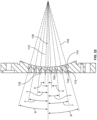
- the fill plate includes a plurality of holes through which food product is configured to pass, the holes being aligned in rows and columns such that a central row of holes is defined, each hole in the central row being formed by a straight wall extending from the inlet surface of the fill plate and a tapered wall extending from an outlet end of the straight wall to the outlet surface of the fill plate and a central axis of the straight wall and a central axis of the tapered wall are aligned with each other; and each hole in rows other than the central row being formed by a straight wall extending from the inlet surface of the fill plate and a tapered wall extending from an outlet end of the straight wall to the outlet surface of the fill plate and a central axis of the straight wall and a central axis of the tapered wall are angled relative to each other at an angle.
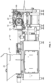
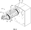
- FIGS. 1 and 2 illustrate the primary components of an embodiment of a rotary molding system 20 configured for use in a patty forming machine 22.
- the patty forming machine 22 includes a feeder portion 24 which supplies food product to the rotary molding system 20.
- the feeder portion 24 is formed from a hopper 25 connected to a pump box 26 by an auger system connected to a pump intake passage, a motor driven rotary pump, and a pump output passage (not shown).
- Such a feeder portion is disclosed in U.S. Patent No. 8,469,697 ,
- the pump box 26 may include a housing 28 and an insert 30 inserted within a chamber 32 in the housing 28.
- a cavity is formed therebetween.
- the position of the insert 30 may be adjusted relative to the housing 28 in order to vary the size of the cavity therebetween.
- the housing 28 has at least one feed opening 34 and the insert 30 has at least one feed opening 36 to channel food product from the hopper 25 through the pump box 26.
- the feed openings 34, 36 may be aligned.
- the pump box 26 is formed of a single component.
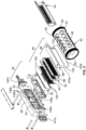
- the rotary molding system 20 includes a stationary support structure 38 which is attached to a cabinet 40 of the patty forming machine 22, a rotary hollow mold or drum 42 rotatably mounted on the support structure 38 by an inner platen 44, and a food channel assembly 46 which directs food product from the pump box 26 to the drum 42.
- the support structure 38 has an outer surface 38a and is cantilevered from the cabinet 40.
- the support structure 38 may be formed of steel.
- the support structure 38 can be supported on both ends.
- the support structure 38 is a mandrel.
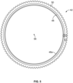
- the drum 42 is formed of a cylindrical wall 48 having an outer surface 48b and an inner surface 48a, and a toothed gear ring 50 extending about the circumference of the outer surface 48b of the wall 48 at each end thereof.
- a plurality of spaced apart mold cavities 52 are provided through the wall 48 and are disposed around the circumference of the wall 48.
- the wall 48 has a thickness which corresponds to the depth of the mold cavities 52.
- the number of mold cavities 52 around the circumference of the wall 48 can vary.
- the shape of the mold cavities 52 can vary.
- Structure 54 for rotating the drum 42 around the support structure 38, such as driven toothed endless belts, are provided. Such a structure 54 for rotating the drum 42 is disclosed in U.S. Patent No. 8,469 697 .
- the drum 42 rotates about a central axis 56.
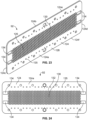
- the inner platen 44 is formed from a body 58 having a drum facing surface 58a and support structure engaging surface 58b defined by parallel side edges 58c, 58d and parallel end edges 58e, 58f. A length of the inner platen 44 is defined between the side edges 58c, 58d.
- the drum facing surface 58a is curved in accordance with the radius of curvature of the cylindrical drum 42.
- the support structure engaging surface 58b may be curved.
- the inner platen 44 may be formed of plastic.
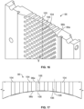
- the body 58 has a central perforated portion 60 with a non-perforated portion 62 extending around the perimeter of the central perforated portion 60 and between the central perforated portion 60 and the edges 58c, 58d, 58e, 58f.
- the central perforated portion 60 provides an air management system for allowing air to escape the mold cavities 52 as food product fills the mold cavities 52 and displaces the air in the mold cavities 52.
- the central perforated portion 60 includes an array of a plurality of distinct holes 64 which form rows and columns, a plurality of fins 66 separating columns of the holes 64 from each other and forming recesses 68 therebetween which are in communication with the holes 64, and an elongated opening 70 proximate to the fins 66.
- the fins 66 extend perpendicular to the axis of rotation of the drum 42 and partially between the end edges 58e, 58f.
- the fins 66 are curved in accordance with the radius of curvature of the drum 42.
- Each recess 68 may be formed of a first recess part 68a which extends between adjacent fins 66 and extends from the surface of the central perforated portion 60 and a plurality of second recess parts 68b which extend from the first recess part 68a.
- the second recess parts 68b are recessed further from the support structure engaging surface 58b than the respective first recess part 68a.
- the column of holes 64 may be in communication with the second recess part 68b.
- the columns of holes 64 may be transverse to the length of the body 58. In an embodiment, the holes 64 in alternating columns are aligned with each other. In an embodiment, the holes 64 have a diameter of 0.10 to 0.5 mm (0.04 to 0.06 inches).
- the holes 64 may be formed of a first smaller diameter portion 64a which extends from the drum facing surface 58a and a second larger diameter portion 64b which extends from the first portion to the second recess part 68b.
- the elongated opening 70 extends along a portion of the length of the body 58 and is proximate to the recesses 68 and is in communication with the recesses 68.
- a continuous recess 71 extends around the perimeter of the central perforated portion 60 into which an O-ring 72 is seated.
- the inner platen 44 is affixed to the support structure 38 by suitable means such as fasteners which extend through apertures 74 provided through the non-perforated portion 62.
- each roller mounting aperture 76 has a first section 76a which extends from the drum facing surface 58a of the inner platen 44, and a second section 76b which extends from the first section 76a to the support structure engaging surface 58b of the inner platen 44.
- the first section 76a has a dimension which is smaller than the second section 76b.
- the first and second sections 76a, 76b are rectangular.
- a drum roller support 78 is mounted within each roller mounting aperture 76 and supports an elongated cylindrical roller 80, see FIG. 12 .
- the drum roller support 78 is formed of a base wall 82 and a side wall 84 depending therefrom.
- the base wall 82 and the side wall 84 define an open-ended cavity 86.
- a pair of spaced apertures 88 are provided through the base wall 82 and are in communication with the cavity 86.
- the portion of the base wall 82 between the apertures 88 forms a curved race 82a.
- the base wall 82 extends outwardly of the side wall 84 and forms a flange 82b.
- the surface 82c opposite to the race 82a is planar.
- the surface 82c is curved. While the drum roller support 78 is described as a separate component, the drum roller support 78 may be integrally formed as part of the body 58 of the inner platen 44.
- the flange 82b of the drum roller support 78 seats within the second section 76b of the mounting aperture 76 and the side wall 84 seats within the first section 76a of the mounting aperture 76.
- the flange 82b corresponds in shape to the second section 76b and the side wall 84 corresponds in shape to the first section 76a so as to provide a secure fit between the drum roller support 78 and the inner platen 44.
- each roller 80 has a central cylindrical body section 80a and a reduced cylindrical end section 80b at both ends of the body section 80a.
- the body section 80a of each roller 80 is crowned to provide a self-aligning feature when the rollers 80 contact the inner surface of the drum 42 as described herein.
- the rollers 80 may be formed of plastic or metal.
- each roller 80 is about 5.08 cm (2 inches) long.
- the body section 80a of the roller 80 seats against the race 82a of the drum roller support 78.
- the body section 80a is wider than the cavity 86 such that the body section 80a partially protrudes outwardly from the side wall 84 of the drum roller support 78.
- each drum roller support 78 engages against the outer surface 38a of the support structure 38.
- the drum 42 is mounted on the inner platen 44 such that the drum facing surface 58a of the inner platen 44 is proximate to the inner surface 48a of the drum 42 and the rollers 80 engage the inner surface 48a of the drum 42.
- the drum 42 rotates around the inner platen 44 and the support structure 38.
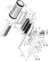
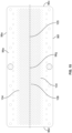
- the food channel assembly 46 includes a fill plate 90 which is proximate to the drum 42, a wear plate 92 fixedly attached to the fill plate 90, and a stripper plate 94 attached to the wear plate 92 and capable of movement relative to the wear plate 92, see FIGS. 3 and 4 .
- the food channel assembly 46 is attached to the housing 28 of the pump box 26.
- the fill plate 90 is formed of two parts, with an inner perforated body 96 which seats within an outer platen 98.
- the body 96 is formed of metal.
- the outer platen 98 if provided, is formed of plastic.
- the inner perforated body 96 has an inlet surface 96a and an outlet surface 96b defined by parallel side edges 96c, 96d and parallel end edges 96e, 96f.
- the body 96 has a centerline 96g which extends between the side edges 96c, 96d.
- the body 96 has a central perforated portion 100 with non-perforated portions 102 extending between the central perforated portion 100 and the end edges 96e, 96f.
- the inlet surface 96a is planar.
- the outlet surface 96b formed by the central perforated portion 100 is curved in accordance with the radius of curvature of the drum 42.
- the outlet surface 96b formed by the non-perforated portions 102 may be planar as shown, or may be curved in accordance with the radius of curvature of the drum 42.
- a length of the fill plate 90 is defined between the side edges 96c, 96d.
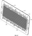
- An array of a plurality of distinct holes 104 are provided through the body 96 in the central perforated portion 100.
- the holes 104 in the fill plate 90 are aligned in rows and columns; the rows extending between the side edges 96c, 96d and the columns extending between end edges 96e, 96f.
- a central row 105 of holes 104 is formed along the centerline 96g of the body 96.
- the holes 104 in the fill plate 90 are randomly placed.
- the holes 104 in the fill plate 90 have a diameter of 6.35 to 11.11 mm (0.25 to 0.4375 inches).
- the fill plate 90 has an elongated feeder inlet passage (not shown) through which the food product passes to enter the mold cavities 52.
- An example of a curved fill plate 90 is shown in U.S. Patent No. 8 469 697 . Because of the shape of the fill plate 90, the fill plate 90 is an expensive component to make and can be an expensive component to properly maintain.
- each hole 104 is straight from the inlet surface 96a to the outlet surface 96b, that is each hole 104 has a uniform diameter along its length from the inlet surface 96a to the outlet surface 96b.
- the central axis 108 of each hole 104 is parallel to each other and is transverse to the centerline 96g of the body 96.
- each of the holes 104 in the array or predetermined ones of the holes 104 in the array have a straight wall 112 extending from the inlet surface 96a and a tapered or frustoconical wall 114 extending from the outlet end of the straight wall 112 to the outlet surface 96b.
- Each straight wall 112 has a uniform diameter along its length from the inlet surface 96a to the tapered or frustoconical wall 114.
- Each tapered or frustoconical wall 114 has its smallest diameter (which corresponds to the diameter of the straight wall 112) at its inlet end where tapered or frustoconical wall 114 joins with the straight wall 112 and has its largest diameter at its outlet end which is at the outlet surface 96b.
- the tapered or frustoconical wall 114 has a continuously increasing diameter as it extends along its length from its inlet end to its outlet end.
- the tapered or frustoconical wall 114 may extend along a small section of the length of the hole 104, along half or the length of the hole 104, or along almost the entire length of the hole 104.
- each hole 104 a central axis 116 of the straight wall 112 and a central axis 118 of the tapered or frustoconical wall 114 are aligned with each other.
- the central axis 116/118 of each hole 104 is parallel to each other and is transverse to the centerline 96g of the body 96.
- the length of the straight wall 112 increases as the rows move outwardly from the central row 105 of holes 104.
- all holes 104 in the central row 105 have a straight wall 112 extending from the inlet surface 96a and a tapered or frustoconical wall 114 extending from the outlet end of the straight wall 112 to the outlet surface 96b.
- Each straight wall 112 has a uniform diameter along its length from the inlet surface 96a to the tapered or frustoconical wall 114.
- Each tapered or frustoconical wall 114 has its smallest diameter (which corresponds to the diameter of the straight wall 112) at its inlet end where tapered or frustoconical wall 114 joins with the straight wall 112 and has its largest diameter at its outlet end which is at the outlet surface 96b.
- the tapered or frustoconical wall 114 has a continuously increasing diameter as it extends along its length from its inlet end to its outlet end.
- the tapered or frustoconical wall 114 may extend along a small section of the length of the hole 104, along half or the length of the hole 104, or along almost the entire length of the hole 104.
- the central axis 116 of the straight wall 112 and the central axis 118 of the tapered or frustoconical wall 114 are aligned with each other.
- the central axis 116/118 of each hole 104 in the central row 105 is aligned with each other and is transverse to the centerline 96g of the body 96.
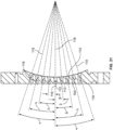
- the central axis 116 of the straight wall 112 and the central axis 118 of the tapered or frustoconical wall 114 of each hole 104 in the array which is offset from the central row 105 of holes 104 are at an angle to each other, and the tapered or frustoconical wall of each hole 104 is angled relative to the plane formed by the centerline 96g of the body 96.
- the holes 104 in the rows adjacent to the central row 105 are defined as the second rows; the holes 104 in the rows adjacent to the second rows are defined as the third rows; the holes 104 in the rows adjacent to the third rows are defined as the fourth rows; and so forth. As the rows progress outwardly from the central row 105, the angle increases.
- the holes 104 in the second row are angled at an angle ⁇ of 2.25 degrees relative to the centerline 96g; the holes 104 in the third row are angled at an angle ⁇ of 4.5 degrees relative to the centerline 96g; the holes 104 in the fourth row are angled at an angle ⁇ of 6.75 degrees relative to the centerline 96g; the holes 104 in the fifth row are angled at an angle ⁇ of 9 degrees relative to the centerline 96g; the holes 104 in the sixth row are angled at an angle ⁇ of 11.25 degrees relative to the centerline 96g; the holes 104 in the seventh row are angled at an angle ⁇ of 13.5 degrees relative to the centerline 96g; the holes 104 in the eight row are angled at an angle ⁇ of 15.75 degrees relative to the centerline 96g; the holes 104 in the ninth row are angled at an angle ⁇ of 18 degrees relative to the centerline 96g.
- More than or fewer than nine rows of holes 104 can be provided.
- the central axis 116 of the straight wall 112 of each hole 104 in the rows adjacent to the central row 105 is parallel to each other and is transverse to the centerline 96g. By angling the holes 104 which are not in the center row in this manner, the food product is directed to the middles of the mold cavities 52.
- the holes 104 in the central row 105 may be straight, that is, the holes 104 have a uniform diameter along its length.
- the holes 104 in the fill plate 90 may be a combination any of the types of holes 104 shown.
- the outlet surface 96b of the body 96 is in in close proximity to, but spaced from, the outer surface of the drum 42.
- the body 96 extends for a length which corresponds approximately to, or just slightly greater than, the distance spanned by the row of mold cavities 52 in the drum 42.
- a sealing mechanism or layer may be disposed on outlet surface of the body 96 to ensure adequate close contact with the drum 42 and to prevent food product from leaking from the mold cavities 52 once the mold cavities 52 are filled.
- the holes 64 in the inner platen 44 are offset from the holes 104 in the body 96.
- the body 96 has substantially more holes 104 than the number of holes 64 in the inner platen 44.
- the body 96 is mounted in outer platen 98 which forms a frame for the body 96.
- the outer platen 98 is formed from a body 120 having an inlet surface 120a which is planar and an outlet surface 120b which is curved in accordance with the radius of curvature of the drum 42.
- a passageway 122 is provided through the body 120 and extends from the inlet surface 120a to the outlet surface 120b.
- the body 96 seats within the passageway 122.
- the outer platen 98 is sandwiched between the pump box 26 and the drum 42, and is free floating relative to the pump box 26 and drum 42.
- the outer platen 98 is affixed to the housing 28 of the pump box 26 by suitable means such as bolts, and is spaced from the drum 42.
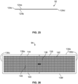
- the wear plate 92 is formed from a body 124 having a first surface 124a and a second surface 124b defined by parallel side edges 124c, 124d and parallel end edges 124e, 124f.
- the wear plate 92 is formed of metal.
- the first and second surfaces 124a, 124b are planar.
- a length of the wear plate 92 is defined between the side edges 124c, 124d.
- the body 124 has a central perforated portion 126 with a non-perforated portion 128 extending around the perimeter of the central perforated portion 126 and between the central perforated portion 126 and the edges 124c, 124d, 124e, 124f.
- An array of a plurality of distinct holes 130 are provided through the central perforated portion 126 of the body 124.
- the walls 132 forming the holes 130 are straight from the first surface 124a to the second surface 124b, that is each hole 130 has a uniform diameter along its length from the first surface 124a to the second surface 124b.
- the central axis of each hole 130 is parallel to each other.
- the holes 130 in the wear plate 92 have the same diameter as the holes 104 in the body 96.
- the holes 130 in the wear plate 92 have a diameter of 6.35 to 11.11 mm (0.25 to 0.4375 inches).
- the wear plate 92 has two pairs of recesses 134 in each surface 124a, 124b in the non-perforated portion 128 proximate to, but spaced from, the side edges 124c, 124d.
- the holes 130 in the wear plate 92 are aligned with the holes 104 in the body 96.
- the wear plate 92 has a plurality of apertures 135 through the non-perforated portion 128 proximate to, but spaced from, the end edges 124e, 124f.
- the wear plate 92 can be assembled with the body 96 with either the first surface 124a abutting against the body 96 or with the second surface 124b abutting against the body 96 as the wear plate 92 is identically formed on both surfaces 124a, 124b.
- the stripper plate 94 is disposed between the wear plate 92 and the pump box 26 and is capable of reciprocal movement relative to the wear plate 92 and the pump box 26.
- the stripper plate 94 is formed of metal.
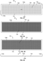
- the stripper plate 94 is formed from a body 136 having an inlet surface 136a and an outlet surface 136b defined by parallel side edges 136c, 136d and parallel end edges 136e, 136f.
- the inlet and outlet surfaces 136a, 136b are planar.
- a length of the stripper plate 94 is defined between the side edges 136c, 136d.
- the body 136 has a central perforated portion 138 with a non-perforated portion 140 extending around the perimeter of the central perforated portion 138 and between the central perforated portion 138 and the edges 136c, 136d, 136e, 136f.
- An array of a plurality of distinct holes 142 are provided through the central perforated portion 138 of the body. Each hole 142 in the array may be straight as it extends from the inlet surface 136a to the outlet surface 136b such that it has a uniform diameter along its length.
- Each of the holes 142 in the array or predetermined ones of the holes 142 in the array may have a tapered or frustoconical wall 144 extending from the inlet surface 136a and a straight wall 145 extending from the outlet end of the tapered or frustoconical wall 144 to the outlet surface 136b.
- the tapered or frustoconical wall 144 has its greatest diameter at its inlet end which is at the inlet surface 136a of the stripper plate 94 and has its smallest diameter at its outlet end which is at the junction of the tapered or frustoconical wall 144 and the straight wall 145.
- the tapered or frustoconical wall 144 has a continuously reducing diameter as it extends along its length from its inlet end to the outlet end.
- the straight wall 145 has a uniform diameter along its length.
- the holes 142 may be a combination of both types.
- the holes 142 in the stripper plate 94 are aligned in rows and columns.
- the holes 142 in the stripper plate 94 have the same diameter as the holes 104 in the body 96.
- the holes 142 in the stripper plate 94 have a diameter of 6.35 to 11.11 mm (0.25 to 0.4375 inches).
- the holes 142 in the stripper plate 94 are aligned in rows and columns and when assembled with the wear plate 92 and in the fill plate 90, the holes 142 in the stripper plate 94 are aligned with the holes 130 in the wear plate 92 and the holes 104 in the body 96 when in a first position, and when the stripper plate 94 is shifted, the holes 142 in the stripper plate 94 are offset from the holes 130 in the wear plate 92 and in the holes 104 in the body 96 when in a second position. This forms a seal off version of the stripper plate 94
- the number of holes 142 in the stripper plate 94 are doubled from the first embodiment to form a non-seal off version of the stripper plate 94.
- a first column of holes 142 is defined at the first end of the stripper plate 94 and a second column of holes 142 is defined next to the first column of holes 142.
- the first and second columns of holes 142 alternate along the length of the stripper plate 94.
- the stripper plate 94 When the stripper plate 94 is assembled with the wear plate 92 and in the fill plate 90, the first columns of holes 142 in the stripper plate 94 are aligned with the holes 130 in the wear plate 92 and in the holes 104 in the body 96 when in a first position, and when the stripper plate 94 is shifted, the second columns of holes 142 are aligned with the holes 130 in the wear plate 92 and in the holes 104 in the body 96 when in a second position.
- the stripper plate 94 is connected to the wear plate 92 by retainer bars 150 attached to the wear plate 92 see FIGS. 31 and 32 .
- the stripper plate was slidably attached to the fill plate by a plurality of spacers which had a thickness that is slightly greater than the thickness of the stripper plate and a plurality of bracket bars; the spacers and the bars being mounted by a plurality of fasteners.
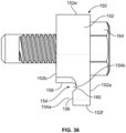
- each retainer bar 150 combines the two prior art components into a single retainer bar 150. As best shown in FIGS.
- the retainer bar 150 has an elongated body 152 having first and second surfaces 152a, 152b defined by parallel side edges 152c, 152d and parallel end edges 152e, 152f.
- a length is defined along the body 152 between the side edges 152c, 152d.
- a recess 154 is machined into the elongated body 152 along its length and has a first part 154a and a second part 154b.
- the first part 154a of the recess 154 is formed from a first planar wall 156 which extends from the end edge 152f and is offset from the second surface 152b and a second planar wall 158 which extends from the second surface 152b and is perpendicular to the first wall 156.
- the second part 154b is formed at the junction between the first and second walls 156, 158 and is form a curved wall 160.
- the curved wall 160 is offset from the second surface 152b at a greater distance than the first wall 156.
- the elongated body 152 has a plurality of spaced apart apertures 162 therethrough which will accept fasteners 164.
- the apertures 162 are offset from the recess 154.
- Each retainer bar 150 is attached to the wear plate 92 by a plurality of the fasteners 164 that extend through the apertures 162 and through the associated apertures 135 in the wear plate 92.
- the second surface 152b of each retainer bar 150 abuts against one of the surfaces 124a, 124b of the wear plate 92 (depending upon which way the wear plate 92 is used).
- the stripper plate 94 seats within the recesses 154 such that the edges 136e, 136f abut against the second wall 158, the inlet surface 136a abuts against the first wall 156 of the retainer bar 150, and the outlet surface 136b abuts against the first or second surface 124a, 124b of the wear plate 92 (depending upon which way the wear plate 92 is used).
- the stripper plate 94 and the wear plate 92 seat within the pump box 26.
- the stripper plate 94 is proximate to the feed openings 34, 36 in the pump box 26.
- the planar inlet surface 96a of the body 96 which forms the fill plate 90 seats against the first or second surface 124a, 124b of the wear plate 92 (depending upon which way the wear plate 92 is used). Thereafter, fasteners, such as bolts, are passed through the pump box 26, through the wear plate 92 and through the fill plate 90 to connect the pump box 26, the stripper plate 94, the wear plate 92 and the fill plate 90 together.
- two rods 146a, 146b have disk shaped heads 148 that are in contact with the side edges 136c, 136d of the stripper plate 94.
- the rods 146a, 146b extend through the side walls of the pump box housing 28 and are connected to respective first and second drive mechanisms 147a, 147b, such as hydraulic cylinders.
- the first drive mechanism 147a is activated to extend the rods 146a and move the stripper plate 94 in a first direction thereby causing the rods 146b to retract within the second drive mechanism 147b
- the second drive mechanism 147b is activated to extend the rods 146b and move the stripper plate 94 in a second, opposite direction thereby causing the rods 146a to retract within the first drive mechanism 147a. This is repeated to cause the stripper plate 94 to slide back and forth across the wear plate 92 in a reciprocating manner.
- the heads 148 of the rods 146 seat within the recesses 134 of the wear plate 92 to abut against the side edges 136c, 136d of the stripper plate 94 to sever any residual food product fibers which may be caught in the holes 130 of the wear plate 92 after each time the food product is passed through the holes 130 of the wear plate 92.
- the recesses 154 provide a running clearance to allow the stripper plate 94 to shift relative to the wear plate 92. The operation of the stripper plate 94 is discussed in further detail in U.S. application Ser. No. 11/408,248 , published as U.S. Patent Application Publication 2007/0098862 .
- the stripper plate 94 has been modified to include a pair of recess or apertures 170 into which the heads 148 of the rods 146 are seated.
- a pair of spaced apart apertures 170 are provided on surface 136a and on the same side of the stripper plate 94, for example, proximate to edge 136c.
- recesses may be provided on each surface of the stripper plate 94.
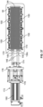
- Rods 146 extend through the same side wall of the pump box housing 28 and are connected to a single drive mechanism 172, such as an electric actuator or a hydraulic cylinder, by a coupler 174.
- the drive mechanism 172 is mounted on a stationary frame 176 connected to the pump box housing 28.
- the drive mechanism 172 includes a piston 178 which can be extended from a cylinder 180 or can be retracted into the cylinder 180.
- the piston 178 is coupled to the rods 146 by the coupler 174.
- the piston 178 of the drive mechanism 172 is linearly aligned with the rods 146.
- the drive mechanism 172 is activated to extend the piston 178 from the cylinder 180, thereby moving the rods 146 and the stripper plate 94 in a first direction relative to the wear plate 92, and thereafter the drive mechanism 172 is activated to retract the piston 178 into the cylinder 180, thereby moving the rods 146 and the stripper plate 94 in a second, opposite direction relative to the wear plate 92.
- This is repeated to cause the stripper plate 94 to slide back and forth across the wear plate 92 in a reciprocating manner to sever any residual food product fibers which may be caught in the holes 130 of the wear plate 92 after each time the food product is passed through the holes 130 of the wear plate 92.
- the recesses 134 in the wear plate 92 may be eliminated as recesses 134 are not used in this embodiment.
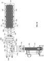
- the modified stripper plate 94 and the drive mechanism 172 of FIG. 37 are used and the specifics are not repeated.
- the rods 146 extend through a side wall of the pump box housing 28 and are connected to the single drive mechanism 172 by a coupling arrangement 182.
- the piston 178 of the drive mechanism 172 is not linearly aligned with the rods 146, and instead is perpendicular to the rods 146 as a result of the coupling arrangement 182.
- the coupling arrangement 182 includes a first link 184 having a first end 184a pivotally attached to the end 178a of the piston 178 and second end 184b pivotally attached to a stationary frame 176 connected to the pump box housing 28, a second link 186 having a first end 186a pivotally attached to the end 178a of the piston 178 and second end 186b pivotally attached to a first end 188a of a rod 188, the rod 188 extending through the stationary frame 176.
- the rod 188 and the second end 184b of the first link 184 may be linearly aligned.
- a second end 188b of the rod 188 is coupled to the rods 146 by the coupler 174.
- the drive mechanism 172 is activated to move the rods 146 and the stripper plate 94 in a first direction relative to the wear plate 92, and thereafter the drive mechanism 172 is activated to move the rods 146 and the stripper plate 94 in a second, opposite direction relative to the wear plate 92.
- the piston 178 is extended from the cylinder 180, the first ends 184a, 186a of the first and second links 184 move away from the cylinder 180 which causes the rod 188 to translate in a direction perpendicular to the piston 178 and toward the wear plate 92. This movement of the rod 188 causes movement of the rods 146 and then movement of the stripper plate 94 in the first direction.
- the first ends 184a, 186a of the first and second links 184 move toward the cylinder 180 which causes the rod 188 to translate in a direction perpendicular to the piston 178 and away from the wear plate 92.
- This movement of the rod 188 causes movement of the rods 146 and then movement of the stripper plate 94 in the second, opposite direction.
- the recesses 134 in the wear plate 92 may be eliminated as recesses 134 are not used in this embodiment.
- the rotary molding system 20 may include a knock-out mechanism 168 which is known in the art. Such a knock-out mechanism is disclosed in U.S. Patent No. 8,469,697 ,
- the mold cavities 52 rotate past the holes 104 in the fill plate 90.
- Food product is pumped from the hopper 25 to the rotary molding system 20 by the feeder portion 24.
- Food product passes through feed openings 34, 36 in the pump box 26, through the holes 142 in the stripper plate 94, through the holes 130 in the wear plate 92, and through the holes 104 in the body 96 to fill the mold cavities 52.
- any air within the mold cavities 52 is discharged via the air release passageway formed by the holes 64, the recesses 68 and the elongated opening 70 of the central perforated portion 60 of the inner platen 44.
- the mold cavities 52 are rotated from a fill position to an eject position where the knock-out mechanism 168 is activated.
- the stripper plate 94 shifts relative to the wear plate 92 from the first position to the second position, then back to the first position and then to the second position and so on. Because the stripper plate 94 shifts, the wear plate 92 may become worn.
- the wear plate 92 becomes worn on one surface, for example surface 124a
- the wear plate 92 is flipped over so that the surface 124b is in contact with the shifting stripper plate 94 (the retainer bars 150 are detached from the one surface and reattached to the other surface during this flipping).
- both surfaces 124a, 124b become worn, the wear plate 92 is replaced. Since the wear plate 92 is a planar plate with straight holes 130, this is a relatively inexpensive component to replace.
- the wear plate 92 is much less expensive to replace than replacing the curved body 96 which forms the fill plate 90.
- the drum facing surface 58a of the inner platen 44 is disposed in proximity to a portion of the inner surface 48b of the drum 42 with the rollers 80 engaging the inner surface 48b of the drum 42. Therefore, the drum 42 does not rub against the entire surface of the inner platen 44 and instead the drum 42 is only in contact with the rollers 80. This decreases the motor amperage required to rotate the drum 42.
- the mold cavities 52 in the drum 42 become disposed between the fill plate body 96 and the inner platen 44, with the drum facing surface 58a of the inner platen 44 serving as the bottom surface of the mold cavities 52 as the mold cavities 52 rotate through the region where it is in contact with the fill plate body 96 and the inner platen 44.
- the rollers 80 allow for the free rotation of the drum 42 relative to the inner platen 44.
- the inner platen 44 remains stationary as the drum 42 rotates past the inner platen 44.
- the support structure 38 behind the inner platen 44 provides support for the inner platen 44 as pressure from filling the mold cavities 52 is exerted into the mold cavities 52 during the filling process.
- the rotary molding system 20 can be pivoted relative to the cabinet 40 as is known in the art, U.S. Patent No. 8,469,697 .
- a sensor 166 such as a proximity sensor or an ultrasonic sensor, may be provided on the cabinet 40 to monitor the position of the rods 146 to ensure that the rods 146 are retracted before pivoting.
- the sensor 166 is in communication with a control system (not shown) which is used to alert an operator if the rods 146 are not properly retracted. This aids in deterring damage to the rotary molding system 20.
Landscapes
- Engineering & Computer Science (AREA)
- Food Science & Technology (AREA)
- Life Sciences & Earth Sciences (AREA)
- Mechanical Engineering (AREA)
- Wood Science & Technology (AREA)
- Zoology (AREA)
- Processing Of Meat And Fish (AREA)
- Formation And Processing Of Food Products (AREA)
- Manufacturing And Processing Devices For Dough (AREA)
Claims (12)
- Rotationsformsystem, konfiguriert zum Formen von Nahrungsmittelprodukten, Folgendes umfassend:eine Abstreifplatte (94) mit einer Einlassfläche (136a) und einer Auslassfläche (136b), wobei die Einlassfläche (136a) mit einer Zufuhrquelle in Verbindung steht, wobei die Abstreifplatte (94) eine Vielzahl von Durchgangslöchern (142) aufweist, durch die das Lebensmittelprodukt hindurchzugehen konfiguriert ist;eine Verschleißplatte (92) mit einer ebenen ersten Oberfläche (124a) und einer ebenen zweiten Oberfläche (124b), wobei die erste Oberfläche (124a) der Verschleißplatte (92) an der Auslassoberfläche (136b) der Abstreifplatte (94) anliegt, wobei die Abstreifplatte (94) in der Lage ist, sich in Bezug auf die Verschleißplatte (92) hin- und herzubewegen, wobei die Verschleißplatte (92) eine Vielzahl von Durchgangslöchern (130) aufweist, durch die das Lebensmittelprodukt hindurchzugehen konfiguriert ist;eine Füllplatte (90) mit einer Einlassfläche (96a) und einer Auslassfläche (96b), wobei die Einlassfläche (96a) der Füllplatte (90) an der zweiten Fläche (124b) der Verschleißplatte (92) anliegt, wobei die Füllplatte (90) eine Vielzahl von Durchgangslöchern (104) aufweist, durch die das Lebensmittelprodukt hindurchzugehen konfiguriert ist, wobei die Verschleißplatte (92) lösbar an der Füllplatte (90) befestigt ist; undeine zylindrische Trommel (42), die eine Innenoberfläche (48a), eine Außenoberfläche (48b) und Formhohlräume (52) aufweist, in die das Lebensmittelprodukt abgelagert zu werden konfiguriert ist, wobei die Außenoberfläche (48b) der Trommel (42) in der Nähe der Auslassoberfläche der Füllplatte (90) liegt; undwobei die Verschleißplatte (92) durch eine Vielzahl von Haltestangen (150) lösbar an der Abstreifplatte (94) befestigt ist und wobei jede Haltestange (150) eine Aussparung (154) definiert, in der die Abstreifplatte (94) sitzt, wobei die Abstreifplatte (94) in Bezug auf die Haltestangen (150) entfernt werden kann.
- Rotationsformsystem nach Anspruch 1, wobei die Auslassfläche (96b) der Füllplatte (90) gekrümmt ist.
- Rotationsformsystem nach Anspruch 1, wobei die Einlass- und Auslassflächen (136a, 136b) der Abstreifplatte (94) eben sind.
- Rotationsformsystem nach Anspruch 1, wobei jede Haltestange (150) einen ersten Aussparungsteil (154a) und einen zweiten Aussparungsteil (154b) einschließt, der mit dem ersten Aussparungsteil (154a) in Verbindung steht, wobei der erste Aussparungsteil (154a) durch ein Paar ebener Wände (156, 158) definiert ist, wobei der zweite Aussparungsteil (154b) durch eine gekrümmte Wand (160) definiert ist, wobei die Abstreifplatte (94) innerhalb des ersten Aussparungsteils (154a) sitzt.
- Rotationsformsystem nach Anspruch 1, wobei jede Haltestange (150) lösbar an der Verschleißplatte (92) befestigt ist.
- Rotationsformsystem nach Anspruch 1, ferner umfassend eine innere Platte (44), die innerhalb der Trommel (42) montiert ist, wobei die Platte (44) einen Körper (58) mit einer Vielzahl von Durchgangslöchern (64) umfasst, die mit den Formhohlräumen (52) in Verbindung stehen.
- Rotationsformsystem nach Anspruch 6, wobei die Platte (44) eine Vielzahl von Rippen (66) umfasst, die sich mit Aussparungen (68) abwechseln, wobei die Aussparungen (68) in Fluidverbindung mit den Löchern (64) stehen.
- Rotationsformsystem nach Anspruch 1, wobei die Abstreifplatte (94) doppelt so viele Löcher (142) aufweist wie die Verschleißplatte (92).
- Rotationsformsystem nach Anspruch 1, wobei jedes Loch (104) in der Füllplatte (90) durch eine Wand (106) gebildet wird, die sich von der Einlassfläche (96a) zur Auslassfläche (96b) erstreckt, die eine Länge definiert, wobei jedes Loch (104) einen einheitlichen Durchmesser entlang seiner Länge aufweist.
- Rotationsformsystem nach Anspruch 1, wobei die Vielzahl von Löchern (104) in der Füllplatte (90) durch eine gerade Wand (112), die sich von der Einlassfläche (96a) der Füllplatte (90) erstreckt, und eine sich verjüngende Wand (114) gebildet wird, die sich von einem Auslassende der geraden Wand (112) zu der Auslassfläche (96b) der Füllplatte (90) erstreckt, wobei eine Mittelachse (116) der geraden Wand (112) und eine Mittelachse (118) der sich verjüngenden Wand (114) miteinander ausgefluchtet sind.
- Rotationsformsystem nach Anspruch 1,wobei die Löcher (104) in der Füllplatte (90) in Reihen und Spalten ausgefluchtet sind, sodass eine mittlere Reihe (105) von Löchern (104) in der Füllplatte (90) definiert ist,wobei jedes Loch 9104) in der mittleren Reihe (105) durch eine gerade Wand (112), die sich von der Einlassfläche (96a) der Füllplatte (90) erstreckt, und eine sich verjüngende Wand (114), die sich von einem Auslassende der geraden Wand (112) zur Auslassfläche (96b) der Füllplatte (90) erstreckt, gebildet ist und eine Mittelachse (116) der geraden Wand (112) und eine Mittelachse (118) der sich verjüngenden Wand (114) miteinander ausgefluchtet sind; undwobei jedes Loch (104) in anderen Reihen als der mittleren Reihe (105) durch eine gerade Wand (112), die sich von der Einlassfläche (96a) der Füllplatte (90) erstreckt, und eine sich verjüngende Wand (114), die sich von einem Auslassende der geraden Wand (112) zur Auslassfläche (96b) der Füllplatte (90) erstreckt, gebildet wird und eine Mittelachse (116) der geraden Wand (112) und eine Mittelachse (118) der sich verjüngenden Wand (114) in einem Winkel in Bezug aufeinander geneigt sind.
- Rotationsformsystem nach Anspruch 11,wobei die Löcher (104) in den an die Mittelreihe (105) angrenzenden Reihen als die zweiten Reihen definiert sind; die Löcher (104) in den an die zweiten Reihen angrenzenden Reihen als die dritten Reihen definiert sind; undwobei sich der Winkel in dem Maße vergrößert, in dem die Lochreihen (104) von der mittleren Reihe (105) auswärts fortschreiten.
Priority Applications (1)
| Application Number | Priority Date | Filing Date | Title |
|---|---|---|---|
| EP24206051.5A EP4467043A3 (de) | 2016-10-20 | 2017-10-19 | Rotierendes formsystem |
Applications Claiming Priority (2)
| Application Number | Priority Date | Filing Date | Title |
|---|---|---|---|
| US201662410571P | 2016-10-20 | 2016-10-20 | |
| PCT/US2017/057407 WO2018075781A1 (en) | 2016-10-20 | 2017-10-19 | Rotary molding system |
Related Child Applications (1)
| Application Number | Title | Priority Date | Filing Date |
|---|---|---|---|
| EP24206051.5A Division EP4467043A3 (de) | 2016-10-20 | 2017-10-19 | Rotierendes formsystem |
Publications (3)
| Publication Number | Publication Date |
|---|---|
| EP3528636A1 EP3528636A1 (de) | 2019-08-28 |
| EP3528636A4 EP3528636A4 (de) | 2020-09-09 |
| EP3528636B1 true EP3528636B1 (de) | 2024-10-16 |
Family
ID=61971649
Family Applications (2)
| Application Number | Title | Priority Date | Filing Date |
|---|---|---|---|
| EP17861543.1A Active EP3528636B1 (de) | 2016-10-20 | 2017-10-19 | Rotierendes formsystem |
| EP24206051.5A Pending EP4467043A3 (de) | 2016-10-20 | 2017-10-19 | Rotierendes formsystem |
Family Applications After (1)
| Application Number | Title | Priority Date | Filing Date |
|---|---|---|---|
| EP24206051.5A Pending EP4467043A3 (de) | 2016-10-20 | 2017-10-19 | Rotierendes formsystem |
Country Status (3)
| Country | Link |
|---|---|
| US (2) | US10842322B2 (de) |
| EP (2) | EP3528636B1 (de) |
| WO (1) | WO2018075781A1 (de) |
Families Citing this family (5)
| Publication number | Priority date | Publication date | Assignee | Title |
|---|---|---|---|---|
| PL3612032T3 (pl) * | 2017-04-19 | 2021-07-19 | Gea Food Solutions Bakel B.V. | Ulepszone wnęki dezaeracji w członie formy |
| CN108450496A (zh) * | 2018-03-13 | 2018-08-28 | 冯复都 | 烤炉用多功能架 |
| NL2025218B1 (en) * | 2020-03-26 | 2021-10-20 | Marel Further Proc Bv | System for moulding comprising a mould member, a method for moulding and a method for configuring a mould member |
| NL2025770B1 (en) * | 2020-06-08 | 2022-01-28 | Marel Further Proc Bv | A rotary mould drum system configured for use in an installation for moulding food products from a pumpable foodmass |
| US12090517B2 (en) * | 2022-06-30 | 2024-09-17 | Provisur Technologies, Inc. | Separation machine having powered separator gap control |
Citations (2)
| Publication number | Priority date | Publication date | Assignee | Title |
|---|---|---|---|---|
| US20070098862A1 (en) * | 2005-04-22 | 2007-05-03 | Formax, Inc. | Angled fill ports and seal-off arrangement for patty-forming apparatus |
| WO2015012690A2 (en) * | 2013-07-25 | 2015-01-29 | Marel Townsend Further Processing B.V. | Moulding food products from a pumpable foodstuff mass |
Family Cites Families (52)
| Publication number | Priority date | Publication date | Assignee | Title |
|---|---|---|---|---|
| US1545266A (en) | 1924-08-15 | 1925-07-07 | Int Cork Co | Process of and apparatus for making cork articles |
| US3427649A (en) | 1966-09-12 | 1969-02-11 | Rudolph J Fay | Method and apparatus for producing shaped articles |
| US3581617A (en) * | 1968-02-13 | 1971-06-01 | Packaging Ind Inc | Roller die cutting machine or the like |
| US3711911A (en) * | 1970-11-25 | 1973-01-23 | Textron Inc | Method of roller bearing retention and assembly |
| US3768228A (en) | 1971-10-27 | 1973-10-30 | Doering C & Son Inc | Butter patty printer and packaging apparatus |
| US3813846A (en) | 1971-10-27 | 1974-06-04 | Doering & Son Inc C | Method and apparatus for sealing thermoplastic covers to trays |
| US3887964A (en) | 1972-01-24 | 1975-06-10 | Formax Inc | Food patty molding machine |
| US3851355A (en) | 1973-02-28 | 1974-12-03 | Hughes A Co Inc | Continuous meat forming apparatus |
| US4054967A (en) | 1975-10-20 | 1977-10-25 | Formax, Inc. | Food patty molding machine |
| US4298326A (en) | 1976-07-14 | 1981-11-03 | Armour And Company | Molding apparatus |
| US4118831A (en) | 1977-08-01 | 1978-10-10 | Hollymatic Corporation | Molding device |
| ES473307A1 (es) | 1977-09-14 | 1979-10-16 | Tivet Dev Ltd | Un metodo de preparar un producto carnico o similar a carne en molde |
| US4182003A (en) | 1978-02-28 | 1980-01-08 | Formax, Inc. | Food patty molding machine |
| US4284973A (en) | 1978-03-22 | 1981-08-18 | Howell Steven G | Vehicle alarm system |
| US4212609A (en) | 1978-05-17 | 1980-07-15 | Fay Rudolph J | Method and apparatus for producing shaped and sized food articles |
| US4193167A (en) | 1978-11-09 | 1980-03-18 | Armour And Company | Apparatus for molding meat patties |
| US4276318A (en) | 1978-11-09 | 1981-06-30 | Armour And Company | Apparatus and method for molding meat patties |
| US4356595A (en) | 1980-11-07 | 1982-11-02 | Formax, Inc. | Method and apparatus for molding food patties |
| FR2538223B1 (fr) | 1982-12-27 | 1988-03-04 | Tiffon Terrade Franck | Appareil de conditionnement de produits pateux, notamment de produits alimentaires, tels que de la viande hachee |
| US4646385A (en) | 1985-02-04 | 1987-03-03 | C. D. Briddell Inc. | Methods and apparatus for forming loose meat into lumps |
| CA1204262A (en) | 1985-08-16 | 1986-05-13 | James S. Sheffield | Injection mold apparatus with gas ejection |
| US4768260A (en) | 1987-10-07 | 1988-09-06 | Alfa-Laval Ab | Food patty molding machine |
| US4957425A (en) | 1989-05-15 | 1990-09-18 | Fay Rudolph J | Apparatus for producing shaped products |
| US4975039A (en) | 1989-09-18 | 1990-12-04 | Dare Gary L | Food molding and portioning apparatus |
| JPH0568525A (ja) | 1991-09-12 | 1993-03-23 | Ajinomoto Co Inc | 立体成型食品の製造法 |
| US5297947A (en) | 1992-05-05 | 1994-03-29 | Tiefenthaler Machinery Co., Inc. | Rotary die moulding insert system |
| US5411390A (en) | 1993-11-15 | 1995-05-02 | Fay; Rudolph J. | Apparatus for producing shaped products |
| NL1010630C2 (nl) | 1998-11-23 | 2000-05-24 | Stork Pmt | Vormen. |
| GB2352205A (en) | 1999-06-28 | 2001-01-24 | Nestle Sa | Chilled roller for moulding a food product |
| US6572360B1 (en) | 2000-04-28 | 2003-06-03 | Golden State Foods Corporation | Food patty molding apparatus |
| US6517340B2 (en) | 2001-02-22 | 2003-02-11 | Formax, Inc. | Mold plate having multiple rows of cavities for food patty-molding apparatus |
| NL1020942C2 (nl) * | 2002-06-26 | 2003-12-30 | Stork Titan Bv | Vorminrichting. |
| US7335013B2 (en) | 2003-09-16 | 2008-02-26 | Formax, Inc. | Drive systems for a reciprocating mold plate patty-forming machine |
| US7264459B2 (en) | 2003-10-28 | 2007-09-04 | Patriot Universal Holdings, Llc. | Device for keeping a mold plate square, perpendicular and driving for a food product molding machine |
| NL1026171C2 (nl) | 2004-05-11 | 2005-11-14 | Stork Titan Bv | Vormen. |
| CN101819793B (zh) * | 2004-11-18 | 2012-09-05 | 日本电产三协株式会社 | 磁信息媒体记录再生装置 |
| DE102006007639A1 (de) | 2006-02-18 | 2007-08-23 | Mht Mold & Hotrunner Technology Ag | Aufnahmesystem |
| US7775790B2 (en) | 2007-01-23 | 2010-08-17 | Formax, Inc. | Food molding mechanism for a food patty molding machine |
| US8029266B2 (en) | 2007-11-28 | 2011-10-04 | Stork Titan B.V. | Mould member for moulding three-dimensional products, system and methods of manufacturing a mould member |
| US7931461B2 (en) | 2007-11-28 | 2011-04-26 | Stork Titan B.V. | Mould member for moulding three-dimensional products, system and methods of manufacturing a mould member |
| US8613615B2 (en) | 2010-07-20 | 2013-12-24 | Formax, Inc. | Patty-forming apparatus with bottom feed and rotary pump |
| US8801427B2 (en) | 2010-07-20 | 2014-08-12 | Formax, Inc. | Patty-forming apparatus with top feed and rotary pump |
| US8469697B2 (en) | 2010-07-20 | 2013-06-25 | Formax, Inc. | Rotary mold system for molding food products |
| EP2449893B1 (de) | 2010-11-04 | 2016-08-17 | GEA Food Solutions Bakel B.V. | Masseverteilungsvorrichtung und Formvorrichtung |
| ES2541841T3 (es) * | 2011-01-25 | 2015-07-27 | Gea Food Solutions Bakel B.V. | Cadena de producción de alimentos |
| NL2006841C2 (nl) | 2011-05-24 | 2012-11-27 | Marel Townsend Further Proc Bv | Vorminrichting, alsmede werkwijze voor het vormen van een voedingsproduct. |
| CA2841854C (en) | 2011-07-25 | 2017-08-22 | Gea Food Solutions Bakel B.V. | Food forming apparatus with a food feed member |
| WO2013115647A1 (en) | 2012-02-03 | 2013-08-08 | Marel Townsend Further Processing B.V. | Moulding food products from a pumpable foodstuff mass |
| NL2013121B1 (en) * | 2014-07-04 | 2016-09-20 | Marel Townsend Further Proc Bv | Method for producing a cylindrical mould member for moulding three-dimensional products from a mass of one or more food starting materials. |
| EP3264902A4 (de) | 2015-03-05 | 2018-11-07 | Provisur Technologies, Inc. | Bratlingformmaschine mit kolben mit unterer zuführung und unterer befüllung |
| US10306913B2 (en) | 2016-02-04 | 2019-06-04 | Provisur Technologies, Inc. | Fill plate |
| EP3558010B1 (de) | 2016-12-21 | 2021-06-23 | Marel Further Processing B.V. | Vorrichtung und verfahren zum formen von nahrungsmitteln aus einer pumpfähiger nahrungsmittelmasse |
-
2017
- 2017-10-19 EP EP17861543.1A patent/EP3528636B1/de active Active
- 2017-10-19 EP EP24206051.5A patent/EP4467043A3/de active Pending
- 2017-10-19 US US15/788,397 patent/US10842322B2/en active Active
- 2017-10-19 WO PCT/US2017/057407 patent/WO2018075781A1/en not_active Ceased
-
2020
- 2020-09-04 US US17/012,453 patent/US11925299B2/en active Active
Patent Citations (2)
| Publication number | Priority date | Publication date | Assignee | Title |
|---|---|---|---|---|
| US20070098862A1 (en) * | 2005-04-22 | 2007-05-03 | Formax, Inc. | Angled fill ports and seal-off arrangement for patty-forming apparatus |
| WO2015012690A2 (en) * | 2013-07-25 | 2015-01-29 | Marel Townsend Further Processing B.V. | Moulding food products from a pumpable foodstuff mass |
Also Published As
| Publication number | Publication date |
|---|---|
| US20180110375A1 (en) | 2018-04-26 |
| EP3528636A1 (de) | 2019-08-28 |
| EP3528636A4 (de) | 2020-09-09 |
| US10842322B2 (en) | 2020-11-24 |
| EP4467043A3 (de) | 2025-02-12 |
| EP4467043A2 (de) | 2024-11-27 |
| WO2018075781A1 (en) | 2018-04-26 |
| US20200397191A1 (en) | 2020-12-24 |
| US11925299B2 (en) | 2024-03-12 |
Similar Documents
| Publication | Publication Date | Title |
|---|---|---|
| EP3528636B1 (de) | Rotierendes formsystem | |
| CN106259809B (zh) | 物质分配装置以及模制装置 | |
| US7125245B2 (en) | Tube valve arrangement for a patty-forming machine | |
| US3851355A (en) | Continuous meat forming apparatus | |
| US8469697B2 (en) | Rotary mold system for molding food products | |
| CA2645290C (en) | Mould member for moulding three-dimensional products, system and methods of manufacturing a mould member | |
| US8029266B2 (en) | Mould member for moulding three-dimensional products, system and methods of manufacturing a mould member | |
| NL2018036B1 (en) | Installations and methods for moulding food products with a pressurized air food product ejection system from a mould drum | |
| US11678675B2 (en) | Sensor system for patty forming machine and method of use | |
| NL2025218B1 (en) | System for moulding comprising a mould member, a method for moulding and a method for configuring a mould member | |
| NL2025209B1 (en) | Mould drum, system and method for moulding and a method for configuring a mould drum |
Legal Events
| Date | Code | Title | Description |
|---|---|---|---|
| STAA | Information on the status of an ep patent application or granted ep patent |
Free format text: STATUS: THE INTERNATIONAL PUBLICATION HAS BEEN MADE |
|
| PUAI | Public reference made under article 153(3) epc to a published international application that has entered the european phase |
Free format text: ORIGINAL CODE: 0009012 |
|
| STAA | Information on the status of an ep patent application or granted ep patent |
Free format text: STATUS: REQUEST FOR EXAMINATION WAS MADE |
|
| 17P | Request for examination filed |
Effective date: 20190508 |
|
| AK | Designated contracting states |
Kind code of ref document: A1 Designated state(s): AL AT BE BG CH CY CZ DE DK EE ES FI FR GB GR HR HU IE IS IT LI LT LU LV MC MK MT NL NO PL PT RO RS SE SI SK SM TR |
|
| AX | Request for extension of the european patent |
Extension state: BA ME |
|
| DAV | Request for validation of the european patent (deleted) | ||
| DAX | Request for extension of the european patent (deleted) | ||
| A4 | Supplementary search report drawn up and despatched |
Effective date: 20200812 |
|
| RIC1 | Information provided on ipc code assigned before grant |
Ipc: B29C 45/26 20060101ALI20200806BHEP Ipc: B30B 11/12 20060101ALI20200806BHEP Ipc: A23P 30/10 20160101ALI20200806BHEP Ipc: A22C 7/00 20060101AFI20200806BHEP |
|
| STAA | Information on the status of an ep patent application or granted ep patent |
Free format text: STATUS: EXAMINATION IS IN PROGRESS |
|
| 17Q | First examination report despatched |
Effective date: 20221013 |
|
| P01 | Opt-out of the competence of the unified patent court (upc) registered |
Effective date: 20230524 |
|
| RIC1 | Information provided on ipc code assigned before grant |
Ipc: A47J 43/20 20060101ALI20240228BHEP Ipc: B30B 11/12 20060101ALI20240228BHEP Ipc: B29C 45/26 20060101ALI20240228BHEP Ipc: A23P 30/10 20160101ALI20240228BHEP Ipc: A22C 7/00 20060101AFI20240228BHEP |
|
| GRAP | Despatch of communication of intention to grant a patent |
Free format text: ORIGINAL CODE: EPIDOSNIGR1 |
|
| STAA | Information on the status of an ep patent application or granted ep patent |
Free format text: STATUS: GRANT OF PATENT IS INTENDED |
|
| INTG | Intention to grant announced |
Effective date: 20240507 |
|
| GRAS | Grant fee paid |
Free format text: ORIGINAL CODE: EPIDOSNIGR3 |
|
| GRAA | (expected) grant |
Free format text: ORIGINAL CODE: 0009210 |
|
| STAA | Information on the status of an ep patent application or granted ep patent |
Free format text: STATUS: THE PATENT HAS BEEN GRANTED |
|
| AK | Designated contracting states |
Kind code of ref document: B1 Designated state(s): AL AT BE BG CH CY CZ DE DK EE ES FI FR GB GR HR HU IE IS IT LI LT LU LV MC MK MT NL NO PL PT RO RS SE SI SK SM TR |
|
| REG | Reference to a national code |
Ref country code: GB Ref legal event code: FG4D |
|
| REG | Reference to a national code |
Ref country code: CH Ref legal event code: EP Ref country code: DE Ref legal event code: R096 Ref document number: 602017085572 Country of ref document: DE |
|
| REG | Reference to a national code |
Ref country code: IE Ref legal event code: FG4D |
|
| REG | Reference to a national code |
Ref country code: NL Ref legal event code: FP |
|
| REG | Reference to a national code |
Ref country code: LT Ref legal event code: MG9D |
|
| REG | Reference to a national code |
Ref country code: AT Ref legal event code: MK05 Ref document number: 1732141 Country of ref document: AT Kind code of ref document: T Effective date: 20241016 |
|
| PG25 | Lapsed in a contracting state [announced via postgrant information from national office to epo] |
Ref country code: IS Free format text: LAPSE BECAUSE OF FAILURE TO SUBMIT A TRANSLATION OF THE DESCRIPTION OR TO PAY THE FEE WITHIN THE PRESCRIBED TIME-LIMIT Effective date: 20250216 Ref country code: PT Free format text: LAPSE BECAUSE OF FAILURE TO SUBMIT A TRANSLATION OF THE DESCRIPTION OR TO PAY THE FEE WITHIN THE PRESCRIBED TIME-LIMIT Effective date: 20250217 Ref country code: HR Free format text: LAPSE BECAUSE OF FAILURE TO SUBMIT A TRANSLATION OF THE DESCRIPTION OR TO PAY THE FEE WITHIN THE PRESCRIBED TIME-LIMIT Effective date: 20241016 |
|
| PGFP | Annual fee paid to national office [announced via postgrant information from national office to epo] |
Ref country code: DE Payment date: 20241227 Year of fee payment: 8 |
|
| PG25 | Lapsed in a contracting state [announced via postgrant information from national office to epo] |
Ref country code: FI Free format text: LAPSE BECAUSE OF FAILURE TO SUBMIT A TRANSLATION OF THE DESCRIPTION OR TO PAY THE FEE WITHIN THE PRESCRIBED TIME-LIMIT Effective date: 20241016 |
|
| PG25 | Lapsed in a contracting state [announced via postgrant information from national office to epo] |
Ref country code: BG Free format text: LAPSE BECAUSE OF FAILURE TO SUBMIT A TRANSLATION OF THE DESCRIPTION OR TO PAY THE FEE WITHIN THE PRESCRIBED TIME-LIMIT Effective date: 20241016 |
|
| PG25 | Lapsed in a contracting state [announced via postgrant information from national office to epo] |
Ref country code: ES Free format text: LAPSE BECAUSE OF FAILURE TO SUBMIT A TRANSLATION OF THE DESCRIPTION OR TO PAY THE FEE WITHIN THE PRESCRIBED TIME-LIMIT Effective date: 20241016 |
|
| PG25 | Lapsed in a contracting state [announced via postgrant information from national office to epo] |
Ref country code: NO Free format text: LAPSE BECAUSE OF FAILURE TO SUBMIT A TRANSLATION OF THE DESCRIPTION OR TO PAY THE FEE WITHIN THE PRESCRIBED TIME-LIMIT Effective date: 20250116 |
|
| PG25 | Lapsed in a contracting state [announced via postgrant information from national office to epo] |
Ref country code: AT Free format text: LAPSE BECAUSE OF FAILURE TO SUBMIT A TRANSLATION OF THE DESCRIPTION OR TO PAY THE FEE WITHIN THE PRESCRIBED TIME-LIMIT Effective date: 20241016 Ref country code: LV Free format text: LAPSE BECAUSE OF FAILURE TO SUBMIT A TRANSLATION OF THE DESCRIPTION OR TO PAY THE FEE WITHIN THE PRESCRIBED TIME-LIMIT Effective date: 20241016 Ref country code: GR Free format text: LAPSE BECAUSE OF FAILURE TO SUBMIT A TRANSLATION OF THE DESCRIPTION OR TO PAY THE FEE WITHIN THE PRESCRIBED TIME-LIMIT Effective date: 20250117 |
|
| PG25 | Lapsed in a contracting state [announced via postgrant information from national office to epo] |
Ref country code: PL Free format text: LAPSE BECAUSE OF FAILURE TO SUBMIT A TRANSLATION OF THE DESCRIPTION OR TO PAY THE FEE WITHIN THE PRESCRIBED TIME-LIMIT Effective date: 20241016 |
|
| PG25 | Lapsed in a contracting state [announced via postgrant information from national office to epo] |
Ref country code: RS Free format text: LAPSE BECAUSE OF FAILURE TO SUBMIT A TRANSLATION OF THE DESCRIPTION OR TO PAY THE FEE WITHIN THE PRESCRIBED TIME-LIMIT Effective date: 20250116 |
|
| REG | Reference to a national code |
Ref country code: CH Ref legal event code: PL |
|
| PG25 | Lapsed in a contracting state [announced via postgrant information from national office to epo] |
Ref country code: SM Free format text: LAPSE BECAUSE OF FAILURE TO SUBMIT A TRANSLATION OF THE DESCRIPTION OR TO PAY THE FEE WITHIN THE PRESCRIBED TIME-LIMIT Effective date: 20241016 |
|
| PG25 | Lapsed in a contracting state [announced via postgrant information from national office to epo] |
Ref country code: MC Free format text: LAPSE BECAUSE OF FAILURE TO SUBMIT A TRANSLATION OF THE DESCRIPTION OR TO PAY THE FEE WITHIN THE PRESCRIBED TIME-LIMIT Effective date: 20241016 |
|
| PG25 | Lapsed in a contracting state [announced via postgrant information from national office to epo] |
Ref country code: DK Free format text: LAPSE BECAUSE OF FAILURE TO SUBMIT A TRANSLATION OF THE DESCRIPTION OR TO PAY THE FEE WITHIN THE PRESCRIBED TIME-LIMIT Effective date: 20241016 |
|
| PG25 | Lapsed in a contracting state [announced via postgrant information from national office to epo] |
Ref country code: LU Free format text: LAPSE BECAUSE OF NON-PAYMENT OF DUE FEES Effective date: 20241019 Ref country code: BE Free format text: LAPSE BECAUSE OF NON-PAYMENT OF DUE FEES Effective date: 20241031 |
|
| REG | Reference to a national code |
Ref country code: DE Ref legal event code: R097 Ref document number: 602017085572 Country of ref document: DE |
|
| PG25 | Lapsed in a contracting state [announced via postgrant information from national office to epo] |
Ref country code: EE Free format text: LAPSE BECAUSE OF FAILURE TO SUBMIT A TRANSLATION OF THE DESCRIPTION OR TO PAY THE FEE WITHIN THE PRESCRIBED TIME-LIMIT Effective date: 20241016 |
|
| PG25 | Lapsed in a contracting state [announced via postgrant information from national office to epo] |
Ref country code: CH Free format text: LAPSE BECAUSE OF NON-PAYMENT OF DUE FEES Effective date: 20241031 |
|
| PG25 | Lapsed in a contracting state [announced via postgrant information from national office to epo] |
Ref country code: RO Free format text: LAPSE BECAUSE OF FAILURE TO SUBMIT A TRANSLATION OF THE DESCRIPTION OR TO PAY THE FEE WITHIN THE PRESCRIBED TIME-LIMIT Effective date: 20241016 |
|
| PG25 | Lapsed in a contracting state [announced via postgrant information from national office to epo] |
Ref country code: SK Free format text: LAPSE BECAUSE OF FAILURE TO SUBMIT A TRANSLATION OF THE DESCRIPTION OR TO PAY THE FEE WITHIN THE PRESCRIBED TIME-LIMIT Effective date: 20241016 |
|
| PG25 | Lapsed in a contracting state [announced via postgrant information from national office to epo] |
Ref country code: CZ Free format text: LAPSE BECAUSE OF FAILURE TO SUBMIT A TRANSLATION OF THE DESCRIPTION OR TO PAY THE FEE WITHIN THE PRESCRIBED TIME-LIMIT Effective date: 20241016 |
|
| PG25 | Lapsed in a contracting state [announced via postgrant information from national office to epo] |
Ref country code: IT Free format text: LAPSE BECAUSE OF FAILURE TO SUBMIT A TRANSLATION OF THE DESCRIPTION OR TO PAY THE FEE WITHIN THE PRESCRIBED TIME-LIMIT Effective date: 20241016 |
|
| REG | Reference to a national code |
Ref country code: BE Ref legal event code: MM Effective date: 20241031 |
|
| PLBE | No opposition filed within time limit |
Free format text: ORIGINAL CODE: 0009261 |
|
| STAA | Information on the status of an ep patent application or granted ep patent |
Free format text: STATUS: NO OPPOSITION FILED WITHIN TIME LIMIT |
|
| PG25 | Lapsed in a contracting state [announced via postgrant information from national office to epo] |
Ref country code: SE Free format text: LAPSE BECAUSE OF FAILURE TO SUBMIT A TRANSLATION OF THE DESCRIPTION OR TO PAY THE FEE WITHIN THE PRESCRIBED TIME-LIMIT Effective date: 20241016 |
|
| 26N | No opposition filed |
Effective date: 20250717 |
|
| GBPC | Gb: european patent ceased through non-payment of renewal fee |
Effective date: 20250116 |
|
| PG25 | Lapsed in a contracting state [announced via postgrant information from national office to epo] |
Ref country code: GB Free format text: LAPSE BECAUSE OF NON-PAYMENT OF DUE FEES Effective date: 20250116 |
|
| PG25 | Lapsed in a contracting state [announced via postgrant information from national office to epo] |
Ref country code: FR Free format text: LAPSE BECAUSE OF NON-PAYMENT OF DUE FEES Effective date: 20241216 |
|
| PG25 | Lapsed in a contracting state [announced via postgrant information from national office to epo] |
Ref country code: IE Free format text: LAPSE BECAUSE OF NON-PAYMENT OF DUE FEES Effective date: 20241019 |
|
| PGFP | Annual fee paid to national office [announced via postgrant information from national office to epo] |
Ref country code: NL Payment date: 20251026 Year of fee payment: 9 |