EP3528566B1 - Procédé, appareil et système de transmission de données de réseau sans fil - Google Patents
Procédé, appareil et système de transmission de données de réseau sans fil Download PDFInfo
- Publication number
- EP3528566B1 EP3528566B1 EP16920797.4A EP16920797A EP3528566B1 EP 3528566 B1 EP3528566 B1 EP 3528566B1 EP 16920797 A EP16920797 A EP 16920797A EP 3528566 B1 EP3528566 B1 EP 3528566B1
- Authority
- EP
- European Patent Office
- Prior art keywords
- data
- terminal device
- sidelink logical
- identifier
- logical channel
- Prior art date
- Legal status (The legal status is an assumption and is not a legal conclusion. Google has not performed a legal analysis and makes no representation as to the accuracy of the status listed.)
- Active
Links
- 230000005540 biological transmission Effects 0.000 title claims description 343
- 238000000034 method Methods 0.000 title claims description 42
- 238000012545 processing Methods 0.000 claims description 86
- 238000004891 communication Methods 0.000 claims description 44
- 238000013507 mapping Methods 0.000 claims description 15
- 230000006870 function Effects 0.000 description 28
- 238000010586 diagram Methods 0.000 description 13
- 230000015654 memory Effects 0.000 description 11
- 238000004590 computer program Methods 0.000 description 4
- 238000013461 design Methods 0.000 description 4
- 238000005516 engineering process Methods 0.000 description 3
- 230000003287 optical effect Effects 0.000 description 2
- 230000011664 signaling Effects 0.000 description 2
- 230000001413 cellular effect Effects 0.000 description 1
- 230000001419 dependent effect Effects 0.000 description 1
- 230000003993 interaction Effects 0.000 description 1
- 230000007774 longterm Effects 0.000 description 1
- 238000005259 measurement Methods 0.000 description 1
- 238000010295 mobile communication Methods 0.000 description 1
- 239000013307 optical fiber Substances 0.000 description 1
- 238000010561 standard procedure Methods 0.000 description 1
Images


Classifications
-
- H—ELECTRICITY
- H04—ELECTRIC COMMUNICATION TECHNIQUE
- H04W—WIRELESS COMMUNICATION NETWORKS
- H04W72/00—Local resource management
- H04W72/04—Wireless resource allocation
- H04W72/044—Wireless resource allocation based on the type of the allocated resource
- H04W72/0473—Wireless resource allocation based on the type of the allocated resource the resource being transmission power
-
- H—ELECTRICITY
- H04—ELECTRIC COMMUNICATION TECHNIQUE
- H04W—WIRELESS COMMUNICATION NETWORKS
- H04W76/00—Connection management
- H04W76/10—Connection setup
- H04W76/14—Direct-mode setup
-
- H—ELECTRICITY
- H04—ELECTRIC COMMUNICATION TECHNIQUE
- H04W—WIRELESS COMMUNICATION NETWORKS
- H04W52/00—Power management, e.g. TPC [Transmission Power Control], power saving or power classes
- H04W52/04—TPC
- H04W52/30—TPC using constraints in the total amount of available transmission power
- H04W52/36—TPC using constraints in the total amount of available transmission power with a discrete range or set of values, e.g. step size, ramping or offsets
- H04W52/367—Power values between minimum and maximum limits, e.g. dynamic range
-
- H—ELECTRICITY
- H04—ELECTRIC COMMUNICATION TECHNIQUE
- H04W—WIRELESS COMMUNICATION NETWORKS
- H04W52/00—Power management, e.g. TPC [Transmission Power Control], power saving or power classes
- H04W52/04—TPC
- H04W52/38—TPC being performed in particular situations
- H04W52/383—TPC being performed in particular situations power control in peer-to-peer links
-
- H—ELECTRICITY
- H04—ELECTRIC COMMUNICATION TECHNIQUE
- H04W—WIRELESS COMMUNICATION NETWORKS
- H04W4/00—Services specially adapted for wireless communication networks; Facilities therefor
- H04W4/30—Services specially adapted for particular environments, situations or purposes
- H04W4/40—Services specially adapted for particular environments, situations or purposes for vehicles, e.g. vehicle-to-pedestrians [V2P]
-
- H—ELECTRICITY
- H04—ELECTRIC COMMUNICATION TECHNIQUE
- H04W—WIRELESS COMMUNICATION NETWORKS
- H04W52/00—Power management, e.g. TPC [Transmission Power Control], power saving or power classes
- H04W52/04—TPC
- H04W52/18—TPC being performed according to specific parameters
- H04W52/28—TPC being performed according to specific parameters using user profile, e.g. mobile speed, priority or network state, e.g. standby, idle or non transmission
- H04W52/281—TPC being performed according to specific parameters using user profile, e.g. mobile speed, priority or network state, e.g. standby, idle or non transmission taking into account user or data type priority
Definitions
- the present invention relates to wireless communications technologies, and in particular, to a method for data transmission in a wireless network and a terminal device.
- V2X is a wireless communications technology for data transmission and information exchange between a vehicle and everything.
- V2X communication includes vehicle to vehicle (V2V) communication, vehicle to infrastructure (V2I) communication, vehicle to pedestrian (V2P) communication, and the like.
- V2V vehicle to vehicle
- V2I vehicle to infrastructure
- V2P vehicle to pedestrian
- a vehicle may obtain rich information and services in time by performing V2X communication. This greatly improves intelligence of a transport system.
- a network used for V2X communication is referred to as the Internet of Vehicles.
- An LTE system may be used to carry various services in the Internet of Vehicles.
- a vehicle terminal device and another terminal device exchange V2X service data by using a V2X message.
- a transmission resource needs to be used when V2X service data is transmitted between terminal devices.
- a terminal device may use a transmission resource dynamically allocated by a network device, or may autonomously select a transmission resource from a transmission resource pool preconfigured by a network device. In the autonomous selection manner, a plurality of neighboring terminal devices may select a same transmission resource, that is, a transmission collision occurs. As a quantity of terminal devices or service density increases, a transmission collision rate also increases correspondingly.
- the terminal device In addition to V2X service data, the terminal device further needs to transmit service data of another type, for example, voice service data. To ensure transmission coverage of service data of various types, the terminal device needs to allocate appropriate transmit powers for service data of different types. However, there is an upper limit for a total transmit power configured by the system for the terminal device. Therefore, service data of a plurality of types that is simultaneously transmitted contends for an available transmit power. Consequently, a total transmit power does not satisfy a requirement, and further, some data cannot be transmitted to a specified receiving target device. In a high-density service scenario, insufficiency of transmission resources and transmit powers of the system has severe impact on transmission performance of the system. Huawei et al: "Support of QoS for PC5-based V2V transport", 3GPP Draft R2-163811 , refers to sildelink logical radio bearer and logical channel configuration.
- US 2013/0324182 A1 discusses device-to-device, D2D, cross link power control systems and methods.
- US 2016/0066356 A1 describes improved handling of simultaneous network communication transmission and D2D communication reception or simultaneous network communication reception and D2D communication transmission.
- the present invention as defined in the appended claims provides a method for data transmission in a wireless network and device to ensure efficient communication between terminal devices in a high-density service scenario, reduce impact of transmission resource insufficiency or transmit power insufficiency on system performance, and improve work performance of a system.
- the invention is defined by a method according to claim 1 and a terminal according to claim 6. Further embodiments are defined by the dependent
- the terminal device performs the transmission control operation on data on the first sidelink logical channel in a high-density service scenario. This ensures efficient communication between terminal devices, reduces impact of transmission resource insufficiency or transmit power insufficiency on system performance, and improves work performance of the system.
- the solutions provided by the implementations of the present disclosure are based on a communications system 100 shown in FIG. 1 .
- the communications system 100 supports V2X communication and other service communication (for example, a voice service).
- the communications system 100 includes at least one network device (for example, a base station (BS)) and a plurality of terminal devices (for example, vehicle terminal devices).
- the network device may provide data transmission services for the plurality of terminal devices.
- the plurality of terminal devices may exchange data by using V2X messages.
- V2V communication as an example, a vehicle terminal device may share, in real time by using a V2V message, information about the vehicle terminal device, such as a vehicle speed, a driving direction, a specific location, and whether to perform emergency braking or not.
- Other vehicle terminal devices may learn a current traffic condition by obtaining the shared information, to predetermine and avoid a possible danger.
- the plurality of terminal devices may further transmit data of other service types to each other, to implement diversified data exchange services.
- the terminal devices may transmit data (for example, a V2X message) to each other by using the network device.
- the terminal device first transmits to-be-transmitted data to the network device, and then the network device transmits the data to another terminal device (for example, as shown by dashed-line arrows in FIG. 1 ).
- the terminal devices may also transmit data to each other in a direct communication mode (for example, as shown by solid-line arrows in FIG. 1 ). In the direct communication mode, the terminal devices directly transmit data to each other by using resources allocated by the network device.
- the terminal device needs to use a transmission resource when transmitting data in the direct communication mode.
- the transmission resource may be a time-frequency resource.
- the transmission resource may be dynamically allocated by the network device. For example, the network device allocates an appropriate transmission resource to the terminal device based on an amount of the data to be transmitted by the terminal device.
- the network device may also configure a transmission resource pool for the terminal device in advance. When the terminal device is located outside a service area covered by the network device, the network device may also configure a transmission resource pool in a preconfiguration mode.
- the transmission resource pool is shared by the plurality of terminal devices. The terminal device may autonomously select a transmission resource from the transmission resource pool when the terminal device has a data transmission requirement.
- the terminal device may transmit service data of different types, for example, V2X service data and non-V2X service data.
- the terminal device needs to allocate transmit powers for data of various types, to ensure maximally efficient transmission.
- the communications system 100 includes a network device 10 and a plurality of terminal devices.
- the plurality of terminal devices may be identified as terminal devices 20A to 20C respectively.
- Data may be transmitted between the terminal devices 20A to 20C by using the network device 10, or data may be transmitted between the terminal devices 20A to 20C in a direct communication mode.
- the network device 10 may dynamically allocate transmission resources to the terminal devices 20A to 20C, or may preconfigure a transmission resource pool for the terminal devices 20A to 20C.
- the communications system 100 may be a Global System for Mobile Communications (GSM) system, a Code Division Multiple Access (CDMA) system, a Wideband Code Division Multiple Access (WCDMA) system, a general packet radio service (GPRS) system, a Long Term Evolution (LTE) system, an LTE frequency division duplex (FDD) system, an LTE time division duplex (TDD), a Universal Mobile Telecommunications System (UMTS), or another wireless communications system using an orthogonal frequency division multiplexing (OFDM) technology.
- GSM Global System for Mobile Communications
- CDMA Code Division Multiple Access
- WCDMA Wideband Code Division Multiple Access
- GPRS general packet radio service
- LTE Long Term Evolution
- FDD frequency division duplex
- TDD LTE time division duplex
- UMTS Universal Mobile Telecommunications System
- OFDM orthogonal frequency division multiplexing
- the network device may be configured to provide a wireless communication function for the terminal device.
- the network device may include a macro base station, a micro base station (also referred to as a small cell), a relay station, an access point, and the like in various forms.
- the network device may be a base transceiver station (BTS) in GSM or CDMA system, or may be a NodeB (NB) in WCDMA, or may be an evolved NodeB (eNB, or e-NodeB) in LTE system, or may be a corresponding next generation NodeB (gNB) in a 5G network.
- BTS base transceiver station
- NB NodeB
- eNB evolved NodeB
- gNB next generation NodeB
- the terminal device may also be referred to as user equipment (UE), a mobile station (MS), a mobile terminal (Mobile Terminal), or the like.
- the terminal device may communicate with one or more core networks by using a radio access network (RAN).
- RAN radio access network
- the terminal device may be a mobile phone (or referred to as a "cellular" phone), or a computer having a mobile terminal.
- the terminal device may alternatively be a portable, pocket-sized, handheld, computer built-in, or in-vehicle mobile apparatus, which exchanges voice and/or data with the network. This is not specifically limited in the implementations of the present disclosure.
- a quantity of network elements included in the communications system 100 shown in FIG. 1 is merely an example, and the implementations of the present disclosure are not limited thereto.
- the communications systems 100 may not be limited to including the foregoing network elements, the communications systems 100 may further include, for example, a device configured to bear a virtualized network function. Details are not described herein.
- the terminal device may autonomously select a transmission resource from a transmission resource pool configured in advance or preconfigured by the network device.
- a transmission resource that is, a transmission collision occurs. Consequently, a transmission channel is busy.
- impact of the busy transmission channel on system performance is relatively low.
- a transmission collision rate also increases correspondingly. Due to a higher transmission collision rate, some data on the transmission channel may not be transmitted normally.
- a transmission control operation is performed on first data on a first sidelink logical channel, to ensure reliable transmission of important data and improve work performance of a system.
- the method for data transmission in a wireless network according to this implementation of the present disclosure may be used to improve transmission performance of the system while ensuring data transmission reliability.
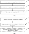
- FIG. 2 is a flowchart of a method for data transmission in a wireless network according to an implementation of the present disclosure.
- a terminal device may transmit service data of different types at a same time, for example, V2X service data and non-V2X service data. The method provided by this implementation is described in detail below with reference to FIG. 2 .
- a terminal device determines first configuration information.
- the first configuration information is used to determine at least one first sidelink logical channel.
- the first sidelink logical channel is used to transmit direct communication data.
- the first configuration information may be further used to determine a second sidelink logical channel.
- the second sidelink logical channel may also be used to transmit direct communication data. For example, both the first sidelink logical channel and the second sidelink logical channel may be used to transmit the V2X service data.
- the first configuration information includes at least one first identifier.
- the first identifier is used to determine the first sidelink logical channel.
- the first configuration information includes a first identifier list.
- the first configuration information includes one first identifier alone.
- the first identifier may correspond to at least one sidelink logical channel.
- the first identifier may be a logical channel identifier.
- the first identifier may alternatively be a priority identifier, for example, a PPPP (ProSe Per-Packet Priority) identifier or a quality of service class identifier (QCI).
- Each sidelink logical channel corresponds to one priority identifier.
- the priority identifier is used to indicate a transmission requirement or feature of data on the sidelink logical channel, for example, a priority of the data, a transmission latency requirement of the data, or a reference transmit power of the data.
- the first configuration information includes at least one second identifier. Similar to a case in which the first configuration information includes the first identifier, the first configuration information may include a second identifier list or one second identifier alone.
- the second identifier may correspond to at least one sidelink logical channel.
- the second identifier may be an identifier of a sidelink logical channel, or may be a priority identifier, for example, a PPPP identifier or a QCI.
- the first configuration information may further include both the first identifier and the second identifier.
- the first configuration information may include first indication information.
- the first indication information is used to indicate that some or all sidelink logical channels are the first sidelink logical channels.
- the terminal device may determine the first configuration information based on a received Radio Resource Control (RRC) message transmitted by a network device. For example, the network device may add the first configuration information to an RRC reconfiguration message or another RRC dedicated message and transmit the RRC reconfiguration message or the another RRC dedicated message to the terminal device. The terminal device may alternatively determine the first configuration information based on a received broadcast message transmitted by the network device.
- RRC Radio Resource Control
- the terminal device may alternatively determine the first configuration information based on a preconfiguration. For example, the terminal device generates the first configuration information by using prestored configuration information of the sidelink logical channel or historical information of the sidelink logical channel.
- the first configuration information may include at least one field.
- the terminal device may alternatively determine the first configuration information based on descriptions about a predefined protocol standard procedure.
- the first configuration information may be one or more parameters in the descriptions about the procedure.
- a manner of determining the first configuration information by the terminal device is not specifically limited in this implementation of the present disclosure.
- the terminal device determines the first sidelink logical channel based on the first configuration information.
- the terminal device determines the first sidelink logical channel based on the first identifier.
- the terminal device determines a sidelink logical channel having the first identifier, as the first sidelink logical channel; or the terminal device determines a sidelink logical channel not having the first identifier, as the first sidelink logical channel.
- Remaining sidelink logical channels may be second sidelink logical channels.
- the terminal device may determine a sidelink logical channel corresponding to an identifier value greater than or equal to the first identifier, as the first sidelink logical channel.
- the terminal device may determine a sidelink logical channel corresponding to an identifier value less than or equal to the first identifier, as the first sidelink logical channel.
- Remaining sidelink logical channels may be second sidelink logical channels.
- the terminal device may determine all sidelink logical channels associated with the data encapsulated in the MAC PDU, as the first sidelink logical channels. For example, when a sidelink logical channel having a highest priority and associated with the data encapsulated in the MAC PDU of the terminal device has the first identifier, the terminal device determines all sidelink logical channels associated with the data encapsulated in the MAC PDU, as the first sidelink logical channels.
- MAC Media Access Control
- PDU Media Access Control
- the terminal device determines the first sidelink logical channel based on the second identifier.
- the terminal device determines a sidelink logical channel having the second identifier, as the second sidelink logical channel; or the terminal device determines a sidelink logical channel not having the second identifier, as the second sidelink logical channel.
- Remaining sidelink logical channels may be the first sidelink logical channels.
- the terminal device determines a sidelink logical channel corresponding to an identifier value greater than or equal to the second identifier, as the second sidelink logical channel.
- the terminal device determines a sidelink logical channel corresponding to an identifier value less than or equal to the second identifier, as the second sidelink logical channel.
- Remaining sidelink logical channels may be the first sidelink logical channels.
- the terminal device may alternatively determine the first sidelink logical channel based on the first identifier and the second identifier.
- the terminal device determines a sidelink logical channel having the first identifier, as the first sidelink logical channel, and determines a sidelink logical channel having the second identifier, as the second sidelink logical channel.
- the terminal device determines a third identifier of the non-V2X service data to be transmitted.
- the third identifier may be included in the first configuration information, or may be independent of the first configuration information.
- the third identifier may be transmitted by the network device to the terminal device.
- the terminal device may also determine the third identifier based on a preconfiguration.
- the third identifier and the first identifier may be identifiers of a same type.
- the terminal device compares a priority or an importance of the third identifier with that of the first identifier.
- the terminal device determines the first identifier whose priority or importance is higher than that of the third identifier, and determines a sidelink logical channel corresponding to the first identifier, as the first sidelink logical channel.
- An order of the third identifier and the first identifier for comparison may be obtained through network configuration, preconfiguration by the terminal device, or another manner. This is not specifically limited in this implementation of the present disclosure.
- the first identifier may be used to indicate a priority or importance of the V2X service data.
- the terminal device may determine a sidelink logical channel for transmitting the V2X service data of higher importance, as the first sidelink logical channel, and preferentially allocate an appropriate transmit power. For the non-V2X service data of lower importance, allocation is performed based on a remaining transmit power.
- the terminal device may determine a sidelink logical channel for transmitting the V2X service data of lower importance, as the second sidelink logical channel, and does not preferentially allocate a transmit power.
- the terminal device may alternatively determine the first sidelink logical channel based on the first indication information. For example, the terminal device determines all sidelink logical channels as the first sidelink logical channels based on the first indication information.
- the terminal device determines that type-1 data and type-2 data need to be transmitted at a same time, the terminal device allocates a first transmit power for first data based on the first configuration information.
- the type-1 data and the type-2 data are data to be transmitted by using different transmission resources.
- the type-1 data and the type-2 data may be transmitted on different carrier frequencies.
- the type-1 data may be the V2X service data
- the type-2 data may be the non-V2X service data.
- the first data is the type-1 data to be transmitted on the first sidelink logical channel.
- the first data is the V2X service data to be transmitted on the first sidelink logical channel.
- the same time may indicate that a transmission resource used by the terminal device to transmit the V2X service data and a transmission resource used by the terminal device to transmit the non-V2X service data partly or completely overlap each other in time domain.
- the same time may indicate that a subframe used by the terminal device to transmit the V2X service data and a subframe used by the terminal device to transmit the non-V2X service data partly or completely overlap each other in time domain.
- the terminal device allocates the first transmit power for the first data. For example, the terminal device needs to determine grant information of the transmission resource for transmitting the V2X service data and grant information of the transmission resource for transmitting the non-V2X service data. In two time-frequency resources indicated by the two types of grant information, when a part or all of one time-frequency resource and a part or all of the other time-frequency resource are in a same subframe, the terminal device determines that the V2X service data and the non-V2X service data are to be transmitted at the same time.
- the terminal device may alternatively allocate the first transmit power for the first data after the terminal device determines that the V2X service data and the non-V2X service data are to be transmitted at the same time.
- the time may be a subframe.
- the terminal device allocates the first transmit power for the first data at a time at which the data is actually transmitted.
- the terminal device allocates the first transmit power for the first data at a time of k milliseconds before an actual transmission time, where k is a real number that is greater than 0.
- the terminal device may determine a value of k based on a preconfiguration.
- k is a preset fixed value.
- the terminal device may alternatively determine the value of k based on an actual transmission condition. For example, the terminal device may determine different values of k based on sizes of different data packets.
- the terminal device receives first information transmitted by the network device, and determines, based on the first information, to start to allocate the first transmit power for the first data.
- the first information is independent of the first configuration information.
- the first information may alternatively be included in the first configuration information.
- the first information includes the first configuration information.
- the network device may determine, based on a data transmission requirement reported by the terminal device, to transmit the first information. For example, if the terminal device reports to the network device that the terminal device needs to transmit the V2X service data and the non-V2X service data simultaneously, the network device transmits the first information.
- the terminal device preferentially allocates the first transmit power for the first data.
- the method includes: S20211. The terminal device preferentially allocates the first transmit power for the first data.
- the terminal device may determine the first transmit power based on a first limited power.
- the first limited power is used to indicate a selection range of the first transmit power.
- the first limited power has a mapping relationship with the first identifier, and is used to indicate a maximum available transmit power for data on a sidelink logical channel indicated by the first identifier.
- each first identifier corresponds to one first limited power, and is used to determine a first limited power of each first sidelink logical channel.
- a plurality of first identifiers correspond to one first limited power.
- all first identifiers correspond to one first limited power.
- all first sidelink logical channels identified by the first identifiers have a same first limited power.
- the terminal device allocates the first transmit power for the first data based on the first limited power. If P limit 1 indicates the first limited power, and P 1 indicates the first transmit power, the selection range of the first transmit power is 0 ⁇ P 1 ⁇ P limit 1 .
- the first limited power and the mapping relationship between the first limited power and the first identifier may also be independent of the first configuration information.
- the terminal device may determine the first limited power and the mapping relationship between the first limited power and the first identifier based on a received second message (for example, an RRC message or a broadcast message) transmitted by the network device or based on a preconfiguration.
- a received second message for example, an RRC message or a broadcast message
- the terminal device allocates the first transmit power for the first data based on the first limited power.
- the first transmit power may be higher than the first limited power and lower than or equal to the maximum transmit power currently allowed by the terminal device.
- the terminal device may determine the first limited power P limit 1 by using the method and the mapping relationship in the foregoing implementation.
- the first limited power is used to indicate a maximum available transmit power for data on the sidelink logical channel indicated by the first identifier.
- the terminal device further determines a second limited power P limit 2 based on the maximum transmit power P max currently allowed to be used and a theoretical transmit power P theoretical for the non-V2X service data.
- the maximum transmit power is an upper limit for a transmit power that may be used by the terminal device for transmitting all service data.
- P limit 2 P max - P theoretical .
- the terminal device determines, based on the third limited power P limit 3 , that the selection range of the first transmit power is 0 ⁇ P 1 ⁇ P limit 3 .
- the maximum transmit power P max currently allowed to be used by the terminal device is 23 dbm.
- the maximum available transmit power for transmitting the first data by the terminal device, that is, the first limited power is set to 15 dbm.
- the theoretical transmit power P theoretical for the non-V2X service data is set to 2 dbm.
- the terminal device encapsulates the first data in a first protocol data unit.
- the terminal device encapsulates the first data on different first sidelink logical channels in the same first PDU. For example, the terminal device encapsulates the first data on different first sidelink logical channels in a same MAC PDU. Then a MAC layer transmits the MAC PDU to a physical layer for transmission.
- the terminal device transmits the first protocol data unit by using the first transmit power.
- the terminal device may first obtain first grant (Grant) information of a sidelink transmission resource before transmitting the first PDU.
- the terminal device may receive the first grant information transmitted by the network device.
- the terminal device may alternatively determine the first grant information based on preconfiguration information or in an autonomous selection manner.
- the terminal device determines an available transmission resource based on the first grant information.
- the transmission resource can only be used to transmit the first data on the first sidelink logical channel.
- step S20211 and step S20212 are not particularly limited in this implementation of the present disclosure.
- the terminal device encapsulates the non-V2X service data in a second PDU.
- the second PDU may be a MAC PDU.
- the terminal device determines, based on the maximum transmit power P max currently allowed to be used and the first transmit power P 1 , a transmit power P used for transmitting the second PDU. 0 ⁇ P ⁇ (P max - P 1 ).
- the terminal device determines that the V2X service data and the non-V2X service data do not need to be transmitted at the same time, the terminal device transmits the type-1 data by using a second transmit power.
- the terminal device determines the second transmit power within a range of the maximum transmit power P max currently allowed to be used.
- the terminal device may determine, based on a preconfiguration or based on received configuration information transmitted by the network device, the maximum transmit power P max currently allowed to be used. Therefore, the terminal device determines that a selection range of the second transmit power is 0 ⁇ P 2 ⁇ P max .
- the terminal device receives power control indication information transmitted by the network device, where the power control indication information is used to instruct the terminal device to determine, when determining that the V2X service data and the non-V2X service data do not need to be transmitted at the same time, the second transmit power by using an existing power control mechanism.
- the existing power control mechanism may be determining the second transmit power based on a transmission link loss between the terminal device and the network device.
- the terminal device may alternatively determine the second transmit power based on a preconfiguration or based on received configuration information transmitted by the network device.
- the terminal device when the terminal device needs to transmit the V2X service data and the non-V2X service data at the same time, if the priority or importance of the V2X service data is higher than that of the non-V2X service data, the terminal device preferentially allocates an appropriate transmit power for the V2X service data. Therefore, the terminal device can ensure transmission quality of the V2X service data of the higher priority or importance.
- the terminal device does not preferentially allocate a transmit power for second data on the second sidelink logical channel.
- the second data is the type-1 data to be transmitted on the second sidelink logical channel.
- the second data is the V2X service data to be transmitted on the second sidelink logical channel.
- the terminal device encapsulates the second data in a third PDU.
- the third PDU may be a MAC PDU.
- the terminal device preferentially allocates a third transmit power for the non-V2X service data.
- the third transmit power may be determined based on the transmission requirement of the non-V2X service data and the theoretical transmit power. This is not specifically limited in this implementation of the present disclosure.
- the terminal device determines a fourth transmit power based on the maximum transmit power currently allowed to be used and the third transmit power. If P max indicates the maximum transmit power and P 3 indicates the third transmit power, a selection range of the fourth transmit power is 0 ⁇ P 4 ⁇ (P max - P 3 ). The terminal device transmits the third PDU by using the fourth transmit power.
- the terminal device determines appropriate transmit powers for the V2X service data and the non-V2X service data respectively within the range of the maximum transmit power currently allowed to be used.
- the terminal device may determine, based on a preconfiguration or based on received configuration information transmitted by the network device, the maximum transmit power P max currently allowed to be used. This is not specifically limited in this implementation of the present disclosure.
- the terminal device may preferentially allocate a transmit power for the type-1 data (for example, data of a higher priority or importance) on the first sidelink logical channel. Therefore, transmission quality of important data is effectively ensured, and transmission performance of a system in a high-density service scenario is improved.
- a transmit power for the type-1 data for example, data of a higher priority or importance
- FIG. 3 is a flowchart of a method for data transmission in a wireless network according to another implementation of the present disclosure.
- a transmission collision may exist when a terminal device transmits data. The method provided by this implementation is described in detail below with reference to FIG. 3 .
- a terminal device determines first configuration information.
- the first configuration information is used to determine a first sidelink logical channel.
- the first sidelink logical channel supports a transmission control operation.
- the first configuration information may be further used to determine a second sidelink logical channel.
- the second sidelink logical channel does not support the transmission control operation.
- the first sidelink logical channel and the second sidelink logical channel are both used to transmit direct communication data.
- the transmission control operation may also be referred to as a congestion control operation, a busy control operation, a high load control operation, or the like.
- a form and a name of the transmission control operation are not specifically limited in this implementation of the present disclosure.
- the transmission control operation is a control operation used by the terminal device when load of a transmission channel is relatively heavy (that is, the transmission channel is busy).
- the first configuration information includes at least one first identifier.
- the first identifier may correspond to the sidelink logical channel in a mapping manner same as that used in step S201 in the implementation shown in FIG. 2 .
- the first identifier may be a logical channel identifier.
- the first identifier may alternatively be a priority identifier, for example, a PPPP identifier.
- Each sidelink logical channel corresponds to one priority identifier.
- the priority identifier is used to indicate a transmission requirement or feature of data on the sidelink logical channel, for example, a priority of the data, a transmission latency requirement of the data, or a reference transmit power of the data.
- the first configuration information includes at least one second identifier.
- the second identifier may be a logical channel identifier, or may be a priority identifier (for example, a PPPP identifier).
- the first configuration information may alternatively include both the first identifier and the second identifier.
- the first configuration information may further include first indication information. Specific forms of the first configuration information and the second identifier and methods for determining the first configuration information and the second identifier are the same as those described in step S201 in the implementation shown in FIG. 2 , and details are not described herein again.
- the terminal device determines to start a transmission control operation.
- the terminal device measures a channel busy rate (CBR).
- CBR channel busy rate
- the CBR is used to indicate a load degree of a current transmission channel.
- the terminal device determines to start the transmission control operation. For example, if the preset threshold is 0.6, when the CBR measured by the terminal device is higher than 0.6, the terminal device determines to start the transmission control operation.
- the terminal device may obtain the preset threshold in a preconfiguration mode.
- the preset threshold may alternatively be configured and transmitted to the terminal device by a network device. A manner of obtaining the preset threshold is not specifically limited in this implementation of the present disclosure.
- the terminal device may further receive second information transmitted by the network device, and determine, based on the second information, to start the transmission control operation.
- the network device may determine, based on the load degree of the current transmission channel, to transmit the second information. For example, the network device receives a CBR reported by the terminal device or another terminal device. When the CBR is greater than the preset threshold, the network device transmits the second information.
- the second information is independent of the first configuration information.
- the second information may alternatively be included in the first configuration information.
- the second information includes the first configuration information.
- the terminal device may further directly determine to start the transmission control operation.
- the terminal device performs the transmission control operation on first data on the first sidelink logical channel.
- the first sidelink logical channel is determined based on the first configuration information.
- the transmission control operation includes: transmitting, by the terminal device, the first data in a first transmission mode.
- the first transmission mode is a transmission mode used by the terminal device when the load of the transmission channel is relatively heavy (that is, the transmission channel is busy).
- the terminal device may determine the first sidelink logical channel based on the first identifier, as described in step S201 in the implementation shown in FIG. 2 . As described in step S202, the terminal device may determine a sidelink logical channel having or not having the first identifier, as the first sidelink logical channel. Alternatively, when at least one sidelink logical channel associated with data encapsulated in a MAC PDU of the terminal device has the first identifier, the terminal device determines all sidelink logical channels associated with the data encapsulated in the MAC PDU, as the first sidelink logical channels. The terminal device may also determine the second sidelink logical channel based on the second identifier, and further determine the first sidelink logical channel.
- a method for determining the second sidelink logical channel is the same as the method, described in step S202 in the implementation shown in FIG. 2 , for determining the second sidelink logical channel by using the second identifier.
- the terminal device may further determine the first sidelink logical channel based on the first identifier and the second identifier.
- the terminal device may alternatively determine the first sidelink logical channel based on the first indication information.
- the terminal device may determine a sidelink logical channel of a lower transmission priority as the first sidelink logical channel, and determine a sidelink logical channel of a higher transmission priority as the second sidelink logical channel.
- the terminal device may allocate data of lower importance to the first sidelink logical channel, and allocate data of higher importance to the second sidelink logical channel. Therefore, the terminal device performs the transmission control operation only on unimportant data, so as to ensure transmission reliability of important data.
- a time sequence relationship between step S302 and this step of determining the sidelink logical channel is not particularly limited in this implementation of the present disclosure.
- the terminal device before performing the transmission control operation, the terminal device obtains first transmission mode control information.
- the first transmission mode control information is used to instruct the terminal device to transmit the first data in the first transmission mode.
- the first transmission mode includes using a first transmission configuration to transmit the first data, or dropping data packets, or using a first transmission configuration and dropping data packets.
- the terminal device may receive the first transmission mode control information from the network device.
- the terminal device may alternatively determine the first transmission mode control information by itself, so as to determine to use the first transmission configuration or drop data packets.
- the first transmission mode control information is included in the first configuration information.
- the first transmission mode is associated with the first identifier.
- each first identifier corresponds to one first transmission mode, and is used to determine a transmission mode used for each first sidelink logical channel.
- a plurality of first identifiers correspond to one first transmission mode.
- all first identifiers correspond to one first transmission mode.
- all first sidelink logical channels identified by the first identifiers use a same transmission mode.
- the first transmission mode control information may alternatively be independent information.
- the first transmission mode control information includes the first identifier, and the first transmission mode associated with the first identifier.
- One first transmission mode may correspond to one or more first identifiers.
- one first transmission mode may correspond to all first identifiers.
- all first sidelink logical channels identified by the first identifiers use a same transmission mode.
- the terminal device may determine the first transmission mode control information based on an RRC dedicated message or broadcast message transmitted by the network device.
- the terminal device may alternatively determine the first transmission mode control information based on a preconfiguration.
- the terminal device performs the transmission control operation by controlling a transmission configuration of the first data.
- the first transmission mode specifically includes: S30311.
- the terminal device determines a first transmission configuration.
- the first transmission configuration is determined based on the load degree of the transmission channel.
- the first transmission configuration includes at least one of a first modulation and coding scheme (MCS), a first transmit power, and a first quantity of retransmission times.
- MCS modulation and coding scheme
- the terminal device determines the first transmission configuration based on the measured CBR.
- the terminal device may determine different first transmission configurations based on different CBR measurement results. For example, the terminal device starts the transmission control operation when the CBR is higher than 0.6. When 0.6 ⁇ CBR ⁇ 0.8, the terminal device transmits a first PDU by using a transmission configuration A. When CBR > 0.8, the terminal device transmits the first PDU by using a transmission configuration B.
- a preferred configuration mode is: when the CBR is higher, a value of the first MCS, the first transmit power, or the first quantity of retransmission times in the first transmission configuration is smaller.
- the terminal device transmits the first data by using a lower rate, a lower power, or a smaller quantity of retransmission times.
- the terminal device may prestore a mapping relationship between the CBR and the first transmission configuration.
- the terminal device may also determine the mapping relationship based on a preconfiguration.
- the terminal device may alternatively obtain the mapping relationship based on a received control message or broadcast message transmitted by the network device. This is not specifically limited in this implementation of the present disclosure.
- the terminal device determines the first transmission configuration based on a probability. For example, every time the first PDU is transmitted, the terminal device randomly generates a numeric value between 0 and 1. When the numeric value is less than 0.5, the terminal device uses the transmission configuration A; otherwise, the terminal device uses the transmission configuration B.
- the terminal device may determine a plurality of transmission configurations and trigger probabilities corresponding to the plurality of transmission configurations. The transmission configurations and the corresponding trigger probabilities may be obtained based on a preconfiguration or a protocol standard, or may be obtained based on received RRC dedicated signaling or system information transmitted by the network device. This is not specifically limited in this implementation of the present disclosure.
- the terminal device encapsulates the first data in a first PDU.
- the terminal device encapsulates the first data on different first sidelink logical channels in the same first PDU. For example, the terminal device encapsulates the first data on different first sidelink logical channels in a same MAC PDU. Then a MAC layer transmits the MAC PDU to a physical layer for transmission.
- the terminal device transmits the first PDU by using the first transmission configuration.
- the terminal device may first obtain first grant (Grant) information of a sidelink transmission resource before transmitting the first PDU.
- the terminal device may receive the first grant information transmitted by the network device.
- the terminal device may alternatively determine the first grant information based on preconfiguration information or in an autonomous selection manner.
- the terminal device determines an available transmission resource based on the first grant information.
- the transmission resource can only be used to transmit the first data on the first sidelink logical channel.
- step S30311 and step S30312 are not particularly limited in this implementation of the present disclosure.
- the terminal device may suppress data transmission on the first sidelink logical channel to improve transmission performance of a system.
- the terminal device performs the transmission control operation by dropping the first data.
- the first transmission mode specifically includes: S30321.
- the terminal device determines a drop probability of the first sidelink logical channel.
- the drop probability may be included in the first configuration information.
- each first identifier corresponds to one drop probability, that is, each first identifier is mapped to a unique drop probability. Therefore, each first sidelink logical channel corresponds to one drop probability.
- a plurality of first identifiers correspond to one drop probability.
- the first configuration information includes a drop probability, and the drop probability is applicable to all the first sidelink logical channels.
- the drop probability and the first configuration information may alternatively be obtained separately.
- the terminal device may determine the drop probability based on an RRC message or broadcast message transmitted by the network device.
- the terminal device may alternatively determine the drop probability based on a preconfiguration.
- a drop probability of a same first sidelink logical channel varies. For example, when 0.6 ⁇ CBR ⁇ 0.8, the drop probability of the first sidelink logical channel is 20%. When CBR > 0.8, the drop probability of the first sidelink logical channel is 50%. It may be understood that, generally, if the load degree of the transmission channel is higher, the drop probability is higher.
- the terminal device drops the first data based on the drop probability.
- the terminal device drops the first data at a Packet Data Convergence Protocol (PDCP) layer, a MAC layer, or a Radio Link Control (RLC) layer. For example, the terminal device determines that the drop probability of the first sidelink logical channel is 20%.
- the terminal device receives a new service data unit (SDU)
- the terminal device randomly generates a numeric value between 0 and 1.
- the terminal device performs a dropping operation.
- the terminal device may drop some data on the first sidelink logical channel to improve transmission performance of the system.
- the terminal device transmits the first data on the first sidelink logical channel in a second transmission mode.
- the second transmission mode is a transmission mode used when the terminal device transmits data normally.
- the terminal device transmits the first data based on a second transmission configuration.
- the second transmission configuration includes at least one of a second modulation and coding scheme, a second transmit power, and a second quantity of retransmission times.
- the second transmission configuration may be determined based on a transmission requirement of the first data.
- the terminal device obtains second transmission mode control information before transmitting the first data in the second transmission mode.
- the second transmission mode control information is used to instruct the terminal device to transmit the first data in the second transmission mode.
- the second transmission mode control information may be included in the first configuration information.
- the second transmission mode may correspond to one or more first identifiers. Particularly, the second transmission mode may correspond to all the first identifiers.
- the second transmission mode control information may alternatively be independent information.
- the second transmission mode control information includes the first identifier, and the second transmission mode associated with the first identifier.
- the second transmission mode may correspond to one or more first identifiers. Particularly, the second transmission mode may correspond to all the first identifiers.
- the terminal device may determine the second transmission mode control information based on an RRC message or broadcast message transmitted by the network device.
- the terminal device may alternatively determine the second transmission mode control information based on a preconfiguration.
- the terminal device does not perform the transmission control operation on second data on the second sidelink logical channel.
- the terminal device uses a normal data transmission mode for the second data on the second sidelink logical channel.
- the terminal device determines a third transmission configuration, and transmits the second data by using the third transmission configuration.
- the third transmission configuration includes at least one of a third modulation and coding scheme, a third transmit power, and a third quantity of retransmission times.
- the third transmission configuration is determined based on a transmission requirement of the second data, and is not affected by the load degree of the transmission channel.
- the terminal device may obtain the third transmission configuration based on an RRC message or a broadcast message transmitted by the network device, or may determine the third transmission configuration by itself.
- the terminal device may perform transmission control on the first data (for example, data of lower importance) on the first sidelink logical channel, but does not perform transmission control on the second data (for example, data of higher importance) on the second sidelink logical channel. Therefore, transmission performance of the system in a high-density service scenario is improved, while transmission quality of important data is ensured.
- first data for example, data of lower importance
- second data for example, data of higher importance
- FIG. 4 is a flowchart of a method for data transmission in a wireless network according to non claimed implementation of the present disclosure. The method provided by this implementation is described in detail below with reference to FIG. 4 .
- a network device determines first configuration information.
- the first configuration information is used to determine at least one first sidelink logical channel, and the first sidelink logical channel is used to transmit direct communication data.
- content of the first configuration information and a manner of obtaining the first configuration information are the same as those described in steps S201 and S301 in the implementations shown in FIG. 2 and FIG. 3 . Details are not described again herein.
- the first configuration information may further include the first limited power and the mapping relationship between the first limited power and the first identifier in step S202 in the implementation shown in FIG. 2 .
- the network device may alternatively transmit the first limited power and the mapping relationship between the first limited power and the first identifier as independent information to a terminal device.
- the first configuration information may further include a maximum transmit power currently allowed by the terminal device, a third transmit power, and a fourth transmit power, as described in step S202 in the implementation shown in FIG. 2 .
- the network device transmits the first configuration information to a terminal device by using RRC message or a broadcast message.
- the network device may add the first configuration information to an RRC reconfiguration message and transmit the RRC reconfiguration message to the terminal device.
- the network device may add the first configuration information to another RRC dedicated message and transmit the another RRC reconfiguration message to the terminal device.
- the network device may further transmit a fourth identifier to the terminal device.
- the fourth identifier may be included in the first configuration information, or may be independent of the first configuration information.
- the fourth identifier and the first identifier may be identifiers of a same type.
- the terminal device receives the fourth identifier and compares a priority or an importance of the fourth identifier with that of the first identifier.
- the terminal device determines a sidelink logical channel corresponding to the first identifier whose priority or importance is higher than that of the fourth identifier, as the first sidelink logical channel.
- the method further includes step S403: The network device instructs the terminal device to start a transmission control operation.
- the network device instructs, by transmitting the first configuration information to the terminal device, the terminal device to start the transmission control operation.
- the terminal device immediately starts the transmission control operation.
- the network device determines, based on a load degree of a current transmission channel, to transmit first information.
- the first information is used to instruct the terminal device to start the transmission control operation.
- the network device may receive, as described in step S302 in the implementation shown in FIG. 3 , a CBR reported by the terminal device or another terminal device, and determine to transmit the first information.
- the network device transmits second information to the terminal device.
- the second information is used to instruct the terminal device to start the transmission control operation.
- the network device may transmit the second information after determining that V2X service data and non-V2X service data are to be transmitted at a same time.
- the network device transmits, to the terminal device, grant information of a transmission resource for transmitting the V2X service data and grant information of a transmission resource for transmitting the non-V2X service data.
- grant information of a transmission resource for transmitting the V2X service data and grant information of a transmission resource for transmitting the non-V2X service data.
- the network device transmits the second information.
- the second information is independent of the first configuration information.
- the second information may alternatively be included in the first configuration information.
- the second information includes the first configuration information.
- the method further includes: the network device transmits first transmission mode control information to the terminal device, where the first transmission mode control information is used to instruct the terminal device to transmit first data on the first sidelink logical channel in the first transmission mode, and the first transmission mode includes at least one of using a first transmission configuration, dropping data packets, or preferentially allocating a power.
- the network device may further transmit second transmission mode control information to the terminal device, where content of the first transmission mode control information and the second transmission mode control information and manners of transmitting the first transmission mode control information and the second transmission mode control information are the same as those described in step S303 in the implementation shown in FIG. 3 . Details are not described again.
- step S403 and step S402 are not particularly limited in this implementation of the present disclosure.
- the network device may configure a logical channel supporting the transmission control operation for the terminal device, and therefore transmission performance of a system in a high-density service scenario is ensured.
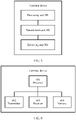
- FIG. 5 is a possible schematic structural diagram of a terminal device used in the foregoing implementation.
- the terminal device may be one of the terminal devices 20A to 20C shown in FIG. 1 .
- the terminal device includes a processing unit 501, a transmission unit 502, and a receiving unit 503.
- the processing unit 501 is configured to determine first configuration information, where the first configuration information is used to determine at least one first sidelink logical channel, and the first sidelink logical channel is used to transmit direct communication data.
- the processing unit 501 determines that type-1 data and type-2 data need to be transmitted at a same time, the processing unit 501 is further configured to allocate a first transmit power for first data based on the first configuration information, where the type-1 data and the type-2 data are data to be transmitted by using different transmission resources, and the first data is the type-1 data to be transmitted by using the first sidelink logical channel.
- the processing unit 501 determines the first configuration information based on an RRC message or a broadcast message received by the receiving unit 503.
- the processing unit 501 may alternatively determine the first configuration information based on a preconfiguration. Content and a form of the first configuration information may be the same as those described in step S201 in the implementation shown in FIG. 2 . Details are not described again herein.
- the processing unit 501 may further determine, based on second information received by the receiving unit 503, to start a preferential power allocation operation.
- the processing unit 501 may further determine, by using the method described in step S202 in the implementation shown in FIG. 2 , that the type-1 data and the type-2 data are to be transmitted at the same time.
- the processing unit 501 determines that a transmission resource used for the type-1 data and a transmission resource used for the type-2 data partly or completely overlap each other in time domain; or the processing unit 501 determines that a subframe for transmitting the type-1 data and a subframe for transmitting the type-2 data partly or completely overlap each other in time domain.
- the processing unit 501 may determine the first sidelink logical channel based on a first identifier, as described in step S202 in the implementation shown in FIG. 2 .
- the first identifier is a priority identifier or a logical channel identifier.
- the processing unit 501 may also determine a second sidelink logical channel based on a second identifier, and further determine the first sidelink logical channel.
- the processing unit 501 may alternatively determine the first sidelink logical channel based on the first identifier and the second identifier. The foregoing corresponding content is not described again herein.
- the processing unit 501 is further configured to determine the first sidelink logical channel based on a third identifier, as described in step S202 in the implementation shown in FIG. 2 .
- the processing unit 501 may alternatively determine the first sidelink logical channel based on first indication information. For example, the processing unit 501 determines all sidelink logical channels as the first sidelink logical channels based on the first indication information.
- the processing unit 501 is further configured to preferentially allocate a first transmit power for the first data, as described in step S202 in the implementation shown in FIG. 2 .
- the processing unit 501 is further configured to encapsulate the first data in a first PDU.
- the processing unit 501 is further configured to control the transmission unit 502 to transmit the first protocol data unit by using the first transmit power.
- the processing unit 501 is further configured to allocate the first transmit power for the first data based on a first limited power, where the first transmit power is higher than the first limited power and lower than or equal to a maximum transmit power currently allowed by the terminal device.
- the processing unit 501 allocates the first transmit power for the first data based on a first limited power, where the first transmit power is lower than or equal to the first limited power.
- the processing unit 501 is further configured to add the first limited power to the first configuration information or a second message, or preconfigure the first limited power.
- the terminal device may preferentially allocate a transmit power for data on the first sidelink logical channel, to ensure transmission quality of the data and improve transmission performance of the system.
- the processing unit 501 is further configured to encapsulate non-V2X service data in a second PDU, and determine a transmit power used for transmitting the second PDU.
- the processing unit 501 is further configured to: if determining that V2X service data and non-V2X service data are not to be transmitted at a same time, determine the second transmit power for the V2X service data based on the currently allowed maximum transmit power, as described in step S202 in the implementation shown in FIG. 2 ; or the processing unit 501 determines the second transmit power based on a current link loss between the terminal device and a network device.
- the processing unit 501 is further configured to control the transmission unit 502 to transmit the V2X service data by using the second transmit power.
- the processing unit 501 is further configured to encapsulate second data on the second sidelink logical channel in the second PDU.
- the processing unit 501 is further configured to allocate a third transmit power for the non-V2X service data, and allocate a fourth transmit power for the second data.
- the transmission unit 502 is further configured to transmit the first protocol data unit by using the first transmit power.
- the transmission unit 502 is further configured to transmit the V2X service data by using the second transmit power.
- the receiving unit 503 is further configured to receive the first configuration information transmitted by the network device.
- the receiving unit 503 may obtain the first configuration information by receiving an RRC message or a broadcast message transmitted by the network device.
- the receiving unit 503 is further configured to receive the third identifier transmitted by the network device.
- the third identifier may be included in the first configuration information, or may be independent of the first configuration information.
- the receiving unit 503 is further configured to receive the first limited power and a mapping relationship between the first limited power and the first identifier that are transmitted by the network device.
- the receiving unit 503 is further configured to receive the maximum transmit power that is currently allowed to be used and that is transmitted by the network device.
- Functions of the foregoing units in the terminal device may be implemented by hardware or may be implemented by executing corresponding software by hardware.
- each of the foregoing units may be hardware implementing a function of each module, or may be another hardware device that can execute a corresponding computer program to implement each of the foregoing functions.
- FIG. 6 is a possible schematic structural diagram of a terminal device used in the foregoing implementation.
- the terminal device includes a processor 601, a transmitter 602, and a receiver 603.
- the processing unit 501 described in FIG. 5 may be implemented by the processor 601.
- the transmission unit 502 and the receiving unit 503 may be implemented by the transmitter 602 and the receiver 603.
- the transmitter 602 and the receiver 603 may be configured to support the terminal device in receiving or transmitting data from or to the network device in the foregoing implementations.
- the terminal device may further include a memory 604, which may be configured to store program code and data of the terminal device. All components in the terminal device are coupled together to support various functions of the terminal device in the method for data transmission in the implementation described in FIG. 2 .
- FIG. 6 shows only a simplified design of the terminal device.
- the terminal device may include any quantity of transmitters, receivers, processors, memories, and the like.
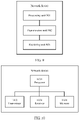
- FIG. 7 is a possible schematic structural diagram of a terminal device used in the foregoing implementation.
- the terminal device may be one of the terminal devices 20A to 20C shown in FIG. 1 .
- the terminal device includes a processing unit 701, a transmission unit 702, and a receiving unit 703.
- the processing unit 701 is configured to determine first configuration information, where the first configuration information is used to determine at least one first sidelink logical channel, and the first sidelink logical channel is used to transmit direct communication data.
- the processing unit 701 is further configured to determine to start a transmission control operation.
- the processing unit 701 is further configured to perform the transmission control operation on first data, where the first data is data that is in to-be-transmitted data and that is to be transmitted by using the first sidelink logical channel, and the transmission control operation includes: controlling, by the processing unit 701, the transmission unit 702 to transmit the first data in a first transmission mode.
- the processing unit 701 determines the first configuration information based on an RRC message or a broadcast message received by the receiving unit 703.
- the processing unit 701 may alternatively determine the first configuration information based on a preconfiguration. Content and a form of the first configuration information may be the same as those described in step S301 in the implementation shown in FIG. 3 . Details are not described again herein.
- the processing unit 701 may be further configured to measure a CBR. When the CBR is greater than a preset threshold, the processing unit 701 determines to start the transmission control operation. The processing unit 701 may alternatively determine, based on first information received by the receiving unit 703, to start the transmission control operation. When determining the first configuration information, the processing unit 701 may further directly determine to start the transmission control operation.
- the processing unit 701 may determine the first sidelink logical channel based on the first identifier, as described in step S303 in the implementation shown in FIG. 3 .
- the first identifier is a priority identifier or a logical channel identifier.
- the processing unit 701 may also determine second sidelink logical channel based on the second identifier, and further determine the first sidelink logical channel.
- the processing unit 701 may alternatively determine the first sidelink logical channel based on the first identifier and the second identifier. The foregoing corresponding content is not described again herein.
- the processing unit 701 may alternatively determine the first sidelink logical channel based on first indication information. For example, the processing unit 701 determines all sidelink logical channels as the first sidelink logical channels based on the first indication information.
- the processing unit 701 is further configured to obtain first transmission mode control information before performing the transmission control operation.
- the processing unit 701 may determine the first transmission mode control information based on an RRC message or a broadcast message received by the receiving unit 703.
- the processing unit 701 may alternatively determine the first transmission mode control information based on a preconfiguration. Content and a form of the first transmission mode control information may be the same as those described in step S303 in the implementation shown in FIG. 3 . Details are not described again herein.
- the processing unit 701 is further configured to determine a first transmission configuration.
- the processing unit 701 may determine the first transmission configuration based on the measured CBR, as described in step S30311 in the implementation shown in FIG. 3 .
- the processing unit 701 may alternatively determine the first transmission configuration based on a probability.
- the processing unit 701 may also determine, based on RRC dedicated signaling or system information received by the receiving unit 703, a plurality of transmission configurations and trigger probabilities corresponding to the plurality of transmission configurations.
- the processing unit 701 is further configured to encapsulate the first data in a first PDU.
- the processing unit 701 is further configured to determine an available transmission resource based on first grant information received by the receiving unit 703.
- the processing unit 701 is further configured to control the transmission unit 702 to transmit the first PDU by using the first transmission configuration.
- the terminal device may suppress data transmission on the first sidelink logical channel to improve transmission performance of a system.
- the processing unit 701 is further configured to determine a drop probability of the first sidelink logical channel, as described in step S30321 in the implementation shown in FIG. 3 .
- the processing unit 701 is further configured to control the transmission unit 702 to drop the first data at a PDCP layer or a MAC layer.
- the terminal device may drop some data of the first sidelink logical channel to improve transmission performance of the system.
- the processing unit 701 is further configured to control the transmission unit 702 to transmit the first data on the first sidelink logical channel in a second transmission mode, as described in step S303 in the implementation shown in FIG. 3 .
- the processing unit 701 is further configured to determine second transmission mode control information.
- a manner of obtaining the second transmission mode control information and content and a form of the second transmission mode control information may be the same as those described in step S303 in the implementation shown in FIG. 3 . Details are not described again herein.
- the processing unit 701 may be further configured to determine the second sidelink logical channel based on the first configuration information.
- the processing unit 701 controls the transmission unit 702 to transmit second data by using a third transmission configuration.
- the transmission unit 702 is further configured to transmit the CBR to a network device.
- the transmission unit 702 is further configured to transmit the first data in the first transmission mode after the transmission control operation is started. Specifically, the transmission unit 702 transmits the first data by using the first transmission configuration.
- the transmission unit 702 may be further configured to transmit the first data in the second transmission mode before the transmission control operation is started. Specifically, the transmission unit 702 transmits the first data by using a second transmission configuration.
- the transmission unit 702 is further configured to drop the first data.
- the transmission unit 702 may be further configured to transmit the second data on the second sidelink logical channel in the second transmission mode. Specifically, the transmission unit 702 transmits the second data by using the third transmission configuration.
- the receiving unit 703 is further configured to receive the first configuration information transmitted by the network device.
- the receiving unit 703 may obtain the first configuration information by receiving an RRC message or a broadcast message transmitted by the network device.
- the receiving unit 703 is further configured to receive the first information transmitted by the network device.
- the first information is used by the processing unit 701 to determine to start the transmission control operation, as described in the implementation shown in FIG. 3 .
- the receiving unit 703 is further configured to receive the first transmission mode control information and/or the second transmission mode control information transmitted by the network device.
- the receiving unit 703 may obtain the first transmission mode control information and/or the second transmission mode control information by receiving an RRC message or a broadcast message transmitted by the network device.
- the receiving unit 703 may be configured to receive a mapping relationship that is between the CBR and the first transmission configuration and that is transmitted by the network device.
- the receiving unit 703 may be further configured to receive the plurality of transmission configurations and the trigger probabilities corresponding to the plurality of transmission configurations that are transmitted by the network device.
- the receiving unit 703 may be further configured to receive the drop probability that is of the first sidelink logical channel and that is transmitted by the network device.
- Functions of the foregoing units in the terminal device may be implemented by hardware or may be implemented by executing corresponding software by hardware.
- each of the foregoing units may be hardware implementing a function of each module, or may be another hardware device that can execute a corresponding computer program to implement each of the foregoing functions.
- FIG. 8 is a possible schematic structural diagram of a terminal device used in the foregoing implementation.
- the terminal device includes a processor 801, a transmitter 802, and a receiver 803.
- the processing unit 701 described in FIG. 7 may be implemented by the processor 801.
- the transmission unit 702 and the receiving unit 703 may be implemented by the transmitter 802 and the receiver 803.
- the transmitter 802 and the receiver 803 may be configured to support the terminal device in receiving or transmitting data from or to the network device in the foregoing implementations.
- the terminal device may further include a memory 804, which may be configured to store program code and data of the terminal device. All components in the terminal device are coupled together to support various functions of the terminal device in the method for data transmission in the implementation described in FIG. 3 .
- FIG. 8 shows only a simplified design of the terminal device.
- the terminal device may include any quantity of transmitters, receivers, processors, memories, and the like.
- FIG. 9 is a possible schematic structural diagram of a network device used in the foregoing implementation.
- the network device may be the network device 10 shown in FIG. 1 .
- the network device includes a processing unit 901, a transmission unit 902, and a receiving unit 903.
- the processing unit 901 is configured to determine first configuration information.
- the first configuration information is used to determine at least one first sidelink logical channel.
- the first sidelink logical channel supports a transmission control operation.
- Content and a form of the first configuration information may be the same as those described in step S401 in the implementation shown in FIG. 4 . Details are not described again herein.
- the transmission unit 902 is configured to transmit the first configuration information to a terminal device by using RRC message or a broadcast message.
- the transmission unit 902 is further configured to transmit a fourth identifier to the terminal device.
- the fourth identifier may be included in the first configuration information, or may be independent of the first configuration information.
- the transmission unit 902 is further configured to transmit first information or second information to the terminal device, where the first information or the second information is used to instruct the terminal device to start the transmission control operation.
- the transmission unit 902 may be configured to transmit first transmission mode control information to the terminal device, where the first transmission mode control information is used to instruct the terminal device to transmit first data on the first sidelink logical channel in a first transmission mode, and the first transmission mode includes using a first transmission configuration and/or dropping data packets.
- the transmission unit 902 may be further configured to transmit second transmission mode control information to the terminal device.
- the transmission unit 902 may transmit the first transmission mode control information and/or the second transmission mode control information by using an RRC message or a broadcast message. Content and forms of the first transmission mode control information and/or the second transmission mode control information may be the same as those described in step S403 in the implementation shown in FIG. 4 . Details are not described again herein.
- the transmission unit 902 is further configured to transmit a first limited power, a mapping relationship between the first limited power and a first identifier, a maximum transmit power, a fifth transmit power, and a sixth transmit power to the terminal device, as described in the implementation shown in FIG. 3 .
- the receiving unit 903 is configured to receive a CBR transmitted by the terminal device.
- the CBR is used to indicate a load degree of a transmission channel.
- the network device can configure a logical channel supporting the transmission control operation for the terminal device, and therefore transmission performance of a system in a high-density service scenario is ensured.
- Functions of the foregoing units in the network device may be implemented by hardware or may be implemented by executing corresponding software by hardware.
- each of the foregoing units may be hardware implementing a function of each module, or may be another hardware device that can execute a corresponding computer program to implement each of the foregoing functions.
- FIG. 10 is a possible schematic structural diagram of a network device used in a non claimed implementation.
- the network device includes a processor 1001, a transmitter 1002, and a receiver 1003.
- the processing unit 901 described in FIG. 9 may be implemented by the processor 1001.
- the transmission unit 902 and the receiving unit 903 may be implemented by the transmitter 1002 and the receiver 1003.
- the transmitter 1002 and the receiver 1003 may be configured to support the network device in receiving or transmitting data from or to the terminal device in the foregoing implementations.
- the network device may further include a memory 1004, which may be configured to store program code and data of the network device. All components in the network device are coupled together to support various functions of the network device in the method for data transmission in the implementation described in FIG. 4 .
- FIG. 10 shows only a simplified design of the terminal device.
- the network device may include any quantity of transmitters, receivers, processors, memories, and the like.
- the processor in this implementation of the present disclosure may be a central processing unit (CPU), a general purpose processor, a digital signal processor (DSP), an application-specific integrated circuit (ASIC), a field programmable gate array (FPGA) or another programmable logic device, a transistor logic device, a hardware component, or any combination thereof.
- the processor may implement or execute various example logical blocks, modules, and circuits described with reference to content disclosed in the present disclosure.
- the processor may be a combination of processors implementing a computing function, for example, a combination of one or more microprocessors, or a combination of the DSP and a microprocessor.
- Steps of the methods or algorithms described in the implementations of the present disclosure may be directly embedded into hardware, a software module executed by a processing unit, or a combination thereof.
- the software module may be stored in a RAM memory, a flash memory, a ROM memory, an EPROM memory, an EEPROM memory, a register, a hard disk, a removable magnetic disk, a CD-ROM, or a storage medium of any other form in the art.
- the storage medium may be connected to the processing unit, so that the processing unit can decode information from the storage medium and can write information to the storage medium.
- the storage medium may alternatively be integrated in the processing unit.
- the processing unit and the storage medium may be configured in the ASIC, and the ASIC may be configured in a terminal device.
- the processing unit and the storage medium may also be configured in different components of the terminal device.
- the functions described in the implementations of the present disclosure may be implemented by hardware, software, firmware, or any combination thereof. If the functions are implemented by software, the functions may be stored on a computer-readable medium, or transmitted in a form of one or more instructions or code on a computer-readable medium.
- the computer-readable medium includes a computer storage medium and a communications medium that allows a computer program to be transferred from one place to another place.
- the storage medium may be an available medium that may be accessed by any general or special computer.
- the computer-readable medium may include but is not limited to a RAM, a ROM, an EEPROM, a CD-ROM or another optical disc storage, a disk storage or another magnetic storage device, or any other medium that can be used to carry or store program code in a form of an instruction or a data structure and another form that can be decoded by a general or special computer or a general or special processing unit.
- any connection may be appropriately defined as a computer-readable medium.
- the transmission medium may also be included in the defined computer-readable medium.
- the disc (disc) and the disk (disk) include a compressed disk, a laser disc, an optical disc, a DVD, a floppy disk, and a Blu-ray disc.
- the disk generally copies data by a magnetic means, and the disc generally copies data optically by a laser means.
- the foregoing combination may also be included in the computer-readable medium.
Landscapes
- Engineering & Computer Science (AREA)
- Computer Networks & Wireless Communication (AREA)
- Signal Processing (AREA)
- Mobile Radio Communication Systems (AREA)
Claims (7)
- Procédé de transmission de données dans un réseau sans fil, comprenant :la détermination (201), par un dispositif terminal, de premières informations de configuration, les premières informations de configuration étant utilisées pour déterminer au moins un premier canal logique de liaison latérale, et le premier canal logique de liaison latérale étant utilisé pour transmettre des données de communication directe ;la détermination, par le dispositif terminal, établissant si des données de type 1 et des données de type 2 doivent être transmises en même temps (202),lorsque le dispositif terminal détermine que les données de type 1 et les données de type 2 doivent être transmises en même temps (202), l'attribution, par le dispositif terminal, d'une première puissance de transmission pour les premières données sur la base des premières informations de configuration, les données de type 1 et les données de type 2 étant des données de service de différents types devant être transmises en utilisant différentes ressources de transmission, et les premières données étant les données de type 1 devant être transmises en utilisant le premier canal logique de liaison latérale,dans lequel les premières informations de configuration comprennent au moins un premier identifiant, le premier identifiant est un identifiant de priorité ou un identifiant de canal logique, et le premier identifiant est utilisé pour déterminer le premier canal logique de liaison latérale ; etdans lequel le fait que le premier identifiant est utilisé pour déterminer le premier canal logique de liaison latérale comprend :le dispositif terminal détermine un canal logique de liaison latérale ayant le premier identifiant comme premier canal logique de liaison latérale ; oulorsqu'au moins un parmi des canaux logiques de liaison latérale associés à des données encapsulées dans une unité de données de protocole du dispositif terminal a le premier identifiant, le dispositif terminal détermine tous les canaux logiques de liaison latérale associés aux données encapsulées dans l'unité de données de protocole comme étant les premiers canaux logiques de liaison latérale,dans lequel l'attribution, par le dispositif terminal, d'une première puissance de transmission pour des premières données sur la base des premières informations de configuration comprend :l'attribution, par le dispositif terminal, de la première puissance de transmission pour les premières données sur la base d'une première puissance limitée, la première puissance de transmission étant supérieure à la première puissance limitée et inférieure ou égale à une puissance de transmission maximale actuellement autorisée par le dispositif terminal, oula première puissance de transmission étant inférieure ou égale à la première puissance limitée,caractérisé par le fait que la première puissance limitée a une relation de mappage avec le premier identifiant et est utilisée pour indiquer une puissance de transmission maximale disponible pour des données sur un canal logique de liaison latérale indiqué par le premier identifiant.
- Procédé selon la revendication 1, dans lequel la détermination, par le dispositif terminal, établissant si des données de type 1 et des données de type 2 doivent être transmises en même temps comprend :la détermination, par le dispositif terminal, établissant si une ressource de transmission utilisée pour les données de type 1 et une ressource de transmission utilisée pour les données de type 2 se chevauchent partiellement ou complètement dans le domaine temporel ; oula détermination, par le dispositif terminal, établissant si une sous-trame pour transmettre les données de type 1 et une sous-trame pour transmettre les données de type 2 se chevauchent partiellement ou complètement dans le domaine temporel.
- Procédé selon la revendication 1 ou 2, dans lequel les premières informations de configuration comprennent des premières informations d'indication, et les premières informations d'indication sont utilisées pour indiquer que certains ou tous les canaux logiques de liaison latérale sont les premiers canaux logiques de liaison latérale.
- Procédé selon la revendication 1, dans lequel la première puissance limitée est portée dans les premières informations de configuration ou portée dans un second message, ou la première puissance limitée est préconfigurée par le dispositif terminal.
- Procédé selon l'une quelconque des revendications 1 à 4, le procédé comprenant en outre :la détermination, par le dispositif terminal, d'au moins un second canal logique de liaison latérale sur la base des premières informations de configuration, le second canal logique de liaison latérale étant utilisé pour transmettre des données de communication directe ;si le dispositif terminal détermine que les données de type 1 et les données de type 2 doivent être transmises en même temps, l'attribution, par le dispositif terminal, d'une troisième puissance de transmission pour les données de type 2 ;l'attribution, par le dispositif terminal, d'une quatrième puissance de transmission pour les secondes données sur la base de la puissance de transmission maximale autorisée et de la troisième puissance de transmission, les secondes données étant les données de type 1 devant être transmises en utilisant le second canal logique de liaison latérale ; etla transmission, par le dispositif terminal, des secondes données en utilisant la quatrième puissance de transmission.
- Dispositif terminal, comprenant :une unité de traitement (501), configurée pour déterminer des premières informations de configuration, dans laquelle les premières informations de configuration sont utilisées pour déterminer au moins un premier canal logique de liaison latérale, et le premier canal logique de liaison latérale est utilisé pour transmettre des données de communication directe ;dans lequell'unité de traitement est configurée pour déterminer si des données de type 1 et des données de type 2 doivent être transmises en même temps, et lorsque l'unité de traitement détermine que des données de type 1 et des données de type 2 doivent être transmises en même temps,l'unité de traitement est en outre configurée pour attribuer une première puissance de transmission pour des premières données sur la base des premières informations de configuration, les données de type 1 et les données de type 2 étant des données de service de différents types qui doivent être transmises en utilisant différentes ressources de transmission, et les premières données étant les données de type 1 devant être transmises en utilisant le premier canal logique de liaison latérale,dans lequel les premières informations de configuration comprennent au moins un premier identifiant, le premier identifiant est un identifiant de priorité ou un identifiant de canal logique, et le premier identifiant est utilisé pour déterminer le premier canal logique de liaison latérale ; etdans lequel le fait que le premier identifiant est utilisé pour déterminer le premier canal logique de liaison latérale comprend :l'unité de traitement détermine un canal logique de liaison latérale ayant le premier identifiant comme premier canal logique de liaison latérale ; oulorsqu'au moins un des canaux logiques de liaison latérale associés à des données encapsulées dans une unité de données de protocole du dispositif terminal a le premier identifiant, l'unité de traitement détermine tous les canaux logiques de liaison latérale associés aux données encapsulées dans l'unité de données de protocole comme étant les premiers canaux logiques de liaison latérale,dans lequel le fait que l'unité de traitement est en outre configurée pour attribuer une première puissance de transmission pour les premières données sur la base des premières informations de configuration comprend :l'unité de traitement est configurée pour attribuer la première puissance de transmission pour les premières données sur la base d'une première puissance limitée, dans laquelle la première puissance de transmission est supérieure à la première puissance limitée et inférieure ou égale à une puissance de transmission maximale actuellement autorisée par le dispositif terminal ou la première puissance de transmission est inférieure ou égale à la première puissance limitée,caractérisé par le fait que la première puissance limitée a une relation de mappage avec le premier identifiant et est utilisée pour indiquer une puissance de transmission maximale disponible pour des données sur un canal logique de liaison latérale indiqué par le premier identifiant.
- Dispositif terminal selon la revendication 6, dans lequel le fait que l'unité de traitement est configurée pour déterminer que des données de type 1 et des données de type 2 doivent être transmises en même temps comprend :l'unité de traitement détermine si une ressource de transmission utilisée pour les données de type 1 et une ressource de transmission utilisée pour les données de type 2 se chevauchent partiellement ou complètement dans le domaine temporel ; oul'unité de traitement détermine si une sous-trame pour transmettre les données de type 1 et une sous-trame pour transmettre les données de type 2 se chevauchent partiellement ou complètement dans le domaine temporel.
Applications Claiming Priority (1)
| Application Number | Priority Date | Filing Date | Title |
|---|---|---|---|
| PCT/CN2016/104757 WO2018082055A1 (fr) | 2016-11-04 | 2016-11-04 | Procédé, appareil et système de transmission de données de réseau sans fil |
Publications (3)
| Publication Number | Publication Date |
|---|---|
| EP3528566A1 EP3528566A1 (fr) | 2019-08-21 |
| EP3528566A4 EP3528566A4 (fr) | 2019-09-25 |
| EP3528566B1 true EP3528566B1 (fr) | 2022-05-25 |
Family
ID=62076344
Family Applications (1)
| Application Number | Title | Priority Date | Filing Date |
|---|---|---|---|
| EP16920797.4A Active EP3528566B1 (fr) | 2016-11-04 | 2016-11-04 | Procédé, appareil et système de transmission de données de réseau sans fil |
Country Status (4)
| Country | Link |
|---|---|
| US (1) | US10798708B2 (fr) |
| EP (1) | EP3528566B1 (fr) |
| CN (1) | CN109891970B (fr) |
| WO (1) | WO2018082055A1 (fr) |
Families Citing this family (4)
| Publication number | Priority date | Publication date | Assignee | Title |
|---|---|---|---|---|
| US11564118B2 (en) * | 2018-08-30 | 2023-01-24 | Lg Electronics Inc. | Method and apparatus for restricting measurement based on result of a reference measurement in wireless communication system |
| WO2020093335A1 (fr) * | 2018-11-08 | 2020-05-14 | Oppo广东移动通信有限公司 | Procédé et dispositif terminal de transmission de données de liaison latérale |
| US11582719B2 (en) * | 2019-10-03 | 2023-02-14 | Mediatek Inc. | Enhancement of logical channel prioritization for sidelink transmission |
| WO2023220895A1 (fr) * | 2022-05-16 | 2023-11-23 | Oppo广东移动通信有限公司 | Procédé de communication sans fil, dispositif terminal et dispositif de réseau |
Family Cites Families (14)
| Publication number | Priority date | Publication date | Assignee | Title |
|---|---|---|---|---|
| EP3451750B1 (fr) * | 2012-05-31 | 2021-04-21 | Interdigital Patent Holdings, Inc. | Commande de puissance de liaison transversale de dispositif à dispositif (d2d) |
| EP2995156B1 (fr) * | 2013-05-08 | 2020-12-02 | Guangdong Oppo Mobile Telecommunications Corp., Ltd. | Gestion améliorée de l'émission de communications de réseau et de la réception simultanée de communications d2d ou de la réception de communications de réseau et de l'émission simultanée de communications d2d |
| JP2015035712A (ja) * | 2013-08-08 | 2015-02-19 | Kddi株式会社 | 無線基地局装置、無線端末装置、無線通信システム、端末間直接通信制御方法およびコンピュータプログラム |
| CN104469961A (zh) * | 2013-09-25 | 2015-03-25 | 中兴通讯股份有限公司 | 一种设备到设备的通信方法、设备和系统 |
| KR101506598B1 (ko) | 2013-11-29 | 2015-03-27 | 현대모비스 주식회사 | 차량간 통신을 위한 통신 장치 |
| CN104811892B (zh) | 2014-01-29 | 2020-03-13 | 中兴通讯股份有限公司 | 一种资源分配方法、装置及系统 |
| CN104936297B (zh) * | 2014-03-18 | 2020-01-10 | 北京三星通信技术研究有限公司 | 配置有包含d2d子帧服务小区的系统的功率控制方法及用户设备 |
| WO2016182410A1 (fr) * | 2015-05-14 | 2016-11-17 | 엘지전자 (주) | Procédé d'émission et de réception de signal d2d dans un système de communication sans fil, et appareil associé |
| WO2016186268A1 (fr) * | 2015-05-15 | 2016-11-24 | 엘지전자(주) | Procédé de transfert de données dans un système de communication sans fil prenant en charge une communication de dispositif à dispositif, et appareil associé |
| US20190075546A1 (en) * | 2015-11-05 | 2019-03-07 | Ntt Docomo, Inc. | User apparatus, base station, signal transmission method, and resource allocation method |
| US10743267B2 (en) * | 2015-11-05 | 2020-08-11 | Telefonaktiebolaget Lm Ericsson (Publ) | Dropping measurements of synchronization signals |
| CN110140408B (zh) * | 2016-11-02 | 2022-08-26 | Lg电子株式会社 | 用于在无线通信系统中执行副链路发送的方法及其装置 |
| KR102275288B1 (ko) * | 2017-01-03 | 2021-07-09 | 삼성전자 주식회사 | V2X 통신을 위한 inter-carrier 방법 |
| US11224007B2 (en) * | 2018-11-19 | 2022-01-11 | Huawei Technologies Co., Ltd. | System and method for supporting sidelink radio bearers |
-
2016
- 2016-11-04 EP EP16920797.4A patent/EP3528566B1/fr active Active
- 2016-11-04 WO PCT/CN2016/104757 patent/WO2018082055A1/fr unknown
- 2016-11-04 CN CN201680090498.2A patent/CN109891970B/zh active Active
-
2019
- 2019-05-02 US US16/401,751 patent/US10798708B2/en active Active
Non-Patent Citations (1)
| Title |
|---|
| CATT: "CR for introducing inter-band E-UTRA_V2X operation", vol. RAN WG4, no. Ljubljana, Slovenia; 20161010 - 20161014, 9 October 2016 (2016-10-09), XP051152613, Retrieved from the Internet <URL:http://www.3gpp.org/ftp/Meetings_3GPP_SYNC/RAN4/Docs/> [retrieved on 20161009] * |
Also Published As
| Publication number | Publication date |
|---|---|
| CN109891970B (zh) | 2021-07-16 |
| EP3528566A1 (fr) | 2019-08-21 |
| EP3528566A4 (fr) | 2019-09-25 |
| CN109891970A (zh) | 2019-06-14 |
| WO2018082055A1 (fr) | 2018-05-11 |
| US10798708B2 (en) | 2020-10-06 |
| US20190261376A1 (en) | 2019-08-22 |
Similar Documents
| Publication | Publication Date | Title |
|---|---|---|
| EP3709733B1 (fr) | Procédé de configuration de ressources en communication dispositif à dispositif (d2d), dispositif de terminal et dispositif de réseau | |
| US10660118B2 (en) | Logical channel priority reconfiguration for MAC-CES in NR | |
| US10075940B2 (en) | Method for transmitting buffer status report in device-to-device communication, and device thereof | |
| US20200068624A1 (en) | Data sending method and apparatus thereof | |
| US11064557B2 (en) | Method and device for establishing radio resource control connection | |
| US10798708B2 (en) | Method for data transmission in wireless network, apparatus, and system | |
| EP3370364B1 (fr) | Procédé et appareil de transmission de services | |
| EP3793296B1 (fr) | Procédé et dispositif de communication | |
| WO2017163185A1 (fr) | Sélection de classe de priorité d'accès au canal | |
| EP3461178B1 (fr) | Programmation dans un transfer intercellulaire | |
| EP3255928B1 (fr) | Procédé d'accès aléatoire et équipement utilisateur | |
| EP3209050B1 (fr) | Procédé de transmission de canal de commande de liaison descendante physique, dispositif station de base, et équipement utilisateur | |
| WO2013166670A1 (fr) | Procédé et dispositif pour configurer les ressources d'un canal montant | |
| US20200396728A1 (en) | Communication Method And Communications Apparatus | |
| WO2022067788A1 (fr) | Procédé et appareil de transmission de données, dispositif et support de stockage | |
| JP7478164B2 (ja) | アップリンク伝送方法、アップリンクスケジューリング方法、装置及び通信システム | |
| EP3955692A1 (fr) | Procédé et dispositif de traitement d'informations, et support d'enregistrement | |
| WO2020124534A1 (fr) | Procédé et dispositif de transmission de données | |
| JPWO2019214301A5 (fr) | ||
| WO2020051767A1 (fr) | Procédé de transmission d'informations et de réception d'informations et dispositif de communication | |
| WO2023013610A1 (fr) | Dispositif de communication, dispositif de station de base et procédé de communication | |
| WO2023013548A1 (fr) | Appareil de communication et procédé de commande de communication | |
| WO2023013547A1 (fr) | Dispositif de communication, station de base et procédé de communication | |
| US20220394771A1 (en) | Spectrum extension for initial access |
Legal Events
| Date | Code | Title | Description |
|---|---|---|---|
| STAA | Information on the status of an ep patent application or granted ep patent |
Free format text: STATUS: THE INTERNATIONAL PUBLICATION HAS BEEN MADE |
|
| PUAI | Public reference made under article 153(3) epc to a published international application that has entered the european phase |
Free format text: ORIGINAL CODE: 0009012 |
|
| STAA | Information on the status of an ep patent application or granted ep patent |
Free format text: STATUS: REQUEST FOR EXAMINATION WAS MADE |
|
| 17P | Request for examination filed |
Effective date: 20190517 |
|
| AK | Designated contracting states |
Kind code of ref document: A1 Designated state(s): AL AT BE BG CH CY CZ DE DK EE ES FI FR GB GR HR HU IE IS IT LI LT LU LV MC MK MT NL NO PL PT RO RS SE SI SK SM TR |
|
| AX | Request for extension of the european patent |
Extension state: BA ME |
|
| A4 | Supplementary search report drawn up and despatched |
Effective date: 20190822 |
|
| RIC1 | Information provided on ipc code assigned before grant |
Ipc: H04W 76/14 20180101AFI20190816BHEP Ipc: H04W 52/28 20090101ALN20190816BHEP Ipc: H04W 52/38 20090101ALI20190816BHEP |
|
| DAV | Request for validation of the european patent (deleted) | ||
| DAX | Request for extension of the european patent (deleted) | ||
| STAA | Information on the status of an ep patent application or granted ep patent |
Free format text: STATUS: EXAMINATION IS IN PROGRESS |
|
| 17Q | First examination report despatched |
Effective date: 20210210 |
|
| STAA | Information on the status of an ep patent application or granted ep patent |
Free format text: STATUS: EXAMINATION IS IN PROGRESS |
|
| REG | Reference to a national code |
Ref country code: DE Ref legal event code: R079 Ref document number: 602016072451 Country of ref document: DE Free format text: PREVIOUS MAIN CLASS: H04W0072040000 Ipc: H04W0076140000 |
|
| GRAP | Despatch of communication of intention to grant a patent |
Free format text: ORIGINAL CODE: EPIDOSNIGR1 |
|
| STAA | Information on the status of an ep patent application or granted ep patent |
Free format text: STATUS: GRANT OF PATENT IS INTENDED |
|
| RIC1 | Information provided on ipc code assigned before grant |
Ipc: H04W 52/28 20090101ALN20211213BHEP Ipc: H04W 52/36 20090101ALI20211213BHEP Ipc: H04W 52/38 20090101ALI20211213BHEP Ipc: H04W 76/14 20180101AFI20211213BHEP |
|
| INTG | Intention to grant announced |
Effective date: 20220110 |
|
| GRAS | Grant fee paid |
Free format text: ORIGINAL CODE: EPIDOSNIGR3 |
|
| GRAA | (expected) grant |
Free format text: ORIGINAL CODE: 0009210 |
|
| STAA | Information on the status of an ep patent application or granted ep patent |
Free format text: STATUS: THE PATENT HAS BEEN GRANTED |
|
| AK | Designated contracting states |
Kind code of ref document: B1 Designated state(s): AL AT BE BG CH CY CZ DE DK EE ES FI FR GB GR HR HU IE IS IT LI LT LU LV MC MK MT NL NO PL PT RO RS SE SI SK SM TR |
|
| REG | Reference to a national code |
Ref country code: GB Ref legal event code: FG4D |
|
| REG | Reference to a national code |
Ref country code: CH Ref legal event code: EP |
|
| REG | Reference to a national code |
Ref country code: AT Ref legal event code: REF Ref document number: 1494767 Country of ref document: AT Kind code of ref document: T Effective date: 20220615 Ref country code: DE Ref legal event code: R096 Ref document number: 602016072451 Country of ref document: DE |
|
| REG | Reference to a national code |
Ref country code: IE Ref legal event code: FG4D |
|
| REG | Reference to a national code |
Ref country code: LT Ref legal event code: MG9D |
|
| REG | Reference to a national code |
Ref country code: NL Ref legal event code: MP Effective date: 20220525 |
|
| REG | Reference to a national code |
Ref country code: AT Ref legal event code: MK05 Ref document number: 1494767 Country of ref document: AT Kind code of ref document: T Effective date: 20220525 |
|
| PG25 | Lapsed in a contracting state [announced via postgrant information from national office to epo] |
Ref country code: SE Free format text: LAPSE BECAUSE OF FAILURE TO SUBMIT A TRANSLATION OF THE DESCRIPTION OR TO PAY THE FEE WITHIN THE PRESCRIBED TIME-LIMIT Effective date: 20220525 Ref country code: PT Free format text: LAPSE BECAUSE OF FAILURE TO SUBMIT A TRANSLATION OF THE DESCRIPTION OR TO PAY THE FEE WITHIN THE PRESCRIBED TIME-LIMIT Effective date: 20220926 Ref country code: NO Free format text: LAPSE BECAUSE OF FAILURE TO SUBMIT A TRANSLATION OF THE DESCRIPTION OR TO PAY THE FEE WITHIN THE PRESCRIBED TIME-LIMIT Effective date: 20220825 Ref country code: NL Free format text: LAPSE BECAUSE OF FAILURE TO SUBMIT A TRANSLATION OF THE DESCRIPTION OR TO PAY THE FEE WITHIN THE PRESCRIBED TIME-LIMIT Effective date: 20220525 Ref country code: LT Free format text: LAPSE BECAUSE OF FAILURE TO SUBMIT A TRANSLATION OF THE DESCRIPTION OR TO PAY THE FEE WITHIN THE PRESCRIBED TIME-LIMIT Effective date: 20220525 Ref country code: HR Free format text: LAPSE BECAUSE OF FAILURE TO SUBMIT A TRANSLATION OF THE DESCRIPTION OR TO PAY THE FEE WITHIN THE PRESCRIBED TIME-LIMIT Effective date: 20220525 Ref country code: GR Free format text: LAPSE BECAUSE OF FAILURE TO SUBMIT A TRANSLATION OF THE DESCRIPTION OR TO PAY THE FEE WITHIN THE PRESCRIBED TIME-LIMIT Effective date: 20220826 Ref country code: FI Free format text: LAPSE BECAUSE OF FAILURE TO SUBMIT A TRANSLATION OF THE DESCRIPTION OR TO PAY THE FEE WITHIN THE PRESCRIBED TIME-LIMIT Effective date: 20220525 Ref country code: ES Free format text: LAPSE BECAUSE OF FAILURE TO SUBMIT A TRANSLATION OF THE DESCRIPTION OR TO PAY THE FEE WITHIN THE PRESCRIBED TIME-LIMIT Effective date: 20220525 Ref country code: BG Free format text: LAPSE BECAUSE OF FAILURE TO SUBMIT A TRANSLATION OF THE DESCRIPTION OR TO PAY THE FEE WITHIN THE PRESCRIBED TIME-LIMIT Effective date: 20220825 Ref country code: AT Free format text: LAPSE BECAUSE OF FAILURE TO SUBMIT A TRANSLATION OF THE DESCRIPTION OR TO PAY THE FEE WITHIN THE PRESCRIBED TIME-LIMIT Effective date: 20220525 |
|
| PG25 | Lapsed in a contracting state [announced via postgrant information from national office to epo] |
Ref country code: RS Free format text: LAPSE BECAUSE OF FAILURE TO SUBMIT A TRANSLATION OF THE DESCRIPTION OR TO PAY THE FEE WITHIN THE PRESCRIBED TIME-LIMIT Effective date: 20220525 Ref country code: PL Free format text: LAPSE BECAUSE OF FAILURE TO SUBMIT A TRANSLATION OF THE DESCRIPTION OR TO PAY THE FEE WITHIN THE PRESCRIBED TIME-LIMIT Effective date: 20220525 Ref country code: LV Free format text: LAPSE BECAUSE OF FAILURE TO SUBMIT A TRANSLATION OF THE DESCRIPTION OR TO PAY THE FEE WITHIN THE PRESCRIBED TIME-LIMIT Effective date: 20220525 Ref country code: IS Free format text: LAPSE BECAUSE OF FAILURE TO SUBMIT A TRANSLATION OF THE DESCRIPTION OR TO PAY THE FEE WITHIN THE PRESCRIBED TIME-LIMIT Effective date: 20220925 |
|
| PG25 | Lapsed in a contracting state [announced via postgrant information from national office to epo] |
Ref country code: SM Free format text: LAPSE BECAUSE OF FAILURE TO SUBMIT A TRANSLATION OF THE DESCRIPTION OR TO PAY THE FEE WITHIN THE PRESCRIBED TIME-LIMIT Effective date: 20220525 Ref country code: SK Free format text: LAPSE BECAUSE OF FAILURE TO SUBMIT A TRANSLATION OF THE DESCRIPTION OR TO PAY THE FEE WITHIN THE PRESCRIBED TIME-LIMIT Effective date: 20220525 Ref country code: RO Free format text: LAPSE BECAUSE OF FAILURE TO SUBMIT A TRANSLATION OF THE DESCRIPTION OR TO PAY THE FEE WITHIN THE PRESCRIBED TIME-LIMIT Effective date: 20220525 Ref country code: EE Free format text: LAPSE BECAUSE OF FAILURE TO SUBMIT A TRANSLATION OF THE DESCRIPTION OR TO PAY THE FEE WITHIN THE PRESCRIBED TIME-LIMIT Effective date: 20220525 Ref country code: DK Free format text: LAPSE BECAUSE OF FAILURE TO SUBMIT A TRANSLATION OF THE DESCRIPTION OR TO PAY THE FEE WITHIN THE PRESCRIBED TIME-LIMIT Effective date: 20220525 Ref country code: CZ Free format text: LAPSE BECAUSE OF FAILURE TO SUBMIT A TRANSLATION OF THE DESCRIPTION OR TO PAY THE FEE WITHIN THE PRESCRIBED TIME-LIMIT Effective date: 20220525 |
|
| REG | Reference to a national code |
Ref country code: DE Ref legal event code: R097 Ref document number: 602016072451 Country of ref document: DE |
|
| PG25 | Lapsed in a contracting state [announced via postgrant information from national office to epo] |
Ref country code: AL Free format text: LAPSE BECAUSE OF FAILURE TO SUBMIT A TRANSLATION OF THE DESCRIPTION OR TO PAY THE FEE WITHIN THE PRESCRIBED TIME-LIMIT Effective date: 20220525 |
|
| PLBE | No opposition filed within time limit |
Free format text: ORIGINAL CODE: 0009261 |
|
| STAA | Information on the status of an ep patent application or granted ep patent |
Free format text: STATUS: NO OPPOSITION FILED WITHIN TIME LIMIT |
|
| 26N | No opposition filed |
Effective date: 20230228 |
|
| PG25 | Lapsed in a contracting state [announced via postgrant information from national office to epo] |
Ref country code: SI Free format text: LAPSE BECAUSE OF FAILURE TO SUBMIT A TRANSLATION OF THE DESCRIPTION OR TO PAY THE FEE WITHIN THE PRESCRIBED TIME-LIMIT Effective date: 20220525 |
|
| PG25 | Lapsed in a contracting state [announced via postgrant information from national office to epo] |
Ref country code: MC Free format text: LAPSE BECAUSE OF FAILURE TO SUBMIT A TRANSLATION OF THE DESCRIPTION OR TO PAY THE FEE WITHIN THE PRESCRIBED TIME-LIMIT Effective date: 20220525 |
|
| REG | Reference to a national code |
Ref country code: CH Ref legal event code: PL |
|
| GBPC | Gb: european patent ceased through non-payment of renewal fee |
Effective date: 20221104 |
|
| REG | Reference to a national code |
Ref country code: BE Ref legal event code: MM Effective date: 20221130 |
|
| PG25 | Lapsed in a contracting state [announced via postgrant information from national office to epo] |
Ref country code: LI Free format text: LAPSE BECAUSE OF NON-PAYMENT OF DUE FEES Effective date: 20221130 Ref country code: CH Free format text: LAPSE BECAUSE OF NON-PAYMENT OF DUE FEES Effective date: 20221130 |
|
| PG25 | Lapsed in a contracting state [announced via postgrant information from national office to epo] |
Ref country code: LU Free format text: LAPSE BECAUSE OF NON-PAYMENT OF DUE FEES Effective date: 20221104 |
|
| PG25 | Lapsed in a contracting state [announced via postgrant information from national office to epo] |
Ref country code: IE Free format text: LAPSE BECAUSE OF NON-PAYMENT OF DUE FEES Effective date: 20221104 Ref country code: GB Free format text: LAPSE BECAUSE OF NON-PAYMENT OF DUE FEES Effective date: 20221104 |
|
| PG25 | Lapsed in a contracting state [announced via postgrant information from national office to epo] |
Ref country code: FR Free format text: LAPSE BECAUSE OF NON-PAYMENT OF DUE FEES Effective date: 20221130 Ref country code: BE Free format text: LAPSE BECAUSE OF NON-PAYMENT OF DUE FEES Effective date: 20221130 |
|
| PG25 | Lapsed in a contracting state [announced via postgrant information from national office to epo] |
Ref country code: IT Free format text: LAPSE BECAUSE OF FAILURE TO SUBMIT A TRANSLATION OF THE DESCRIPTION OR TO PAY THE FEE WITHIN THE PRESCRIBED TIME-LIMIT Effective date: 20220525 |
|
| PGFP | Annual fee paid to national office [announced via postgrant information from national office to epo] |
Ref country code: DE Payment date: 20230929 Year of fee payment: 8 |
|
| PG25 | Lapsed in a contracting state [announced via postgrant information from national office to epo] |
Ref country code: HU Free format text: LAPSE BECAUSE OF FAILURE TO SUBMIT A TRANSLATION OF THE DESCRIPTION OR TO PAY THE FEE WITHIN THE PRESCRIBED TIME-LIMIT; INVALID AB INITIO Effective date: 20161104 |
|
| PG25 | Lapsed in a contracting state [announced via postgrant information from national office to epo] |
Ref country code: CY Free format text: LAPSE BECAUSE OF FAILURE TO SUBMIT A TRANSLATION OF THE DESCRIPTION OR TO PAY THE FEE WITHIN THE PRESCRIBED TIME-LIMIT Effective date: 20220525 |