EP3528528B1 - Verfahren und vorrichtung zur übertragung eines messsignals - Google Patents
Verfahren und vorrichtung zur übertragung eines messsignals Download PDFInfo
- Publication number
- EP3528528B1 EP3528528B1 EP17890622.8A EP17890622A EP3528528B1 EP 3528528 B1 EP3528528 B1 EP 3528528B1 EP 17890622 A EP17890622 A EP 17890622A EP 3528528 B1 EP3528528 B1 EP 3528528B1
- Authority
- EP
- European Patent Office
- Prior art keywords
- terminal device
- network device
- measurement
- signal
- downlink
- Prior art date
- Legal status (The legal status is an assumption and is not a legal conclusion. Google has not performed a legal analysis and makes no representation as to the accuracy of the status listed.)
- Active
Links
Images


Classifications
-
- H—ELECTRICITY
- H04—ELECTRIC COMMUNICATION TECHNIQUE
- H04W—WIRELESS COMMUNICATION NETWORKS
- H04W24/00—Supervisory, monitoring or testing arrangements
- H04W24/08—Testing, supervising or monitoring using real traffic
-
- H—ELECTRICITY
- H04—ELECTRIC COMMUNICATION TECHNIQUE
- H04L—TRANSMISSION OF DIGITAL INFORMATION, e.g. TELEGRAPHIC COMMUNICATION
- H04L5/00—Arrangements affording multiple use of the transmission path
-
- H—ELECTRICITY
- H04—ELECTRIC COMMUNICATION TECHNIQUE
- H04L—TRANSMISSION OF DIGITAL INFORMATION, e.g. TELEGRAPHIC COMMUNICATION
- H04L5/00—Arrangements affording multiple use of the transmission path
- H04L5/003—Arrangements for allocating sub-channels of the transmission path
- H04L5/0053—Allocation of signalling, i.e. of overhead other than pilot signals
-
- H—ELECTRICITY
- H04—ELECTRIC COMMUNICATION TECHNIQUE
- H04W—WIRELESS COMMUNICATION NETWORKS
- H04W24/00—Supervisory, monitoring or testing arrangements
Definitions
- the present invention relates to a method for sending a measurement signal, a method for receiving a measurement signal, a network device, a system, and a computer-readable storage medium.
- Radio resource management in an existing wireless communications system usually uses a downlink measurement signal-based measurement manner.
- a base station sends a downlink measurement signal such as a reference signal RS (Reference Signal), and a terminal device measures a parameter such as RSRP (Reference Signal Received Power, reference signal received power)/RSRQ (Reference Signal Received Quality, reference signal received quality) of the reference signal sent by the base station, and reports a detection result to the base station.
- the base station determines handover and movement of the terminal device based on the detection result.
- a terminal device sends an uplink measurement signal; and a network device, such as a base station or a TRP (transmission reception point, transmission reception point), associated with the terminal device and a neighboring base station or TRP measure the uplink signal sent by the terminal device, and compare detection results of the base stations or the TRPs, so as to determine to hand over the terminal device to a proper cell for service.
- a network device such as a base station or a TRP (transmission reception point, transmission reception point), associated with the terminal device and a neighboring base station or TRP measure the uplink signal sent by the terminal device, and compare detection results of the base stations or the TRPs, so as to determine to hand over the terminal device to a proper cell for service.
- a high-frequency band higher than 6 GHz is introduced for communication, to utilize high-bandwidth and high-rate transmission features of the high-frequency band.
- a narrow beam needs to be used to ensure a propagation distance and a high beam gain. Therefore, a directional narrow beam is also used for transmission of the uplink measurement signal or the downlink measurement signal.
- a relatively large quantity of measurement overheads are generated due to a relatively large quantity of beams in the high-frequency communications.
- WO 2016/003336 A1 describes a method for enabling accurate measurement results for a communication device.
- the method comprises sending, by a serving node serving the communication device and to a neighbour network node, a request for measuring on the uplink reference signals from the communication device; the serving and neighbour nodes receiving, from the communication device, uplink reference signals; the serving and the neighbour nodes obtaining downlink beamforming weights based on the received uplink reference signals; the serving and the neighbour nodes transmitting, to the communication device, specific downlink reference signals adapted for the communication device by using the downlink beamforming weights; the UE transmitting a downlink measurement report to the serving node; the serving node taking a mobility decision based on the UE report.
- WO 2016/209128 A1 discloses a method performed by a network node for managing a geo-fence for use by a source radio network node, wherein the method comprises: receiving indications about signal quality at respective positions of user equipments, wherein the user equipments have been subject to hand-overs from the source radio network node at the respective positions, wherein the hand-overs are based on signal quality measured for the user equipments; defining the geo-fence based on the respective positions and the indications about signal quality, wherein the geo-fence defines a geographical area; and supporting a hand-over of a user equipment from the source radio network node to a target radio network node while using the geo- fence, wherein the hand-over is performed without measurements, by the user equipment, of signal quality towards the target radio network node for the user equipment.
- the present invention provides a a method for sending a measurement signal, a method for receiving a measurement signal, a network device, a system, and a computer-readable storage medium according to the independent claims to reduce system overheads.
- a method for sending a measurement signal comprises: sending, by a network device, downlink measurement signals to a terminal device by using one or more transmit beams; and receiving, by the network device, a detection result, fed back by the terminal device, of signal strength of the downlink measurement signals.
- the method further comprises: when determining, by the network device, that the terminal device enters a cell edge area of the network device by detecting that the detection result is lower than a specified threshold and determining, by the network device, that a quantity of terminal devices that enter the cell edge area is less than a quantity of neighboring base stations, instructing, by the network device, the terminal device to use an uplink measurement signal-based measurement manner.
- a method for receiving a measurement signal comprises: receiving, by a terminal device, downlink measurement signals that are sent by a network device by using one or more beams; and detecting, by the terminal device, signal strength of the downlink measurement signals and feeding back a detection result to the network device.
- the method further comprises: when the network device determines that the terminal device enters a cell edge area of the network device by detecting that the detection result, fed back by the terminal device, of the downlink measurement signals is lower than a specified threshold and the network device determines that a quantity of terminal devices that enter the cell edge area is less than a quantity of neighboring base stations, receiving, by the terminal device, a notification that is sent by the network device and that indicates to use an uplink measurement signal-based measurement manner.
- an uplink measurement signal is an uplink reference signal or an uplink tracking signal.
- a downlink measurement signal is a downlink reference signal, a channel state information-reference signal, or a measurement reference signal.
- a measurement parameter of the uplink measurement signal or the downlink measurement signal is RSRP or RSRQ, or another measurement parameter such as a CQI (Channel Quality Indicator, channel quality indicator), an RI (Rank Indicator, rank indicator), or a PMI (Precoding Matrix indicator, precoding matrix indicator).
- CQI Channel Quality Indicator, channel quality indicator
- RI Rank Indicator, rank indicator
- PMI Precoding Matrix indicator, precoding matrix indicator
- a network device is a base station or a TRP, or another type of network device.
- a network device including a sending module, a receiving module, and a detection module.
- the sending module, the receiving module, and the detection module are configured to implement the method according to the first aspect.
- the receiving module is further configured to receive uplink measurement signals that are sent by the terminal device by using one or more beams.
- a terminal device including:
- the terminal device further includes a sending module, configured to send uplink measurement signals to the network device by using one or more beams.
- the foregoing apparatuses respectively correspond to corresponding network devices or terminal devices in the methods, and use corresponding modules to separately perform corresponding steps in the methods. Details are not described herein.
- the receiving module may be implemented by a receiver; the sending module may be implemented by a transmitter; and the detection module and the detection module may be implemented by a processor.
- Functions corresponding to steps, except transmitting/receiving, in another method procedure may be implemented by a processor.
- a corresponding measurement signal is sent based on a determined optimal transmit beam, thereby reducing measurement overheads.
- switching between measurement manners is performed based on a detection result, thereby reducing signaling overheads.
- Embodiments of the present invention may be used in wireless networks using various technologies.
- a radio access network device may include different network elements.
- network elements of a radio access network include an eNB (eNodeB, evolved NodeB), a TRP (transmission reception point), and the like.
- Network elements of a WLAN (wireless local area network)/Wi-Fi include an access point (Access Point, AP) and the like.
- AP Access Point
- a solution similar to the embodiments of the present invention may also be used.
- related modules in a base station system may be different from those in the present invention. This is not limited in the embodiments of the present invention.
- a terminal device includes but is not limited to user equipment (UE, User Equipment), a mobile station (MS, Mobile Station), a mobile terminal (Mobile Terminal), a mobile phone (Mobile Telephone), a handset (handset), portable equipment (portable equipment), and the like.
- the user equipment may communicate with one or more core networks by using a radio access network (RAN, Radio Access Network).
- RAN Radio Access Network
- the user equipment may be a mobile phone (or referred to as a "cellular" telephone), or a computer having a wireless communication function; alternatively, the user equipment may be a portable, pocket-sized, handheld, computer built-in, or in-vehicle mobile apparatus.
- the network device sends a measurement signal by using a transmit beam (TX beam), and the terminal device receives the measurement signal by using a corresponding receive beam (RX beam).
- TX beam transmit beam
- TX beam transmit beam
- TX beam transmit beam
- TX beam receive beam
- a terminal device sends an uplink measurement signal; and a base station or a transmission reception point TRP (transmission reception point) associated with the terminal device and a neighboring base station or TRP measure the uplink signal sent by the terminal device, and compare detection results of the base stations or the TRPs, so as to determine to hand over the terminal device to a proper cell for service.
- TRP transmission reception point
- a base station may include one or more TRPs, and a cell may be a coverage area formed by one or more TRPs.
- the uplink signal is used for measurement, so that the network can track the terminal device, and the network can not only track a current location of the terminal device, but also know which TRP or base station can currently provide optimal transmission.
- an embodiment of the present invention provides an uplink-downlink measurement signal hybrid sending manner in a scenario of a high-frequency communications system, to improve measurement accuracy and reduce measurement signal overheads.
- Embodiment 1 provides a method for sending a downlink measurement signal in a high-frequency system, where the sending is assisted by a network device and a terminal device by using an uplink signal.
- Embodiment 1 is not an embodiment of the present invention but helpful for understanding certain aspects thereof.
- the terminal device sends uplink measurement signals on a plurality of uplink transmit beams, where the uplink measurement signal may be, for example, an uplink SRS (sounding reference signal, sounding reference signal), an uplink tracking signal (Tracking signal), or another measurement signal.
- the network device determines a beam direction of an optimal transmit beam based on signal strength of the received uplink measurement signals, and sends a downlink measurement signal by using a corresponding downlink beam based on the beam direction.
- the method for sending a downlink measurement signal includes the following steps.
- the terminal device separately sends uplink measurement signals by a plurality of transmit beams.
- the terminal device may separately send the uplink measurement signals on different uplink transmit beams in a manner of beam sweeping.
- the uplink measurement signal may be, for example, an SRS, a tracking signal, or another measurement signal.
- the base station may receive uplink measurement signals of one or more beams, which are usually uplink measurement signals of a plurality of beams.
- the terminal device may send uplink measurement signals for a plurality of uplink transmit beams (TX beam) in one UL SRS burst, where one UL SRS burst includes a plurality of UL SRS blocks.
- TX beam uplink transmit beam
- Each UL SRS block is used to send an uplink measurement signal on one transmit beam, and each UL SRS block occupies one or more symbols. All transmit beams of the terminal device or some of the transmit beams may be polled in one UL SRS burst.
- the base station receives the uplink measurement signals that are sent by the plurality of transmit beams, detects signal strength of the uplink measurement signals of the beams, and determines a beam direction of an optimal transmit beam.
- the base station receives SRS of a plurality of SRS blocks and detects signal strength information of each SRS.
- the signal strength information may be based on an RSRP/RSRQ value or based on a CQI value, or may use a detection value of another type, such as an RI or a PMI.
- a TRP may determine a beam direction of a transmit beam with highest signal strength based on signal strength information of an SRS corresponding to each received SRS block. The transmit beam with the highest signal strength is the optimal transmit beam.
- a threshold may be set, and a beam whose signal strength is higher than the threshold is used as the optimal transmit beam. In this case, there may be one or more optimal transmit beams.
- an optimal transmit beam of the terminal corresponds to an optimal receive beam of the base station.
- the base station sends a downlink measurement signal to the terminal device by using a corresponding downlink beam based on the beam direction of the optimal transmit beam.
- the base station sends the downlink measurement signal by using the corresponding downlink transmit beam based on the beam direction of the optimal transmit beam.
- the downlink measurement signal may be a CSI-RS (channel state information-reference signal, channel state information-reference signal) or an SS (Synchronization Signal, synchronization signal) for the terminal device; or a reference signal RS or an MRS (measurement reference signal, measurement reference signal) for the beams; or a reference signal of another type. This is not limited in this embodiment of the present invention.
- the terminal device may detect the reference signal sent by the base station and report a detection result to the base station, so that the base station may perform corresponding processing based on the detection result of the terminal device.
- This procedure is available in the prior art. Details are not described herein.
- Embodiment 2 provides a method for sending an uplink measurement signal in a high-frequency system, where the sending is assisted by a network device and a terminal device by using a downlink signal.
- Embodiment 2 is not an embodiment of the present invention but helpful for understanding certain aspects thereof.
- a base station sends downlink measurement signals on a plurality of downlink transmit beams, where the downlink measurement signal may be a downlink MRS or another measurement signal.
- the terminal device determines a beam direction of an optimal transmit beam based on signal strength of the received downlink measurement signals, and sends an uplink measurement signal by using a corresponding uplink transmit beam based on the beam direction.
- the method for sending an uplink measurement signal includes the following steps.
- the base station sends downlink measurement signals by a plurality of transmit beams.
- the base station may send the downlink measurement signals on the plurality of downlink transmit beams in a manner of beam sweeping. If there are a plurality of base stations, the downlink measurement signals may be sent separately in the manner of beam sweeping.
- the downlink measurement signal may be a measurement reference signal MRS, or a measurement signal of another type mentioned in the foregoing embodiment.
- the terminal device receives the downlink measurement signals, detects signal strength information of the downlink measurement signals, and determines a beam direction of an optimal transmit beam.
- the terminal device detects signal strength of the downlink measurement signals and determines a transmit beam with highest signal strength as the optimal transmit beam, for example, the terminal device may measure RSRP or RSRQ of each beam to determine the optimal transmit beam. Further, the terminal device may feed back an optimal downlink transmit beam to the base station.
- a threshold may be set, and a beam whose signal strength is higher than the threshold is used as the optimal transmit beam. In this case, there may be one or more optimal transmit beams.
- the terminal device sends an uplink measurement signal to the base station by using a corresponding uplink transmit beam based on the beam direction of the optimal transmit beam.
- the terminal device sends, in the direction of the optimal transmit beam, the uplink measurement signal to the base station by using the corresponding uplink beam.
- the uplink measurement signal may be an uplink tracking signal or an uplink reference signal.
- the uplink measurement signal may be sent in a manner of beam sweeping (beam sweeping).
- the base station may measure the uplink measurement signal sent by the terminal device and perform corresponding processing based on a detection result. This procedure is available in the prior art. Details are not described herein.
- a manner of determining an optimal port may also be used.
- the terminal device may also measure each port corresponding to the downlink measurement signal. Based on an obtained measurement indicator (which may be, for example RSRP or RSRQ) of the port, the terminal device determines the optimal port, for example, a port with highest signal strength, and then sends an uplink measurement signal by using a corresponding transmit beam based on one or more beam directions corresponding to the optimal port.
- the port is a time-frequency resource location of a corresponding measurement signal.
- One port may correspond to one or more transmit beams.
- the base station may notify the terminal device in advance of a number of a port that needs to be measured.
- a threshold may be set, and a port whose measurement indicator is higher than the threshold is used as the optimal port.
- the base station may notify the terminal device in advance of the threshold.
- Embodiment 3 provides a method for sending a wireless measurement signal by a terminal device and a base station in an uplink-downlink hybrid manner in a high-frequency system. Referring to FIG. 3 , the method includes the following steps.
- the base station sends downlink measurement signals to the terminal device by a plurality of transmit beams.
- the base station may send the downlink measurement signals on downlink beams in different directions in a manner of beam sweeping, so that terminals at different locations may receive the downlink measurement signals.
- a terminal device may receive reference signals in one or more beam directions, which are usually reference signals of a plurality of beams.
- reference signals for a type of a downlink measurement signal, refer to the downlink measurement signal mentioned in the foregoing embodiments. Details are not described herein again.
- the terminal device detects signal strength of the downlink measurement signals by the plurality of transmit beams and feeds back a detection result to the base station.
- the terminal device receives the downlink measurement signals of the plurality of beams; detects the signal strength of the downlink measurement signals of the beams, for example, measures RSRP values of the downlink measurement signals of the beams or may measure another measurement parameter such as RSRQ, which is not limited in this embodiment; and feeds back the detection result to the base station.
- the detection result may be an average value or a largest value of the signal strength of the downlink measurement signals of the plurality of beams. For example, a measured largest value or an average value of RSRP of the plurality of beams may be fed back.
- the RSRP values of the beams may be all fed back to the base station, and the base station calculates the average value of the RSRP.
- the terminal device receives only a downlink measurement signal of one beam, only an RSRP value of the beam is fed back.
- the base station determines that the terminal device enters a cell edge area based on the detection result, and instructs the terminal device to use an uplink signal-based measurement manner.
- the base station When the base station detects that the signal strength, fed back by the terminal device, of the downlink measurement signals is lower than a specified threshold, the base station instructs the terminal device to use the uplink signal-based measurement manner.
- the base station detects that an RSRP measurement value of the terminal device is lower than the specified threshold. It indicates that the terminal device enters the cell edge area. When the base station detects that RSRP measurement values of a plurality of terminal devices are lower than a specified threshold, it indicates that the plurality of terminal devices enter the cell edge area. To be specific, the base station detects that the terminal device moves to the cell edge area. In other words, when the base station determines, based on the detection result fed back by the terminal device, that the terminal device enters the cell edge area, a downlink signal-based measurement manner causes relatively high signaling overheads. The base station instructs the terminal device or the plurality of terminal devices to use an uplink signal-based measurement manner.
- the base station detects that the terminal device moves to the cell edge area, when detecting that a quantity of terminal devices that enter the cell edge area is less than a specified threshold, the base station instructs the terminal device to use the uplink signal-based measurement manner.
- the threshold is a quantity of neighboring base stations.
- the base station when detecting that the terminal device moves to the cell edge area and that the quantity of terminal devices that enter the cell edge area is less than the quantity of neighboring base stations, the base station instructs the terminal device to use the uplink signal-based measurement manner.
- another type of threshold may be specified.
- the terminal device detects the downlink measurement signals.
- the terminal device detects that a detection result of the downlink measurement signals is less than a specified threshold, the terminal device sends an uplink measurement signal to the base station. In other words, the terminal device actively switches to the uplink signal-based measurement manner, and the base station does not need to instruct the terminal device to switch.
- the terminal device receives the downlink measurement signals sent by the base station and detects the downlink measurement signals. When detecting that a detection result of the downlink measurement signals is less than a specified threshold, the terminal device reports the detection result to the network device.
- the base station determines, based on the detection result, that the uplink measurement signal-based measurement manner is to be used and instructs the terminal device to use the uplink measurement signal-based measurement manner.
- the base station controls whether the uplink measurement signal-based measurement manneris to be used, and reports only a detection result that is lower than the threshold, thereby reducing network overheads and avoiding frequent switching between measurement manners by the terminal device.
- the terminal device may further notify the base station that the uplink measurement signal-based measurement manner is to be used.
- a manner of detecting a port may be used in another implementation. After the terminal device receives the downlink measurement signals sent by the network device, the terminal device may detect ports corresponding to the downlink measurement signals. When measurement indicators of the ports are less than a specified threshold, the terminal device sends an uplink measurement signal to the network device, or reports a detection result to the network device, and the network device determines, based on the detection result, that the uplink measurement signal-based measurement manner is to be used and notifies the terminal device.
- the terminal device or the plurality of terminal devices may send uplink measurement signals to a corresponding base station by using one or more transmit beams.
- the uplink measurement signal may be an SRS or an uplink tracking signal, or another type of measurement signal. For procedures, for example, about determining, by the base station, cell handover based on the uplink measurement signal fed back by the terminal device. Details are not described herein again.
- uplink measurement signal-based measurement manner may further implement fast access of the terminal device, reduce a transmitting range of a downlink paging message and paging signaling overheads, and improve network performance.
- measurement may be performed for each transmit beam or for each port.
- a measurement indicator may use RSRP or RSRQ, or another measurement indicator. This is not limited in this embodiment of the present invention.
- the network device includes:
- the terminal device includes:
- the network device includes a sending module 603, a receiving module 601, and a detection module 602.
- the sending module is configured to send downlink measurement signals to a terminal device by using one or more transmit beams.
- the receiving module is configured to receive a detection result, fed back by the terminal device, of signal strength of the downlink measurement signals of the one or more transmit beams.
- the sending module is further configured to instruct the terminal device to use an uplink measurement signal-based measurement manner.
- the receiving module is further configured to receive uplink measurement signals that are sent by the terminal device by using one or more beams.
- the terminal device includes:
- the receiving module is further configured to receive a notification that is sent by the network device and that indicates to use an uplink measurement signal-based measurement manner.
- the terminal device further includes a sending module 603, configured to send uplink measurement signals to the network device by using one or more beams.
- the network device and the terminal device respectively correspond to the base station and the terminal device in the corresponding method embodiments, and a corresponding module performs a corresponding step.
- a corresponding module performs a corresponding step.
- steps refer to a corresponding method embodiment and a corresponding module is used for performing the other steps. Details are not described herein.
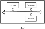
- the receiving module may be implemented by a receiver; the sending module may be implemented by a transmitter; and other modules such as the detection module and the detection module may be implemented by a processor. Functions corresponding to steps in another method procedure may be implemented by a processor.
- a corresponding function module performs a corresponding step in the method embodiments.
- the network device may be a base station, or another network device such as a transmission reception point TRP. This is not limited in the embodiments of the present invention.
- components of the device in FIG. 7 are coupled together by using a bus system, and the bus system includes a power bus, a control bus, and a status signal bus in addition to a data bus.
- the bus system includes a power bus, a control bus, and a status signal bus in addition to a data bus.
- the processor may be a central processing unit (Central Processing Unit, "CPU” for short), or another general purpose processor, a digital signal processor (DSP), an application-specific integrated circuit (ASIC), a field-programmable gate array (FPGA), or another programmable logic device, discrete gate or transistor logic device, discrete hardware component, or the like.
- the general purpose processor may be a microprocessor, or any conventional processor or the like.
- the memory may include a read-only memory and a random access memory, and provide an instruction and data for the processor.
- Apart of the memory may further include a non-volatile random access memory.
- the memory may further store information about a device type.
- the bus system may further include a power bus, a control bus, a status signal bus, and the like, in addition to a data bus.
- a power bus may further include a power bus, a control bus, a status signal bus, and the like, in addition to a data bus.
- various types of buses in the figure are marked as the bus system.
- sequence numbers of the foregoing processes do not mean execution sequences in the embodiments of the present invention.
- the execution sequences of the processes should be determined according to functions and internal logic of the processes, and should not be construed as any limitation on the implementation processes of the embodiments of the present invention.
- the disclosed system, apparatus, and method may be implemented in other manners.
- the described apparatus embodiment is merely an example.
- the unit division is merely logical function division and may be other division in actual implementation.
- a plurality of units or components may be combined or integrated into another system, or some features may be ignored or not performed.
- the displayed or discussed mutual couplings or direct couplings or communication connections may be implemented through some interfaces.
- the indirect couplings or communication connections between the apparatuses or units may be implemented in electronic, mechanical, or other forms.
- the units described as separate parts may or may not be physically separate, and parts displayed as units may or may not be physical units, may be located in one position, or may be distributed on a plurality of network units. Some or all of the units may be selected based on actual requirements to achieve the objectives of the solutions of the embodiments.
- function units in the embodiments of the present invention may be integrated into one processing unit, or each of the units may exist alone physically, or two or more units are integrated into one unit.
- the functions When the functions are implemented in a form of a software function unit and sold or used as an independent product, the functions may be stored in a computer-readable storage medium. Based on such an understanding, the technical solutions of the present invention essentially, or the part contributing to the prior art, or some of the technical solutions may be implemented in a form of a software product.
- the computer software product is stored in a storage medium, and includes instructions for instructing a computer device (which may be a personal computer, a server, or a network device) to perform all or some of the steps of the methods described in the embodiments of the present invention.
- the foregoing storage medium includes: any medium that can store program code, such as a USB flash drive, a removable hard disk, a read-only memory (ROM, Read-Only Memory), a random access memory (RAM, Random Access Memory), a magnetic disk, or an optical disc.
- program code such as a USB flash drive, a removable hard disk, a read-only memory (ROM, Read-Only Memory), a random access memory (RAM, Random Access Memory), a magnetic disk, or an optical disc.
Landscapes
- Engineering & Computer Science (AREA)
- Signal Processing (AREA)
- Computer Networks & Wireless Communication (AREA)
- Mobile Radio Communication Systems (AREA)
- Quality & Reliability (AREA)
- Physics & Mathematics (AREA)
- Electromagnetism (AREA)
Claims (12)
- Verfahren zum Senden eines Messsignals, umfassend:Senden (301) von Downlink-Messsignalen durch eine Netzwerkvorrichtung an eine Endgerätvorrichtung unter Verwendung eines oder mehrerer Übertragungsstrahlen; undEmpfangen eines Erkennungsergebnisses, das durch die Endgerätvorrichtung rückgemeldet wird, der Signalstärke der Downlink-Messsignale durch die Netzwerkvorrichtung;dadurch gekennzeichnet, dass das Verfahren ferner Folgendes umfasst:
wenn durch die Netzwerkvorrichtung bestimmt wird, dass die Endgerätvorrichtung in einen Zellenrandbereich der Netzwerkvorrichtung eintritt, indem erkannt wird, dass das Erkennungsergebnis niedriger als ein spezifizierter Schwellenwert ist, und wenn durch die Netzwerkvorrichtung bestimmt wird, dass eine Anzahl an Endgerätvorrichtungen, die in den Zellenrandbereich eintreten, geringer ist als eine Anzahl an benachbarten Basisstationen, Anweisen (303) der Endgerätvorrichtung durch die Netzwerkvorrichtung, eine auf dem Uplink-Messsignal basierende Messweise zu verwenden. - Verfahren gemäß Anspruch 1, wobei das Erkennungsergebnis der Signalstärke der Downlink-Messsignale ein Durchschnittswert oder ein größter Wert der Signalstärke von Downlink-Messsignalen einer Vielzahl von Übertragungsstrahlen ist.
- Verfahren gemäß Anspruch 1, ferner umfassend: Empfangen von Uplink-Messsignalen, die durch die Endgerätvorrichtung unter Verwendung eines oder mehrerer Strahlen gesendet werden.
- Verfahren zum Empfangen eines Messsignals, umfassend:Empfangen von Downlink-Messsignalen durch eine Endgerätvorrichtung, die durch eine Netzwerkvorrichtung unter Verwendung eines oder mehrerer Strahlen gesendet werden; undErkennen (302) der Signalstärke der Downlink-Messsignale und Rückmelden eines Erkennungsergebnisses an die Netzwerkvorrichtung durch die Endgerätvorrichtung;dadurch gekennzeichnet, dass das Verfahren ferner Folgendes umfasst:
wenn die Netzwerkvorrichtung bestimmt, dass die Endgerätvorrichtung in einen Zellenrandbereich der Netzwerkvorrichtung eintritt, indem erkannt wird, dass das durch die Endgerätvorrichtung rückgemeldete Erkennungsergebnis der Downlink-Messsignale niedriger ist als ein spezifizierter Schwellenwert, und die Netzwerkvorrichtung bestimmt, dass eine Anzahl an Endgerätvorrichtungen, die in den Zellenrandbereich eintreten, geringer ist als eine Anzahl an benachbarten Basisstationen, Empfangen einer Benachrichtigung durch die Endgerätvorrichtung, die durch die Netzwerkvorrichtung gesendet wird und die anzeigt, eine auf dem Uplink-Messsignal basierende Messweise zu verwenden. - Verfahren gemäß Anspruch 4, wobei das Erkennungsergebnis der Signalstärke der Downlink-Messsignale ein Durchschnittswert oder ein größter Wert der Signalstärke von Downlink-Messsignalen einer Vielzahl von Übertragungsstrahlen ist.
- Verfahren gemäß Anspruch 4, ferner umfassend: Senden von Uplink-Messsignalen durch die Endgerätvorrichtung an die Netzwerkvorrichtung unter Verwendung eines oder mehrerer Strahlen.
- Verfahren gemäß einem der Ansprüche 4 bis 6, wobei das Erkennen der Signalstärke der Downlink-Messsignale durch die Endgerätvorrichtung und das Rückmelden eines Erkennungsergebnisses an die Netzwerkvorrichtung spezifisch Folgendes umfasst:Messen von den Downlink-Messsignalen entsprechenden Anschlüssen durch die Endgerätvorrichtung, um Messindikatoren der Anschlüsse zu erlangen, und Senden der Messindikatoren der Anschlüsse an die Netzwerkvorrichtung; oderMessen der den Downlink-Messsignalen entsprechenden Strahlen durch die Endgerätvorrichtung, um Messindikatoren der Strahlen zu erlangen, und Senden der Messindikatoren der Strahlen an die Netzwerkvorrichtung.
- Verfahren gemäß einem der Ansprüche 1 bis 7, wobei das Uplink-Messsignal ein Uplink-Referenzsignal oder ein Uplink-Verfolgungssignal ist.
- Verfahren gemäß einem der Ansprüche 1 bis 8, wobei die Downlink-Messsignale Downlink-Referenzsignale, Referenzsignale für Kanalzustandsinformationen oder Messreferenzsignale sind.
- Netzwerkvorrichtung, umfassend ein oder mehrere Module, die dazu konfiguriert sind, einen der Ansprüche 1, 2, 3, 8 oder 9 umzusetzen.
- System, umfassend die Netzwerkvorrichtung gemäß Anspruch 10 und eine Endgerätvorrichtung, wobei die Endgerätvorrichtung ein oder mehrere Module umfasst, die dazu konfiguriert sind, das Verfahren gemäß einem der Ansprüche 4 bis 9 umzusetzen.
- Computerlesbares Speichermedium, umfassend Anweisungen, die, wenn sie von einem Computer ausgeführt werden, den Computer veranlassen, das Verfahren gemäß einem der Ansprüche 1 bis 3 oder das Verfahren gemäß Anspruch 8 oder 9 in Abhängigkeit von einem der Ansprüche 1 bis 3 durchzuführen.
Applications Claiming Priority (2)
| Application Number | Priority Date | Filing Date | Title |
|---|---|---|---|
| CN201710002460.1A CN108271177B (zh) | 2017-01-03 | 2017-01-03 | 一种测量信号的传输方法及装置 |
| PCT/CN2017/100293 WO2018126722A1 (zh) | 2017-01-03 | 2017-09-02 | 一种测量信号的传输方法及装置 |
Publications (3)
| Publication Number | Publication Date |
|---|---|
| EP3528528A1 EP3528528A1 (de) | 2019-08-21 |
| EP3528528A4 EP3528528A4 (de) | 2019-10-30 |
| EP3528528B1 true EP3528528B1 (de) | 2024-11-06 |
Family
ID=62771434
Family Applications (1)
| Application Number | Title | Priority Date | Filing Date |
|---|---|---|---|
| EP17890622.8A Active EP3528528B1 (de) | 2017-01-03 | 2017-09-02 | Verfahren und vorrichtung zur übertragung eines messsignals |
Country Status (4)
| Country | Link |
|---|---|
| US (1) | US20190280786A1 (de) |
| EP (1) | EP3528528B1 (de) |
| CN (1) | CN108271177B (de) |
| WO (1) | WO2018126722A1 (de) |
Families Citing this family (3)
| Publication number | Priority date | Publication date | Assignee | Title |
|---|---|---|---|---|
| US10313070B2 (en) * | 2016-11-03 | 2019-06-04 | Futurewei Technologies, Inc. | Fast millimeter-wave cell acquisition |
| CN108964863B (zh) * | 2017-01-05 | 2019-08-27 | 华为技术有限公司 | 一种上行测量信号的指示方法及装置 |
| US20240012084A1 (en) * | 2020-10-14 | 2024-01-11 | Qualcomm Incorporated | Hierarchical ue positioning |
Family Cites Families (12)
| Publication number | Priority date | Publication date | Assignee | Title |
|---|---|---|---|---|
| CN101237685B (zh) * | 2007-01-30 | 2011-12-14 | 诺基亚西门子通信系统技术(北京)有限公司 | 一种无线通信中的路由改变方法 |
| CN101494888B (zh) * | 2008-01-22 | 2010-12-08 | 中兴通讯股份有限公司 | 基于业务量的信道迁移方法 |
| CN102572879B (zh) * | 2011-12-28 | 2015-07-08 | 华为技术有限公司 | 通信方法、装置及系统 |
| US9398483B2 (en) * | 2012-06-19 | 2016-07-19 | Telefonaktiebolaget Lm Ericsson (Publ) | Method and controlling node for controlling measurements by a user equipment |
| CN103906120A (zh) * | 2012-12-27 | 2014-07-02 | 上海贝尔股份有限公司 | 多点协作测量集的配置方法与装置 |
| CN104349446B (zh) * | 2013-07-24 | 2018-12-07 | 中国移动通信集团设计院有限公司 | 一种上行功率控制方法及装置 |
| CN105207705A (zh) * | 2014-06-23 | 2015-12-30 | 北京三星通信技术研究有限公司 | 有源天线系统中的参考信号收发方法及设备 |
| US9768847B2 (en) * | 2014-07-02 | 2017-09-19 | Telefonaktiebolaget Lm Ericsson (Publ) | Methods and network nodes for enabling accurate measurements |
| CN105682154A (zh) * | 2014-11-20 | 2016-06-15 | 中兴通讯股份有限公司 | 一种小区切换方法及系统 |
| CN105828438B (zh) * | 2015-01-04 | 2019-06-25 | 中国移动通信集团公司 | 一种参考信号的配置方法、装置、基站和用户设备 |
| US10063395B2 (en) * | 2015-01-05 | 2018-08-28 | Lg Electronics Inc. | Method for estimating channel status in wireless communication system, and apparatus therefor |
| US20170230869A1 (en) * | 2016-02-10 | 2017-08-10 | Qualcomm Incorporated | Beam selection for uplink and downlink based mobility |
-
2017
- 2017-01-03 CN CN201710002460.1A patent/CN108271177B/zh active Active
- 2017-09-02 EP EP17890622.8A patent/EP3528528B1/de active Active
- 2017-09-02 WO PCT/CN2017/100293 patent/WO2018126722A1/zh not_active Ceased
-
2019
- 2019-05-23 US US16/420,863 patent/US20190280786A1/en not_active Abandoned
Also Published As
| Publication number | Publication date |
|---|---|
| CN108271177B (zh) | 2022-02-18 |
| EP3528528A4 (de) | 2019-10-30 |
| WO2018126722A1 (zh) | 2018-07-12 |
| CN108271177A (zh) | 2018-07-10 |
| US20190280786A1 (en) | 2019-09-12 |
| EP3528528A1 (de) | 2019-08-21 |
Similar Documents
| Publication | Publication Date | Title |
|---|---|---|
| US11716640B2 (en) | Method, apparatus, and computer-readable medium for providing synchronization signal block (SSB) transmission pattern | |
| US11070264B2 (en) | Downlink-beam adjustment method and apparatus | |
| US10862652B2 (en) | Uplink signal acknowledge method and apparatus | |
| CN108353330B (zh) | 用于实现移动性过程的方法和节点 | |
| EP3381214B1 (de) | Drahtlose vorrichtung, funknetzknoten und darin durchgeführte verfahren zur signalisierungsverwaltung in einem drahtloskommunikationsnetzwerk | |
| JP2017011748A (ja) | 基準信号受信品質(rsrq)を使用するハンドオーバ向上のためのユーザ機器 | |
| CN117914372A (zh) | 移动终端、基站及其方法 | |
| EP3563492B1 (de) | Funknetzknoten, drahtlose vorrichtung und darin ausgeführte verfahren zur kommunikation in einem drahtloskommunikationsnetzwerk | |
| CN109005548A (zh) | 一种信道质量信息的上报方法及装置 | |
| CN115767678A (zh) | 通信系统中的用户设备、网络及其所用的方法 | |
| US11202220B2 (en) | Method of adapting report mapping based on beamforming | |
| CN110100471B (zh) | 无线电网络节点以及在其中执行的用于处理无线通信网络中的通信的方法 | |
| US10827374B2 (en) | Resource management indication method and apparatus with flexible manner of measurement | |
| US20230354252A1 (en) | Positioning information transmission method and apparatus | |
| EP3528528B1 (de) | Verfahren und vorrichtung zur übertragung eines messsignals | |
| CN112291849A (zh) | 无线网络通信方法和通信装置 | |
| CN116980904A (zh) | 信息处理方法、网络侧设备及终端 | |
| EP4054243A1 (de) | Verfahren und vorrichtung zur verwaltung der zellenübergabe und speichermedium | |
| US11870526B2 (en) | Wireless communication method and apparatus, device, and storage medium |
Legal Events
| Date | Code | Title | Description |
|---|---|---|---|
| STAA | Information on the status of an ep patent application or granted ep patent |
Free format text: STATUS: THE INTERNATIONAL PUBLICATION HAS BEEN MADE |
|
| PUAI | Public reference made under article 153(3) epc to a published international application that has entered the european phase |
Free format text: ORIGINAL CODE: 0009012 |
|
| STAA | Information on the status of an ep patent application or granted ep patent |
Free format text: STATUS: REQUEST FOR EXAMINATION WAS MADE |
|
| 17P | Request for examination filed |
Effective date: 20190517 |
|
| AK | Designated contracting states |
Kind code of ref document: A1 Designated state(s): AL AT BE BG CH CY CZ DE DK EE ES FI FR GB GR HR HU IE IS IT LI LT LU LV MC MK MT NL NO PL PT RO RS SE SI SK SM TR |
|
| AX | Request for extension of the european patent |
Extension state: BA ME |
|
| A4 | Supplementary search report drawn up and despatched |
Effective date: 20190927 |
|
| RIC1 | Information provided on ipc code assigned before grant |
Ipc: H04W 24/00 20090101AFI20190923BHEP Ipc: H04B 7/00 20060101ALI20190923BHEP |
|
| DAV | Request for validation of the european patent (deleted) | ||
| DAX | Request for extension of the european patent (deleted) | ||
| STAA | Information on the status of an ep patent application or granted ep patent |
Free format text: STATUS: EXAMINATION IS IN PROGRESS |
|
| 17Q | First examination report despatched |
Effective date: 20210317 |
|
| GRAP | Despatch of communication of intention to grant a patent |
Free format text: ORIGINAL CODE: EPIDOSNIGR1 |
|
| STAA | Information on the status of an ep patent application or granted ep patent |
Free format text: STATUS: GRANT OF PATENT IS INTENDED |
|
| INTG | Intention to grant announced |
Effective date: 20240415 |
|
| GRAS | Grant fee paid |
Free format text: ORIGINAL CODE: EPIDOSNIGR3 |
|
| GRAA | (expected) grant |
Free format text: ORIGINAL CODE: 0009210 |
|
| STAA | Information on the status of an ep patent application or granted ep patent |
Free format text: STATUS: THE PATENT HAS BEEN GRANTED |
|
| AK | Designated contracting states |
Kind code of ref document: B1 Designated state(s): AL AT BE BG CH CY CZ DE DK EE ES FI FR GB GR HR HU IE IS IT LI LT LU LV MC MK MT NL NO PL PT RO RS SE SI SK SM TR |
|
| REG | Reference to a national code |
Ref country code: GB Ref legal event code: FG4D |
|
| REG | Reference to a national code |
Ref country code: CH Ref legal event code: EP |
|
| REG | Reference to a national code |
Ref country code: DE Ref legal event code: R096 Ref document number: 602017086016 Country of ref document: DE |
|
| REG | Reference to a national code |
Ref country code: IE Ref legal event code: FG4D |
|
| REG | Reference to a national code |
Ref country code: LT Ref legal event code: MG9D |
|
| REG | Reference to a national code |
Ref country code: NL Ref legal event code: MP Effective date: 20241106 |
|
| PG25 | Lapsed in a contracting state [announced via postgrant information from national office to epo] |
Ref country code: PT Free format text: LAPSE BECAUSE OF FAILURE TO SUBMIT A TRANSLATION OF THE DESCRIPTION OR TO PAY THE FEE WITHIN THE PRESCRIBED TIME-LIMIT Effective date: 20250306 Ref country code: HR Free format text: LAPSE BECAUSE OF FAILURE TO SUBMIT A TRANSLATION OF THE DESCRIPTION OR TO PAY THE FEE WITHIN THE PRESCRIBED TIME-LIMIT Effective date: 20241106 Ref country code: IS Free format text: LAPSE BECAUSE OF FAILURE TO SUBMIT A TRANSLATION OF THE DESCRIPTION OR TO PAY THE FEE WITHIN THE PRESCRIBED TIME-LIMIT Effective date: 20250306 |
|
| PG25 | Lapsed in a contracting state [announced via postgrant information from national office to epo] |
Ref country code: NL Free format text: LAPSE BECAUSE OF FAILURE TO SUBMIT A TRANSLATION OF THE DESCRIPTION OR TO PAY THE FEE WITHIN THE PRESCRIBED TIME-LIMIT Effective date: 20241106 Ref country code: FI Free format text: LAPSE BECAUSE OF FAILURE TO SUBMIT A TRANSLATION OF THE DESCRIPTION OR TO PAY THE FEE WITHIN THE PRESCRIBED TIME-LIMIT Effective date: 20241106 |
|
| REG | Reference to a national code |
Ref country code: AT Ref legal event code: MK05 Ref document number: 1740744 Country of ref document: AT Kind code of ref document: T Effective date: 20241106 |
|
| PG25 | Lapsed in a contracting state [announced via postgrant information from national office to epo] |
Ref country code: BG Free format text: LAPSE BECAUSE OF FAILURE TO SUBMIT A TRANSLATION OF THE DESCRIPTION OR TO PAY THE FEE WITHIN THE PRESCRIBED TIME-LIMIT Effective date: 20241106 |
|
| PG25 | Lapsed in a contracting state [announced via postgrant information from national office to epo] |
Ref country code: ES Free format text: LAPSE BECAUSE OF FAILURE TO SUBMIT A TRANSLATION OF THE DESCRIPTION OR TO PAY THE FEE WITHIN THE PRESCRIBED TIME-LIMIT Effective date: 20241106 |
|
| PG25 | Lapsed in a contracting state [announced via postgrant information from national office to epo] |
Ref country code: NO Free format text: LAPSE BECAUSE OF FAILURE TO SUBMIT A TRANSLATION OF THE DESCRIPTION OR TO PAY THE FEE WITHIN THE PRESCRIBED TIME-LIMIT Effective date: 20250206 |
|
| PG25 | Lapsed in a contracting state [announced via postgrant information from national office to epo] |
Ref country code: AT Free format text: LAPSE BECAUSE OF FAILURE TO SUBMIT A TRANSLATION OF THE DESCRIPTION OR TO PAY THE FEE WITHIN THE PRESCRIBED TIME-LIMIT Effective date: 20241106 Ref country code: GR Free format text: LAPSE BECAUSE OF FAILURE TO SUBMIT A TRANSLATION OF THE DESCRIPTION OR TO PAY THE FEE WITHIN THE PRESCRIBED TIME-LIMIT Effective date: 20250207 Ref country code: LV Free format text: LAPSE BECAUSE OF FAILURE TO SUBMIT A TRANSLATION OF THE DESCRIPTION OR TO PAY THE FEE WITHIN THE PRESCRIBED TIME-LIMIT Effective date: 20241106 |
|
| PG25 | Lapsed in a contracting state [announced via postgrant information from national office to epo] |
Ref country code: PL Free format text: LAPSE BECAUSE OF FAILURE TO SUBMIT A TRANSLATION OF THE DESCRIPTION OR TO PAY THE FEE WITHIN THE PRESCRIBED TIME-LIMIT Effective date: 20241106 |
|
| PG25 | Lapsed in a contracting state [announced via postgrant information from national office to epo] |
Ref country code: RS Free format text: LAPSE BECAUSE OF FAILURE TO SUBMIT A TRANSLATION OF THE DESCRIPTION OR TO PAY THE FEE WITHIN THE PRESCRIBED TIME-LIMIT Effective date: 20250206 |
|
| PG25 | Lapsed in a contracting state [announced via postgrant information from national office to epo] |
Ref country code: SM Free format text: LAPSE BECAUSE OF FAILURE TO SUBMIT A TRANSLATION OF THE DESCRIPTION OR TO PAY THE FEE WITHIN THE PRESCRIBED TIME-LIMIT Effective date: 20241106 |
|
| PG25 | Lapsed in a contracting state [announced via postgrant information from national office to epo] |
Ref country code: DK Free format text: LAPSE BECAUSE OF FAILURE TO SUBMIT A TRANSLATION OF THE DESCRIPTION OR TO PAY THE FEE WITHIN THE PRESCRIBED TIME-LIMIT Effective date: 20241106 |
|
| PG25 | Lapsed in a contracting state [announced via postgrant information from national office to epo] |
Ref country code: EE Free format text: LAPSE BECAUSE OF FAILURE TO SUBMIT A TRANSLATION OF THE DESCRIPTION OR TO PAY THE FEE WITHIN THE PRESCRIBED TIME-LIMIT Effective date: 20241106 |
|
| PG25 | Lapsed in a contracting state [announced via postgrant information from national office to epo] |
Ref country code: RO Free format text: LAPSE BECAUSE OF FAILURE TO SUBMIT A TRANSLATION OF THE DESCRIPTION OR TO PAY THE FEE WITHIN THE PRESCRIBED TIME-LIMIT Effective date: 20241106 |
|
| PG25 | Lapsed in a contracting state [announced via postgrant information from national office to epo] |
Ref country code: SK Free format text: LAPSE BECAUSE OF FAILURE TO SUBMIT A TRANSLATION OF THE DESCRIPTION OR TO PAY THE FEE WITHIN THE PRESCRIBED TIME-LIMIT Effective date: 20241106 |
|
| PG25 | Lapsed in a contracting state [announced via postgrant information from national office to epo] |
Ref country code: CZ Free format text: LAPSE BECAUSE OF FAILURE TO SUBMIT A TRANSLATION OF THE DESCRIPTION OR TO PAY THE FEE WITHIN THE PRESCRIBED TIME-LIMIT Effective date: 20241106 |
|
| PG25 | Lapsed in a contracting state [announced via postgrant information from national office to epo] |
Ref country code: IT Free format text: LAPSE BECAUSE OF FAILURE TO SUBMIT A TRANSLATION OF THE DESCRIPTION OR TO PAY THE FEE WITHIN THE PRESCRIBED TIME-LIMIT Effective date: 20241106 |
|
| REG | Reference to a national code |
Ref country code: DE Ref legal event code: R097 Ref document number: 602017086016 Country of ref document: DE |
|
| PG25 | Lapsed in a contracting state [announced via postgrant information from national office to epo] |
Ref country code: SE Free format text: LAPSE BECAUSE OF FAILURE TO SUBMIT A TRANSLATION OF THE DESCRIPTION OR TO PAY THE FEE WITHIN THE PRESCRIBED TIME-LIMIT Effective date: 20241106 |
|
| PLBE | No opposition filed within time limit |
Free format text: ORIGINAL CODE: 0009261 |
|
| STAA | Information on the status of an ep patent application or granted ep patent |
Free format text: STATUS: NO OPPOSITION FILED WITHIN TIME LIMIT |
|
| PGFP | Annual fee paid to national office [announced via postgrant information from national office to epo] |
Ref country code: DE Payment date: 20250730 Year of fee payment: 9 |
|
| 26N | No opposition filed |
Effective date: 20250807 |
|
| PGFP | Annual fee paid to national office [announced via postgrant information from national office to epo] |
Ref country code: GB Payment date: 20250731 Year of fee payment: 9 |
|
| REG | Reference to a national code |
Ref country code: CH Ref legal event code: H13 Free format text: ST27 STATUS EVENT CODE: U-0-0-H10-H13 (AS PROVIDED BY THE NATIONAL OFFICE) Effective date: 20260425 |