EP3528309A1 - An arrangement for assembling rechargeable battery units into a battery module and a battery module - Google Patents
An arrangement for assembling rechargeable battery units into a battery module and a battery module Download PDFInfo
- Publication number
- EP3528309A1 EP3528309A1 EP19155067.2A EP19155067A EP3528309A1 EP 3528309 A1 EP3528309 A1 EP 3528309A1 EP 19155067 A EP19155067 A EP 19155067A EP 3528309 A1 EP3528309 A1 EP 3528309A1
- Authority
- EP
- European Patent Office
- Prior art keywords
- arrangement
- battery
- base plate
- battery unit
- cover plate
- Prior art date
- Legal status (The legal status is an assumption and is not a legal conclusion. Google has not performed a legal analysis and makes no representation as to the accuracy of the status listed.)
- Pending
Links
Images


Classifications
-
- H—ELECTRICITY
- H01—ELECTRIC ELEMENTS
- H01M—PROCESSES OR MEANS, e.g. BATTERIES, FOR THE DIRECT CONVERSION OF CHEMICAL ENERGY INTO ELECTRICAL ENERGY
- H01M50/00—Constructional details or processes of manufacture of the non-active parts of electrochemical cells other than fuel cells, e.g. hybrid cells
- H01M50/20—Mountings; Secondary casings or frames; Racks, modules or packs; Suspension devices; Shock absorbers; Transport or carrying devices; Holders
- H01M50/249—Mountings; Secondary casings or frames; Racks, modules or packs; Suspension devices; Shock absorbers; Transport or carrying devices; Holders specially adapted for aircraft or vehicles, e.g. cars or trains
-
- B—PERFORMING OPERATIONS; TRANSPORTING
- B60—VEHICLES IN GENERAL
- B60L—PROPULSION OF ELECTRICALLY-PROPELLED VEHICLES; SUPPLYING ELECTRIC POWER FOR AUXILIARY EQUIPMENT OF ELECTRICALLY-PROPELLED VEHICLES; ELECTRODYNAMIC BRAKE SYSTEMS FOR VEHICLES IN GENERAL; MAGNETIC SUSPENSION OR LEVITATION FOR VEHICLES; MONITORING OPERATING VARIABLES OF ELECTRICALLY-PROPELLED VEHICLES; ELECTRIC SAFETY DEVICES FOR ELECTRICALLY-PROPELLED VEHICLES
- B60L53/00—Methods of charging batteries, specially adapted for electric vehicles; Charging stations or on-board charging equipment therefor; Exchange of energy storage elements in electric vehicles
- B60L53/80—Exchanging energy storage elements, e.g. removable batteries
-
- B—PERFORMING OPERATIONS; TRANSPORTING
- B60—VEHICLES IN GENERAL
- B60L—PROPULSION OF ELECTRICALLY-PROPELLED VEHICLES; SUPPLYING ELECTRIC POWER FOR AUXILIARY EQUIPMENT OF ELECTRICALLY-PROPELLED VEHICLES; ELECTRODYNAMIC BRAKE SYSTEMS FOR VEHICLES IN GENERAL; MAGNETIC SUSPENSION OR LEVITATION FOR VEHICLES; MONITORING OPERATING VARIABLES OF ELECTRICALLY-PROPELLED VEHICLES; ELECTRIC SAFETY DEVICES FOR ELECTRICALLY-PROPELLED VEHICLES
- B60L50/00—Electric propulsion with power supplied within the vehicle
- B60L50/50—Electric propulsion with power supplied within the vehicle using propulsion power supplied by batteries or fuel cells
- B60L50/60—Electric propulsion with power supplied within the vehicle using propulsion power supplied by batteries or fuel cells using power supplied by batteries
- B60L50/64—Constructional details of batteries specially adapted for electric vehicles
-
- B—PERFORMING OPERATIONS; TRANSPORTING
- B60—VEHICLES IN GENERAL
- B60L—PROPULSION OF ELECTRICALLY-PROPELLED VEHICLES; SUPPLYING ELECTRIC POWER FOR AUXILIARY EQUIPMENT OF ELECTRICALLY-PROPELLED VEHICLES; ELECTRODYNAMIC BRAKE SYSTEMS FOR VEHICLES IN GENERAL; MAGNETIC SUSPENSION OR LEVITATION FOR VEHICLES; MONITORING OPERATING VARIABLES OF ELECTRICALLY-PROPELLED VEHICLES; ELECTRIC SAFETY DEVICES FOR ELECTRICALLY-PROPELLED VEHICLES
- B60L50/00—Electric propulsion with power supplied within the vehicle
- B60L50/50—Electric propulsion with power supplied within the vehicle using propulsion power supplied by batteries or fuel cells
- B60L50/60—Electric propulsion with power supplied within the vehicle using propulsion power supplied by batteries or fuel cells using power supplied by batteries
- B60L50/66—Arrangements of batteries
-
- H—ELECTRICITY
- H01—ELECTRIC ELEMENTS
- H01M—PROCESSES OR MEANS, e.g. BATTERIES, FOR THE DIRECT CONVERSION OF CHEMICAL ENERGY INTO ELECTRICAL ENERGY
- H01M10/00—Secondary cells; Manufacture thereof
- H01M10/05—Accumulators with non-aqueous electrolyte
- H01M10/052—Li-accumulators
-
- H—ELECTRICITY
- H01—ELECTRIC ELEMENTS
- H01M—PROCESSES OR MEANS, e.g. BATTERIES, FOR THE DIRECT CONVERSION OF CHEMICAL ENERGY INTO ELECTRICAL ENERGY
- H01M10/00—Secondary cells; Manufacture thereof
- H01M10/05—Accumulators with non-aqueous electrolyte
- H01M10/052—Li-accumulators
- H01M10/0525—Rocking-chair batteries, i.e. batteries with lithium insertion or intercalation in both electrodes; Lithium-ion batteries
-
- H—ELECTRICITY
- H01—ELECTRIC ELEMENTS
- H01M—PROCESSES OR MEANS, e.g. BATTERIES, FOR THE DIRECT CONVERSION OF CHEMICAL ENERGY INTO ELECTRICAL ENERGY
- H01M50/00—Constructional details or processes of manufacture of the non-active parts of electrochemical cells other than fuel cells, e.g. hybrid cells
- H01M50/20—Mountings; Secondary casings or frames; Racks, modules or packs; Suspension devices; Shock absorbers; Transport or carrying devices; Holders
- H01M50/204—Racks, modules or packs for multiple batteries or multiple cells
-
- H—ELECTRICITY
- H01—ELECTRIC ELEMENTS
- H01M—PROCESSES OR MEANS, e.g. BATTERIES, FOR THE DIRECT CONVERSION OF CHEMICAL ENERGY INTO ELECTRICAL ENERGY
- H01M50/00—Constructional details or processes of manufacture of the non-active parts of electrochemical cells other than fuel cells, e.g. hybrid cells
- H01M50/20—Mountings; Secondary casings or frames; Racks, modules or packs; Suspension devices; Shock absorbers; Transport or carrying devices; Holders
- H01M50/233—Mountings; Secondary casings or frames; Racks, modules or packs; Suspension devices; Shock absorbers; Transport or carrying devices; Holders characterised by physical properties of casings or racks, e.g. dimensions
-
- H—ELECTRICITY
- H01—ELECTRIC ELEMENTS
- H01M—PROCESSES OR MEANS, e.g. BATTERIES, FOR THE DIRECT CONVERSION OF CHEMICAL ENERGY INTO ELECTRICAL ENERGY
- H01M50/00—Constructional details or processes of manufacture of the non-active parts of electrochemical cells other than fuel cells, e.g. hybrid cells
- H01M50/20—Mountings; Secondary casings or frames; Racks, modules or packs; Suspension devices; Shock absorbers; Transport or carrying devices; Holders
- H01M50/271—Lids or covers for the racks or secondary casings
-
- H—ELECTRICITY
- H01—ELECTRIC ELEMENTS
- H01M—PROCESSES OR MEANS, e.g. BATTERIES, FOR THE DIRECT CONVERSION OF CHEMICAL ENERGY INTO ELECTRICAL ENERGY
- H01M50/00—Constructional details or processes of manufacture of the non-active parts of electrochemical cells other than fuel cells, e.g. hybrid cells
- H01M50/50—Current conducting connections for cells or batteries
- H01M50/502—Interconnectors for connecting terminals of adjacent batteries; Interconnectors for connecting cells outside a battery casing
- H01M50/514—Methods for interconnecting adjacent batteries or cells
- H01M50/517—Methods for interconnecting adjacent batteries or cells by fixing means, e.g. screws, rivets or bolts
-
- H—ELECTRICITY
- H01—ELECTRIC ELEMENTS
- H01M—PROCESSES OR MEANS, e.g. BATTERIES, FOR THE DIRECT CONVERSION OF CHEMICAL ENERGY INTO ELECTRICAL ENERGY
- H01M2220/00—Batteries for particular applications
- H01M2220/20—Batteries in motive systems, e.g. vehicle, ship, plane
-
- H—ELECTRICITY
- H01—ELECTRIC ELEMENTS
- H01M—PROCESSES OR MEANS, e.g. BATTERIES, FOR THE DIRECT CONVERSION OF CHEMICAL ENERGY INTO ELECTRICAL ENERGY
- H01M50/00—Constructional details or processes of manufacture of the non-active parts of electrochemical cells other than fuel cells, e.g. hybrid cells
- H01M50/50—Current conducting connections for cells or batteries
- H01M50/502—Interconnectors for connecting terminals of adjacent batteries; Interconnectors for connecting cells outside a battery casing
- H01M50/509—Interconnectors for connecting terminals of adjacent batteries; Interconnectors for connecting cells outside a battery casing characterised by the type of connection, e.g. mixed connections
- H01M50/51—Connection only in series
-
- Y—GENERAL TAGGING OF NEW TECHNOLOGICAL DEVELOPMENTS; GENERAL TAGGING OF CROSS-SECTIONAL TECHNOLOGIES SPANNING OVER SEVERAL SECTIONS OF THE IPC; TECHNICAL SUBJECTS COVERED BY FORMER USPC CROSS-REFERENCE ART COLLECTIONS [XRACs] AND DIGESTS
- Y02—TECHNOLOGIES OR APPLICATIONS FOR MITIGATION OR ADAPTATION AGAINST CLIMATE CHANGE
- Y02E—REDUCTION OF GREENHOUSE GAS [GHG] EMISSIONS, RELATED TO ENERGY GENERATION, TRANSMISSION OR DISTRIBUTION
- Y02E60/00—Enabling technologies; Technologies with a potential or indirect contribution to GHG emissions mitigation
- Y02E60/10—Energy storage using batteries
-
- Y—GENERAL TAGGING OF NEW TECHNOLOGICAL DEVELOPMENTS; GENERAL TAGGING OF CROSS-SECTIONAL TECHNOLOGIES SPANNING OVER SEVERAL SECTIONS OF THE IPC; TECHNICAL SUBJECTS COVERED BY FORMER USPC CROSS-REFERENCE ART COLLECTIONS [XRACs] AND DIGESTS
- Y02—TECHNOLOGIES OR APPLICATIONS FOR MITIGATION OR ADAPTATION AGAINST CLIMATE CHANGE
- Y02T—CLIMATE CHANGE MITIGATION TECHNOLOGIES RELATED TO TRANSPORTATION
- Y02T10/00—Road transport of goods or passengers
- Y02T10/60—Other road transportation technologies with climate change mitigation effect
- Y02T10/70—Energy storage systems for electromobility, e.g. batteries
-
- Y—GENERAL TAGGING OF NEW TECHNOLOGICAL DEVELOPMENTS; GENERAL TAGGING OF CROSS-SECTIONAL TECHNOLOGIES SPANNING OVER SEVERAL SECTIONS OF THE IPC; TECHNICAL SUBJECTS COVERED BY FORMER USPC CROSS-REFERENCE ART COLLECTIONS [XRACs] AND DIGESTS
- Y02—TECHNOLOGIES OR APPLICATIONS FOR MITIGATION OR ADAPTATION AGAINST CLIMATE CHANGE
- Y02T—CLIMATE CHANGE MITIGATION TECHNOLOGIES RELATED TO TRANSPORTATION
- Y02T10/00—Road transport of goods or passengers
- Y02T10/60—Other road transportation technologies with climate change mitigation effect
- Y02T10/7072—Electromobility specific charging systems or methods for batteries, ultracapacitors, supercapacitors or double-layer capacitors
Definitions
- the present disclosure relates to an arrangement for assembling rechargeable battery units into a battery module.
- the present disclosure also relates to a battery module comprising at least two battery units and an arrangement for assembling said rechargeable battery units into a battery module.
- Rechargeable Li-ion batteries are becoming an increasingly used electrical source for propelling lift-trucks due to their relatively short recharging time.
- the rechargeable Li-ion batteries are typically provided in the form of small individual cylinders that are stacked in a container and form a battery unit.
- the maximum voltage of each battery unit is limited and therefore it is necessary to electrically connect several battery units to each other in order to achieve a working voltage suitable for the lift truck.
- lift-trucks run on a working voltage of 24 V or 48V.
- US20170170438 shows a battery module in the form of a box in which several individual battery units are placed. Each battery unit has a vertical flange with openings that makes it possible to bolt the battery units to partition walls in the box. Separate and not further disclosed electrical connection are provided to electrically interconnect the battery units.
- the arrangement disclosed in US20170170438 is marred with drawbacks. For example, the process of gather battery units in a box and subsequently bolt the battery units to the partition walls of the box and then electrically interconnect the battery units is cumbersome and work intensive. Also, since the battery units are collected in a box the maximum voltage as well as the geometrical design of the battery module is limited to specific applications.
- the arrangement for assembling rechargeable battery units 10 provides a simple solution for assembling a plurality of pre-manufactured rechargeable battery units into a battery module .
- the claimed arrangement is very suitable for manual assembly of battery modules since it only requires a minimum of working steps to assemble the battery unit.
- the person assembling the battery modules needs only to place the battery units onto the base plate, apply the cover plate on top of the respective battery units and subsequently interlock the base plate and the cover plate with the connection means. Electrical series connection of the battery units is achieved when the cover plate is applied onto the tops of the battery units.
- the base plate 110 is rectangular and has a width (W) and a length (L), whereby the width (W) of the base plate (100 is substantially equal to or less than the width (w) of each battery unit 10.
- W width
- L length
- the width (W) of the base plate (100 is substantially equal to or less than the width (w) of each battery unit 10.
- the engagement means 113 comprises protrusions extending from the base plate 110 and configured to be received in corresponding recesses 20 provided in a bottom surface 19 of each battery unit 10.
- This provides a simple, yet effective way of fixating the battery units on to the upper surface of the base plate in order to prevent parallel movement between the base plate and the battery units.
- a person assembling the module may easily mount the battery unit on the base plate such that the protrusions of the base plate are received in the recesses in the bottom surface of the battery units.
- the protrusions 113 are arranged in a first and a second parallel row along the length (L) of the base plate 110. It is thereby advantageous that the bottom surface 19 of each battery unit 10 comprises at least a first and second recess 20 and that the number of protrusions 113 on the base plate 110 correspond to the total number of recesses 20 of the battery units 10. This makes it easy for a person to place the battery units in correct position on the base plate and the battery units are simultaneously prevented from rotating on the base plate by the provision of two recesses in each bottom surface.
- the arrangement for assembling battery units comprises a first and a second fastening means 150, 150 for attaching the cover plate 110 to the respective top 12 of each battery unit 10.
- the arrangement for assembling battery units will thereby be completely locked to all the battery units. As a consequence thereof any movement between the separate battery units and the components of the arrangement for assembling battery units is completely eliminated in all directions.
- the cover plate 130 comprises a first opening 133 for receiving a terminal 14, 15 of a first battery unit 10.1 and a second opening 134 for receiving a terminal 14, 15 of a second battery unit 10.2, wherein the electrical contact means 135 comprises electrically conductive sheet material 136 arranged around the respective first and the second opening 133, 134 and extending between the first and the second opening 133, 134.
- the first and the second fastening means 150, 150 may thereby be configured to clamp the electrically conductive sheet material 136 of the first and the second opening 133, 134 of the cover plate 130 to the respective terminal 14,15 of the first and second battery unit 10.1, 10.2. This provides an efficient way of locking the cover plate to the top of the battery units and simultaneous achieve electrical series connection of the battery units.
- the terminals 14, 15 of each battery unit 10 comprises a threaded bore 16 and a contact surface 17 and the fastening means 150 comprises a head 151 and a corresponding threaded portion 152 configured to be received in the threaded bore 16 of a terminal 14, 15 of a battery unit 10, such that the head 151 of the fastening means 150 is clamped against one side of the electrically conductive sheet material 136 of an opening 133, 134 and the contact surface 17 of the terminal 14,15 is clamped against the other side of the electrically conductive sheet material 136 of said opening 133, 134.
- the result thereof is a very strong attachment of the cover plate to the respective tops of the battery units and a secure electrical series connection of the battery units.
- the first and the second connection element 160, 160 comprises preferably an elongated central portion 161 and a first end flange 162 and a second end flange 163 and the base plate 110 and the cover plate 130 respectively comprises opposing first and second side edges 114; the base plate 110 and the cover plate 130 may thereby comprise, respectively, at least a first seat 115, 115 and second seat 139, 139 arranged opposite each other and having a respective opening 116, 140 in a respective one of the opposing side edges 114 of the base plate 110 and the cover plate 130.
- a respective first end flange 162 of the connection means 160 is configured to be attachable received in a seat 115 of the base plate 110 through the opening 116 of said seat 115 and a respective second end flange 163 of the connection means 160 is configured to be attachable received in a seat 139 of the cover plate 130 through the opening 14 of said seat 139.
- the advantage thereof is that the end flanges are easy to insert into the seats and that, in use, the end flanges are protected by the seats.
- the arrangement 100 for assembling battery units may also comprise a joining means 170 for joining the arrangement 100 for assembling battery units to another, identical, arrangement 100 for assembling rechargeable battery units 100. This allows for easy build-up of larger battery aggregates for lift-trucks that requires large supplies of electric power.
- the present disclosure also relates to a battery module 200 for a lift-truck comprising at least a first and a second rechargeable battery unit 10,1, 10.2 having a housing 11 with a bottom 18 and an opposing top 12 with a positive and a negative battery terminal 14, 15 and an arrangement 100 for assembling the at least first and second rechargeable battery units 10.1, 10. 2 into a battery module 200 said arrangement (100) comprises;
- the arrangement for assembling rechargeable battery units into a battery module for a lift-truck according to the present disclosure will now be described more fully hereinafter.
- the arrangement for assembling rechargeable battery units into a battery module for a lift-truck according to the present disclosure may however be embodied in many different forms and should not be construed as limited to the embodiment set forth herein. Rather, this embodiment is provided by way of example so that this disclosure will be thorough and complete, and will fully convey the scope of the present disclosure to those persons skilled in the art.
- the arrangement for assembling rechargeable battery units into a battery module for a lift-truck may be referred to as "the arrangement”.
- specific terms may be employed herein, they are used in a generic and descriptive sense only and not for purposes of limitation.
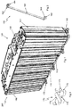
- FIG. 1 shows an exemplary embodiment of a battery module 200 comprising an arrangement 100 for assembling rechargeable battery units into a battery module for a lift-truck according to the present disclosure.
- the battery module 200 comprises seven battery units 10.
- the battery module 200 may comprise at least two battery units 10 or any suitable number of more than two battery units.
- the arrangement 100 comprises a base plate 110 for supporting the battery units 10 and a cover plate 130 configured to be arranged on top of the battery units 10 and connection means 160 that are arranged to interlock the cover plate 130 and the base plate 110.
- connection means 160 is attached to the base plate 110 and the other end of the connection means 160 is attached to the cover plate 130.
- two connection means 160 are provided on each longside of the arrangement 100.
- the arrangement 100 may further comprise a fastening means 150, such as threaded bolts, for attaching the cover plate 130 to the top of the battery units.
- the arrangement 100 may further comprise one or more joining means, 170 for joining the battery module 200 to another identical battery module (not shown).
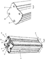
- FIG. 2 shows a connection means 160 which comprises an elongated central portion 161 and a first and second end flange 162, 163 that respectively extends perpendicular from the central portion 161.
- the first and second end flanges 162, 163 may comprise a respective opening 164 for receiving a screws or protrusion in order to attach the first and second end flanges 162, 163 to the base plate 110 and to the cover plate 130.
- the connection means 160 are narrow and elongated. Thus the width of the connection means 160 is less than the width or the length of the bottom surface 19 of a battery unit 10.
- connection means 160 is rigid an may be manufactured from metal, e.g. steel strip or hard plastic material.
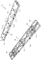
- FIG. 3 shows a joining means 170 which comprises a first and second locking body 171 arranged symmetrically on opposite sides of a bridging part 174.
- Each locking body 171 is connected to the bridging part by an extension portion 175 and comprises a stem 172 that extends perpendicular from the locking body 171 and that comprises a shoulder 173 at its end.
- FIG 4 shows a battery unit 10 which is configured to be assembled, together with at least one further identical battery unit, by an arrangement according to the present disclosure into a battery module for a lift-truck.
- the battery unit 10 comprises an elongated housing 11 of rectangular cross-section that has a closed top 12 and a closed bottom 18 having a length 1 and a width w.
- the top 12 comprises a flat top surface 13 and a positive battery terminal 14 (anode) and a negative battery terminal 15 (cathode).
- the battery terminals are spaced apart and oriented next to each other along the center of the top surface.
- the battery terminals 14, 15 protrude axially from the top surface 13 and comprises a central threaded bore 16 and an annular contact surface 17 arranged concentrically with the threaded bore 16.
- the housing 11 encloses rechargeable Lithium-ion batteries (not shown) that are electrically connected to the terminals 14, 15 of the battery unit 10.
- Figure 5 shows the bottom 18 of the battery unit 10 of figure 2 .
- the bottom 18 comprises a flat bottom surface 19 that is provided with engagement means in form of recesses 20.
- four recesses 20 are provided, spaced apart from each other, and oriented adjacent the corners of the rectangular bottom surface 19.
- the number of recesses 20 may be fewer than four, e.g. at least two recesses 20 may be provided in the bottom surface of the battery unit 10.
- FIG 6 shows the base plate 110 of the arrangement 100.
- the base plate 110 may be elongate and rectangular.
- the width W of the base plate 110 is substantially equal to the width w of bottom surface 19 of the battery unit 10 (see figure 4 ).
- the length L of the base plate 110 is substantially equal the combined length 1 of the bottom surfaces of the battery units 10 included in the battery module.
- the length L of the base plate 110 may be substantially equal the combined length 1 of the bottom surface 19 of at least two battery units 10.
- the base plate 110 has an upper surface 111 that is configured to support the bottom surfaces of 19 of at least two battery units 10. That is, at least two battery units 10 may be placed onto the upper surface 111 of the base plate 110.
- the upper surface 111 of the base plate 110 comprises engagement means 113 that are configured to fixate the position of the at least two battery units 10 onto the base plate 110.
- the engagement means 113 of the base plate 110 may be protrusions that extend axially from the upper surface 111 of the base plate 110. The protrusions 113 are configured to be received in the corresponding recesses 20 in the bottom surface 19 of the battery units 10.
- the engagement means 113 on the upper surface of the base plate 110 are configured to engage with the corresponding engagement means in form of recesses in the bottom surface 19 of the at least two battery units 10.
- fixing is meant that the battery units 10 are prevented from moving parallel with, i.e. slide on, the upper surface 111 of the base plate 110.
- the protrusions 113 are distributed over of the upper surface 111 of the base plate 110 such that the battery units 10 may be placed adjacent each other in a row on the base plate. In figure 4 , the protrusions 113 are arranged in two parallel rows along the length L of the base plate.
- the base plate 110 further comprises a circumferential edge 114.
- the base plate 110 further comprises at least a first and a second connection means seat 115, for receiving a respective first end flange 162 of the connection means 160.
- each seat 115 comprises a portion of the lower surface 112 of the base plate 110 onto which the first end flange 162 of the connection means 160 is supported. In use, this portion of the lower surface 112 of the base plate 110 supports the first end flange 162 of the connection means 160.
- the seat 115 further comprises an opening 116 in the circumferential edge 114 of the base plate 110 through which the first end flange 162 of the connection means 160 is insertable (see figure 6 ).
- the first end flange 162 may be attached in the seat 115 by a protrusion 115.1 in the lower surface 112 of the base plate 111. However, the end flange 162 may also be attached in the seat by a screwing means or by press-fitting.
- the base plate 110 further comprises a first locking body seat 117 for receiving a locking body 171 of a joining means 170 for joining the battery module 200 to another identical battery module.
- the seat 117 comprises a portion of the lower surface 112 of the base plate 110 which is configured to receiving the locking body 171.
- the seat 117 may thereby comprises a limiting wall 118 which encloses the area of the seat 117.
- the seat 117 further comprises a recess 119 in the upper surface 111 of the base plate 110 forming an abutment surface for the shoulder 173 of the locking body 171.
- the seat 117 further comprises a through opening 120 in the base plate 110 through which the stem 172 of the locking body 171 may extend.
- the seat 117 further comprises an opening 121 in the circumferential edge 114 of the base plate 110 through which the extension portion 175 of the joining means may extend.
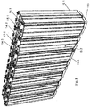
- Figure 11 shows four battery modules 400 that have been joined at each other by joining means 170 (not shown) inserted into the seats 117 in the base plates 110 of the respective battery modules.
- the base plate 111 may further comprise openings 122 arranged in the long sides of the circumferential flange 120 for joining the battery module 200 to joining flanges of the cover plate of an identical battery module.
- Figure 12 shows a first battery modules 400 that has placed on top of a second battery module 400. The joining flanges 141 of the second battery module 400 has been attached to the base plate 110 of the first battery module 400 by screws.
- FIG 8 shows a row of seven battery units 10 supported on the base plate. It may be noted that the battery units 10 are arranged alternatingly with regards to the terminals. That is, adjacent battery units 10 are positioned such that a positive terminal 14 of one battery unit 10 is adjacent (i.e. next to) a negative terminal 15 of an adjacent battery unit 10.
- Figure 9 shows the cover plate 130.
- the cover plate 130 is rectangular and has a width W that is substantially equal to the width w of the top surface 13 of a battery unit 10.
- the length L of the cover plate 130 may be substantially equal to the combined length 1 of the top surfaces 13 of the battery units 10 included in the battery module. That is, substantially equal to the combined length 1 of the top surfaces 13 of at least two battery units 10. However, preferably the length L of the cover plate 130 is less than the combined length 1 of the top surfaces 13 of the battery units 10 included in the battery module and selected such that the outermost terminals 14, 15 of the outermost battery units 10 in a row of battery units 10 are exposed to the environment. That is, not covered by the cover plate 130.
- the cover plate 130 further comprises a circumferential edge 138 which supports the cover plate onto the top surface 13 of the battery units 10.
- the cover plate 130 further comprises at least a first and a second connection means seat 139 for receiving a second flange 163 of the connection means 160 (see figure 2 ).
- Each of the seats 139 comprises a portion of the lower surface of the cover plate (not shown) onto which the second flange 163 is supported.
- the seat 139 further comprises an opening 140 in the circumferential edge 138 of the cover plate through which the second flange 163 of the connection means 160 is insertable.
- the second flange 163 may be attached in the seat 139 by screwing means or by press-fitting.
- the cover plate 130 may further comprise first and second joining flanges 141 that extend perpendicular from the long sides of the cover plate 130.
- the joining flanges 141 comprises openings 142 for connecting the battery module 200 with the base plate of an identical second battery module 200 that is placed on top of the present battery module (see figure 12 )
- the cover plate 130 further comprises electrical contact means 135 that are configured to electrically connect the battery units 10 of the battery module in series. That is, configured to electrically connect at least a first and a second battery unit 10.1, 10.2 in series.
- the cover plate 130 thereby comprises at least one pair of through openings 133, 134 that are arranged next to each other in longitudinal direction of the cover plate.
- the openings 133, 134 are arranged in a row in longitudinal direction of the cover plate.
- the openings 133, 134 are arranged to receive adjacent terminals 14, 15 of two adjacent battery units 10.
- a first pair of openings 133, 134 are configured to receive terminals 15.1 and 14.2 of battery units 10.1, 10.2.
- a second pair of openings 133, 134 in the cover plate are configured to receive terminals 15.2 and 14.3 of the battery units 10. 2, 10. 3and so on.
- the electrical contact means 135 may comprise electrically conductive sheet material 136 that is arranged around the openings 133, 134 of each pair of openings and that extends between the openings 133, 134 of each pair openings.
- the electrically conductive sheet material 136 is for example a cupper sheet that is arranged on the lower surface 132 of the cover plate 130. (schematically shown with dashed lines in figure 9 ).
- the electrically conductive sheet material 136 thus form a planar contact surface 137 around, i.e. concentrically with, each opening 133, 134.
- FIG. 10 shows schematically the assembly of the cover plate onto the top 12 of the respective battery units 10.
- terminals 14, 15 of two adjacent the battery units 10 extends into the openings 133, 134 of the cover plate 124.
- the contact surface 137 of the electrically conductive sheet material 136 rests onto the contact surface 17 of the terminals 14, 15.
- a fastening means 150 in the form of a bolt with a threaded shaft 152 and a head 151 is screwed into the threaded bore 16 of each terminal 14, 15 until the head 151 is in engaging contact with the upper side of the contact surface 137 of the electrically conductive sheet material 136.
- the lower side of the electrically conductive sheet material 136 is thus clamped against the contact surfaces 17 of the adjacent terminals 14, 15. This ensures that good electrical series connection is achieved between the terminals of adjacent battery units. It also ensures that parallel movement between the cover plate 130 and the top 12 of the respective battery units 10 is prevented.
Landscapes
- Chemical & Material Sciences (AREA)
- Chemical Kinetics & Catalysis (AREA)
- Electrochemistry (AREA)
- General Chemical & Material Sciences (AREA)
- Engineering & Computer Science (AREA)
- Aviation & Aerospace Engineering (AREA)
- Mechanical Engineering (AREA)
- Transportation (AREA)
- Power Engineering (AREA)
- Sustainable Development (AREA)
- Sustainable Energy (AREA)
- Life Sciences & Earth Sciences (AREA)
- Manufacturing & Machinery (AREA)
- Materials Engineering (AREA)
- Battery Mounting, Suspending (AREA)
Abstract
- a base plate (110) configured to support a respective bottom surface (19) of at least a first and a second battery unit (10.1, 10.2) and comprising engagement means (113) configured to fixate the position of the at least first and second battery unit (10.1, 10.2) onto the base plate (110), and;
- a cover plate (130) configured to be arranged on a respective top (12) of the at least first and second battery unit (10.1, 10.2) and comprising an electrical contact means (135) configured to electrically connect the at least first and the second battery unit (10.1, 10.2) in series, and;
- at least a first and a second connection means (160) for interlocking the base plate (110) and the cover plate (130).
Description
- The present disclosure relates to an arrangement for assembling rechargeable battery units into a battery module. The present disclosure also relates to a battery module comprising at least two battery units and an arrangement for assembling said rechargeable battery units into a battery module.
- Rechargeable Li-ion batteries are becoming an increasingly used electrical source for propelling lift-trucks due to their relatively short recharging time. The rechargeable Li-ion batteries are typically provided in the form of small individual cylinders that are stacked in a container and form a battery unit. The maximum voltage of each battery unit is limited and therefore it is necessary to electrically connect several battery units to each other in order to achieve a working voltage suitable for the lift truck. Typically, lift-trucks run on a working voltage of 24 V or 48V.
- Attempts have been made to collect battery units into larger modules. For example
US20170170438 shows a battery module in the form of a box in which several individual battery units are placed. Each battery unit has a vertical flange with openings that makes it possible to bolt the battery units to partition walls in the box. Separate and not further disclosed electrical connection are provided to electrically interconnect the battery units. The arrangement disclosed inUS20170170438 is marred with drawbacks. For example, the process of gather battery units in a box and subsequently bolt the battery units to the partition walls of the box and then electrically interconnect the battery units is cumbersome and work intensive. Also, since the battery units are collected in a box the maximum voltage as well as the geometrical design of the battery module is limited to specific applications. - Thus, it is an object of the present disclosure to provide an improved arrangement for assembling rechargeable battery units into a battery module that solves or at least mitigates at least one of the problems discussed above. In detail, it is an object of the present disclosure to provide an arrangement for assembling rechargeable battery units into a battery module that allows for easy assembly of the battery units in few working operations. It is a further object of the present disclosure to provide an arrangement for assembling rechargeable battery units into a battery module that allows for flexible design of battery modules.
- It is also an object of the present disclosure to provide a simple and robust battery module that may be assembled in few working operations.
- According to the present disclosure, at least one of these objects is achieved by an
arrangement 100 for assemblingrechargeable battery units 10 into abattery module 200 for a lift-truck, saidbattery units 10 having, respectively, ahousing 11 with abottom 18 and anopposing top 12 with a positive and anegative battery terminal arrangement 100 comprising; - a
base plate 110 configured to support arespective bottom surface 19 of at least a first and a second battery unit 10.1, 10.2 and comprising engagement means 113 configured to fixate the position of the at least first and second battery unit 10.1, 10.2 onto thebase plate 110, characterized in; - a
cover plate 130 configured to be arranged on arespective top 12 of the at least first and second battery unit 10.1, 10.2 and comprising an electrical contact means 135 configured to electrically connect the at least first and the second battery unit 10.1, 10.2 in series, and; - at least a first and a second connection means 160 for interlocking the
base plate 110 and thecover plate 130. - The arrangement for assembling
rechargeable battery units 10 according to the present disclosure provides a simple solution for assembling a plurality of pre-manufactured rechargeable battery units into a battery module . The claimed arrangement is very suitable for manual assembly of battery modules since it only requires a minimum of working steps to assemble the battery unit. In practice, the person assembling the battery modules needs only to place the battery units onto the base plate, apply the cover plate on top of the respective battery units and subsequently interlock the base plate and the cover plate with the connection means. Electrical series connection of the battery units is achieved when the cover plate is applied onto the tops of the battery units. - Preferably, the
base plate 110, and possibly also thecover plate 130, is rectangular and has a width (W) and a length (L), whereby the width (W) of the base plate (100 is substantially equal to or less than the width (w) of eachbattery unit 10. This is a favorable way of designing the claimed arrangement for providing a standard battery module which consist of a single row of battery units. Several battery modules may then be put together into larger aggregates to fit the power need of different truck types. - Preferably, the engagement means 113 comprises protrusions extending from the
base plate 110 and configured to be received incorresponding recesses 20 provided in abottom surface 19 of eachbattery unit 10. This provides a simple, yet effective way of fixating the battery units on to the upper surface of the base plate in order to prevent parallel movement between the base plate and the battery units. A person assembling the module may easily mount the battery unit on the base plate such that the protrusions of the base plate are received in the recesses in the bottom surface of the battery units. - Preferably, the
protrusions 113 are arranged in a first and a second parallel row along the length (L) of thebase plate 110. It is thereby advantageous that thebottom surface 19 of eachbattery unit 10 comprises at least a first andsecond recess 20 and that the number ofprotrusions 113 on thebase plate 110 correspond to the total number ofrecesses 20 of thebattery units 10. This makes it easy for a person to place the battery units in correct position on the base plate and the battery units are simultaneously prevented from rotating on the base plate by the provision of two recesses in each bottom surface. - Preferably, the arrangement for assembling battery units comprises a first and a second fastening means 150, 150 for attaching the
cover plate 110 to therespective top 12 of eachbattery unit 10. The arrangement for assembling battery units will thereby be completely locked to all the battery units. As a consequence thereof any movement between the separate battery units and the components of the arrangement for assembling battery units is completely eliminated in all directions. - Advantageously, the
cover plate 130 comprises afirst opening 133 for receiving aterminal second opening 134 for receiving aterminal conductive sheet material 136 arranged around the respective first and thesecond opening second opening conductive sheet material 136 of the first and thesecond opening cover plate 130 to therespective terminal - In addition, the
terminals battery unit 10 comprises athreaded bore 16 and acontact surface 17 and the fastening means 150 comprises ahead 151 and a corresponding threadedportion 152 configured to be received in the threadedbore 16 of aterminal battery unit 10, such that thehead 151 of the fastening means 150 is clamped against one side of the electricallyconductive sheet material 136 of anopening contact surface 17 of theterminal conductive sheet material 136 of said opening 133, 134. The result thereof is a very strong attachment of the cover plate to the respective tops of the battery units and a secure electrical series connection of the battery units. - In the arrangement for assembling battery units, the first and the
second connection element central portion 161 and afirst end flange 162 and asecond end flange 163 and thebase plate 110 and thecover plate 130 respectively comprises opposing first andsecond side edges 114; thebase plate 110 and thecover plate 130 may thereby comprise, respectively, at least afirst seat second seat respective opening opposing side edges 114 of thebase plate 110 and thecover plate 130. Preferably, a respectivefirst end flange 162 of the connection means 160 is configured to be attachable received in aseat 115 of thebase plate 110 through the opening 116 of saidseat 115 and a respectivesecond end flange 163 of the connection means 160 is configured to be attachable received in aseat 139 of thecover plate 130 through the opening 14 of saidseat 139. The advantage thereof is that the end flanges are easy to insert into the seats and that, in use, the end flanges are protected by the seats. - The
arrangement 100 for assembling battery units may also comprise ajoining means 170 for joining thearrangement 100 for assembling battery units to another, identical,arrangement 100 for assemblingrechargeable battery units 100. This allows for easy build-up of larger battery aggregates for lift-trucks that requires large supplies of electric power. - The present disclosure also relates to a
battery module 200 for a lift-truck comprising at least a first and a secondrechargeable battery unit 10,1, 10.2 having ahousing 11 with abottom 18 and anopposing top 12 with a positive and anegative battery terminal arrangement 100 for assembling the at least first and second rechargeable battery units 10.1, 10. 2 into abattery module 200 said arrangement (100) comprises; - a base plate (110) supporting a respective bottom surface (19) of said at least first and second battery unit (10.1, 10.2) and comprising engagement means (113) arranged to fixate the position of said at least first and second battery unit (10.1, 10.2) onto the base plate (110) and;
- a cover plate (130) arranged on a respective top (12) of the at least first and second battery unit (10.1, 10.2) and comprising an electrical contact means (135) arranged such that the at least first and the second battery unit (10.1, 10.2) are electrically connected in series, and;
- at least a first and a second connection means (160) arranged to interlock the base plate (110) and the cover plate (130).
-
-
Figure 1 : A schematic drawing of an arrangement for assembling battery units and a battery module according to the present disclosure. -
Figure 2 : A schematic drawing of a connection means of the arrangement for assembling battery units according to the present disclosure. -
Figure 3 : A schematic drawing of a joining means of the arrangement for assembling battery units according to the present disclosure. -
Figure 4, 5 : Schematic drawings of a rechargeable battery unit. -
Figure 6, 7 : Schematic drawings of a base plate of the arrangement for assembling battery units of the present disclosure. -
Figure 8 : A schematic drawing of a base plate of the arrangement for assembling battery units of the present disclosure and battery units. -
Figure 9 : A schematic drawing of a cover plate of the arrangement for assembling battery units of the present disclosure. -
Figure 10 : A schematic drawing of a portion of a cover plate of the arrangement for assembling battery units of the present disclosure. -
Figures 11 ,12 : Schematic drawings of aggregates of battery modules according to the present disclosure. - The arrangement for assembling rechargeable battery units into a battery module for a lift-truck according to the present disclosure will now be described more fully hereinafter. The arrangement for assembling rechargeable battery units into a battery module for a lift-truck according to the present disclosure may however be embodied in many different forms and should not be construed as limited to the embodiment set forth herein. Rather, this embodiment is provided by way of example so that this disclosure will be thorough and complete, and will fully convey the scope of the present disclosure to those persons skilled in the art. Where appropriate, the arrangement for assembling rechargeable battery units into a battery module for a lift-truck may be referred to as "the arrangement". Moreover, although specific terms may be employed herein, they are used in a generic and descriptive sense only and not for purposes of limitation. Furthermore, as used herein, the terms "comprise/comprises" or "include/includes" do not exclude the presence of other elements. Finally, reference signs in the claims are provided merely as a clarifying example and should not be construed as limiting the scope of the claims in any way.
-
Figure 1 shows an exemplary embodiment of abattery module 200 comprising anarrangement 100 for assembling rechargeable battery units into a battery module for a lift-truck according to the present disclosure. In the disclosed embodiment, thebattery module 200 comprises sevenbattery units 10. However, thebattery module 200 may comprise at least twobattery units 10 or any suitable number of more than two battery units. In order not to obscure the drawings, only the first and the last battery unit have been indicated with reference signs 10.1, 10.2. Thearrangement 100 comprises abase plate 110 for supporting thebattery units 10 and acover plate 130 configured to be arranged on top of thebattery units 10 and connection means 160 that are arranged to interlock thecover plate 130 and thebase plate 110. By "interlock" is meant that one end of each connection means 160 is attached to thebase plate 110 and the other end of the connection means 160 is attached to thecover plate 130. In the disclosed embodiment two connection means 160 are provided on each longside of thearrangement 100. However, the arrangement may comprise at least two connection means 160, or more. Thearrangement 100 may further comprise a fastening means 150, such as threaded bolts, for attaching thecover plate 130 to the top of the battery units. Thearrangement 100 may further comprise one or more joining means, 170 for joining thebattery module 200 to another identical battery module (not shown). - The various components of the
battery module 200 and thearrangement 100 will in the following be described with reference tofigures 2 - 6 . -
Figure 2 shows a connection means 160 which comprises an elongatedcentral portion 161 and a first andsecond end flange central portion 161. The first andsecond end flanges respective opening 164 for receiving a screws or protrusion in order to attach the first andsecond end flanges base plate 110 and to thecover plate 130. The connection means 160 are narrow and elongated. Thus the width of the connection means 160 is less than the width or the length of thebottom surface 19 of abattery unit 10. The length of the connection means 160 greater than the height of a battery unit and selected such that thefirst end flange 162 may be attached to thebase plate 110 and thesecond end 163 may be attached to thecover plate 130. The connection means 160 is rigid an may be manufactured from metal, e.g. steel strip or hard plastic material. -
Figure 3 shows a joining means 170 which comprises a first andsecond locking body 171 arranged symmetrically on opposite sides of a bridgingpart 174. Each lockingbody 171 is connected to the bridging part by anextension portion 175 and comprises astem 172 that extends perpendicular from the lockingbody 171 and that comprises ashoulder 173 at its end. -
Figure 4 shows abattery unit 10 which is configured to be assembled, together with at least one further identical battery unit, by an arrangement according to the present disclosure into a battery module for a lift-truck. Thebattery unit 10 comprises anelongated housing 11 of rectangular cross-section that has a closed top 12 and a closed bottom 18 having a length 1 and a width w. The top 12 comprises a flattop surface 13 and a positive battery terminal 14 (anode) and a negative battery terminal 15 (cathode). The battery terminals are spaced apart and oriented next to each other along the center of the top surface. Thebattery terminals top surface 13 and comprises a central threaded bore 16 and anannular contact surface 17 arranged concentrically with the threaded bore 16. Thehousing 11 encloses rechargeable Lithium-ion batteries (not shown) that are electrically connected to theterminals battery unit 10. -
Figure 5 shows the bottom 18 of thebattery unit 10 offigure 2 . The bottom 18 comprises aflat bottom surface 19 that is provided with engagement means in form ofrecesses 20. In the embodiment shown infigure 5 , fourrecesses 20 are provided, spaced apart from each other, and oriented adjacent the corners of therectangular bottom surface 19. However, the number ofrecesses 20 may be fewer than four, e.g. at least tworecesses 20 may be provided in the bottom surface of thebattery unit 10. -
Figure 6 , shows thebase plate 110 of thearrangement 100. Thebase plate 110 may be elongate and rectangular. The width W of thebase plate 110 is substantially equal to the width w ofbottom surface 19 of the battery unit 10 (seefigure 4 ). The length L of thebase plate 110 is substantially equal the combined length 1 of the bottom surfaces of thebattery units 10 included in the battery module. Thus, the length L of thebase plate 110 may be substantially equal the combined length 1 of thebottom surface 19 of at least twobattery units 10. - The
base plate 110 has anupper surface 111 that is configured to support the bottom surfaces of 19 of at least twobattery units 10. That is, at least twobattery units 10 may be placed onto theupper surface 111 of thebase plate 110. Theupper surface 111 of thebase plate 110 comprises engagement means 113 that are configured to fixate the position of the at least twobattery units 10 onto thebase plate 110. As shown infigure 4 , the engagement means 113 of thebase plate 110 may be protrusions that extend axially from theupper surface 111 of thebase plate 110. Theprotrusions 113 are configured to be received in the correspondingrecesses 20 in thebottom surface 19 of thebattery units 10. That is, the engagement means 113 on the upper surface of thebase plate 110 are configured to engage with the corresponding engagement means in form of recesses in thebottom surface 19 of the at least twobattery units 10. By "fixating" is meant that thebattery units 10 are prevented from moving parallel with, i.e. slide on, theupper surface 111 of thebase plate 110. Theprotrusions 113 are distributed over of theupper surface 111 of thebase plate 110 such that thebattery units 10 may be placed adjacent each other in a row on the base plate. Infigure 4 , theprotrusions 113 are arranged in two parallel rows along the length L of the base plate. - The
base plate 110 further comprises acircumferential edge 114. - The
base plate 110 further comprises at least a first and a second connection meansseat 115, for receiving a respectivefirst end flange 162 of the connection means 160. Turning tofigure 7 , eachseat 115 comprises a portion of thelower surface 112 of thebase plate 110 onto which thefirst end flange 162 of the connection means 160 is supported. In use, this portion of thelower surface 112 of thebase plate 110 supports thefirst end flange 162 of the connection means 160. Theseat 115 further comprises anopening 116 in thecircumferential edge 114 of thebase plate 110 through which thefirst end flange 162 of the connection means 160 is insertable (seefigure 6 ). Thefirst end flange 162 may be attached in theseat 115 by a protrusion 115.1 in thelower surface 112 of thebase plate 111. However, theend flange 162 may also be attached in the seat by a screwing means or by press-fitting. - The
base plate 110 further comprises a firstlocking body seat 117 for receiving a lockingbody 171 of a joining means 170 for joining thebattery module 200 to another identical battery module. Turning tofigure 7 , Theseat 117 comprises a portion of thelower surface 112 of thebase plate 110 which is configured to receiving the lockingbody 171. Theseat 117 may thereby comprises a limitingwall 118 which encloses the area of theseat 117. Theseat 117 further comprises arecess 119 in theupper surface 111 of thebase plate 110 forming an abutment surface for theshoulder 173 of the lockingbody 171. Theseat 117 further comprises a throughopening 120 in thebase plate 110 through which thestem 172 of the lockingbody 171 may extend. Theseat 117 further comprises anopening 121 in thecircumferential edge 114 of thebase plate 110 through which theextension portion 175 of the joining means may extend. -
Figure 11 shows fourbattery modules 400 that have been joined at each other by joining means 170 (not shown) inserted into theseats 117 in thebase plates 110 of the respective battery modules. - Returning to
figure 6 . Thebase plate 111 may further compriseopenings 122 arranged in the long sides of thecircumferential flange 120 for joining thebattery module 200 to joining flanges of the cover plate of an identical battery module.Figure 12 shows afirst battery modules 400 that has placed on top of asecond battery module 400. The joiningflanges 141 of thesecond battery module 400 has been attached to thebase plate 110 of thefirst battery module 400 by screws. -
Figure 8 , shows a row of sevenbattery units 10 supported on the base plate. It may be noted that thebattery units 10 are arranged alternatingly with regards to the terminals. That is,adjacent battery units 10 are positioned such that apositive terminal 14 of onebattery unit 10 is adjacent (i.e. next to) anegative terminal 15 of anadjacent battery unit 10. -
Figure 9 shows thecover plate 130. Thecover plate 130 is rectangular and has a width W that is substantially equal to the width w of thetop surface 13 of abattery unit 10. The length L of thecover plate 130 may be substantially equal to the combined length 1 of thetop surfaces 13 of thebattery units 10 included in the battery module. That is, substantially equal to the combined length 1 of thetop surfaces 13 of at least twobattery units 10. However, preferably the length L of thecover plate 130 is less than the combined length 1 of thetop surfaces 13 of thebattery units 10 included in the battery module and selected such that theoutermost terminals outermost battery units 10 in a row ofbattery units 10 are exposed to the environment. That is, not covered by thecover plate 130. Thecover plate 130 further comprises acircumferential edge 138 which supports the cover plate onto thetop surface 13 of thebattery units 10. - The
cover plate 130 further comprises at least a first and a second connection meansseat 139 for receiving asecond flange 163 of the connection means 160 (seefigure 2 ). Each of theseats 139 comprises a portion of the lower surface of the cover plate (not shown) onto which thesecond flange 163 is supported. Theseat 139 further comprises anopening 140 in thecircumferential edge 138 of the cover plate through which thesecond flange 163 of the connection means 160 is insertable. Thesecond flange 163 may be attached in theseat 139 by screwing means or by press-fitting. - The
cover plate 130 may further comprise first and second joiningflanges 141 that extend perpendicular from the long sides of thecover plate 130. The joiningflanges 141 comprisesopenings 142 for connecting thebattery module 200 with the base plate of an identicalsecond battery module 200 that is placed on top of the present battery module (seefigure 12 ) - The
cover plate 130 further comprises electrical contact means 135 that are configured to electrically connect thebattery units 10 of the battery module in series. That is, configured to electrically connect at least a first and a second battery unit 10.1, 10.2 in series. - The
cover plate 130 thereby comprises at least one pair of throughopenings openings - The
openings adjacent terminals adjacent battery units 10. Thus, with regards to the row ofbattery units 10 offigure 8 , a first pair ofopenings openings battery units 10. 2, 10. 3and so on. - The electrical contact means 135 may comprise electrically
conductive sheet material 136 that is arranged around theopenings openings conductive sheet material 136 is for example a cupper sheet that is arranged on the lower surface 132 of thecover plate 130. (schematically shown with dashed lines infigure 9 ). The electricallyconductive sheet material 136 thus form aplanar contact surface 137 around, i.e. concentrically with, eachopening -
Figure 10 shows schematically the assembly of the cover plate onto the top 12 of therespective battery units 10. Thus,terminals battery units 10 extends into theopenings contact surface 137 of the electricallyconductive sheet material 136 rests onto thecontact surface 17 of theterminals shaft 152 and ahead 151 is screwed into the threaded bore 16 of each terminal 14, 15 until thehead 151 is in engaging contact with the upper side of thecontact surface 137 of the electricallyconductive sheet material 136. The lower side of the electricallyconductive sheet material 136 is thus clamped against the contact surfaces 17 of theadjacent terminals cover plate 130 and the top 12 of therespective battery units 10 is prevented.
Claims (13)
- An arrangement (100) for assembling rechargeable battery units (10) into a battery module (200) for a lift-truck, said battery units (10) having, respectively, a housing (11) with a bottom (18) and an opposing top (12) with a positive and a negative battery terminal (14, 15), said arrangement (100) comprising;- a base plate (110) configured to support a respective bottom surface (19) of at least a first and a second battery unit (10.1, 10.2) and comprising engagement means (113) configured to fixate the position of the at least first and second battery unit (10.1, 10.2) onto the base plate (110), characterized in;- a cover plate (130) configured to be arranged on a respective top (12) of the at least first and second battery unit (10.1, 10.2) and comprising an electrical contact means (135) configured to electrically connect the at least first and the second battery unit (10.1, 10.2) in series, and;- at least a first and a second connection means (160) for interlocking the base plate (110) and the cover plate (130).
- The arrangement (100) according to claim 1, wherein the base plate (110) is rectangular and has a width (W) and a length (L), whereby the width (W) of the base plate (110) is substantially equal to, or less than, the width (w) of each battery unit (10).
- The arrangement (100) according to claim 1 or 2, wherein the engagement means (113) comprises protrusions (113) extending from the base plate (110) and configured to be received in corresponding recesses (20) in a bottom surface (19) of each battery unit (10).
- The arrangement (100) according to claim 3, wherein the protrusions (113) are arranged in a first and a second parallel row along the length (L) of the base plate (110).
- The arrangement (100) according to claim 3 or 4, wherein the bottom surface (19) of each battery unit (10) comprises at least a first and second recess (20) and wherein the number of protrusions (113) on the base plate (110) correspond to the total number of recesses (20) of the battery units (10).
- The arrangement (100) according to anyone of claims 1 - 5, wherein the cover plate (130) is rectangular and has a width (W) and a length (L) whereby the width (W) of the cover plate (130) is substantially equal to the width (w) of each battery unit (10).
- The arrangement (100) according to anyone of claim 1 - 6, comprising a first and a second fastening means (150, 150) for attaching the cover plate (130) to the respective top (12) of each battery unit (10).
- The arrangement (100) according to anyone of claims 1 - 7, wherein the cover plate (130) comprises a first opening (133) for receiving a terminal (14, 15) of a first battery unit (10.1) and a second opening (134) for an receiving a terminal (14, 15) of a second battery unit (10.2), wherein the electrical contact means (135) comprises electrically conductive sheet material (136) arranged around the respective first and the second opening (133, 134) and extending between the first and the second opening (133, 134).
- The arrangement (100) according to claim 7 and 8, wherein the first and the second fastening means (150, 150) are configured to clamp the electrically conductive sheet material (136) of the first and the second opening (133, 134) of the cover plate (130) to the respective terminal (14,15) of the first and second battery unit (10.1, 10.2).
- The arrangement (100) according to claim 9, wherein the terminals (14, 15) of each battery unit (10) comprises a threaded bore (16) and a contact surface (17) and wherein the fastening means (150) comprises a head (151) and a corresponding threaded portion (152) configured to be received in the threaded bore (16) of a terminal (14, 15) of a battery unit (10), such that the head (151) of the fastening means (150) is clamped against one side of the electrically conductive sheet material (136) of an opening (133, 134) and the contact surface (17) of the terminal (14,15) is clamped against the other side of the electrically conductive sheet material (136) of said opening (133, 134).
- The arrangement (100) according to anyone of claims 1 - 10, wherein the first and the second connection means (160, 160), respectively comprises an elongated central portion (161) and a first end flange (162) and a second end flange (163), wherein;- the base plate (110) comprises opposing first and second side edges (114) and the cover plate (130) comprises opposing first and second side edges (138), wherein;- the base plate (110) comprises at least a first and a second seat (115, 115) having a respective opening (116,116) in a respective one of the opposing side edges (114) of the base plate (110) and the cover plate (130) comprises at least a first and a second seat (139, 139) having a respective opening (140, 140) in a respective one of the opposing side edges (138, 138) of the cover plate (130), wherein;- a respective first end flange (162) of the first and the second connection means (160) is configured to be attachable received in a respective seat (115) of the base plate (110) through the opening (116) and a respective second end flange (163) of the first and the second connection means (160) is configured to be attachable received in a respective seat (139) of the cover plate (130) through the opening (140).
- The arrangement (100) according to anyone of claims 1 - 11, comprising a joining means (170) for joining the arrangement (100) to a another, identical, arrangement (100) for assembling rechargeable battery units (10).
- A battery module (200) for a lift-truck comprising at least a first and a second rechargeable battery unit (10,1, 10.2) having a housing (11) with a bottom (18) and an opposing top (12) with a positive and a negative battery terminal (14, 15) and an arrangement (100) for assembling the at least first and second rechargeable battery units (10.1, 10.2) into a battery module (200) according to anyone of claims 1 - 12.
Applications Claiming Priority (1)
| Application Number | Priority Date | Filing Date | Title |
|---|---|---|---|
| SE1850177A SE541672C2 (en) | 2018-02-16 | 2018-02-16 | An arrangement for assembling rechargeable battery units into a battery module and a battery module |
Publications (1)
| Publication Number | Publication Date |
|---|---|
| EP3528309A1 true EP3528309A1 (en) | 2019-08-21 |
Family
ID=63792068
Family Applications (1)
| Application Number | Title | Priority Date | Filing Date |
|---|---|---|---|
| EP19155067.2A Pending EP3528309A1 (en) | 2018-02-16 | 2019-02-01 | An arrangement for assembling rechargeable battery units into a battery module and a battery module |
Country Status (4)
| Country | Link |
|---|---|
| US (1) | US11302980B2 (en) |
| EP (1) | EP3528309A1 (en) |
| CN (1) | CN110165101A (en) |
| SE (1) | SE541672C2 (en) |
Families Citing this family (1)
| Publication number | Priority date | Publication date | Assignee | Title |
|---|---|---|---|---|
| US12002975B2 (en) * | 2020-12-01 | 2024-06-04 | Caterpillar Inc. | Structural battery module and battery pack |
Citations (2)
| Publication number | Priority date | Publication date | Assignee | Title |
|---|---|---|---|---|
| EP2219245A1 (en) * | 2009-02-17 | 2010-08-18 | Samsung SDI Co., Ltd. | Secondary Battery with Protection Circuit Module |
| CN206893667U (en) * | 2017-06-20 | 2018-01-16 | 江苏银基烯碳能源科技有限公司 | Rectangular cell module |
Family Cites Families (27)
| Publication number | Priority date | Publication date | Assignee | Title |
|---|---|---|---|---|
| DE10003247B4 (en) * | 1999-01-29 | 2005-02-24 | Sanyo Electric Co., Ltd., Moriguchi | Power source, equipped with rechargeable batteries |
| EP1033771B1 (en) * | 1999-03-03 | 2017-07-26 | Panasonic Corporation | Integrated sealed secondary battery |
| JP4186413B2 (en) * | 2000-11-21 | 2008-11-26 | 新神戸電機株式会社 | Battery module |
| CN1856889B (en) * | 2003-10-14 | 2012-03-14 | 株式会社Lg化学 | Cartridge-type lithium ion polymer battery pack |
| CN2904309Y (en) * | 2006-03-10 | 2007-05-23 | 顺达科技股份有限公司 | Improved box structure |
| JP5288853B2 (en) * | 2008-03-24 | 2013-09-11 | 株式会社東芝 | Battery pack |
| JP5666274B2 (en) * | 2010-12-04 | 2015-02-12 | 三洋電機株式会社 | Battery pack and vehicle equipped with the same |
| JP5699576B2 (en) * | 2010-12-08 | 2015-04-15 | ソニー株式会社 | Laminated microporous membrane, battery separator and non-aqueous electrolyte battery |
| KR101264495B1 (en) * | 2011-03-10 | 2013-05-14 | 로베르트 보쉬 게엠베하 | Secondary Battery And Battery Pack having thereof |
| US8859130B2 (en) * | 2011-03-11 | 2014-10-14 | GM Global Technology Operations LLC | Battery cover for a high voltage automotive battery |
| WO2012133711A1 (en) * | 2011-03-31 | 2012-10-04 | 三洋電機株式会社 | Method for producing power source device, power source device, and vehicle provided with power source device |
| KR101252952B1 (en) * | 2011-05-02 | 2013-04-15 | 로베르트 보쉬 게엠베하 | Battery module for preventing movement of battery cell |
| EP2523246B1 (en) | 2011-05-11 | 2017-03-08 | C.R.F. Società Consortile per Azioni | Modular battery for electric or hybrid vehicles |
| US9472797B2 (en) * | 2011-05-25 | 2016-10-18 | Samsung Sdi Co., Ltd. | Battery pack |
| JP5803405B2 (en) * | 2011-08-10 | 2015-11-04 | 株式会社オートネットワーク技術研究所 | Bus bar cover and bus bar with cover |
| JP5807488B2 (en) | 2011-09-28 | 2015-11-10 | ソニー株式会社 | Battery holder, battery storage case, battery pack, power storage system, electronic device, and electric vehicle |
| US9362536B2 (en) | 2012-04-25 | 2016-06-07 | Robert Bosch Gmbh | Optimized module restraint system |
| KR101669114B1 (en) * | 2012-04-30 | 2016-10-25 | 삼성에스디아이 주식회사 | Battery pack having modulization structure |
| CN104781949B (en) * | 2012-08-27 | 2018-07-24 | Nec能源元器件株式会社 | Power storage device |
| US10790489B2 (en) * | 2012-10-11 | 2020-09-29 | Cadenza Innovation, Inc. | Lithium ion battery |
| JP6149550B2 (en) * | 2013-07-02 | 2017-06-21 | ソニー株式会社 | Power storage device, power storage system, electronic device, electric vehicle, and power system |
| KR101698768B1 (en) * | 2013-07-18 | 2017-01-23 | 삼성에스디아이 주식회사 | Battery pack |
| JP5925755B2 (en) * | 2013-12-20 | 2016-05-25 | プライムアースEvエナジー株式会社 | Battery module adjustment method and battery module adjustment apparatus |
| DE102015215502A1 (en) | 2015-08-13 | 2017-02-16 | Robert Bosch Gmbh | Housing for battery module as well as battery module, battery and vehicle |
| CN106169543A (en) | 2016-07-11 | 2016-11-30 | 深圳市统凌科技有限公司 | A kind of battery modules and electric motor car thereof |
| US10601016B2 (en) * | 2016-10-14 | 2020-03-24 | Tiveni Mergeco, Inc. | Center contact plate configured to establish electrical bonds to different groups of battery cells in a battery module |
| CN113690520A (en) * | 2016-11-16 | 2021-11-23 | 奥动新能源汽车科技有限公司 | Vehicle-mounted power battery box |
-
2018
- 2018-02-16 SE SE1850177A patent/SE541672C2/en unknown
-
2019
- 2019-02-01 EP EP19155067.2A patent/EP3528309A1/en active Pending
- 2019-02-14 US US16/276,610 patent/US11302980B2/en active Active
- 2019-02-15 CN CN201910116628.0A patent/CN110165101A/en active Pending
Patent Citations (2)
| Publication number | Priority date | Publication date | Assignee | Title |
|---|---|---|---|---|
| EP2219245A1 (en) * | 2009-02-17 | 2010-08-18 | Samsung SDI Co., Ltd. | Secondary Battery with Protection Circuit Module |
| CN206893667U (en) * | 2017-06-20 | 2018-01-16 | 江苏银基烯碳能源科技有限公司 | Rectangular cell module |
Also Published As
| Publication number | Publication date |
|---|---|
| SE541672C2 (en) | 2019-11-26 |
| US20190259993A1 (en) | 2019-08-22 |
| US11302980B2 (en) | 2022-04-12 |
| SE1850177A1 (en) | 2018-09-20 |
| CN110165101A (en) | 2019-08-23 |
Similar Documents
| Publication | Publication Date | Title |
|---|---|---|
| US9564661B2 (en) | Battery module and wiring module | |
| US7871723B2 (en) | Power source device | |
| US9350088B2 (en) | Swaging structure for metallic members and bus bar using the same | |
| US8110300B2 (en) | Battery mounting system | |
| RU2477548C2 (en) | Battery consisting of multiple cells installed and interconnected without application of welding | |
| US11247572B2 (en) | Removable battery component carrier, battery system including removable battery component carrier, and vehicle including battery system | |
| EP3220445B1 (en) | Battery pack | |
| CN107180931B (en) | Battery pack | |
| CN112496479B (en) | Electrolytic polishing device | |
| US20160359153A1 (en) | Electric storage device | |
| KR102622140B1 (en) | Battery assembly module | |
| JP2016018766A (en) | Power storage module | |
| US20120219846A1 (en) | Battery cell support and assembly thereof | |
| CN109792014A (en) | Energy-storage module and assemble method | |
| DE102015104620A1 (en) | Support structure for battery cells within a traction battery assembly | |
| CN109792026B (en) | Connection module | |
| US20120114996A1 (en) | Battery holder, battery array using same | |
| EP3223339B1 (en) | Battery compression inhibitor and battery module comprising same | |
| US9397328B2 (en) | Flexible busbar holder for welded cells | |
| US20170200927A1 (en) | Cell module | |
| EP3528309A1 (en) | An arrangement for assembling rechargeable battery units into a battery module and a battery module | |
| EP3930103B1 (en) | Connector, battery management unit, and battery pack | |
| US5942353A (en) | Battery with replaceable cells | |
| US10777781B2 (en) | Monoblocs and monobloc batteries | |
| EP4246736A1 (en) | Charging pile |
Legal Events
| Date | Code | Title | Description |
|---|---|---|---|
| PUAI | Public reference made under article 153(3) epc to a published international application that has entered the european phase |
Free format text: ORIGINAL CODE: 0009012 |
|
| STAA | Information on the status of an ep patent application or granted ep patent |
Free format text: STATUS: THE APPLICATION HAS BEEN PUBLISHED |
|
| AK | Designated contracting states |
Kind code of ref document: A1 Designated state(s): AL AT BE BG CH CY CZ DE DK EE ES FI FR GB GR HR HU IE IS IT LI LT LU LV MC MK MT NL NO PL PT RO RS SE SI SK SM TR |
|
| AX | Request for extension of the european patent |
Extension state: BA ME |
|
| STAA | Information on the status of an ep patent application or granted ep patent |
Free format text: STATUS: REQUEST FOR EXAMINATION WAS MADE |
|
| 17P | Request for examination filed |
Effective date: 20200219 |
|
| RBV | Designated contracting states (corrected) |
Designated state(s): AL AT BE BG CH CY CZ DE DK EE ES FI FR GB GR HR HU IE IS IT LI LT LU LV MC MK MT NL NO PL PT RO RS SE SI SK SM TR |
|
| STAA | Information on the status of an ep patent application or granted ep patent |
Free format text: STATUS: EXAMINATION IS IN PROGRESS |
|
| 17Q | First examination report despatched |
Effective date: 20230201 |
|
| P01 | Opt-out of the competence of the unified patent court (upc) registered |
Effective date: 20230523 |