EP3528258B1 - Verfahren und systeme zur bestimmung der verwendungskonformität einer kompressionstherapievorrichtung - Google Patents
Verfahren und systeme zur bestimmung der verwendungskonformität einer kompressionstherapievorrichtung Download PDFInfo
- Publication number
- EP3528258B1 EP3528258B1 EP19160890.0A EP19160890A EP3528258B1 EP 3528258 B1 EP3528258 B1 EP 3528258B1 EP 19160890 A EP19160890 A EP 19160890A EP 3528258 B1 EP3528258 B1 EP 3528258B1
- Authority
- EP
- European Patent Office
- Prior art keywords
- therapy
- data
- cell
- sleeve
- compression
- Prior art date
- Legal status (The legal status is an assumption and is not a legal conclusion. Google has not performed a legal analysis and makes no representation as to the accuracy of the status listed.)
- Active
Links
Images


Classifications
-
- G—PHYSICS
- G16—INFORMATION AND COMMUNICATION TECHNOLOGY [ICT] SPECIALLY ADAPTED FOR SPECIFIC APPLICATION FIELDS
- G16H—HEALTHCARE INFORMATICS, i.e. INFORMATION AND COMMUNICATION TECHNOLOGY [ICT] SPECIALLY ADAPTED FOR THE HANDLING OR PROCESSING OF MEDICAL OR HEALTHCARE DATA
- G16H40/00—ICT specially adapted for the management or administration of healthcare resources or facilities; ICT specially adapted for the management or operation of medical equipment or devices
- G16H40/60—ICT specially adapted for the management or administration of healthcare resources or facilities; ICT specially adapted for the management or operation of medical equipment or devices for the operation of medical equipment or devices
- G16H40/67—ICT specially adapted for the management or administration of healthcare resources or facilities; ICT specially adapted for the management or operation of medical equipment or devices for the operation of medical equipment or devices for remote operation
-
- G—PHYSICS
- G16—INFORMATION AND COMMUNICATION TECHNOLOGY [ICT] SPECIALLY ADAPTED FOR SPECIFIC APPLICATION FIELDS
- G16H—HEALTHCARE INFORMATICS, i.e. INFORMATION AND COMMUNICATION TECHNOLOGY [ICT] SPECIALLY ADAPTED FOR THE HANDLING OR PROCESSING OF MEDICAL OR HEALTHCARE DATA
- G16H20/00—ICT specially adapted for therapies or health-improving plans, e.g. for handling prescriptions, for steering therapy or for monitoring patient compliance
- G16H20/30—ICT specially adapted for therapies or health-improving plans, e.g. for handling prescriptions, for steering therapy or for monitoring patient compliance relating to physical therapies or activities, e.g. physiotherapy, acupressure or exercising
-
- A—HUMAN NECESSITIES
- A61—MEDICAL OR VETERINARY SCIENCE; HYGIENE
- A61H—PHYSICAL THERAPY APPARATUS, e.g. DEVICES FOR LOCATING OR STIMULATING REFLEX POINTS IN THE BODY; ARTIFICIAL RESPIRATION; MASSAGE; BATHING DEVICES FOR SPECIAL THERAPEUTIC OR HYGIENIC PURPOSES OR SPECIFIC PARTS OF THE BODY
- A61H9/00—Pneumatic or hydraulic massage
- A61H9/0007—Pulsating
-
- G—PHYSICS
- G16—INFORMATION AND COMMUNICATION TECHNOLOGY [ICT] SPECIALLY ADAPTED FOR SPECIFIC APPLICATION FIELDS
- G16H—HEALTHCARE INFORMATICS, i.e. INFORMATION AND COMMUNICATION TECHNOLOGY [ICT] SPECIALLY ADAPTED FOR THE HANDLING OR PROCESSING OF MEDICAL OR HEALTHCARE DATA
- G16H10/00—ICT specially adapted for the handling or processing of patient-related medical or healthcare data
- G16H10/60—ICT specially adapted for the handling or processing of patient-related medical or healthcare data for patient-specific data, e.g. for electronic patient records
-
- G—PHYSICS
- G16—INFORMATION AND COMMUNICATION TECHNOLOGY [ICT] SPECIALLY ADAPTED FOR SPECIFIC APPLICATION FIELDS
- G16H—HEALTHCARE INFORMATICS, i.e. INFORMATION AND COMMUNICATION TECHNOLOGY [ICT] SPECIALLY ADAPTED FOR THE HANDLING OR PROCESSING OF MEDICAL OR HEALTHCARE DATA
- G16H40/00—ICT specially adapted for the management or administration of healthcare resources or facilities; ICT specially adapted for the management or operation of medical equipment or devices
- G16H40/60—ICT specially adapted for the management or administration of healthcare resources or facilities; ICT specially adapted for the management or operation of medical equipment or devices for the operation of medical equipment or devices
- G16H40/63—ICT specially adapted for the management or administration of healthcare resources or facilities; ICT specially adapted for the management or operation of medical equipment or devices for the operation of medical equipment or devices for local operation
-
- A—HUMAN NECESSITIES
- A61—MEDICAL OR VETERINARY SCIENCE; HYGIENE
- A61H—PHYSICAL THERAPY APPARATUS, e.g. DEVICES FOR LOCATING OR STIMULATING REFLEX POINTS IN THE BODY; ARTIFICIAL RESPIRATION; MASSAGE; BATHING DEVICES FOR SPECIAL THERAPEUTIC OR HYGIENIC PURPOSES OR SPECIFIC PARTS OF THE BODY
- A61H2201/00—Characteristics of apparatus not provided for in the preceding codes
- A61H2201/50—Control means thereof
- A61H2201/5002—Means for controlling a set of similar massage devices acting in sequence at different locations on a patient
-
- A—HUMAN NECESSITIES
- A61—MEDICAL OR VETERINARY SCIENCE; HYGIENE
- A61H—PHYSICAL THERAPY APPARATUS, e.g. DEVICES FOR LOCATING OR STIMULATING REFLEX POINTS IN THE BODY; ARTIFICIAL RESPIRATION; MASSAGE; BATHING DEVICES FOR SPECIAL THERAPEUTIC OR HYGIENIC PURPOSES OR SPECIFIC PARTS OF THE BODY
- A61H2201/00—Characteristics of apparatus not provided for in the preceding codes
- A61H2201/50—Control means thereof
- A61H2201/5007—Control means thereof computer controlled
- A61H2201/501—Control means thereof computer controlled connected to external computer devices or networks
- A61H2201/5012—Control means thereof computer controlled connected to external computer devices or networks using the internet
-
- A—HUMAN NECESSITIES
- A61—MEDICAL OR VETERINARY SCIENCE; HYGIENE
- A61H—PHYSICAL THERAPY APPARATUS, e.g. DEVICES FOR LOCATING OR STIMULATING REFLEX POINTS IN THE BODY; ARTIFICIAL RESPIRATION; MASSAGE; BATHING DEVICES FOR SPECIAL THERAPEUTIC OR HYGIENIC PURPOSES OR SPECIFIC PARTS OF THE BODY
- A61H2201/00—Characteristics of apparatus not provided for in the preceding codes
- A61H2201/50—Control means thereof
- A61H2201/5058—Sensors or detectors
- A61H2201/5071—Pressure sensors
-
- A—HUMAN NECESSITIES
- A61—MEDICAL OR VETERINARY SCIENCE; HYGIENE
- A61H—PHYSICAL THERAPY APPARATUS, e.g. DEVICES FOR LOCATING OR STIMULATING REFLEX POINTS IN THE BODY; ARTIFICIAL RESPIRATION; MASSAGE; BATHING DEVICES FOR SPECIAL THERAPEUTIC OR HYGIENIC PURPOSES OR SPECIFIC PARTS OF THE BODY
- A61H2201/00—Characteristics of apparatus not provided for in the preceding codes
- A61H2201/50—Control means thereof
- A61H2201/5097—Control means thereof wireless
-
- A—HUMAN NECESSITIES
- A61—MEDICAL OR VETERINARY SCIENCE; HYGIENE
- A61H—PHYSICAL THERAPY APPARATUS, e.g. DEVICES FOR LOCATING OR STIMULATING REFLEX POINTS IN THE BODY; ARTIFICIAL RESPIRATION; MASSAGE; BATHING DEVICES FOR SPECIAL THERAPEUTIC OR HYGIENIC PURPOSES OR SPECIFIC PARTS OF THE BODY
- A61H9/00—Pneumatic or hydraulic massage
- A61H9/005—Pneumatic massage
- A61H9/0078—Pneumatic massage with intermittent or alternately inflated bladders or cuffs
Definitions
- Venous insufficiency can result when the superficial veins of an extremity empty into the deep veins of the lower leg.
- the contractions of the calf muscles act as a pump, moving blood into the popliteal vein, the outflow vessel. Failure of this pumping action can occur as a result of muscle weakness, overall chamber size reduction, valvular incompetence, and/or outflow obstruction.
- Each of these conditions can lead to venous stasis and hypertension in the affected area.
- Lymphedema which is swelling due to a blockage of the lymph passages, may be caused by lymphatic obstruction, a blockage of the lymph vessels that drain fluid from tissues throughout the body. This is most commonly due to cancer surgery, general surgery, tumors, radiation treatments, trauma and congenital anomalies. Lymphedema is a chronic condition that currently has no cure.
- Fluid accumulation can be painful and debilitating if not treated. Fluid accumulation can reduce oxygen transport, interfere with wound healing, provide a medium that support infections, or even result in the loss of a limb if left untreated.
- Compression therapy devices are often used in the treatment of venous insufficiency by moving the accumulated bodily fluids. Additional conditions may also benefit from the use of compression therapy devices.
- Such devices typically include an air compressor that may blow air through tubes to an appliance such as a sleeve or boot containing a number of separately inflatable cells that is fitted over a problem area (such as an extremity or torso).
- Such devices may also include pneumatic components adapted to inflate and exhaust the cells, and control circuitry governing the pneumatic components.
- a therapeutic cycle or protocol may involve, for example, sequential inflation of the cells to a pre-set pressure in a distal to a proximal order, followed by exhausting all the cells in concert.
- Multiple compression therapy sessions may be required to help maintain proper fluid flow in the patient over time. While such therapy sessions may be provided under supervision by a therapist or physician at a clinic or hospital, it may be more practical to have the patient self-administer the therapy at home using rented therapy equipment.
- Home therapy has the advantage of being more convenient for the patient, who may schedule the therapy sessions at will and who will not need to travel to a medical facility for the sessions. In addition, home therapy has the economic advantage of not requiring the time and resources of either medical personnel or facilities.
- a potential disadvantage of home therapy is a lack of patient compliance.
- a therapeutic session may be uncomfortable, and a patient may not feel motivated to take time from his or her schedule to perform the therapy.
- Patient compliance is important to several parties associated with the therapy.
- the manufacturer or supplier of the equipment may want to monitor patient use of the equipment as part of ongoing post-sales quality assurance,
- the physician and/or therapist may want to monitor compliance as part of their overall monitoring of patient health.
- a physician may be able to determine if a change in the therapeutic protocol may be required.
- health insurers may reimburse the companies providing the therapeutic device and/or disposable items associated with it.
- the insurers may reimburse for equipment rentals only if the equipment is actually in use.
- Other individuals and organizations may have an interest in patient compliance, including, as non-limiting examples, researchers, family members, clinical trial registries, and accountable care organizations (ACO). It is therefore important to assure patient compliance in using such a compression therapy device.
- ACO accountable care organizations
- Document US2007/049853 represents the closest prior art and discloses a compression therapy device to provide compression therapy to a patient and monitor therapy compliance by the patient, comprising a processor, an inflatable compression sleeve with cells and coupled thereto 3-way function valves configured to inflate cells, to exhaust to deflate the cells, and to close.
- a controller controls inflation and executes a compression therapy protocol, and has a sensor which measures performance variables of the operation of the cells to completion of the protocol.
- a metric of patient compliance is calculated by calculating a difference between operational therapy data and identified existing therapy data, and is transmitted to a compliance data recipient.
- valve is a reference to one or more valves and equivalents thereof known to those skilled in the art, and so forth.
- all technical and scientific terms used herein have the same meanings as commonly understood by one of ordinary skill in the art.
- the present invention discloses a compression therapy device as defined by claims 1-13.
- transmitting the metric of patient compliance may include activating, by the at least one patient, a user input interface device associated with the controller, receiving, by the at least one patient, the metric of patient compliance from a user output interface device associated with the controller, and communicating, by the at least one patient, the metric of patient compliance to the at least one compliance data recipient.
- transmitting the metric of patient compliance may include one or more of removing a removable data storage device from the controller and placing the removable data storage device in data communication with a computing device that is further in data communication with an electronic device controlled at least in part by the at least one compliance data recipient, transmitting the metric over an Ethernet connection to a computing device in data communication with a website controlled at least in part by the at least one compliance data recipient, transmitting the metric via an infrared connection device to a computing device in data communication with a website controlled at least in part by the at least one compliance data recipient, transmitting the metric via a serial connection to a computing device in data communication with a website controlled at least in part by the at least one compliance data recipient, transmitting the metric via a serial connection to a computing device in data communication with a website controlled at least in part by the at least one compliance data recipient, transmitting the metric via a serial connection to a telephony device in data communication with the at least one compliance data recipient, transmitting the metric via a localized personal area network to
- the term "therapy data” may be defined as all data associated with a therapeutic session, including, but not limited to, data associated with time, date, pressure, air or fluid flow, temperature, patient ID, device type, sleeve type, device serial number, presence or absence of the treated body part, body part size, number of protocol repetitions during a clinical therapy session, and duration of each protocol repetition.
- the data may be represented in any fashion including, but not limited to, text, numerical values, and graphical representations such as charts or graphs.
- the terms “therapy protocol” and “protocol” may be defined as a defined sequence of inflations and deflations of one or more inflatable cells associated with a compression sleeve.
- One or more cells may be inflated and/or deflated separately or simultaneously, synchronously or asynchronously.
- the term "therapy session" may be defined a sequence of one or more therapy protocols that a patient may undergo as part of a compression therapy program.
- the therapy session may be based on a patient wearing one or more compression appliances or sleeves on at least one body part while one or more compression therapy protocols are executed by the therapy device.
- the session may include several repetitions of the same protocol, or a sequence of different protocols.
- the term "patient compliance" may be defined as a condition in which a patient of a compression therapy session properly uses the compression therapy device for the entirety of the session. Proper use may include, without limitation, affixing the compression sleeve correctly about the body part to receive the therapy, activating the proper therapy protocol, and retaining the compression sleeve about the body part for the entire duration of the session,
- a compliant patient may be one who undergoes a therapy session or sessions using the compression device correctly and for the entire duration of the session.
- a non-compliant patient is one who may cause the compression therapy device to run a protocol without affixing the sleeve to the body part or affixing the sleeve incorrectly to the body part.
- a partially compliant patient may be one who properly affixes the compression sleeve to the body part requiring therapy, but who does not keep the body part within the sleeve for the entire duration of the therapeutic session.
- Information regarding partial patient compliance may provide a useful indicator to a medical professional that the therapy may be alleviating some of the patient's symptoms, and that shorter therapy sessions may be sufficient.
- a partially compliant patient may be one who finds the compression sleeve sufficiently uncomfortable. Such information may be useful to the device manufacturer who may use this information to improve the design of the compression therapy device or the compression sleeve.
- compression sleeve may be defined as an inflatable appliance consisting of one or more inflatable chambers or cells used for delivering at least some compressive force to some tissue of a patient to relieve a medical condition.
- the sleeve may encompass one body part such as the chest, or two or more non-contiguous or contiguous body parts such as a combination of foot, ankle, calf (lower leg), and thigh (upper leg).
- compression sleeves may include appliances to treat the lower arm, the upper arm, the wrist, the hand, a combination of hand/wrist/lower arm/upper arm, chest, single shoulder, back, combination shoulder/chest/back, combination shoulder/chest/back/upper arm, abdomen, buttocks, and genitals. More than one compression sleeve may be worn by the patient at any one time.
- the devices, systems, methods, illustrations, and examples disclosed herein may focus primarily on applications related to human patients, the devices, systems, methods, illustrations, and examples may equally apply to non-human animals that may benefit from an application of compression therapy for veterinary purposes.
- FIGS. la,b depict embodiments of a pneumatic compression device.
- the pneumatic compression device may include a compression pump 105, a fill valve 120, a vacuum source 110, an exhaust valve 130, a transducer 115, a controller 145 and a plurality of cell valves, such as 125a-N.
- the compression pump 105 may be used to provide a pressurized fluid, including, without limitation, air, nitrogen, or water,
- the fill valve 120 may be in fluid connection with the compression pump 105 to receive the pressurized fluid.
- the fill valve 120 may open to connect the output of the compression pump 105 to a common node or manifold 140.
- exhaust valve 130 may open to connect the common manifold 140 to, for example, a vacuum source 110 to depressurize the cells.
- exhaust valve 130 may be connected to atmosphere 135.
- fill valve 120 and exhaust valve 130 may not be open at the same time.
- some modes of use of the compression device may benefit from the fill valve 120 and exhaust valve 130 being open together.
- FIG. 1 a illustrates a single exhaust valve 130 capable of connecting to either a vacuum source 110 or the atmosphere 135, it may be appreciated that one exhaust valve may be used to connect the manifold 140 to the vacuum source 110, while a second exhaust valve may be used to connect the manifold 140 to atmosphere 135.
- Fill valve 120 and exhaust valve 130 may be manually operated, or may be automatically operated by controller 145.
- controller 145 may further include one or more communications links to one or more local or remote devices. Such communications links may permit, as one non-limiting example, a physician or therapist to direct, control, or monitor the pneumatic compression device. Additional fill and/or exhaust valves may be associated with the manifold 140. Each of the cell valves 125a-N may be connected to the common manifold 140 on a first side and a corresponding cell on a second side. Each cell valve 125a-N may be used to selectively connect (in an open configuration) or disconnect (in a closed configuration) the corresponding cell to the common manifold 140. Cell valves 125a-N may also be manually operated or automatically operated by controller 145.
- the transducer 115 may be connected to and used to monitor the pressure of the common manifold 140.
- the controller 145 may receive information regarding the pressure detected by the transducer 115. Based on at least the received pressure information, the controller 145 may determine whether to open or close the fill valve 120, the exhaust valve 130, and/or one or more of the cell valves 125a-N.
- the transducer 115 may have a transfer function associated with it which may be used to determine the input pressure monitored at the common manifold 140.
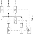
- FIG. 1b An additional embodiment is illustrated in FIG. 1b .
- a fill manifold 141 may be associated with the fill valve 120 and compression pump 105.
- a separate exhaust manifold 142 may be associated with the vacuum source 110 and exhaust valve 130,
- Cell valves 125a-N may be associated with both the fill manifold 141 and exhaust manifold 142. It is understood that cell valves 125a-N in this embodiment may have a 3-way function: open to fill, open to exhaust, and closed,
- each cell may have a first valve to connect to the fill manifold 141 and a second valve to connect to the exhaust manifold 142.
- transducer 115 associated with fill manifold 141
- transducer 115 may be calibrated with respect to atmosphere by means of a separate shunt valve (not shown) associated either directly with transducer 115 or with the fill manifold 141.
- Exhaust manifold 142 may also be in communication with its own transducer 115' to monitor the pressure within the exhaust manifold.
- Transducers 115 and 115' may provide sensor data as well to controller 145,
- each valve 125a-N may be in fluid connection with a flow sensor 150a-N in-line with the connection to its respective cell.
- Flow sensors 150a-N may provide sensor data as well to controller 145.
- a flow sensor 150a-N may be used to monitor that its respective valve 125a-N is completely open. If a valve is blocked or otherwise impeded, the fluid flow through it may not match an expected flow profile as determined by controller 145.
- a flow sensor 150a-N could provide the controller 145 with data to indicate a fault with the associated valve 125a-N. The controller 145 may then be programmed to notify a user of the valve flow fault condition.
- the flow sensors 150a-N may be used to accurately determine the rate of air flow into or from a particular cell, or the total amount of air pumped into (or exhausted from) a cell over a fixed period of time. Based on the data from the flow sensor 150a-N, the fill/exhaust rate for a cell may be adjusted by controller 145 to control the amount of time required for a fill or exhaust step. A clinician developing a particular therapy protocol may then be able to program a fill or exhaust time as part of the protocol. Such time-based programming may be easier for a clinician to use instead of flow rates and volumes.
- a pressure sensor 155a-N may be associated with each cell to measure the fluid pressure within the cell during its operation.
- the pressure sensors 155a-N may also provide data to controller 145 so that the controller may be able to control the operation of the compression device.
- a pressure sensor 155a-N associated with its respective cell may provide direct indication of a pressurization or depressurization profile of the cell.
- transducer 115 may measure the pressure of any cell communicating with common manifold 140 by means of its respective valve 125a-N.
- Controller 145 may compare an individual cell pressure against a pre-programmed cell pressure profile. If a cell is unable to sustain an expected pressure, a leak condition may be determined. The controller 145 may then be programmed to notify a user of the leak condition.
- FIG, 1a does not explicitly illustrate the use of either flow or pressure sensors between the valves 125a-N and their respective cells, it may be appreciated that either flow sensors, pressure sensors, or both types of sensors may be included in alternative embodiments. Similarly, although FIG. 1b illustrates the use of such sensors, it should be understood that other embodiments may lack either one or both types of sensors.
- the pneumatic compression device may be operated to provide a variety of therapeutic protocols.
- a therapeutic protocol may be defined as a specific sequence of operations to inflate (fill) and deflate (exhaust) one or more cells while they are in contact with a patient,
- Therapeutic protocols may include, in a non-limiting example, a list of a sequence of cells to be activated, an inflation or deflation pressure measure for each cell, an amount of time during cell inflation or deflation, and a time between sequential cell activation.
- an initialization sequence may occur prior to the start of a therapeutic protocol.
- fill valve 120 may be closed, thereby isolating the compression pump 105 from a manifold (either 140 or 141), and exhaust valve 130 may be opened to atmosphere 135.
- the cell valves 125a-N may then be opened thereby placing each cell in fluid communication with either the common manifold 140 or exhaust manifold 142. In this manner, all the cells to be vented to the atmosphere.
- exhaust valve 130 may be opened to vacuum source 110 to permit rapid evacuation of the cells.
- the controller 145 may determine whether a minimum pressure threshold has been reached based on information received from the transducer 115 (for a common manifold configuration) or from transducer 115' (for a dual manifold configuration). The controller 145 may also receive sensor data from the cell specific pressure sensors 155a-N. In one embodiment, when the minimum pressure threshold is reached, the controller 145 may send operation commands to exhaust valve 130 to close. In another embodiment, the controller 145 may also provide operation commands to the cell valves 125a-N to close. In yet another embodiment, the controller 145 may initiate a therapeutic protocol. It may be appreciated that the initialization sequence may occur while the cells are in contact with the patient, before the cells are affixed onto the patient, or after a protocol has been completed.
- a protocol may incorporate one or more cell fill phases, As a non-limiting example of such a fill phase, the following operating sequence may occur.
- One or more cell valves 125a-N may be opened along with the fill valve 120 thereby allowing the one or more cells to be in fluid communication with the compression pump 105.
- one or more of the cell valves 125a-N may open to the common manifold.
- one or more of the cell valves 125a-N may be configured to open the cells to communicate with the fill manifold 141 only.
- a cell valve such as 125a, connected to a cell affixed to a distal portion of the patient, may be opened or remain open to the fill manifold 141 or common manifold 140 for inflation while cell valves associated with more proximal cells are closed to that manifold.
- the cell e.g. cell A
- the cell pressure may be monitored by the controller 145 via the transducer 115 and/or a pressure sensor 155a associated specifically with that cell.
- the amount of pressure sensed by the transducer 115 may differ from the cell pressure at a particular cell. For example, pressure losses may occur between the transducer 115 and a cell. Accordingly, the controller 145 may access a lookup table to determine the threshold at which the pressure sensed by the transducer 115 is appropriate to close the cell valve 125a-N corresponding to the cell.
- an opened cell valve such as 125a
- the opened cell valve may be modulated to control the fill rate of the corresponding cell.
- the opened cell valve may be modulated based on time and/or pressure.
- a cell valve that is being modulated on a time basis may be opened for a first period of time and closed for a second period of time as the cell is inflating.
- a cell valve that is being modulated on a pressure basis may be opened while the cell pressure increases and closed for a period of time during the inflation cycle.
- the pressure increase may be determined by measuring an initial cell pressure before opening the cell valve and the cell pressure as the cell valve is open.
- the cell valve When the difference between the initial cell pressure and the inflating cell pressure is substantially equal to a specific value, the cell valve may be closed.
- the duty cycle at which the cell valve is modulated may be any value and may be specifically programmed by a user or clinician.
- the controller 145 may determine when to open and close the cell valve. For pressure-based modulation, any one or more of transducer 115 or cell specific pressure sensors 155 may provide pressure data to the controller 145 to assist in determining when to open and/or close the cell valve during modulation.
- Modulation may be performed to ensure that the cell pressure does not increase too quickly for a given protocol.
- a lymphedema patient may be treated with a protocol requiring slowly inflating and deflating cells.
- an arterial patient may require a protocol capable of rapid inflation and deflation cycles.
- cells may be of varying size. For example, cells in a device designed for a child may be smaller than cells in a device designed for an adult.
- the compression pump 105 may have a relatively fixed flow rate. As such, modulation may be used to ensure that cell inflation is performed at a proper rate.
- a cell valve such as 125a
- a flow sensor such as 150a may monitor the fluid flow rate into the cell. The data from the flow sensor may be provided to controller 145 so that the controller may be able to adjust the aperture in the cell valve.
- a cell valve such as 125a may incorporate a one-way valve.
- valve 125a is opened to allow cell A to be filled by common manifold 140 or fill manifold 141, and then valve 125b is opened to allow cell B to be pressurized
- a one-way valve incorporated in valve 125a will prevent transient depressurization of cell A when valve 125b is opened to initially evacuated cell B.
- a compression pump 105 that operates with a variable flow rate may be used. Additional methods of modulating pressure may also be performed and will be apparent to one of ordinary skill in the art based on this disclosure.
- the controller 145 may close the cell valve 125a corresponding to the cell.
- a protocol may also incorporate one or more cell exhaust phases.
- One or more cell valves 125a-N may be opened along with the exhaust valve 130, thereby allowing the one or more cells to be in fluid communication with either the vacuum source 110 or the atmosphere 135.
- one or more of the cell valves 125a-N may open to the common manifold.
- the one or more cell valves 125a-N may be configured to open the cells to communicate with the exhaust manifold 142 only.
- a cell valve such as 125a, connected to a cell affixed to a distal portion of the patient, may be opened or remain open to the exhaust manifold 142 or common manifold 140 for deflation while cell valves associated with more proximal cells are closed to that manifold.
- the cell e.g. cell A
- the cell pressure may be monitored by the controller 145 via transducer 115 for a common manifold configurations or transducer 115' for independent manifold configurations, a pressure sensor 155a associated specifically with that cell, or by both.
- the amount of pressure sensed by the transducer 115 or transducer 115' may differ from the cell pressure at a particular cell. For example, pressure losses may occur between the transducer 115 (or 115') and a cell. Accordingly, the controller 145 may access a lookup table to determine the threshold at which the pressure sensed by the transducer 115 (or 115') is appropriate to close the cell valve 125a-N corresponding to the cell.
- an opened cell valve such as 125a
- the opened cell valve may be modulated based on time and/or pressure.
- a cell valve that is being modulated on a time basis may be opened for a first period of time and closed for a second period of time as the cell is deflating
- a cell valve that is being modulated on a pressure basis may be opened while the cell pressure decreases and closed for a period of time during the exhaust cycle. The pressure decrease may be determined by measuring an initial cell pressure before opening the cell valve and the deflated cell pressure as the cell valve is open.
- the cell valve When the difference between the initial cell pressure and the cell pressure is substantially equal to a specific value, the cell valve may be closed.
- the duty cycle at which the cell valve is modulated may be any value and may be specifically programmed by a user or clinician.
- the controller 145 may determine when to open and close the cell valve.
- any one or more of transducers 115, 115', or cell specific pressure sensors 155 may provide pressure data to the controller 145 to assist in determining when to open and/or close the cell valve during modulation.
- Modulation may be performed to ensure that the cell pressure does not decrease too quickly, which could cause a reverse gradient.
- cells may be of varying size. For example, cells in a device designed for a child may be smaller than cells in a device designed for an adult.
- the vacuum source 110 may have a relatively fixed flow rate, and venting to atmosphere 135 may occur due to unregulated, passive exhaust. As such, modulation may be used to ensure that cell deflation is performed at a proper rate.
- a cell valve such as 125a
- a flow sensor such as 150a may monitor the fluid flow rate into the cell. The data from the flow sensor may be provided to controller 145 so that the controller may be able to adjust the aperture in the cell valve.
- a cell valve such as 125a may incorporate a one-way valve.
- valve 125a is opened to allow cell A to be evacuated by exhaust manifold 142, and then valve 125b is opened to allow cell B to be evacuated, a one-way valve incorporated in valve 125a will prevent transient re-pressurization of cell A when valve 125b is opened to previously pressurized cell B.
- a vacuum source 110 that operates with a variable flow rate may be used. Additional methods of modulating pressure may also be performed and will be apparent to one of ordinary skill in the art based on this disclosure,
- the controller 145 may close the cell valve 125a corresponding to the cell,
- a therapeutic protocol may be composed of any variety of sequences of cell inflation and deflation steps.
- Cells may be inflated and deflated in a specific order, and multiple cells may be inflated or deflated either in synchrony or in a staggered fashion.
- the cells may be held at a particular inflation or deflation pressure for a specific amount of time.
- a specific protocol may be repeated with some lag time between repeats.
- a first protocol may be followed by a second and different protocol.
- a plurality of cell valves 125a-N may be opened simultaneously to inflate the plurality of respective cells simultaneously.
- the controller 145 may close the cell valve 125a-N for the cell.
- the pressure thresholds for all the cells may be identical or they may differ. For example, the pressure threshold for a cell at a distal position on a patient may be higher than a cell more proximally located. As a result, a pressure gradient may be developed by the cells from a greater pressure at the distal point, to a lesser pressure at the proximal point. The cells may then be deflated simultaneously until they all reach an ambient pressure. Alternatively, only selected cells may be deflated.
- the cell valves 125a-N may not be opened simultaneously when the cells are deflated, but rather may be opened in a staggered fashion.
- fill valve 120 may be closed, and exhaust valve 130 may be opened to either the vacuum source 110 or to atmosphere 135,
- a first cell valve, such as 125a may be opened to release the pressure in the corresponding cell.
- a second cell valve, such as 125b may be opened to release the pressure in the corresponding cell. The process may be repeated until each cell valve 125a-N has been opened,
- a plurality of cell valves 125a-N may be modulated simultaneously.
- one or more cell valves may be opened and/or closed according to a modulation schedule. For example, for a time-based modulation scheme having a 50% duty cycle, half of the cell valves 125a-N may be open and half of the cell valves may be closed at any time.
- FIG. 2 depicts illustrative data communication exchanges between a compression system and a variety of electronic devices.
- the compression system may include a controller system 210 and at least one compression sleeve (such as a boot) 205.
- the compression sleeve 205 may be designed to deliver compression therapy to specific body parts.
- a torso sleeve there may be a torso sleeve, an arm sleeve, a shoulder sleeve, a thigh sleeve, a calf sleeve, an ankle sleeve, a back sleeve, a chest sleeve, a buttocks sleeve, a genital sleeve, or a foot sleeve.
- the individual sleeves may be combined into a single unit such as a sleeve comprising a torso element, a shoulder element, and an arm element.
- a sleeve may include a combination of a thigh element, a calf element, an ankle element, and a foot element.
- a patient may wear more than one sleeve to deliver compression therapy to non-contiguous body parts such as the chest and lower arm.
- Other combinations of sleeves or sleeve elements may also be anticipated.
- the controller system may include the pneumatic components as illustrated in FIGS. 1a , b.
- sleeve 205 may receive air pressure from manifold lines 215, or vacuum from an exhaust manifold 220.
- Sleeve 205 may also provide sensor data over a number of sensor lines such as 225.
- the sensor data may include one or more of individual cell pressure, cell volumetric data based on cell surface deformation, cell volume, the temperature within the sleeve, or data related to a pulse sensed from a patient body part inserted into the sleeve.
- it may be desirable for a patient to wear an undergarment beneath the compression sleeve, to reduce perspiration build-up in the sleeve and prevent patient skin chafing.
- the undergarment may include a tag such as a small magnet, a barcode tag, or a radiofrequency identifying tag,
- the sleeve may then include a sensor for the undergarment tag, such as an optical sensor, a magnetic sensor or a radiofrequency sensor.
- the sensor data may be incorporated into operational therapy data stored by one or more memory devices within the controller.
- the memory devices may include transitory (e.g. RAM) or non-transitory (e.g. ROM) memory devices.
- the operational therapy data may be stored in a removable SD card 230, a writable CDROM, a writable DVD, a USB flash drive memory device, a flash memory card, or a miniature tape drive, among others.
- the operational therapy data may be transmitted to any one or more parties interested in the patient's compliance with a therapy protocol.
- compliance data recipients may include any one or more of a manufacturer or supplier of the equipment, a medical practitioner such as a physician and/or therapist, a medical facility, a medical insurance provider, family members, a clinical therapy follow-up repository, and/or an accountable care organization.
- the raw operational therapy data may be supplied to the interested parties in order to determine patient compliance.
- the operational therapy data may be compared to some known standard data, and the difference between the operational data and the standard data may be supplied as an indicator or metric of patient compliance.
- a standardized report including summary data for a given therapeutic session may be supplied. Such a report may include one or more of a date and time of the beginning of a therapy session, a length of time of the therapy session, and a compliance metric demonstrating that the patient was actually using the compression therapy system during the session. The compliance metric may be calculated, at least in part, based on the standard data.
- the controller may provide a status code on an output device to the patient after the patient presses a push-button to indicate that a therapy session has been completed.
- the status code may incorporate date, time, and a compliance metric in a manner that the user may not be able to decode.
- the patient may then contact a recipient of the data either via e-mail, telephone, or by entering the status code into a recipient-controlled website, thereby providing the compliance metric or status value to the recipient.
- the standard data may be calculated as an average of data from a number of individual users of the compression therapy device using a common therapy protocol. In another embodiment, the standard data may be obtained from the patient/user of a therapy device under supervised therapy conditions.
- the compliance data - as a stream of operational data, difference data, report, compliance metric, or status code - may be presented to a recipient across a number of communication channels.
- the compliance data may be stored in an SD card 230 or other removable memory device such as a USB flash drive, while the card is associated with the controller 235.
- the data may then be uploaded 240 to a patient based computer 247 or other electronic device.
- the electronic device 247 may communicate the data via a wireless connection or a wired connection 262 to a server 295,
- the controller 210 may include a wireless communication interface 255.
- the wireless communication interface 255 may communicate over a wireless interface 250 to the patient's own electronic device 247.
- the operational data may be transmitted from the controller to the patient computer 260,
- a wired interface between the controller and the user computer 247 may permit wire-based communication transfer 245.
- controller may have a personal network wireless interface 255 that may communicate 265 through a cell phone 270 to a data server 295.
- the controller wireless communication link 255 may transmit 275 data directly to a wireless interface 285 of a remote electronic device 280.
- the controller 210 may convey this information to the recipients after each therapy session, or only after sessions in which the patient compliance has been detected as being less than complete compliance. It may be appreciated that the communications methods disclosed above are merely examples, and may not be taken as limiting the communication of operational therapy data and/or a compliance metric between the controller 210 and a recipient of the data.
- FIG. 3 is a block diagram of an embodiment of hardware that may be used to contain or implement program instructions for controller 145. Some or all of the below-described hardware may be incorporated in the controller 145.
- a bus 328 may serve as the main information highway interconnecting the other illustrated components of the hardware.
- CPU 302 is the central processing unit of the system, performing calculations and logic operations required to execute a program.
- Read only memory (ROM) 318 is one example of a static or non-transitory memory device
- RAM random access memory
- FIG. 3 is a block diagram of an embodiment of hardware that may be used to contain or implement program instructions for controller 145. Some or all of the below-described hardware may be incorporated in the controller 145.
- a bus 328 may serve as the main information highway interconnecting the other illustrated components of the hardware.
- CPU 302 is the central processing unit of the system, performing calculations and logic operations required to execute a program.
- Read only memory (ROM) 318 is one example of a static or non-transitory
- a controller 304 may interface the system bus 328 with one or more optional disk drives 308, These disk drives may include, for example, external or internal DVD drives, CD ROM drives, or hard drives,
- Program instructions may be stored in the ROM 318 and/or the RAM 320.
- program instructions may be stored on a computer readable medium such as a compact disk or a digital disk or other recording medium, a communications signal or a carrier wave.
- operational therapy data may be stored on a removable memory devices 330 that may include, as non-limiting examples, a removable disc, a removable card, a removable memory stick, a flash drive, a removable SIM chip, a writable CD ROM or DVD disk, and/or a miniature data tape, Such devices may be used to transfer data from the controller to another data receiving device such as a home computer.
- An optional display interface 322 may permit information from the bus 328 to be displayed on the display 324 in audio, graphic or alphanumeric format.
- Additional output interface devices may include a printer, a barcode printer, an LCD panel device, a touch screen device, an audio device, an LED panel, an OLED panel device, one or more individual LEDs, either as separate displays or grouped together, and a haptic device.
- Communication with external devices may occur using various communication ports 326. For example, communication with the fill valve 120, exhaust valve 130, and/or the cell valves 125a-N may occur via one or more communication ports 326. Controller 145 may also provide command data over communication ports 326 to valves 120, 130, and 125a-N to direct their respective operations.
- the hardware may also include an interface 312 which allows for receipt of data from input devices such as a keyboard 314 or other input device 316 such as a touch screen, a mouse, remote control, pointing device, pushbutton, haptic device, a voice recognition device, a proximity sensor, a motion detection sensor, a multi-axis accelerometer, a directional pad, and/or joystick,
- input devices such as a keyboard 314 or other input device 316 such as a touch screen, a mouse, remote control, pointing device, pushbutton, haptic device, a voice recognition device, a proximity sensor, a motion detection sensor, a multi-axis accelerometer, a directional pad, and/or joystick
- transducers 115 and 115', pressure sensors 155a-N, flow sensors 150a-N, as well as sensors communicating data related to the change in shape or volume of the cells, cell or sleeve temperatures, or sensors to detect the pulse associated with a body part inserted into a sleeve may
- the controller 145 may store and/or determine settings specific to each cell. For example, the controller 145 may determine one or more pressure thresholds for each cell. Moreover, the controller 145 may prevent the pneumatic compression device from being used improperly by enforcing requirements upon the system. For example, the controller 145 may be programmed so that distal cells in a therapeutic protocol are required to have higher pressure thresholds than proximal cells. The controller may override instructions received from a user via the user interface that does not conform to such pressure threshold requirements. In an embodiment, the pressure thresholds of one or more cells may be adjusted to meet the pressure threshold constraints.
- controller 145 may provide a compression device user with an interface to permit the user to program the control to provide a variety of therapeutic protocols for patients.
- the interface may be displayed on the control display, such as a flat panel display.
- Input devices such as a mouse, keypad, or stylus may be used by the user to provide data to define a particular therapeutic protocol.
- a push-button device be activated by a user to indicate that data from the controller may be transmitted to a receiving unit such as a computer, cell phone, or wireless hot-spot.
- the controller may record the protocols on a memory or disk device for future use.
- a user may be presented with a list of previously stored therapeutic protocols from which to choose for a particular patient.
- a user may define a therapeutic protocol for a patient on an as-needed basis.
- a user may choose a stored protocol and modify it.
- the controller 145 may also record sensor readings obtained during a particular therapy session.
- sensors may include pressure sensors, timing sensors, fluid flow sensors, temperature sensors, inflatable cell material deformation sensors, and other.
- Sensor readings may include, without limitation, the time a sensor reading is made, cell pressures, cell volumes, cell inflation data, air or vacuum air flow values, and/or temperatures taken from an interior of the sleeve or compression device.
- the controller may also record patient related data such as blood pressure, EKG, or blood oxygen saturation levels measured during a therapeutic session, as well as a date and time for the session, The controller may also record therapy notes entered by the user.
- controller 145 may also include a number of communications interfaces to a wireless local area network, a localized personal area network (such as a Bluetooth connection or ZigBee connection), or a telephony device.
- Such communication devices may include, without limitation, an Ethernet connection device connected to a computing device, an infrared connecting device connected to a computing device, and a serial connection device connected to a computing device.
- Telephony devices may include, without limitations, cell phones, land-line phones, voice modems, TRx devices, fax machines, and other communications devices based on telephone technology.
- Such communication interfaces may permit the controller to be monitored remotely by a clinician to obtain performance data or patient compliance data.
- Such communication interfaces may also permit a remote clinician to program the controller.
- a cell phone may have an application that may bring up a user-friendly programming interface to permit ease of reprogramming.
- a remote computer may display a web-enabled display for programming, data assessment, and/or analysis,
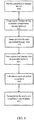
- FIG. 4 discloses a flow chart of one embodiment of a method of determining use compliance of a compression therapy device by a patient.
- a compression therapy device as substantially disclosed above, may be provided to a patient 410.
- the compression therapy device may include an inflatable compression sleeve, a source of fluid - such as a gas - for inflating the sleeve, and a controller unit to control the inflation and deflation of the sleeve and/or the individual cells comprising the sleeve.
- the controller may include one or more sensors associated with the sleeve, sensors associated with the inflation and deflation devices for the sleeve, at least one non-transitory memory device, and at least one communication device.
- the controller may also include user input devices.
- the patient may then cause the compression therapy device to initiate a therapy protocol 415.
- sensors associated with the compression device may acquire and identify relevant operational therapy data from the compression device sensors 420.
- the operational therapy data may include, without limitation, pressures associated with the cells in the compression sleeve, air flow into and out from the cells, data associated with the volume attained by the cells during inflation and deflation during a therapy session, the temperature in the interior of the compression sleeve, and data associated with the pulse of the patient's body part inserted into the sleeve.
- the operational therapy data may also include a start time for a therapy protocol, a stop time for the therapy protocol, a rate of inflating at least one inflatable cell in the compression sleeve, a rate of deflating at least one inflatable cell in the compression sleeve, a time course of inflating at least one inflatable cell in the compression sleeve, a time course of deflating at least one inflatable cell in the compression sleeve, a time course of a pressure within at least one inflatable cell in the compression sleeve, a rate of pressurizing at least one inflatable cell in the compression sleeve, a start time of a compression therapy session, and a stop time of a compression therapy session.
- the operational therapy data may then be stored in the controller memory, such as a non-transitory memory including either a non-removable memory or a removable memory 425.
- the controller may then calculate a metric of patient compliance based, at least in part, on the operational therapy data 430.
- the calculation may include calculating a difference between the operational therapy data and a standard therapy data set.
- the standard therapy data set may be derived from an average of operational therapy data obtained from a number of patients undergoing the same therapy protocol.
- the standard therapy data set may be derived from data taken of the patient during a supervised therapy session while undergoing the same therapy protocol.
- the supervised data set may be taken while a physician or therapist assures that the patient is using the compression therapy device correctly, and uses it for a complete therapy session. An average of several sessions may be calculated to insure statistical accuracy and account for normal variation in therapy device use.
- the standard therapy data may also depend, at least in part, on the type of the compression sleeve used by the patient, either size, construction, or part of the body for which it may be designed.
- the standard therapy data set may be stored in a memory storage device of the controller.
- the metric may include one or more of a numerical value, a text string, or a graphical representation, either separately or in combination.
- the compliance metric may represent, as examples, a binary report on compliance for a particular therapy session (patient complied/did not comply), or a probability value that a patient was compliant during a therapy session.
- the metric may be calculated based on the actual sensor data taken during a therapy session compared to expected sensor data for a compliant patient during a session.
- Data related to expected sensor results may include the rates of cell filling, time for cell or sleeve inflation, final cell pressures, or final cell volumes during a particular protocol.
- a patient body part such as a leg
- the patient is not properly affixing the sleeve about the body part
- the fluid flow rate into the cells may be greater at the end of an inflation cycle if there is no body part to resist the increased fluid flow.
- Related measurements may include the final cell pressure (less than expected if the body part was within the sleeve), and final cell volume (greater than expected).
- a temperature sensor may be associated with the sleeve, thus, a session with a non-compliant patient may result in the temperature sensor recording ambient air temperature as opposed to the temperature of the patient's body part within the sleeve.
- the patient may receive an undergarment to be worn under the compression sleeve.
- the undergarment may include one or more indicator devices such as a readable (barcode) tag, a radiofrequency identification device (RFID), or one or more small magnets.
- An additional embodiment may include a strain gauge associated with one or more inflatable cells.
- a strain gauge may measure the deformation of the cell surface and may indicate the presence or absence of a body part which could deform the surface of the cell upon inflation.
- a sensor capable of recording a patient's pulse may not record a pulse if the body part is not within the sleeve. It may be appreciated that other measurements from sensors associated with the inflatable sleeve may be able to distinguish a compliant patient from a non-compliant patient,
- the metric may be transmitted to at least one compliance data recipient 435.
- the manner in which the compliance metric is transmitted can be based on a number of different transmission routes as disclosed above.
- the communication device of the controller may transmit the metric directly via a local or wide area wireless network to a computing device such as a server controlled at least in part by a compliance data recipient.
- the metric may be transmitted via a localized personal area network to a cell phone that can communicate with a recipient.
- the controller communication interface may include a serial link to a telephone device for similar communication to the recipient.
- the controller may be used to transmit the metric over either an ethernet connection, wireless RF connection, or IR connection to a patient's personal computing device.
- the personal computing device may store the metric data until the user transmits it to the recipient by uploading a file to a server, e-mailing the data to an e-mail address, or entering the data into a website, any one or more of which may be controlled at least in part by the recipient.
- the data may be stored by the controller on a removable memory or data storage device (such as a SIM chip). The removable memory device may then be put into data communication with the patient's personal computing device, and the data within the removable memory storage device may be provided to the recipient by e-mail, file transfer, or website entry.
- the controller may retain the one or more compliance metrics after a therapy session until the patient activates a pushbutton or other input device, Upon receipt of the patient input, the controller may provide the patient with the compliance metric, for example by an output display, that the patient may relay to the compliance data recipient either by e-mail, by entry into a website, or by phone. In another embodiment, the patient may request the controller to print a copy of a compliance metric or other report regarding the therapy session, and the patient may transmit the printed copy by mail to at least one compliance data recipients
- the compliance data may be received by one or more compliance data recipients, it may be understood that the data may also be shared among several such recipients.
- a provider of the compression therapy system may receive the compliance data or metric and then relay that information to a provider of health care insurance or to a therapist monitoring the patient's progress.
- the initial recipient of the compliance data may forward the data intact or reduced to a summary report to the secondary recipients.
- the report may include one or more of text, numerical data, charts, and/or graphs.
- the report to the secondary recipients may include compliance data for a single patient during a single therapy session, a single patient including compliance data from multiple therapy sessions, or multiple patients including compliance data from one or more therapy sessions.
- the calculation of the compliance metric is not necessarily restricted to the therapy system controller, and that standard therapy data need not be located only in the memory of the controller.
- the raw operational therapy data may be transmitted to a computing device (such as a server) controlled at least in part by one or more of the compliance data recipients.
- the recipient controlled device may then calculate the compliance metric based at least in part on the received raw operational data and a standard therapeutic data set located in memory associated with the recipient controlled computing devices.
- the pneumatic compression device may be portable.
- the pneumatic compression device may include a user interface that enables the user to interact with the controller 145.
- the user interface may include a display and one or more input devices, such as a keypad, a keyboard, a mouse, a trackball, a light source and light sensor, a touch screen interface and/or the like,
- the one or more input devices may be used to provide information to the controller 145, which may use the information to determine how to control the fill valve 120, exhaust valve 130, and/or the cell valves 125a-N.
Landscapes
- Health & Medical Sciences (AREA)
- Engineering & Computer Science (AREA)
- General Health & Medical Sciences (AREA)
- Public Health (AREA)
- Epidemiology (AREA)
- Medical Informatics (AREA)
- Biomedical Technology (AREA)
- Primary Health Care (AREA)
- Physical Education & Sports Medicine (AREA)
- Life Sciences & Earth Sciences (AREA)
- Business, Economics & Management (AREA)
- General Business, Economics & Management (AREA)
- Biophysics (AREA)
- Pain & Pain Management (AREA)
- Rehabilitation Therapy (AREA)
- Animal Behavior & Ethology (AREA)
- Veterinary Medicine (AREA)
- External Artificial Organs (AREA)
- Massaging Devices (AREA)
- Measuring And Recording Apparatus For Diagnosis (AREA)
Claims (13)
- Kompressionstherapievorrichtung, um Kompressionstherapie für einen Patienten bereitzustellen und um die Einhaltung der Therapie durch den Patienten zu überwachen, umfassend:einen Kompressor (105);eine aufblasbare Kompressionsmanschette (205), umfassend: eine Mehrzahl von Zellen und eine Mehrzahl von 3-Weg Funktionsventilen (125aN), betriebsmäßig gekoppelt mit und entsprechend der Mehrzahl von Zellen, wobei jedes 3-Weg Funktionsventil dazu eingerichtet ist, durch ein Platzieren der Zelle in Fluidverbindung mit dem Kompressor die Zelle zum Befüllen aufzublasen, durch das Platzieren der Zelle in Fluidverbindung mit der Atmosphäre die Zelle zur Entleerung zu deflationieren, und zu schließen; undeine Steuer-/Regeleinheit (145), um das Aufblasen der Kompressionsmanschette zu steuern, wobei die Steuer-/Regeleinheit wenigstens einen Sensor, welcher der Kompressionsmanschette zugeordnet ist, wenigstens eine dauerhafte Speichervorrichtung, und wenigstens eine Kommunikationsvorrichtung umfasst, wobei die Steuer-/Regeleinheit dazu eingerichtet ist:
die Kompressionstherapievorrichtung zu initiieren, wobei das Initialisieren umfasst:Öffnen wenigstens eines 3-Weg Funktionsventils, um wenigstens eine Zelle zu entleeren, den Druck der wenigstens einen Zelle herabzusetzen, um eine anfängliche minimale Druckschwelle zu erreichen; und Schließen des wenigstens einen 3-Weg Funktionsventils, sobald die anfängliche minimale Druckschwelle erreicht wird;Ausführen (415) wenigstens eines Kompressionstherapieprotokolls mit der Kompressionstherapievorrichtung; undIdentifizieren (420) durch den wenigstens einen Sensor operativer Therapiedaten während der Ausführung von wenigstens einem Kompressionstherapieprotokoll, wobei die Identifizierung der operativen Therapiedaten umfasst:Messen durch den wenigstens einen Sensor von Sensordaten, welche Informationen in Bezug auf Leistungsvariablen in Bezug auf einen Betrieb der Mehrzahl von Zellen für jede der Mehrzahl von Zellen zur Vervollständigung des wenigstens einen Kompressionstherapieprotokolls umfassen;Speichern (425) durch die wenigstens eine Speichervorrichtung der operativen Therapiedaten auf der Speichervorrichtung, wobei die operativen Therapiedaten wenigstens die Sensordaten umfassen;Berechnen (430) einer Metrik einer Patientenkonformität, welche wenigstens teilweise auf den operativen Therapiedaten basiert, wobei das Berechnen der Metrik der Patientenkonformität umfasst: Identifizieren eines bestehenden Therapiedatensatzes, Berechnen einer Differenz zwischen den operativen Therapiedaten und dem bestehenden Datensatz, und Bestimmen der Metrik der Patientenkonformität basierend auf der berechneten Differenz; undÜbertragen (435) der Metrik der Patientenkonformität an wenigstens einen Konformitätsdatenempfänger. - Vorrichtung nach Anspruch 1, wobei die aufblasbare Kompressionsmanschette eine oder mehrere der Folgenden umfasst: eine Brustmanschette, eine Fußmanschette, eine Knöchelmanschette, eine Wadenmanschette, eine Unterschenkelmanschette, eine Hüftmanschette, eine Oberschenkelmanschette, eine Unterarmmanschette, eine Oberarmmanschette, eine Handgelenkmanschette, eine Handmanschette, eine Brustmanschette, eine Einzelschultermanschette, eine Rückenmanschette, und Kombinationen davon.
- Vorrichtung nach Anspruch 1, wobei der wenigstens eine Sensor einen oder mehrere der Folgenden umfasst: einen Drucksensor, einen Zeitgebersensor, einen Strömungssensor, einen Temperatursensor, einen Materialverformungssensor, einen optischen Sensor, einen magnetischen Sensor, einen Hochfrequenzsensor, und einen Dehnungsmesser.
- Vorrichtung nach Anspruch 1, wobei die wenigstens eine Speichervorrichtung entfernbar ist, wobei insbesondere die wenigstens eine Speichervorrichtung eines oder mehrere der Folgenden ist: eine entfernbare Scheibe, eine entfernbare Karte, und ein entfernbarer Speicherchip.
- Vorrichtung nach Anspruch 1, wobei die operativen Therapiedaten eines oder mehrere der Folgenden umfasst: das Therapieprotokoll, einen Anzahl an Protokollwiederholungen während einer klinischen Therapiesitzung, eine Dauer von jeder Protokollwiederholung, eine Startzeit für das Therapieprotokoll, eine Stoppzeit für das Therapieprotokoll, eine Geschwindigkeit für das Aufblasen wenigstens einer aufblasbaren Zelle in der Kompressionsmanschette, eine Geschwindigkeit für das Entleeren wenigstens einer aufblasbaren Zelle in der Kompressionsmanschette, ein zeitlicher Verlauf für das Aufblasen wenigstens einer aufblasbarer Zelle in der Kompressionsmanschette, eine Zeitdauer zum Aufblasen der Kompressionsmanschette, ein zeitlicher Verlauf für das Entleeren wenigstens einer aufblasbaren Zelle in der Kompressionsmanschette, ein zeitlicher Verlauf eines Drucks innerhalb wenigstens einer aufblasbaren Zelle in der Kompressionsmanschette, und eine Geschwindigkeit für das Unterdrucksetzen wenigstens einer aufblasbaren Zelle in der Kompressionsmanschette.
- Vorrichtung nach Anspruch 1, wobei die wenigstens eine Kommunikationsvorrichtung eine oder mehrere der Folgenden ist: eine Ethernet-Anschlussvorrichtung, um eine Rechenvorrichtung zu verbinden, eine Infrarot-Anschlussvorrichtung, um eine Rechenvorrichtung zu verbinden, eine Reihenschaltungsvorrichtung, eine Vorrichtung für ein kabelloses lokales Netzwerk, eine Vorrichtung für ein lokalisiertes persönliches Netzwerk, und eine Telefonvorrichtung.
- Vorrichtung nach Anspruch 1, wobei die Steuer-/Regeleinheit ferner wenigstens eine Benutzereingabeschnittstellenvorrichtung umfasst, welche eines oder mehrere der Folgenden umfasst: eine Berührungsbildschirmvorrichtung, eine Maus, eine Drucktaste, eine Spracherkennungsvorrichtung, einen Steuerknüppel, ein Steuerkreuz, einen Annäherungssensor, einen Bewegungserfassungssensor, einen mehrachsigen Beschleunigungsmesser, und eine Tastatur.
- Vorrichtung nach Anspruch 1, wobei die Steuer-/Regeleinheit ferner wenigstens eine Benutzerausgabeschnittstellenvorrichtung umfasst, welche eine oder mehrere der Folgenden umfasst: einen LCD-Bildschirm, eine Berührungsbildschirmvorrichtung, eine Audiovorrichtung, einen LED-Bildschirm, eine oder mehrere LEDs, eine haptische Vorrichtung, und einen OLED-Bildschirm.
- Vorrichtung nach Anspruch 1, wobei die Metrik der Patientenkonformität eines oder mehrere der Folgenden umfasst: wenigstens einen numerischen Wert, wenigstens eine Textzeichenfolge, wenigstens eine grafische Repräsentation, und Kombinationen davon.
- Vorrichtung nach Anspruch 1, wobei die existierenden Therapiedaten in der wenigstens einen Speichervorrichtung der Steuer-/Regeleinheit gespeichert sind.
- Vorrichtung nach Anspruch 1, wobei das Berechnen einer Metrik der Patientenkonformität ein Berechnen einer Differenz zwischen wenigstens Teilen der operativen Therapiedaten und wenigstens Teilen der Standardtherapiedaten umfasst.
- Vorrichtung nach Anspruch 1, wobei das Bereitstellen von Standardtherapiedaten ein Erhalten eines oder mehrerer der Folgenden umfasst: ein Durchschnitt einer Mehrzahl von operativen Therapiedaten, welche durch eine oder mehrere Kompressionstherapievorrichtungen erzeugt worden sind; und wenigstens ein operativer Therapiedatensatz, welcher durch die unter Aufsicht eines Therapieaufsehers verwendeten Kompressionstherapievorrichtung erzeugt worden ist.
- Vorrichtung nach Anspruch 1, wobei das Übertragen der Metrik der Patientenkonformität eine oder mehrere der Folgenden umfasst: Übertragen der Metrik über eine Ethernet-Verbindung an eine Rechenvorrichtung in Datenkommunikation mit einer Webseite, welche wenigstens teilweise durch den wenigstens einen Konformitätsdatenempfänger gesteuert ist; Übertragen der Metrik mittels einer Infrarot-Anschlussvorrichtung an eine Rechenvorrichtung in Datenkommunikation mit einer Webseite, welche wenigstens teilweise durch den wenigstens einen Konformitätsdatenempfänger gesteuert ist; Übertragen der Metrik mittels einer Reihenschaltung an eine Rechenvorrichtung in Datenkommunikation mit einer Webseite, welche wenigstens teilweise durch den wenigstens einen Konformitätsdatenempfänger gesteuert ist; Übertragen der Metrik mittels einer Reihenschaltung an eine Telefonvorrichtung in Datenkommunikation mit dem wenigstens einen Konformitätsdatenempfänger; Übertragen der Metrik mittels eines lokalisierten persönlichen Netzwerks an eine Telefonvorrichtung in Datenkommunikation mit dem wenigstens einen Konformitätsdatenempfänger; und Übertragen der Metrik mittels eines kabellosen lokalen Netzwerks an eine elektronische Vorrichtung, welche wenigstens teilweise durch den wenigstens einen Konformitätsdatenempfänger gesteuert ist.
Applications Claiming Priority (3)
| Application Number | Priority Date | Filing Date | Title |
|---|---|---|---|
| US13/915,458 US9889063B2 (en) | 2012-06-11 | 2013-06-11 | Methods and systems for determining use compliance of a compression therapy device |
| PCT/US2013/064987 WO2014200556A1 (en) | 2013-06-11 | 2013-10-15 | Methods and systems for determining use compliance of a compression therapy device |
| EP13886827.8A EP3007672B1 (de) | 2013-06-11 | 2013-10-15 | Verfahren und systeme zur bestimmung der verwendungskonformität einer kompressionstherapievorrichtung |
Related Parent Applications (1)
| Application Number | Title | Priority Date | Filing Date |
|---|---|---|---|
| EP13886827.8A Division EP3007672B1 (de) | 2013-06-11 | 2013-10-15 | Verfahren und systeme zur bestimmung der verwendungskonformität einer kompressionstherapievorrichtung |
Publications (2)
| Publication Number | Publication Date |
|---|---|
| EP3528258A1 EP3528258A1 (de) | 2019-08-21 |
| EP3528258B1 true EP3528258B1 (de) | 2021-05-12 |
Family
ID=49715866
Family Applications (2)
| Application Number | Title | Priority Date | Filing Date |
|---|---|---|---|
| EP19160890.0A Active EP3528258B1 (de) | 2013-06-11 | 2013-10-15 | Verfahren und systeme zur bestimmung der verwendungskonformität einer kompressionstherapievorrichtung |
| EP13886827.8A Active EP3007672B1 (de) | 2013-06-11 | 2013-10-15 | Verfahren und systeme zur bestimmung der verwendungskonformität einer kompressionstherapievorrichtung |
Family Applications After (1)
| Application Number | Title | Priority Date | Filing Date |
|---|---|---|---|
| EP13886827.8A Active EP3007672B1 (de) | 2013-06-11 | 2013-10-15 | Verfahren und systeme zur bestimmung der verwendungskonformität einer kompressionstherapievorrichtung |
Country Status (5)
| Country | Link |
|---|---|
| US (1) | US9889063B2 (de) |
| EP (2) | EP3528258B1 (de) |
| CN (1) | CN105530905B (de) |
| AU (2) | AU2013392051B2 (de) |
| WO (1) | WO2014200556A1 (de) |
Families Citing this family (31)
| Publication number | Priority date | Publication date | Assignee | Title |
|---|---|---|---|---|
| US9642759B2 (en) | 2007-04-13 | 2017-05-09 | Stryker Corporation | Patient support with universal energy supply system |
| US8182437B2 (en) | 2007-05-08 | 2012-05-22 | Wright Therapy Products, Inc. | Pneumatic compression therapy system and methods of using same |
| WO2013138307A1 (en) | 2012-03-12 | 2013-09-19 | Wright Therapy Products, Inc. | Compression therapy device with multiple simultaneously active chambers |
| JP6382185B2 (ja) | 2012-05-22 | 2018-08-29 | スミス アンド ネフュー ピーエルシーSmith & Nephew Public Limited Company | 創傷治療のための装置および方法 |
| JP2015528335A (ja) | 2012-08-18 | 2015-09-28 | ライト セラピー プロダクツ、インク. | 圧迫療法処置の部分として身体部位の寸法を決定する方法 |
| CN105492035B (zh) | 2013-03-14 | 2019-06-14 | 史密夫和内修有限公司 | 用于应用减压治疗的系统和方法 |
| US9737649B2 (en) | 2013-03-14 | 2017-08-22 | Smith & Nephew, Inc. | Systems and methods for applying reduced pressure therapy |
| US9295605B2 (en) | 2013-12-02 | 2016-03-29 | Wright Therapy Products, Inc. | Methods and systems for auto-calibration of a pneumatic compression device |
| US10470967B2 (en) | 2014-01-20 | 2019-11-12 | Tactile Systems Technology, Inc. | Bespoke compression therapy device |
| US10292894B2 (en) | 2014-02-11 | 2019-05-21 | Tactile Systems Technology, Inc. | Compression therapy device and compression therapy protocols |
| US12133789B2 (en) | 2014-07-31 | 2024-11-05 | Smith & Nephew, Inc. | Reduced pressure therapy apparatus construction and control |
| HK1254210A1 (zh) * | 2015-07-08 | 2019-07-12 | 细胞保护装置股份有限公司 | 用於对受试者执行远程缺血性调节(ric)的可配置系统 |
| CN108292529A (zh) | 2015-10-07 | 2018-07-17 | 史密夫和内修有限公司 | 用于应用减压治疗的系统和方法 |
| US10667984B2 (en) | 2015-12-18 | 2020-06-02 | Stryker Corporation | Systems and methods for operating patient therapy devices |
| EP3413945B1 (de) | 2016-02-12 | 2024-04-24 | Smith & Nephew, Inc. | Systeme und verfahren zum nachweis der betriebsbedingungen einer druckreduzierten therapie |
| US11602461B2 (en) | 2016-05-13 | 2023-03-14 | Smith & Nephew, Inc. | Automatic wound coupling detection in negative pressure wound therapy systems |
| CN105943333A (zh) * | 2016-06-15 | 2016-09-21 | 邹城众达知识产权咨询服务有限公司 | 一种基于移动通讯网的会员制心脑血管护理装置及方法 |
| CZ307756B6 (cs) * | 2016-08-15 | 2019-04-17 | Fakultní nemocnice Hradec Králové | Zařízení s obvazovým materiálem s regulovatelným přítlakem |
| US12263294B2 (en) | 2016-09-28 | 2025-04-01 | T.J.Smith And Nephew, Limited | Systems and methods for operating negative pressure wound therapy devices |
| AU2017335635B2 (en) | 2016-09-29 | 2023-01-05 | Smith & Nephew, Inc. | Construction and protection of components in negative pressure wound therapy systems |
| EP3592313B2 (de) | 2017-03-07 | 2024-12-18 | Smith & Nephew, Inc | Verbesserte drucktherapiesysteme und verfahren mit einer antenne |
| US11410771B2 (en) | 2017-06-01 | 2022-08-09 | Stryker Corporation | Patient care devices with open communication |
| WO2019014141A1 (en) | 2017-07-10 | 2019-01-17 | Smith & Nephew, Inc. | SYSTEMS AND METHODS FOR INTERACTING DIRECTLY WITH A COMMUNICATION MODULE OF A WOUND PROCESSING APPARATUS |
| USD870297S1 (en) | 2017-09-28 | 2019-12-17 | Tactile Systems Technology, Inc. | Trunk garment |
| EP4079270B1 (de) | 2017-11-06 | 2025-08-13 | Tactile Systems Technology, Inc. | Kompressionskleidungssysteme |
| GB201820668D0 (en) | 2018-12-19 | 2019-01-30 | Smith & Nephew Inc | Systems and methods for delivering prescribed wound therapy |
| EP3931840A1 (de) | 2019-02-27 | 2022-01-05 | T.J.Smith And Nephew, Limited | Systeme und verfahren zur synchronisierung einer geräteuhr in systemen zur wundüberwachung und/oder behandlung |
| CZ308066B6 (cs) * | 2019-06-21 | 2019-12-04 | Karel Kloc | Zařízení pro kompresní terapii trofických defektů |
| GB201911693D0 (en) | 2019-08-15 | 2019-10-02 | Smith & Nephew | Systems and methods for monitoring essential performance of wound therapy |
| US12582763B2 (en) | 2021-04-21 | 2026-03-24 | T.J.Smith And Nephew, Limited | Communication systems and methods for negative pressure wound therapy devices |
| EP4415674A4 (de) * | 2021-10-11 | 2025-08-20 | Arjo Ip Holding Ab | Steuereinheit, system und verfahren zur analyse der verwendung einer kompressionstherapie |
Family Cites Families (98)
| Publication number | Priority date | Publication date | Assignee | Title |
|---|---|---|---|---|
| US4011866A (en) | 1965-02-05 | 1977-03-15 | Automatic Breathing Apparatus Co., Inc. | Electronically controlled pulmonary ventilator |
| US3811431A (en) | 1973-01-17 | 1974-05-21 | M Apstein | Programmed venous assist pump |
| US4011860A (en) | 1975-10-20 | 1977-03-15 | Filac Corporation | Calibrated blood pressure measuring system and method |
| US4013069A (en) | 1975-10-28 | 1977-03-22 | The Kendall Company | Sequential intermittent compression device |
| US4086920A (en) | 1976-09-13 | 1978-05-02 | Miniere Jack K | Intermittent inflatable apparatus |
| IL53123A0 (en) | 1977-10-13 | 1977-12-30 | Hydrola Ltd | Human body treating apparatus |
| US4424806A (en) | 1981-03-12 | 1984-01-10 | Physio-Control Corporation | Automated ventilation, CPR, and circulatory assistance apparatus |
| IL63574A (en) | 1981-08-14 | 1985-07-31 | Mego Afek | Massaging sleeve for body limbs |
| US4773397A (en) | 1987-06-22 | 1988-09-27 | Wright Linear Pump, Inc. | Apparatus for promoting flow of a body fluid within a human limb |
| US4922893A (en) | 1987-06-22 | 1990-05-08 | Wright Linear Pump, Inc. | Method for promoting flow of a body fluid within a human limb |
| US4865020A (en) | 1987-06-29 | 1989-09-12 | Horace Bullard | Apparatus and method for movement of blood by external pressure |
| DK159193C (da) | 1988-06-07 | 1991-03-25 | S O Siemssen | Kontraktilt stroempeelement og kompressionsstroempe bestaaende af flere saadanne elementer, til peristaltisk behandling af patienters ekstremiteter |
| US5014681A (en) | 1989-05-05 | 1991-05-14 | Mego Afek Industrial Measuring Instruments | Method and apparatus for applying intermittent compression to a body part |
| US5092317A (en) | 1989-06-29 | 1992-03-03 | Avigdor Zelikovski | Method for accelerating the alleviation of fatigue resulting from muscular exertion in a body limb |
| US5117812A (en) | 1990-11-05 | 1992-06-02 | The Kendall Company | Segmented compression device for the limb |
| US5263473A (en) | 1990-11-05 | 1993-11-23 | The Kendall Company | Compression device for the limb |
| JP3017569B2 (ja) | 1991-05-30 | 2000-03-13 | 松下電工株式会社 | エアマッサージ制御方式 |
| US6893409B1 (en) | 1991-09-27 | 2005-05-17 | Kci Licensing, Inc. | Foot mounted venous compression device |
| FR2682279A1 (fr) | 1991-10-11 | 1993-04-16 | Tissot Marie Francoise | Appareil pour mesurer le volume d'un membre. |
| US5186163A (en) | 1991-11-25 | 1993-02-16 | The Kendall Company | Compression device |
| US5383842A (en) | 1992-02-14 | 1995-01-24 | Bertini; Millo | Apparatus for enhancing venous circulation and massage |
| CN1078136A (zh) | 1992-05-07 | 1993-11-10 | 中山医科大学生物医学工程开发中心 | 一种体外反搏装置的控制方法 |
| US5584798A (en) | 1992-11-23 | 1996-12-17 | Novamedix Limited | Medical inflatable cuff appliance |
| JP3553944B2 (ja) | 1993-07-08 | 2004-08-11 | エアキャスト, インコーポレイテッド | Dvtの危険低減用の治療的間欠圧縮を提供する方法と装置 |
| US5795312A (en) | 1993-09-27 | 1998-08-18 | The Kendall Company | Compression sleeve |
| US5496262A (en) | 1994-01-06 | 1996-03-05 | Aircast, Inc. | Therapeutic intermittent compression system with inflatable compartments of differing pressure from a single source |
| US5437610A (en) | 1994-01-10 | 1995-08-01 | Spinal Cord Society | Extremity pump apparatus |
| US5575762A (en) | 1994-04-05 | 1996-11-19 | Beiersdorf-Jobst, Inc. | Gradient sequential compression system and method for reducing the occurrence of deep vein thrombosis |
| US6786879B1 (en) | 1994-04-05 | 2004-09-07 | Kci Licensing, Inc. | Gradient sequential compression system for preventing deep vein thrombosis |
| WO1995026703A1 (en) | 1994-04-05 | 1995-10-12 | Beiersdorf-Jobst, Inc. | Compression sleeve for use with a gradient sequential compression system |
| US5591200A (en) | 1994-06-17 | 1997-01-07 | World, Inc. | Method and apparatus for applying pressure to a body limb for treating edema |
| US5571075A (en) | 1995-04-28 | 1996-11-05 | Bullard; Horace | Method for exercise and simultaneous movement of blood by external pressure |
| US5840049A (en) | 1995-09-07 | 1998-11-24 | Kinetic Concepts, Inc. | Medical pumping apparatus |
| IL117902A (en) | 1996-04-15 | 2000-12-06 | Mego Afek Ind Measuring Instr | Inflatable sleeve |
| US5843007A (en) | 1996-04-29 | 1998-12-01 | Mcewen; James Allen | Apparatus and method for periodically applying a pressure waveform to a limb |
| US6736787B1 (en) | 1996-04-29 | 2004-05-18 | Mcewen James Allen | Apparatus for applying pressure waveforms to a limb |
| US6585669B2 (en) | 1996-06-07 | 2003-07-01 | Medical Dynamics Llc | Medical device for applying cyclic therapeutic action to subject's foot |
| IL120935A0 (en) | 1996-06-07 | 1997-09-30 | Bibi Roni | Medical apparatus for facilitating blood circulation in the lower limbs |
| US5891065A (en) | 1996-07-31 | 1999-04-06 | Spinal Cord Society | Mobile extremity pumping apparatus |
| US6129688A (en) | 1996-09-06 | 2000-10-10 | Aci Medical | System for improving vascular blood flow |
| US6179796B1 (en) | 1997-04-11 | 2001-01-30 | Tactile Systems, Inc. | Lymphedema treatment system |
| US6860862B2 (en) | 1997-04-11 | 2005-03-01 | Tactile Systems Technology, Inc. | Lymphedema treatment system |
| US6135116A (en) | 1997-07-28 | 2000-10-24 | Kci Licensing, Inc. | Therapeutic method for treating ulcers |
| US5968073A (en) | 1997-11-17 | 1999-10-19 | Jacobs; Laura F. | Methods and apparatus for applying pressure |
| US6494852B1 (en) | 1998-03-11 | 2002-12-17 | Medical Compression Systems (Dbn) Ltd. | Portable ambulant pneumatic compression system |
| US6123681A (en) | 1998-03-31 | 2000-09-26 | Global Vascular Concepts, Inc. | Anti-embolism stocking device |
| US6007559A (en) | 1998-06-12 | 1999-12-28 | Aci Medical | Vascular assist methods and apparatus |
| GB9816173D0 (en) | 1998-07-25 | 1998-09-23 | Huntleigh Technology Plc | Pneumatic systems |
| US7398803B2 (en) | 1998-07-25 | 2008-07-15 | Huntleigh Technology Ltd | Identification and communication system for inflatable devices |
| US6544202B2 (en) | 1998-08-12 | 2003-04-08 | Mcewen James Allen | Apparatus and method for applying an adaptable pressure waveform to a limb |
| US6231532B1 (en) | 1998-10-05 | 2001-05-15 | Tyco International (Us) Inc. | Method to augment blood circulation in a limb |
| DE19846922C2 (de) | 1998-10-12 | 2003-12-11 | Manuel Fernandez | Behandlungsvorrichtung |
| US6234532B1 (en) | 1999-04-09 | 2001-05-22 | Pieter B. Kollen | Lateral toe pick for ice skate blade |
| US6852089B2 (en) | 1999-04-30 | 2005-02-08 | Innovative Medical Corporation | Compression garment for selective application for treatment of lymphedema and related illnesses manifested at various locations of the body |
| US6436064B1 (en) | 1999-04-30 | 2002-08-20 | Richard J. Kloecker | Compression garment for selective application for treatment of lymphedema and related illnesses manifested at various locations of the body |
| US20050154336A1 (en) | 1999-04-30 | 2005-07-14 | Kloecker Richard J. | Segmented pneumatic pad for regulating pressure upon parts of the body during usage |
| US6315745B1 (en) | 1999-04-30 | 2001-11-13 | Richard J. Kloecker | Compression garment for selective application for treatment of lymphedema and related illnesses manifested at various locations of the body |
| US6290662B1 (en) | 1999-05-28 | 2001-09-18 | John K. Morris | Portable, self-contained apparatus for deep vein thrombosis (DVT) prophylaxis |
| US7771376B2 (en) | 2000-06-02 | 2010-08-10 | Midtown Technology Ltd. | Inflatable massage garment |
| US6406445B1 (en) | 2000-11-20 | 2002-06-18 | Mego Afek Industrial Measuring Instruments | Articulated pneumomassage sleeve |
| US6558338B1 (en) | 2000-11-20 | 2003-05-06 | Mego Afek Industrial Measuring Instruments | System for and method of applying pressure to human body |
| US6846295B1 (en) | 2000-11-20 | 2005-01-25 | Mego Afek Industrial Measuring Instruments | Compression sleeve |
| US6620116B2 (en) | 2000-12-08 | 2003-09-16 | Michael P. Lewis | External counterpulsation unit |
| US6544203B2 (en) | 2001-01-10 | 2003-04-08 | Ergomedics, Inc. | Apparatus and method for continuous passive motion of the lumbar region |
| US20040171971A1 (en) | 2001-10-29 | 2004-09-02 | Arvik Enterprises, Llc | Powered antithrombotic foot mobility device with therapeutic massage |
| US6945944B2 (en) | 2002-04-01 | 2005-09-20 | Incappe, Llc | Therapeutic limb covering using hydrostatic pressure |
| US20030208465A1 (en) | 2002-04-12 | 2003-11-06 | Respironics, Inc. | Method for managing medical information and medical information management system |
| US6942625B1 (en) * | 2002-05-11 | 2005-09-13 | Terry Keith Bryant | Incentive spirometry devices by the employment of verbal simulated humanlike voices |
| US7048702B2 (en) | 2002-06-13 | 2006-05-23 | Vasomedical, Inc. | External counterpulsation and method for minimizing end diastolic pressure |
| US7890342B1 (en) * | 2002-08-27 | 2011-02-15 | Ric Investments, Llc | Method and system for tracking and monitoring patient compliance with medical device usage prescription |
| CN100502972C (zh) * | 2002-11-06 | 2009-06-24 | 雷斯梅德有限公司 | 面罩和其组成部件 |
| US6910238B2 (en) | 2003-06-25 | 2005-06-28 | Lydia Biggie | Apparatus and method for exact control of cross over pressures, including high and low pressures, by dynamically varying the compressor pump output in alternating pressure support surfaces |
| US7637879B2 (en) * | 2003-12-29 | 2009-12-29 | Medical Compression Systems, (Dbn) Ltd. | Method and apparatus for assisting vascular flow through external compression synchronized with venous phasic flow |
| US7354410B2 (en) | 2004-02-23 | 2008-04-08 | Tyco Healthcare Group Lp | Compression treatment system |
| JP4686485B2 (ja) | 2004-02-23 | 2011-05-25 | タイコ ヘイルスケア グループ エルピー | 圧迫装置 |
| WO2005120424A2 (en) * | 2004-06-09 | 2005-12-22 | Flowmedic Limited | A portable self-contained device for enhancing circulation |
| GB0417335D0 (en) | 2004-08-04 | 2004-09-08 | Huntleigh Technology Plc | Compression device |
| EP1833450B1 (de) | 2005-01-04 | 2018-02-14 | CARKNER, Steve | Automatisierte massagetherapievorrichtung für die biomechanische rehabilitationsmassage und anwendungsverfahren |
| US8087113B2 (en) | 2005-05-12 | 2012-01-03 | Hunteigh Technology Limited | Inflatable support |
| US7204272B2 (en) | 2005-06-07 | 2007-04-17 | Micad Marine Systems, Llc | Modular manifold |
| GB0515040D0 (en) | 2005-07-21 | 2005-08-31 | Bristol Myers Squibb Co | Compression device for the limb |
| US7931606B2 (en) * | 2005-12-12 | 2011-04-26 | Tyco Healthcare Group Lp | Compression apparatus |
| WO2007074451A2 (en) | 2005-12-27 | 2007-07-05 | Medical Compression System (D.B.N.) Ltd. | Intermittent external compression device |
| WO2007079777A1 (en) * | 2006-01-13 | 2007-07-19 | Smm Medical Ab | Device, system and method for compression treatment of a body part |
| US7981066B2 (en) | 2006-05-24 | 2011-07-19 | Michael Paul Lewis | External pulsation treatment apparatus |
| US8182437B2 (en) | 2007-05-08 | 2012-05-22 | Wright Therapy Products, Inc. | Pneumatic compression therapy system and methods of using same |
| FR2920535B1 (fr) | 2007-08-30 | 2009-11-27 | Hill Rom Ind Sa | Capteur de detection et de mesure de pressions incorporant au moins une cellule resistive de detection de forces |
| US8202236B2 (en) | 2007-12-07 | 2012-06-19 | Wright Therapy Products, Inc. | Methods for enhancing pressure accuracy in a compression pump |
| GB201012337D0 (en) | 2010-07-23 | 2010-09-08 | Grotov Yury | Blood pressure monitor calibration |
| US20120065561A1 (en) | 2010-09-03 | 2012-03-15 | Epoch Medical Innovations, Inc. | Device, system, and method for the treatment, prevention and diagnosis of chronic venous insufficiency, deep vein thrombosis, lymphedema and other circulatory conditions |
| US20120083712A1 (en) * | 2010-09-30 | 2012-04-05 | Tyco Healthcare Group Lp | Monitoring Compliance Using Venous Refill Detection |
| US8992445B2 (en) | 2011-02-27 | 2015-03-31 | Milkotech Systems Ltd | Apparatus and method for real-time measurement of changes in volume of breast and other organs |
| WO2013138307A1 (en) | 2012-03-12 | 2013-09-19 | Wright Therapy Products, Inc. | Compression therapy device with multiple simultaneously active chambers |
| JP2015528335A (ja) | 2012-08-18 | 2015-09-28 | ライト セラピー プロダクツ、インク. | 圧迫療法処置の部分として身体部位の寸法を決定する方法 |
| US9295605B2 (en) | 2013-12-02 | 2016-03-29 | Wright Therapy Products, Inc. | Methods and systems for auto-calibration of a pneumatic compression device |
| WO2015084312A1 (en) | 2013-12-02 | 2015-06-11 | Wright Therapy Products, Inc. | Methods and systems for auto-calibration of a pneumatic compression device |
| US10470967B2 (en) | 2014-01-20 | 2019-11-12 | Tactile Systems Technology, Inc. | Bespoke compression therapy device |
| US10292894B2 (en) | 2014-02-11 | 2019-05-21 | Tactile Systems Technology, Inc. | Compression therapy device and compression therapy protocols |
-
2013
- 2013-06-11 US US13/915,458 patent/US9889063B2/en active Active
- 2013-10-15 WO PCT/US2013/064987 patent/WO2014200556A1/en not_active Ceased
- 2013-10-15 EP EP19160890.0A patent/EP3528258B1/de active Active
- 2013-10-15 AU AU2013392051A patent/AU2013392051B2/en active Active
- 2013-10-15 EP EP13886827.8A patent/EP3007672B1/de active Active
- 2013-10-15 CN CN201380077313.0A patent/CN105530905B/zh not_active Expired - Fee Related
-
2017
- 2017-09-07 AU AU2017225055A patent/AU2017225055B2/en active Active
Non-Patent Citations (1)
| Title |
|---|
| None * |
Also Published As
| Publication number | Publication date |
|---|---|
| EP3007672A1 (de) | 2016-04-20 |
| EP3007672A4 (de) | 2017-02-01 |
| US20130331748A1 (en) | 2013-12-12 |
| AU2017225055A1 (en) | 2017-09-28 |
| EP3007672B1 (de) | 2019-03-06 |
| WO2014200556A1 (en) | 2014-12-18 |
| AU2013392051B2 (en) | 2017-06-08 |
| US9889063B2 (en) | 2018-02-13 |
| AU2017225055B2 (en) | 2019-07-18 |
| AU2013392051A1 (en) | 2015-12-10 |
| CN105530905A (zh) | 2016-04-27 |
| CN105530905B (zh) | 2019-02-12 |
| EP3528258A1 (de) | 2019-08-21 |
Similar Documents
| Publication | Publication Date | Title |
|---|---|---|
| AU2017225055B2 (en) | Methods and systems for determining use compliance of a compression therapy device | |
| US11471070B2 (en) | Methods for determining the size of body parts as part of compression therapy procedures | |
| US11484462B2 (en) | Compression therapy device with multiple simultaneously active chambers | |
| US20200038284A1 (en) | Compression therapy device and compression therapy protocols | |
| US9295605B2 (en) | Methods and systems for auto-calibration of a pneumatic compression device | |
| EP3076915B1 (de) | Verfahren und systeme zur automatischen kalibrierung einer pneumatischen kompressionsvorrichtung | |
| EP1990039A2 (de) | System zur pneumatischen Kompressionstherapie | |
| US20150202116A1 (en) | Bespoke compression therapy device |
Legal Events
| Date | Code | Title | Description |
|---|---|---|---|
| PUAI | Public reference made under article 153(3) epc to a published international application that has entered the european phase |
Free format text: ORIGINAL CODE: 0009012 |
|
| STAA | Information on the status of an ep patent application or granted ep patent |
Free format text: STATUS: THE APPLICATION HAS BEEN PUBLISHED |
|
| AC | Divisional application: reference to earlier application |
Ref document number: 3007672 Country of ref document: EP Kind code of ref document: P |
|
| AK | Designated contracting states |
Kind code of ref document: A1 Designated state(s): AL AT BE BG CH CY CZ DE DK EE ES FI FR GB GR HR HU IE IS IT LI LT LU LV MC MK MT NL NO PL PT RO RS SE SI SK SM TR |
|
| STAA | Information on the status of an ep patent application or granted ep patent |
Free format text: STATUS: REQUEST FOR EXAMINATION WAS MADE |
|
| 17P | Request for examination filed |
Effective date: 20200218 |
|
| RBV | Designated contracting states (corrected) |
Designated state(s): AL AT BE BG CH CY CZ DE DK EE ES FI FR GB GR HR HU IE IS IT LI LT LU LV MC MK MT NL NO PL PT RO RS SE SI SK SM TR |
|
| GRAJ | Information related to disapproval of communication of intention to grant by the applicant or resumption of examination proceedings by the epo deleted |
Free format text: ORIGINAL CODE: EPIDOSDIGR1 |
|
| STAA | Information on the status of an ep patent application or granted ep patent |
Free format text: STATUS: GRANT OF PATENT IS INTENDED |
|
| GRAP | Despatch of communication of intention to grant a patent |
Free format text: ORIGINAL CODE: EPIDOSNIGR1 |
|
| INTG | Intention to grant announced |
Effective date: 20201214 |
|
| GRAS | Grant fee paid |
Free format text: ORIGINAL CODE: EPIDOSNIGR3 |
|
| GRAA | (expected) grant |
Free format text: ORIGINAL CODE: 0009210 |
|
| STAA | Information on the status of an ep patent application or granted ep patent |
Free format text: STATUS: THE PATENT HAS BEEN GRANTED |
|
| AC | Divisional application: reference to earlier application |
Ref document number: 3007672 Country of ref document: EP Kind code of ref document: P |
|
| AK | Designated contracting states |
Kind code of ref document: B1 Designated state(s): AL AT BE BG CH CY CZ DE DK EE ES FI FR GB GR HR HU IE IS IT LI LT LU LV MC MK MT NL NO PL PT RO RS SE SI SK SM TR |
|
| REG | Reference to a national code |
Ref country code: GB Ref legal event code: FG4D |
|
| REG | Reference to a national code |
Ref country code: CH Ref legal event code: EP |
|
| REG | Reference to a national code |
Ref country code: DE Ref legal event code: R096 Ref document number: 602013077493 Country of ref document: DE |
|
| REG | Reference to a national code |
Ref country code: IE Ref legal event code: FG4D |
|
| REG | Reference to a national code |
Ref country code: AT Ref legal event code: REF Ref document number: 1392718 Country of ref document: AT Kind code of ref document: T Effective date: 20210615 |
|
| REG | Reference to a national code |
Ref country code: SE Ref legal event code: TRGR |
|
| REG | Reference to a national code |
Ref country code: LT Ref legal event code: MG9D |
|
| REG | Reference to a national code |
Ref country code: AT Ref legal event code: MK05 Ref document number: 1392718 Country of ref document: AT Kind code of ref document: T Effective date: 20210512 |
|
| REG | Reference to a national code |
Ref country code: NL Ref legal event code: MP Effective date: 20210512 |
|
| PG25 | Lapsed in a contracting state [announced via postgrant information from national office to epo] |
Ref country code: AT Free format text: LAPSE BECAUSE OF FAILURE TO SUBMIT A TRANSLATION OF THE DESCRIPTION OR TO PAY THE FEE WITHIN THE PRESCRIBED TIME-LIMIT Effective date: 20210512 Ref country code: BG Free format text: LAPSE BECAUSE OF FAILURE TO SUBMIT A TRANSLATION OF THE DESCRIPTION OR TO PAY THE FEE WITHIN THE PRESCRIBED TIME-LIMIT Effective date: 20210812 Ref country code: FI Free format text: LAPSE BECAUSE OF FAILURE TO SUBMIT A TRANSLATION OF THE DESCRIPTION OR TO PAY THE FEE WITHIN THE PRESCRIBED TIME-LIMIT Effective date: 20210512 Ref country code: HR Free format text: LAPSE BECAUSE OF FAILURE TO SUBMIT A TRANSLATION OF THE DESCRIPTION OR TO PAY THE FEE WITHIN THE PRESCRIBED TIME-LIMIT Effective date: 20210512 Ref country code: LT Free format text: LAPSE BECAUSE OF FAILURE TO SUBMIT A TRANSLATION OF THE DESCRIPTION OR TO PAY THE FEE WITHIN THE PRESCRIBED TIME-LIMIT Effective date: 20210512 |
|
| PG25 | Lapsed in a contracting state [announced via postgrant information from national office to epo] |
Ref country code: GR Free format text: LAPSE BECAUSE OF FAILURE TO SUBMIT A TRANSLATION OF THE DESCRIPTION OR TO PAY THE FEE WITHIN THE PRESCRIBED TIME-LIMIT Effective date: 20210813 Ref country code: IS Free format text: LAPSE BECAUSE OF FAILURE TO SUBMIT A TRANSLATION OF THE DESCRIPTION OR TO PAY THE FEE WITHIN THE PRESCRIBED TIME-LIMIT Effective date: 20210912 Ref country code: PL Free format text: LAPSE BECAUSE OF FAILURE TO SUBMIT A TRANSLATION OF THE DESCRIPTION OR TO PAY THE FEE WITHIN THE PRESCRIBED TIME-LIMIT Effective date: 20210512 Ref country code: LV Free format text: LAPSE BECAUSE OF FAILURE TO SUBMIT A TRANSLATION OF THE DESCRIPTION OR TO PAY THE FEE WITHIN THE PRESCRIBED TIME-LIMIT Effective date: 20210512 Ref country code: NO Free format text: LAPSE BECAUSE OF FAILURE TO SUBMIT A TRANSLATION OF THE DESCRIPTION OR TO PAY THE FEE WITHIN THE PRESCRIBED TIME-LIMIT Effective date: 20210812 Ref country code: PT Free format text: LAPSE BECAUSE OF FAILURE TO SUBMIT A TRANSLATION OF THE DESCRIPTION OR TO PAY THE FEE WITHIN THE PRESCRIBED TIME-LIMIT Effective date: 20210913 Ref country code: RS Free format text: LAPSE BECAUSE OF FAILURE TO SUBMIT A TRANSLATION OF THE DESCRIPTION OR TO PAY THE FEE WITHIN THE PRESCRIBED TIME-LIMIT Effective date: 20210512 |
|
| PG25 | Lapsed in a contracting state [announced via postgrant information from national office to epo] |
Ref country code: NL Free format text: LAPSE BECAUSE OF FAILURE TO SUBMIT A TRANSLATION OF THE DESCRIPTION OR TO PAY THE FEE WITHIN THE PRESCRIBED TIME-LIMIT Effective date: 20210512 |
|
| PG25 | Lapsed in a contracting state [announced via postgrant information from national office to epo] |
Ref country code: SK Free format text: LAPSE BECAUSE OF FAILURE TO SUBMIT A TRANSLATION OF THE DESCRIPTION OR TO PAY THE FEE WITHIN THE PRESCRIBED TIME-LIMIT Effective date: 20210512 Ref country code: EE Free format text: LAPSE BECAUSE OF FAILURE TO SUBMIT A TRANSLATION OF THE DESCRIPTION OR TO PAY THE FEE WITHIN THE PRESCRIBED TIME-LIMIT Effective date: 20210512 Ref country code: ES Free format text: LAPSE BECAUSE OF FAILURE TO SUBMIT A TRANSLATION OF THE DESCRIPTION OR TO PAY THE FEE WITHIN THE PRESCRIBED TIME-LIMIT Effective date: 20210512 Ref country code: SM Free format text: LAPSE BECAUSE OF FAILURE TO SUBMIT A TRANSLATION OF THE DESCRIPTION OR TO PAY THE FEE WITHIN THE PRESCRIBED TIME-LIMIT Effective date: 20210512 Ref country code: RO Free format text: LAPSE BECAUSE OF FAILURE TO SUBMIT A TRANSLATION OF THE DESCRIPTION OR TO PAY THE FEE WITHIN THE PRESCRIBED TIME-LIMIT Effective date: 20210512 Ref country code: DK Free format text: LAPSE BECAUSE OF FAILURE TO SUBMIT A TRANSLATION OF THE DESCRIPTION OR TO PAY THE FEE WITHIN THE PRESCRIBED TIME-LIMIT Effective date: 20210512 Ref country code: CZ Free format text: LAPSE BECAUSE OF FAILURE TO SUBMIT A TRANSLATION OF THE DESCRIPTION OR TO PAY THE FEE WITHIN THE PRESCRIBED TIME-LIMIT Effective date: 20210512 |
|
| PGFP | Annual fee paid to national office [announced via postgrant information from national office to epo] |
Ref country code: IE Payment date: 20211027 Year of fee payment: 9 Ref country code: SE Payment date: 20211027 Year of fee payment: 9 |
|
| REG | Reference to a national code |
Ref country code: DE Ref legal event code: R097 Ref document number: 602013077493 Country of ref document: DE |
|
| PGFP | Annual fee paid to national office [announced via postgrant information from national office to epo] |
Ref country code: IT Payment date: 20211021 Year of fee payment: 9 |
|
| PLBE | No opposition filed within time limit |
Free format text: ORIGINAL CODE: 0009261 |
|
| STAA | Information on the status of an ep patent application or granted ep patent |
Free format text: STATUS: NO OPPOSITION FILED WITHIN TIME LIMIT |
|
| 26N | No opposition filed |
Effective date: 20220215 |
|
| REG | Reference to a national code |
Ref country code: CH Ref legal event code: PL |
|
| PG25 | Lapsed in a contracting state [announced via postgrant information from national office to epo] |
Ref country code: IS Free format text: LAPSE BECAUSE OF FAILURE TO SUBMIT A TRANSLATION OF THE DESCRIPTION OR TO PAY THE FEE WITHIN THE PRESCRIBED TIME-LIMIT Effective date: 20210912 Ref country code: AL Free format text: LAPSE BECAUSE OF FAILURE TO SUBMIT A TRANSLATION OF THE DESCRIPTION OR TO PAY THE FEE WITHIN THE PRESCRIBED TIME-LIMIT Effective date: 20210512 |
|
| REG | Reference to a national code |
Ref country code: BE Ref legal event code: MM Effective date: 20211031 |
|
| PG25 | Lapsed in a contracting state [announced via postgrant information from national office to epo] |
Ref country code: MC Free format text: LAPSE BECAUSE OF FAILURE TO SUBMIT A TRANSLATION OF THE DESCRIPTION OR TO PAY THE FEE WITHIN THE PRESCRIBED TIME-LIMIT Effective date: 20210512 |
|
| PG25 | Lapsed in a contracting state [announced via postgrant information from national office to epo] |
Ref country code: LU Free format text: LAPSE BECAUSE OF NON-PAYMENT OF DUE FEES Effective date: 20211015 Ref country code: BE Free format text: LAPSE BECAUSE OF NON-PAYMENT OF DUE FEES Effective date: 20211031 |
|
| PG25 | Lapsed in a contracting state [announced via postgrant information from national office to epo] |
Ref country code: LI Free format text: LAPSE BECAUSE OF NON-PAYMENT OF DUE FEES Effective date: 20211031 Ref country code: CH Free format text: LAPSE BECAUSE OF NON-PAYMENT OF DUE FEES Effective date: 20211031 |
|
| REG | Reference to a national code |
Ref country code: SE Ref legal event code: EUG |
|
| PG25 | Lapsed in a contracting state [announced via postgrant information from national office to epo] |
Ref country code: CY Free format text: LAPSE BECAUSE OF FAILURE TO SUBMIT A TRANSLATION OF THE DESCRIPTION OR TO PAY THE FEE WITHIN THE PRESCRIBED TIME-LIMIT Effective date: 20210512 |
|
| PG25 | Lapsed in a contracting state [announced via postgrant information from national office to epo] |
Ref country code: HU Free format text: LAPSE BECAUSE OF FAILURE TO SUBMIT A TRANSLATION OF THE DESCRIPTION OR TO PAY THE FEE WITHIN THE PRESCRIBED TIME-LIMIT; INVALID AB INITIO Effective date: 20131015 |
|
| PG25 | Lapsed in a contracting state [announced via postgrant information from national office to epo] |
Ref country code: SE Free format text: LAPSE BECAUSE OF NON-PAYMENT OF DUE FEES Effective date: 20221016 |
|
| PG25 | Lapsed in a contracting state [announced via postgrant information from national office to epo] |
Ref country code: IT Free format text: LAPSE BECAUSE OF NON-PAYMENT OF DUE FEES Effective date: 20221015 Ref country code: IE Free format text: LAPSE BECAUSE OF NON-PAYMENT OF DUE FEES Effective date: 20221015 |
|
| PG25 | Lapsed in a contracting state [announced via postgrant information from national office to epo] |
Ref country code: MK Free format text: LAPSE BECAUSE OF FAILURE TO SUBMIT A TRANSLATION OF THE DESCRIPTION OR TO PAY THE FEE WITHIN THE PRESCRIBED TIME-LIMIT Effective date: 20210512 |
|
| PG25 | Lapsed in a contracting state [announced via postgrant information from national office to epo] |
Ref country code: TR Free format text: LAPSE BECAUSE OF FAILURE TO SUBMIT A TRANSLATION OF THE DESCRIPTION OR TO PAY THE FEE WITHIN THE PRESCRIBED TIME-LIMIT Effective date: 20210512 |
|
| PG25 | Lapsed in a contracting state [announced via postgrant information from national office to epo] |
Ref country code: MT Free format text: LAPSE BECAUSE OF FAILURE TO SUBMIT A TRANSLATION OF THE DESCRIPTION OR TO PAY THE FEE WITHIN THE PRESCRIBED TIME-LIMIT Effective date: 20210512 |
|
| PGFP | Annual fee paid to national office [announced via postgrant information from national office to epo] |
Ref country code: DE Payment date: 20251029 Year of fee payment: 13 |
|
| PGFP | Annual fee paid to national office [announced via postgrant information from national office to epo] |
Ref country code: GB Payment date: 20251027 Year of fee payment: 13 |
|
| PGFP | Annual fee paid to national office [announced via postgrant information from national office to epo] |
Ref country code: FR Payment date: 20251027 Year of fee payment: 13 |