EP3527806B1 - Vehicular control device - Google Patents
Vehicular control device Download PDFInfo
- Publication number
- EP3527806B1 EP3527806B1 EP17860497.1A EP17860497A EP3527806B1 EP 3527806 B1 EP3527806 B1 EP 3527806B1 EP 17860497 A EP17860497 A EP 17860497A EP 3527806 B1 EP3527806 B1 EP 3527806B1
- Authority
- EP
- European Patent Office
- Prior art keywords
- engine
- closing
- roof unit
- state
- roof
- Prior art date
- Legal status (The legal status is an assumption and is not a legal conclusion. Google has not performed a legal analysis and makes no representation as to the accuracy of the status listed.)
- Active
Links
Images



Classifications
-
- B—PERFORMING OPERATIONS; TRANSPORTING
- B60—VEHICLES IN GENERAL
- B60J—WINDOWS, WINDSCREENS, NON-FIXED ROOFS, DOORS, OR SIMILAR DEVICES FOR VEHICLES; REMOVABLE EXTERNAL PROTECTIVE COVERINGS SPECIALLY ADAPTED FOR VEHICLES
- B60J7/00—Non-fixed roofs; Roofs with movable panels, e.g. rotary sunroofs
- B60J7/02—Non-fixed roofs; Roofs with movable panels, e.g. rotary sunroofs of sliding type, e.g. comprising guide shoes
- B60J7/04—Non-fixed roofs; Roofs with movable panels, e.g. rotary sunroofs of sliding type, e.g. comprising guide shoes with rigid plate-like element or elements, e.g. open roofs with harmonica-type folding rigid panels
- B60J7/057—Driving or actuating arrangements e.g. manually operated levers or knobs
- B60J7/0573—Driving or actuating arrangements e.g. manually operated levers or knobs power driven arrangements, e.g. electrical
-
- B—PERFORMING OPERATIONS; TRANSPORTING
- B60—VEHICLES IN GENERAL
- B60J—WINDOWS, WINDSCREENS, NON-FIXED ROOFS, DOORS, OR SIMILAR DEVICES FOR VEHICLES; REMOVABLE EXTERNAL PROTECTIVE COVERINGS SPECIALLY ADAPTED FOR VEHICLES
- B60J7/00—Non-fixed roofs; Roofs with movable panels, e.g. rotary sunroofs
- B60J7/08—Non-fixed roofs; Roofs with movable panels, e.g. rotary sunroofs of non-sliding type, i.e. movable or removable roofs or panels, e.g. let-down tops or roofs capable of being easily detached or of assuming a collapsed or inoperative position
- B60J7/12—Non-fixed roofs; Roofs with movable panels, e.g. rotary sunroofs of non-sliding type, i.e. movable or removable roofs or panels, e.g. let-down tops or roofs capable of being easily detached or of assuming a collapsed or inoperative position foldable; Tensioning mechanisms therefor, e.g. struts
- B60J7/1204—Control devices, e.g. for compensating tolerances, for defining movement or end position of top, for tensioning the top or for switching to an emergency mode
-
- F—MECHANICAL ENGINEERING; LIGHTING; HEATING; WEAPONS; BLASTING
- F02—COMBUSTION ENGINES; HOT-GAS OR COMBUSTION-PRODUCT ENGINE PLANTS
- F02D—CONTROLLING COMBUSTION ENGINES
- F02D29/00—Controlling engines, such controlling being peculiar to the devices driven thereby, the devices being other than parts or accessories essential to engine operation, e.g. controlling of engines by signals external thereto
- F02D29/02—Controlling engines, such controlling being peculiar to the devices driven thereby, the devices being other than parts or accessories essential to engine operation, e.g. controlling of engines by signals external thereto peculiar to engines driving vehicles; peculiar to engines driving variable pitch propellers
-
- F—MECHANICAL ENGINEERING; LIGHTING; HEATING; WEAPONS; BLASTING
- F02—COMBUSTION ENGINES; HOT-GAS OR COMBUSTION-PRODUCT ENGINE PLANTS
- F02D—CONTROLLING COMBUSTION ENGINES
- F02D45/00—Electrical control not provided for in groups F02D41/00 - F02D43/00
-
- F—MECHANICAL ENGINEERING; LIGHTING; HEATING; WEAPONS; BLASTING
- F02—COMBUSTION ENGINES; HOT-GAS OR COMBUSTION-PRODUCT ENGINE PLANTS
- F02N—STARTING OF COMBUSTION ENGINES; STARTING AIDS FOR SUCH ENGINES, NOT OTHERWISE PROVIDED FOR
- F02N11/00—Starting of engines by means of electric motors
- F02N11/08—Circuits specially adapted for starting of engines
- F02N11/0814—Circuits specially adapted for starting of engines comprising means for controlling automatic idle-start-stop
- F02N11/0818—Conditions for starting or stopping the engine or for deactivating the idle-start-stop mode
- F02N11/0833—Vehicle conditions
- F02N11/084—State of vehicle accessories, e.g. air condition or power steering
-
- B—PERFORMING OPERATIONS; TRANSPORTING
- B60—VEHICLES IN GENERAL
- B60J—WINDOWS, WINDSCREENS, NON-FIXED ROOFS, DOORS, OR SIMILAR DEVICES FOR VEHICLES; REMOVABLE EXTERNAL PROTECTIVE COVERINGS SPECIALLY ADAPTED FOR VEHICLES
- B60J7/00—Non-fixed roofs; Roofs with movable panels, e.g. rotary sunroofs
- B60J7/02—Non-fixed roofs; Roofs with movable panels, e.g. rotary sunroofs of sliding type, e.g. comprising guide shoes
- B60J7/04—Non-fixed roofs; Roofs with movable panels, e.g. rotary sunroofs of sliding type, e.g. comprising guide shoes with rigid plate-like element or elements, e.g. open roofs with harmonica-type folding rigid panels
- B60J7/043—Sunroofs e.g. sliding above the roof
-
- B—PERFORMING OPERATIONS; TRANSPORTING
- B60—VEHICLES IN GENERAL
- B60J—WINDOWS, WINDSCREENS, NON-FIXED ROOFS, DOORS, OR SIMILAR DEVICES FOR VEHICLES; REMOVABLE EXTERNAL PROTECTIVE COVERINGS SPECIALLY ADAPTED FOR VEHICLES
- B60J7/00—Non-fixed roofs; Roofs with movable panels, e.g. rotary sunroofs
- B60J7/08—Non-fixed roofs; Roofs with movable panels, e.g. rotary sunroofs of non-sliding type, i.e. movable or removable roofs or panels, e.g. let-down tops or roofs capable of being easily detached or of assuming a collapsed or inoperative position
- B60J7/12—Non-fixed roofs; Roofs with movable panels, e.g. rotary sunroofs of non-sliding type, i.e. movable or removable roofs or panels, e.g. let-down tops or roofs capable of being easily detached or of assuming a collapsed or inoperative position foldable; Tensioning mechanisms therefor, e.g. struts
- B60J7/1226—Soft tops for convertible vehicles
-
- F—MECHANICAL ENGINEERING; LIGHTING; HEATING; WEAPONS; BLASTING
- F02—COMBUSTION ENGINES; HOT-GAS OR COMBUSTION-PRODUCT ENGINE PLANTS
- F02N—STARTING OF COMBUSTION ENGINES; STARTING AIDS FOR SUCH ENGINES, NOT OTHERWISE PROVIDED FOR
- F02N11/00—Starting of engines by means of electric motors
- F02N11/08—Circuits specially adapted for starting of engines
- F02N11/0814—Circuits specially adapted for starting of engines comprising means for controlling automatic idle-start-stop
- F02N11/0818—Conditions for starting or stopping the engine or for deactivating the idle-start-stop mode
- F02N11/0822—Conditions for starting or stopping the engine or for deactivating the idle-start-stop mode related to action of the driver
-
- F—MECHANICAL ENGINEERING; LIGHTING; HEATING; WEAPONS; BLASTING
- F02—COMBUSTION ENGINES; HOT-GAS OR COMBUSTION-PRODUCT ENGINE PLANTS
- F02N—STARTING OF COMBUSTION ENGINES; STARTING AIDS FOR SUCH ENGINES, NOT OTHERWISE PROVIDED FOR
- F02N2200/00—Parameters used for control of starting apparatus
- F02N2200/08—Parameters used for control of starting apparatus said parameters being related to the vehicle or its components
-
- F—MECHANICAL ENGINEERING; LIGHTING; HEATING; WEAPONS; BLASTING
- F02—COMBUSTION ENGINES; HOT-GAS OR COMBUSTION-PRODUCT ENGINE PLANTS
- F02N—STARTING OF COMBUSTION ENGINES; STARTING AIDS FOR SUCH ENGINES, NOT OTHERWISE PROVIDED FOR
- F02N2200/00—Parameters used for control of starting apparatus
- F02N2200/08—Parameters used for control of starting apparatus said parameters being related to the vehicle or its components
- F02N2200/0801—Vehicle speed
-
- F—MECHANICAL ENGINEERING; LIGHTING; HEATING; WEAPONS; BLASTING
- F02—COMBUSTION ENGINES; HOT-GAS OR COMBUSTION-PRODUCT ENGINE PLANTS
- F02N—STARTING OF COMBUSTION ENGINES; STARTING AIDS FOR SUCH ENGINES, NOT OTHERWISE PROVIDED FOR
- F02N2200/00—Parameters used for control of starting apparatus
- F02N2200/08—Parameters used for control of starting apparatus said parameters being related to the vehicle or its components
- F02N2200/0806—Air condition state
-
- F—MECHANICAL ENGINEERING; LIGHTING; HEATING; WEAPONS; BLASTING
- F02—COMBUSTION ENGINES; HOT-GAS OR COMBUSTION-PRODUCT ENGINE PLANTS
- F02N—STARTING OF COMBUSTION ENGINES; STARTING AIDS FOR SUCH ENGINES, NOT OTHERWISE PROVIDED FOR
- F02N2200/00—Parameters used for control of starting apparatus
- F02N2200/10—Parameters used for control of starting apparatus said parameters being related to driver demands or status
- F02N2200/102—Brake pedal position
-
- F—MECHANICAL ENGINEERING; LIGHTING; HEATING; WEAPONS; BLASTING
- F02—COMBUSTION ENGINES; HOT-GAS OR COMBUSTION-PRODUCT ENGINE PLANTS
- F02N—STARTING OF COMBUSTION ENGINES; STARTING AIDS FOR SUCH ENGINES, NOT OTHERWISE PROVIDED FOR
- F02N2200/00—Parameters used for control of starting apparatus
- F02N2200/10—Parameters used for control of starting apparatus said parameters being related to driver demands or status
- F02N2200/103—Clutch pedal position
-
- Y—GENERAL TAGGING OF NEW TECHNOLOGICAL DEVELOPMENTS; GENERAL TAGGING OF CROSS-SECTIONAL TECHNOLOGIES SPANNING OVER SEVERAL SECTIONS OF THE IPC; TECHNICAL SUBJECTS COVERED BY FORMER USPC CROSS-REFERENCE ART COLLECTIONS [XRACs] AND DIGESTS
- Y02—TECHNOLOGIES OR APPLICATIONS FOR MITIGATION OR ADAPTATION AGAINST CLIMATE CHANGE
- Y02T—CLIMATE CHANGE MITIGATION TECHNOLOGIES RELATED TO TRANSPORTATION
- Y02T10/00—Road transport of goods or passengers
- Y02T10/10—Internal combustion engine [ICE] based vehicles
- Y02T10/40—Engine management systems
Definitions
- the present invention relates to a vehicle control system, and more particularly to a vehicle control system for a vehicle equipped with: a roof unit configured to cover a top of a passenger compartment and to be selectively openable and closable; a driving device to perform opening-closing drive of the roof unit; and an engine capable of an idle-stop operation.
- Patent Document 1 there has been known a vehicle equipped with a roof unit configured to cover a top of a passenger compartment and to be selectively openable and closable (see, for example, the following Patent Documents 1 and 2).
- the vehicle described in the Patent Document 1 is provided with an electric motor for driving an opening-closing mechanism of the roof unit, wherein the electric motor is operated according to an opening-closing manipulation of a passenger to selectively open and close the roof unit.
- an idle-stop technique for automatically stopping an engine of a vehicle in response to satisfaction of a given idle-stop condition has been recently employed to improve fuel economy of the vehicle, and it is studied to mount an engine capable of an idle-stop operation, on a vehicle equipped with the above openable-closable roof unit as well.
- the air conditioner is likely to be unable to be activated unless the engine is first restarted, when the driver attempts to activate the air conditioner after termination of the drive of the roof unit, so that there is a possibility of failing to sufficiently meet the expectation of the driver who intends adjustment of the inside temperature of a passenger compartment of the vehicle by the air conditioner.
- the present invention has been made to solve such a problem, and an object thereof is to provide a vehicle control system for a vehicle equipped with an openable-closable roof unit and an engine capable of an idle-stop operation, wherein the vehicle control system is capable of controlling the roof unit and the engine while reflecting driver's intention.
- a vehicle control system for a vehicle equipped with: a roof unit configured to cover a top of a passenger compartment and to be selectively openable and closable; a driving device to perform opening-closing drive of the roof unit; an engine capable of an idle-stop operation; and an air-conditioning device.
- the vehicle control system comprises: an opening-closing manipulator provided inside the passenger compartment and configured to accept opening and closing manipulations for the roof unit; and a controller configured to control the engine, the driving device, and the air-conditioning device, wherein the controller is operable, when the opening-closing manipulator accepts the closing manipulation for shifting the roof unit from an opened state to a closed state, in a situation where the roof unit is in the opened state, and the engine is in an idle-stop state, to control the engine such that the engine being in the idle-stop state is restarted, and control the driving device such that the roof unit being in the opened state is shifted to the closed state.
- the controller is operable, when the opening-closing manipulator accepts the closing manipulation for shifting the roof unit from the opened state to the closed state, in the situation where the roof unit is in the opened state and the engine is in the idle-stop state, to control the engine such that the engine being in the idle-stop state is restarted, and controls the driving device such that the roof unit being in the opened state is shifted to the closed state.
- the engine can be restarted in response to the closing manipulation, and then when, after the roof unit is consequently set to the closed state, the driver manipulates an air-conditioning switch so as to turn on the air-conditioning device, an engine speed of the engine can be rapidly increased in response to a request from the air-conditioning device to increase a driving force of the engine. That is, it is possible to meet the expectation of the driver who intends adjustment of the inside temperature of the passenger compartment by the air-conditioning device.
- the control unit is operable, when the opening-closing manipulator accepts the closing manipulation, in a situation where the roof unit is in the opened state, and the engine and the vehicle are, respectively, in the idle-stop state and in a stopped state, to control the engine such that the engine being in the idle-stop state is restarted, and control the driving device such that the roof unit being in the opened state is shifted to the closed state.
- the engine can be restarted in response to the closing manipulation, and then when, after the roof unit is consequently set to the closed state, the driver manipulates the air-conditioning switch so as to turn on the air-conditioning device, the engine speed can be rapidly increased in response to the request from the air-conditioning device to increase the driving force of the engine. That is, it is possible to meet the expectation of the driver who intends adjustment of the inside temperature of the passenger compartment by the air-conditioning device.
- the controller is operable to control the driving device such that the drive of the roof unit is started after the restart of the engine.
- the driver when, in the situation where the engine is in the idle-stop state, the driver performs the closing manipulation for the roof unit so as to enjoy comfortable driving under the condition that the roof unit is in the closed state and the air-conditioning device is operated, the engine is first restarted in response to the closing manipulation, and subsequently the roof unit is driven.
- This makes it possible to produce a vehicle response fulfilling the expectation of the driver who intends adjustment of the inside temperature of the passenger compartment by the air-conditioning device.
- a vehicle control system for a vehicle equipped with: a roof unit configured to cover a top of a passenger compartment and to be selectively openable and closable; a driving device to perform opening-closing drive of the roof unit; an engine capable of an idle-stop operation; and an air-conditioning device.
- the vehicle control system comprises: an opening-closing manipulator provided inside the passenger compartment and configured to accept opening and closing manipulations for the roof unit; and a controller configured to control the engine, the driving device, and the air-conditioning device, wherein the controller is operable, when the opening and closing manipulator accepts the closing manipulation for shifting the roof unit from an opened state to a closed state, in a situation where the roof unit is in the opened state, and the engine is in an operating state, to control the driving device such that the roof unit being in the opened state is shifted to the closed state, and inhibit the idle-stop operation of the engine, during a period during which the driving device drives the roof unit toward the closed state after the opening-closing manipulator accepts the closing manipulation.
- the controller is operable, when the opening-closing manipulator accepts the closing manipulation for shifting the roof unit from the opened state to the closed state, in the situation where the roof unit is in the opened state and the engine is in the operating state, to control the driving device such that the roof unit being in the opened state is shifted to the closed state, and inhibit the idle-stop operation of the engine, during the period during which the driving device drives the roof unit toward the closed state after the opening-closing manipulator accepts the closing manipulation.
- the idle-stop operation can be inhibited to maintain the operating state of the engine, and then when, after the roof unit is consequently set to the closed state, the driver manipulates an air-conditioning switch so as to turn on the air-conditioning device, an engine speed of the engine can be rapidly increased in response to a request from the air-conditioning device to increase a driving force of the engine. That is, it is possible to meet the expectation of the driver who intends adjustment of the inside temperature of the passenger compartment by the air-conditioning device.
- the controller is operable, when a vehicle speed of the vehicle is equal to or less than a first vehicle speed, to permit the opening-closing drive of the roof unit by the driving device, and, when the vehicle speed is equal to or less than a second vehicle speed less than the first vehicle speed, to permit the idle-stop operation of the engine.
- the controller operates to inhibit the idle-stop operation of the engine during the period during which the driving device drives the roof unit toward the opened state after the opening-closing manipulator accepts the closing manipulation.
- the driver when, in the situation where the engine is in the operating state, the driver performs the closing manipulation for the roof unit so as to enjoy comfortable driving under the condition that the roof unit is in the closed state and the air-conditioning device is operated, the idle-stop operation can be inhibited to maintain the operating state of the engine, and then when, after the roof unit is consequently set to the closed state, the driver manipulates the air-conditioning switch so as to turn on the air-conditioning device, the engine speed can be rapidly increased in response to the request from the air-conditioning device to increase the driving force of the engine.
- a drive time period required for the driving device to shift the roof unit from the opened state to the closed state is greater than a time period required for shifting the engine being in the operating state to the idle-stop state.
- the controller operates to inhibit the idle-stop operation of the engine during the period during which the driving device drives the roof unit toward the closed state after the opening-closing manipulator accepts the closing manipulation.
- the driver when, in the situation where the engine is in the operating state, the driver performs the closing manipulation for the roof unit so as to enjoy comfortable driving under the condition that the roof unit is in the closed state and the air-conditioning device is operated, the idle-stop operation can be inhibited to maintain the operating state of the engine, and then when, after the roof unit is consequently set to the closed state, the driver manipulates the air-conditioning switch so as to turn on the air-conditioning device, the engine speed can be rapidly increased in response to the request from the air-conditioning device to increase the driving force of the engine.
- the controller is operable to perform the control of the driving device and the engine, when the opening and closing manipulator accepts the closing manipulation for shifting the roof unit from the opened state to the closed state, in a situation where an outside temperature-related value related to an outside temperature is equal to or greater than a first threshold.
- the driver manipulates the air-conditioning switch so as to turn on the air-conditioning device
- the engine speed can be rapidly increased in response to the request from the air-conditioning device to increase the driving force of the engine. That is, it is possible to meet the expectation of the driver who intends adjustment of the inside temperature of the passenger compartment by the air-conditioning device.
- the controller is operable to perform the control of the driving device and the engine, when the opening and closing manipulator accepts the closing manipulation for shifting the roof unit from the opened state to the closed state, in a situation where an outside temperature-related value related to an outside temperature is equal to or less than a second threshold.
- the driver manipulates the air-conditioning switch so as to turn on the air-conditioning device
- the engine speed can be rapidly increased in response to the request from the air-conditioning device to increase the driving force of the engine. That is, it is possible to meet the expectation of the driver who intends adjustment of the inside temperature of the passenger compartment by the air-conditioning device.
- the controller is operable to perform the control of the driving device and the engine, when the opening and closing manipulator accepts the closing manipulation for shifting the roof unit from the opened state to the closed state, in a situation where the air-conditioning device is in a deactivated state.
- the engine is restarted in response to the closing manipulation, and, when the driver performs the closing manipulation for the roof unit, in the situation where the air-conditioning device is in the deactivated state and the engine is in the operating state, the idle-stop operation is inhibited to maintain the operating state of the engine.
- the driver manipulates the air-conditioning switch so as to turn on the air-conditioning device
- the engine speed can be rapidly increased in response to the request from the air-conditioning device to increase the driving force of the engine. That is, it is possible to meet the expectation of the driver who intends adjustment of the inside temperature of the passenger compartment by the air-conditioning device.
- the present invention can provide a vehicle control system for a vehicle equipped with an openable-closable roof unit and an engine capable of an idle-stop operation, wherein the vehicle control system is capable of controlling the roof unit and the engine while reflecting driver's intention.
- FIG. 1 is a schematic diagram depicting the entire configuration of the vehicle equipped with the vehicle control system according to this embodiment.
- the reference sign 1 denotes the vehicle equipped with the vehicle control system according to this embodiment.
- the vehicle 1 is equipped with an engine 2 mounted on a front part of a vehicle body thereof.
- the engine 2 is an internal combustion engine such as a gasoline engine or a diesel engine.
- the engine 2 has a crankshaft to which a compressor (not depicted) for an air conditioner is coupled via a pulley, a belt and the like. During a cooling operation of the air conditioner, the compressor is driven by the engine 2.
- a heater core of the air conditioner is connected to a water-cooling system of the engine 2. During a heating operation of the air conditioner, cooling water heated by the engine 2 in an operating state flows into the heater core to conduct heat exchange with air inside a passenger compartment of the vehicle 1.
- the vehicle 1 is also equipped with a roof unit 4 configured to cover a top of the passenger compartment and to be selectively openable and closable, and a roof storage compartment 6 for storing therein the roof unit 4 in an opened state.
- a roof unit 4 in the opened state is indicated by the broken line
- the roof unit 4 in a closed state is indicated by the one-dot chain line.
- the roof unit 4 comprises a foldable roof (canvas top) 8, and a non-depicted link mechanism coupled to a rear part of the vehicle body and supporting the roof 8 in an openable-closable (foldable-unfoldable) manner.
- the roof 8 In the closed state, the roof 8 is unfolded or extended by the link mechanism to cover the top of the passenger compartment from therebehind.
- the roof 8 In the opened state, the roof 8 is folded by the link mechanism and retracted in the roof storage compartment 6.
- the link mechanism is configured to be driven by a roof actuator 10 (driving device) provided in the rear part of the vehicle body.
- a drive source for the roof actuator 10 it is possible to use, e.g., a motor or an oil-hydraulic piston.
- the vehicle 1 is equipped with a roof opening-closing button 12 (opening-closing manipulator) provided inside the passenger compartment at a position allowing the roof opening-closing button 12 to be manipulated by a driver and configured to accept opening and closing manipulations for the roof unit 4.
- the roof opening-closing button 12 is operable, in response to accepting a manual input, i.e., one of the opening and closing manipulation, to output a detection value corresponding to the manual input to the after-mentioned control unit 25.
- FIG. 2 is a block diagram depicting the electrical configuration of the vehicle control system according to this embodiment.
- the vehicle 1 is further equipped with: an accelerator position sensor 14 operable to detect a relative position of an accelerator pedal (relative accelerator position); a brake depression amount sensor 16 operable to detect the amount of depression of a brake pedal; a vehicle speed sensor 18 operable to detect a vehicle speed of the vehicle 1; a clutch pedal sensor 20 operable to detect manipulation of a clutch pedal; a gear sensor 22 operable to detect a gear stage of a transmission; and an air conditioner switch 24 operable to accept a manual input with respect to an air conditioner 34.
- an accelerator position sensor 14 operable to detect a relative position of an accelerator pedal (relative accelerator position); a brake depression amount sensor 16 operable to detect the amount of depression of a brake pedal; a vehicle speed sensor 18 operable to detect a vehicle speed of the vehicle 1; a clutch pedal sensor 20 operable to detect manipulation of a clutch pedal; a gear sensor 22 operable to detect a gear stage of a transmission; and an air conditioner switch 24 operable to accept a manual input with respect to an air conditioner 34.
- the control unit 25 is composed of a computer which comprises a CPU, a memory storing therein various programs, and an input-output device.
- the control unit 25 is operable, based on signals input from the above sensors and switch, to control the roof actuator 10, various components (a starter motor 26, a fuel injector 28, a spark plug 30, etc.), of the engine 2, a display device 32 provided inside the vehicle compartment, and the air conditioner 34.
- control unit 25 is equivalent to a part of "vehicle control system” as set forth in the appended claims, and functions as “controller” as set forth in the appended claims.
- FIG. 3 is a flowchart of a processing routine for causing the vehicle control system to control the roof actuator 10 and the engine 2 in a situation where the engine 2 is in an idle-stop state, and the vehicle 1 is in a stopped state
- FIG. 4 is a flowchart of a processing routine for causing the vehicle control system to control the roof actuator 10 and the engine 2 in a situation where the engine 2 is in the operating state. That is, after an ignition switch of the vehicle 1 is turned on, and electric power is applied to the vehicle control system, the processing routine in FIG. 3 is repeatedly executed during the idle-stop state of the engine 2, and the processing routine in FIG. 4 is repeatedly executed during the operating state of the engine 2.
- step S1 upon start of the processing routine to control the roof actuator 10 and the engine 2 in the situation where the vehicle 1 is in the stopped state and the engine 2 is in the idle-stop state, in step S1, the control unit 25 operates to determine whether or not the roof opening-closing button 12 has accepted one of the opening and closing manipulations for the roof unit 4.
- step S2 the control unit 25 operates to control the engine 2 such that the engine 2 being in the idle-stop state is restarted.
- the control unit 25 operates to activate the starter motor 26 to crank the engine 2 and to activate the fuel injector 28 at a given timing to inject a given amount of fuel into a cylinder of the engine 2, and cause the spark plug 30 to spark at a given timing to ignite an air-fuel mixture in the cylinder, thereby restarting the engine 2.
- step S3 the control unit 25 operates to operate the roof actuator 10 such that the roof unit 4 is driven from the closed state to the opened state, or from the opened state to the closed state, depending on one of the opening and closing manipulations accepted by the roof opening-closing button 12 in the step S1.
- step S3 the control unit 25 operates to operate the roof actuator 10 such that the roof unit 4 is driven from the closed state to the opened state, or from the opened state to the closed state, depending on one of the opening and closing manipulations accepted by the roof opening-closing button 12 in the step S1.
- step S1 when the roof opening-closing button 12 is determined not to have accepted any of the opening and closing manipulations for the roof unit 4, the processing routine proceeds to step S4 in which the control unit 25 operates to determine whether or not a restart condition for restarting the engine 2 being in the idle-stop state has been satisfied.
- control unit 25 may be configured to acquire a depressed state of the clutch pedal based on a signal input from the clutch pedal sensor 20. In this case, in response to detecting that the clutch pedal has been depressed, the control unit 25 operates to determine that the restart condition has been satisfied.
- step S4 when the restart condition is determined to have been satisfied, the processing routine proceeds to step S5 in which the control unit 25 operates to control the engine 2 such that the engine 2 being in the idle-stop state is restarted.
- step S5 the control unit 25 operates to control the engine 2 such that the engine 2 being in the idle-stop state is restarted.
- step S11 the control unit 25 operates to determine whether or not the vehicle speed is equal to or less than a first vehicle speed (e.g., 5 to 20 km/h) which is an upper limit of a vehicle speed range in which opening-closing drive of the roof unit 4 is permitted, and the roof opening-closing button 12 has accepted one of the opening and closing manipulations for the roof unit 4.
- a first vehicle speed e.g., 5 to 20 km/h
- step S12 the control unit 25 operates to operate the roof actuator 10 such that the roof unit 4 is driven from the closed state to the opened state, or from the opened state to the closed state, depending on one of the opening and closing manipulations accepted by the roof opening-closing button 12 in the step S11.
- step S13 the control unit 25 operates to determine whether or not the operation of the roof actuator has been completed. As a result, when the operation of the roof actuator 10 is determined not to have been completed, the control unit 25 operates to wait until the operation of the roof actuator 10 is completed. Then, after completion of the operation of the roof actuator 10, the processing of the control unit 25 is terminated.
- step S11 when it is determined that the vehicle speed is not equal to or less than the first vehicle speed (is greater than the first vehicle speed), or the roof opening-closing button 12 has not accepted any of the opening and closing manipulations for the roof unit 4, the processing routine proceeds to step S14 in which the control unit 25 operates to determine whether or not an automatic idle-stop condition for automatically shifting the engine 2 being in the operating state to the idle-stop state has been satisfied.
- the control unit 25 operates to determine that the automatic idle-stop condition has been satisfied.
- step S14 the processing routine proceeds to step S15 in which the control unit 25 operates to control the engine 2 such that the engine 2 being in the operating state is shifted to the idle-stop state. After shifting the engine 2 to the idle-stop state, or, in the step S14, when the automatic idle-stop condition is determined not to have been satisfied, the processing of the control unit 25 is terminated.
- FIG. 5 is a time chart depicting respective operations of the engine 2 and the roof unit 4 when the vehicle control system controls the engine 2 and the roof actuator 10 in the situation where the vehicle 1 is in the stopped state and the engine 2 is in the idle-stop state
- FIG. 6 is a time chart depicting respective operations of the engine 2 and the roof unit 4 when the vehicle control system according to this embodiment controls the engine 2 and the roof actuator 10 in the situation where the engine 2 is in the operating state.
- the control unit 25 operates to control the engine 2 such that the engine 2 being in the idle-stop state is restarted.
- control unit 25 When the engine speed of the restarted engine 2 reaches an idle speed at time T2, the control unit 25 operates to operate the roof actuator 10 such that the roof unit 4 is driven from the opened state to the closed state, according to the closing manipulation accepted by the roof opening-closing button 12.
- the engine speed is rapidly increased in response to a request from the air conditioner 34 to increase a driving force of the engine 2, because the engine 2 has already been restarted and the engine speed thereof has reached the idle speed. That is, it is possible to meet the expectation of the driver who intends adjustment of the inside temperature of the passenger compartment by the air conditioner 34.
- the control unit 25 does not operate to restart the engine 2 being in the idle-stop state
- the roof opening-closing button 12 accepts the closing manipulation
- the engine 2 is maintained in the idle-stop state until the restart condition is satisfied at the time T3, as indicated by the one-dot chain line in FIG. 5 .
- the air-conditioning switch 24 so as to turn on the air conditioner 34
- the engine 2 being in the idle-stop state has to be first restarted, so that it is impossible to sufficiently meet the expectation of the driver who intends adjustment of the inside temperature of the passenger compartment by the air conditioner 34.
- the control unit 25 operates to operate the roof actuator 10 such that the roof unit 4 is driven from the opened state to the closed state, according to the closing manipulation accepted by the roof opening-closing button 12.
- a time period required for the roof actuator 10 to shift the roof unit 4 from the opened state to the closed state is about 10 to 20 seconds, which is greater than a time period (less than one second) required for shifting the engine 2 being in the operating state to the idle-stop state.
- the determination as to whether or not the automatic idle-stop condition for automatically shifting the engine 2 to the idle-stop state has been satisfied is not performed during a period during which the roof actuator 10 drives the roof unit 4 toward the closed state after the roof opening-closing button 12 accepts the closing manipulation (see FIG. 4 ), so that, even if the automatic idle-stop condition is satisfied at, e.g., time T5, an idle-stop operation of the engine 2 is inhibited.
- control unit 25 if the control unit 25 does not operate to inhibit the engine 2 being in the operating state from being shifted to the idle-stop state, when the roof opening-closing button 12 accepts the closing manipulation, the control unit 25 operates to shift the engine 2 to the idle-stop state when the automatic idle-stop condition is satisfied at, e.g., the time T5, as indicated by the one-dot chain line in FIG. 6 .
- the control unit 25 when the roof opening-closing button 12 accepts one of the opening and closing manipulations for the roof unit 4, the control unit 25 operates to restart the engine 2 or inhibit the idle-stop operation of the engine 2, and cause the roof actuator 10 to drive the roof unit 4, as depicted in FIGS. 3 and 4 .
- the control unit 25 may be configured to be operable, particularly when the roof opening-closing button 12 accepts the closing manipulation for shifting the roof unit 4 from the opened state to the closed state, to restart the engine 2 or inhibit the idle-stop operation of the engine 2, and cause the roof actuator 10 to drive the roof unit 4.
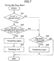
- FIG. 7 is a flowchart of a processing routine for causing the vehicle control system to control the engine 2 and the roof actuator 10, in the situation where the engine 2 is in the idle-stop state, and the vehicle 1 is in the stopped state
- FIG. 8 is a flowchart of a processing routine for causing the vehicle control system to control the engine 2 and the roof actuator 10, in the situation where the engine 2 is in the operating state. That is, after the ignition switch of the vehicle 1 is turned on, and electric power is applied to the vehicle control system, the processing routine in FIG. 7 is repeatedly executed during the idle-stop state of the engine 2, and the processing routine in FIG. 8 is repeatedly executed during the operating state of the engine 2.
- steps S23 to 26 in FIG. 7 are the same as the steps S2 to S5 in FIG. 3
- steps S33 to 36 in FIG. 8 are the same as the steps S12 to S15 in FIG. 4 .
- detailed description thereof will be omitted.
- step S21 upon start of the processing routine to control the roof actuator 10 and the engine 2 in the situation where the vehicle 1 is in the stopped state and the engine 2 is in the idle-stop state, in step S21, the control unit 25 operates to determine whether or not the roof unit 4 is in the opened state.
- step S22 the control unit 25 operates to determine whether or not the roof opening-closing button 12 has accepted the closing manipulation for shifting the roof unit 4 from the opened state to the closed state.
- step S23 the control unit 25 operates to control the engine 2 such that the engine 2 being in the idle-stop state is restarted.
- step S21 when the roof unit 4 is determined not to be in the opened state (determined to be in the closed state) or, in the step S22, when the roof opening-closing button 12 is determined not to have accepted the closing manipulation for the roof unit 4, the processing routine proceeds to step S25 in which the control unit 25 operates to determine whether or not the restart condition for restarting the engine 2 being in the idle-stop state has been satisfied.
- step S31 upon start of the processing routine to control the roof actuator 10 and the engine 2 in the situation where the engine 2 is in the operating state, in step S31, the control unit 25 operates to determine whether or not the roof unit 4 is in the opened state.
- step S32 the control unit 25 determines whether or not the vehicle speed is equal to or less than the first vehicle speed (e.g., 5 to 20 km/h) which is the upper limit of the vehicle speed range in which the opening-closing drive of the roof unit 4 is permitted, and the roof opening-closing button 12 has accepted the closing manipulation for shifting the roof unit 4 from the opened state to the closed state.
- the first vehicle speed e.g., 5 to 20 km/h
- step S33 the control unit 25 operates to operate the roof actuator 10 such that the roof unit 4 is driven from the opened state to the closed state, according to the closing manipulation accepted by the roof opening-closing button 12 in the step S32.
- step S31 when the roof unit 4 is determined not to be in the opened state (determined to be in the closed state), or, in the step S32, when it is determined that the vehicle speed is not equal to or less than the first vehicle speed (is greater than the first vehicle speed), or the roof opening-closing button 12 has not accepted the closing manipulation for the roof unit 4, the processing routine proceeds to step S35 in which the control unit 25 operates to determine whether or not the automatic idle-stop condition for automatically shifting the engine 2 being in the operating state to the idle-stop state has been satisfied.
- the present invention can be applied to any type of roof unit such as a sliding sun roof or a convertible soft top, as long as it is selectively openable and closable.
- the above embodiment has been described based on one example in which, when the roof opening-closing button 12 accepts one of the opening and closing manipulations for the roof unit 4, in the situation where the engine 2 is in the idle-stop state, and the vehicle 1 is in the stopped state, the control unit 25 operates to restart the engine 2 being in the idle-stop state, and operate the roof actuator 10.
- the control unit 25 may be configured to be operable, when the roof opening-closing button 12 accepts one of the opening and closing manipulations for the roof unit 4, in a situation where the engine 2 is in the idle-stop state, and the vehicle 1 is in a non-stopped state (i.e., vehicle speed > 0), to controllably restart the engine 2 and operate the roof actuator 10.
- the above embodiment has been described based on one example in which the determination as to whether or not the automatic idle-stop condition for automatically shifting the engine 2 to the idle-stop state has been satisfied is not performed during the period during which the roof actuator 10 drives the roof unit 4 after the roof opening-closing button 12 accepts one of the opening and closing manipulations in the situation where the engine 2 is in the operating state, so that the idle-stop operation of the engine 2 is inhibited.
- the control unit 25 may be configured to inhibit the idle-stop operation of the engine 2 in at least part of the period during which the roof actuator 10 drives the roof unit 4.
- the above embodiment has been described based on one example in which the determination as to whether or not the automatic idle-stop condition for automatically shifting the engine 2 to the idle-stop state has been satisfied is not performed during the period during which the roof actuator 10 drives the roof unit 4 after the roof opening-closing button 12 accepts one of the opening and closing manipulations in the situation where the engine 2 is in the operating state, so that the idle-stop operation of the engine 2 is inhibited.
- the idle-stop operation of the engine 2 may be inhibited by more strictly setting the automatic idle-stop condition, during the period during which the roof actuator 10 drives the roof unit 4 after the roof opening-closing button 12 accepts one of the opening and closing manipulations in the situation where the engine 2 is in the operating state.
- the automatic idle-stop condition during the period during which the roof actuator 10 drives the roof unit 4 after the roof opening-closing button 12 accepts one of the opening and closing manipulations may be strictly set such that: the upper limit of the vehicle speed is 3 km/h; the upper limit of the relative accelerator position is 2%; and the upper limit of the clutch stroke is 10%.
- control of the engine 2 and the roof actuator 10 described in the above embodiment i.e., the control of, when the roof opening and closing button 12 accepts one of the opening and closing manipulations for the roof unit 4, in the situation where the engine 2 is in the idle-stop state and the vehicle 1 is in the stopped state, restarting the engine 2 being in the idle-stop state, and operating the roof actuator 10, and, when the roof opening and closing button accepts one of the opening and closing manipulations for the roof actuator 10, inhibiting the idle-stop operation of the engine 2, during the period during which the roof actuator 10 drives the roof unit 4 after the roof opening-closing button 12 accepts one of the opening and closing manipulations) may be performed in a situation where the air conditioner 34 is in a deactivated state and in an environment in which there would be a strong need to activate the air conditioner 34.
- control unit 25 is operable, when the roof opening-closing button 12 accepts the closing manipulation for shifting the roof unit 4 from the opened state to the closed state, in the situation where the roof unit 4 is in the opened state and the engine 2 is in the idle-stop state, to control the engine 2 such that the engine 2 being in the idle-stop state is restarted, and controls the roof actuator 10 such that the roof unit 4 being in the opened state is shifted to the closed state.
- the engine 2 when, in the situation where the engine 2 is in the idle-stop state, a driver performs the closing manipulation for the roof unit 4 so as to enjoy comfortable driving under the condition that the roof unit 4 is in the closed state and the air conditioner 34 is operated, the engine 2 can be restarted in response to the closing manipulation, and then when, after the roof unit 4 is consequently set to the closed state, the driver manipulates the air-conditioning switch 24 so as to turn on the air conditioner 34, the engine speed can be rapidly increased in response to the request from the air conditioner 34 to increase the driving force of the engine 2. That is, it is possible to meet the expectation of the driver who intends adjustment of the inside temperature of the passenger compartment by the air conditioner 34.
- control unit 25 is operable, when the roof opening-closing button 12 accepts the closing manipulation for shifting the roof unit 4 from the opened state to the closed state, in the situation where the roof unit 4 is in the opened state and the engine 2 is in the operating state, to control the roof actuator 10 such that the roof unit 4 being in the opened state is shifted to the closed state, and inhibit the idle-stop operation of the engine 2, during the period during which the roof actuator 10 drives the roof unit 4 toward the closed state after the roof opening-closing button 12 accepts the closing manipulation.
- the idle-stop operation can be inhibited to maintain the operating state of the engine 2, and then when, after the roof unit 4 is consequently set to the closed state, the driver manipulates the air-conditioning switch 24 so as to turn on the air conditioner 34, the engine speed can be rapidly increased in response to the request from the air conditioner 34 to increase the driving force of the engine 2. That is, it is possible to meet the expectation of the driver who intends adjustment of the inside temperature of the passenger compartment by the air conditioner 34.
Landscapes
- Engineering & Computer Science (AREA)
- Mechanical Engineering (AREA)
- Chemical & Material Sciences (AREA)
- Combustion & Propulsion (AREA)
- General Engineering & Computer Science (AREA)
- Control Of Vehicle Engines Or Engines For Specific Uses (AREA)
- Air-Conditioning For Vehicles (AREA)
- Combined Controls Of Internal Combustion Engines (AREA)
Description
- The present invention relates to a vehicle control system, and more particularly to a vehicle control system for a vehicle equipped with: a roof unit configured to cover a top of a passenger compartment and to be selectively openable and closable; a driving device to perform opening-closing drive of the roof unit; and an engine capable of an idle-stop operation.
- Heretofore, there has been known a vehicle equipped with a roof unit configured to cover a top of a passenger compartment and to be selectively openable and closable (see, for example, the following
Patent Documents 1 and 2). The vehicle described in thePatent Document 1 is provided with an electric motor for driving an opening-closing mechanism of the roof unit, wherein the electric motor is operated according to an opening-closing manipulation of a passenger to selectively open and close the roof unit. - Further, an idle-stop technique for automatically stopping an engine of a vehicle in response to satisfaction of a given idle-stop condition has been recently employed to improve fuel economy of the vehicle, and it is studied to mount an engine capable of an idle-stop operation, on a vehicle equipped with the above openable-closable roof unit as well.
-
- Patent Document 1:
JP 2016-150587A - Patent Document 2:
US 2015/273982 A1 - Meanwhile, as one example of a usage mode of the vehicle equipped with the openable-closable roof unit as described in the
Patent Document 1, a situation is conceivable in which, after driving the vehicle while setting the roof unit in an opened state, under midsummer blazing sun, a driver shifts the roof unit to a closed state and activates an air conditioner to enjoy comfortable driving. - However, if an idle-stop state of the engine is maintained during drive of the roof unit from the closed state to the opened state, the air conditioner is likely to be unable to be activated unless the engine is first restarted, when the driver attempts to activate the air conditioner after termination of the drive of the roof unit, so that there is a possibility of failing to sufficiently meet the expectation of the driver who intends adjustment of the inside temperature of a passenger compartment of the vehicle by the air conditioner.
- The present invention has been made to solve such a problem, and an object thereof is to provide a vehicle control system for a vehicle equipped with an openable-closable roof unit and an engine capable of an idle-stop operation, wherein the vehicle control system is capable of controlling the roof unit and the engine while reflecting driver's intention.
- In order to achieve the above object, according to a first aspect of the present invention, there is provided a vehicle control system for a vehicle equipped with: a roof unit configured to cover a top of a passenger compartment and to be selectively openable and closable; a driving device to perform opening-closing drive of the roof unit; an engine capable of an idle-stop operation; and an air-conditioning device. The vehicle control system comprises: an opening-closing manipulator provided inside the passenger compartment and configured to accept opening and closing manipulations for the roof unit; and a controller configured to control the engine, the driving device, and the air-conditioning device, wherein the controller is operable, when the opening-closing manipulator accepts the closing manipulation for shifting the roof unit from an opened state to a closed state, in a situation where the roof unit is in the opened state, and the engine is in an idle-stop state, to control the engine such that the engine being in the idle-stop state is restarted, and control the driving device such that the roof unit being in the opened state is shifted to the closed state.
- In the vehicle control system according the first aspect of the present invention having the above feature, the controller is operable, when the opening-closing manipulator accepts the closing manipulation for shifting the roof unit from the opened state to the closed state, in the situation where the roof unit is in the opened state and the engine is in the idle-stop state, to control the engine such that the engine being in the idle-stop state is restarted, and controls the driving device such that the roof unit being in the opened state is shifted to the closed state. Thus, when, in the situation where the engine is in the idle-stop state, a driver performs the closing manipulation for the roof unit so as to enjoy comfortable driving under the condition that the roof unit is in the closed state and the air-conditioning device is operated, the engine can be restarted in response to the closing manipulation, and then when, after the roof unit is consequently set to the closed state, the driver manipulates an air-conditioning switch so as to turn on the air-conditioning device, an engine speed of the engine can be rapidly increased in response to a request from the air-conditioning device to increase a driving force of the engine. That is, it is possible to meet the expectation of the driver who intends adjustment of the inside temperature of the passenger compartment by the air-conditioning device.
- Preferably, in the vehicle control system according the first aspect of the present invention, the control unit is operable, when the opening-closing manipulator accepts the closing manipulation, in a situation where the roof unit is in the opened state, and the engine and the vehicle are, respectively, in the idle-stop state and in a stopped state, to control the engine such that the engine being in the idle-stop state is restarted, and control the driving device such that the roof unit being in the opened state is shifted to the closed state.
- According to this feature, particularly when the driver performs the closing manipulation for the roof unit, in the situation where the engine and the vehicle are, respectively, in the idle-stop state and in the stopped state, the engine can be restarted in response to the closing manipulation, and then when, after the roof unit is consequently set to the closed state, the driver manipulates the air-conditioning switch so as to turn on the air-conditioning device, the engine speed can be rapidly increased in response to the request from the air-conditioning device to increase the driving force of the engine. That is, it is possible to meet the expectation of the driver who intends adjustment of the inside temperature of the passenger compartment by the air-conditioning device.
- Preferably, in the vehicle control system according the first aspect of the present invention, the controller is operable to control the driving device such that the drive of the roof unit is started after the restart of the engine.
- According to this feature, when, in the situation where the engine is in the idle-stop state, the driver performs the closing manipulation for the roof unit so as to enjoy comfortable driving under the condition that the roof unit is in the closed state and the air-conditioning device is operated, the engine is first restarted in response to the closing manipulation, and subsequently the roof unit is driven. This makes it possible to produce a vehicle response fulfilling the expectation of the driver who intends adjustment of the inside temperature of the passenger compartment by the air-conditioning device.
- According to a second aspect of the present invention, there is provided a vehicle control system for a vehicle equipped with: a roof unit configured to cover a top of a passenger compartment and to be selectively openable and closable; a driving device to perform opening-closing drive of the roof unit; an engine capable of an idle-stop operation; and an air-conditioning device. The vehicle control system comprises: an opening-closing manipulator provided inside the passenger compartment and configured to accept opening and closing manipulations for the roof unit; and a controller configured to control the engine, the driving device, and the air-conditioning device, wherein the controller is operable, when the opening and closing manipulator accepts the closing manipulation for shifting the roof unit from an opened state to a closed state, in a situation where the roof unit is in the opened state, and the engine is in an operating state, to control the driving device such that the roof unit being in the opened state is shifted to the closed state, and inhibit the idle-stop operation of the engine, during a period during which the driving device drives the roof unit toward the closed state after the opening-closing manipulator accepts the closing manipulation.
- In the vehicle control system according the second aspect of the present invention having the above feature, the controller is operable, when the opening-closing manipulator accepts the closing manipulation for shifting the roof unit from the opened state to the closed state, in the situation where the roof unit is in the opened state and the engine is in the operating state, to control the driving device such that the roof unit being in the opened state is shifted to the closed state, and inhibit the idle-stop operation of the engine, during the period during which the driving device drives the roof unit toward the closed state after the opening-closing manipulator accepts the closing manipulation. Thus, when, in the situation where the engine is in the operating state, a driver performs the closing manipulation for the roof unit so as to enjoy comfortable driving under the condition that the roof unit is in the closed state and the air-conditioning device is operated, the idle-stop operation can be inhibited to maintain the operating state of the engine, and then when, after the roof unit is consequently set to the closed state, the driver manipulates an air-conditioning switch so as to turn on the air-conditioning device, an engine speed of the engine can be rapidly increased in response to a request from the air-conditioning device to increase a driving force of the engine. That is, it is possible to meet the expectation of the driver who intends adjustment of the inside temperature of the passenger compartment by the air-conditioning device.
- Preferably, in the vehicle control system according the second aspect of the present invention, the controller is operable, when a vehicle speed of the vehicle is equal to or less than a first vehicle speed, to permit the opening-closing drive of the roof unit by the driving device, and, when the vehicle speed is equal to or less than a second vehicle speed less than the first vehicle speed, to permit the idle-stop operation of the engine.
- In this case, in the conventional vehicle control system, there is a possibility that, when the vehicle speed becomes equal to or less than the first vehicle speed, the drive of the roof unit is started, and, when the vehicle speed becomes equal to or less than the second vehicle speed, the idle-stop operation of the engine is permitted. However, in the vehicle control system according the second aspect of the present invention, the controller operates to inhibit the idle-stop operation of the engine during the period during which the driving device drives the roof unit toward the opened state after the opening-closing manipulator accepts the closing manipulation. Thus, when, in the situation where the engine is in the operating state, the driver performs the closing manipulation for the roof unit so as to enjoy comfortable driving under the condition that the roof unit is in the closed state and the air-conditioning device is operated, the idle-stop operation can be inhibited to maintain the operating state of the engine, and then when, after the roof unit is consequently set to the closed state, the driver manipulates the air-conditioning switch so as to turn on the air-conditioning device, the engine speed can be rapidly increased in response to the request from the air-conditioning device to increase the driving force of the engine.
- Preferably, in the vehicle control system according the second aspect of the present invention, a drive time period required for the driving device to shift the roof unit from the opened state to the closed state is greater than a time period required for shifting the engine being in the operating state to the idle-stop state.
- In this case, in the conventional vehicle control system, there is a possibility that the idle-stop operation of the engine is started in the middle of the drive of the roof unit from the opened state to the closed state. However, in the vehicle control system according the second aspect of the present invention, the controller operates to inhibit the idle-stop operation of the engine during the period during which the driving device drives the roof unit toward the closed state after the opening-closing manipulator accepts the closing manipulation. Thus, when, in the situation where the engine is in the operating state, the driver performs the closing manipulation for the roof unit so as to enjoy comfortable driving under the condition that the roof unit is in the closed state and the air-conditioning device is operated, the idle-stop operation can be inhibited to maintain the operating state of the engine, and then when, after the roof unit is consequently set to the closed state, the driver manipulates the air-conditioning switch so as to turn on the air-conditioning device, the engine speed can be rapidly increased in response to the request from the air-conditioning device to increase the driving force of the engine.
- Preferably, in the vehicle control system according the first or second aspect of the present invention, the controller is operable to perform the control of the driving device and the engine, when the opening and closing manipulator accepts the closing manipulation for shifting the roof unit from the opened state to the closed state, in a situation where an outside temperature-related value related to an outside temperature is equal to or greater than a first threshold.
- According to this feature, particularly in an environment in which the outside temperature is relatively high and thus there is a strong need to activate the air-conditioning device, when the driver performs the closing manipulation for the roof unit, in the situation where the engine is in the idle-stop state and the vehicle is in the stopped state, the engine is restarted in response to the closing manipulation, and, when the driver performs the closing manipulation for the roof unit, in the situation where the engine is in the operating state, the idle-stop operation is inhibited to maintain the operating state of the engine. Thus, when, after the roof unit is consequently set to the closed state, the driver manipulates the air-conditioning switch so as to turn on the air-conditioning device, the engine speed can be rapidly increased in response to the request from the air-conditioning device to increase the driving force of the engine. That is, it is possible to meet the expectation of the driver who intends adjustment of the inside temperature of the passenger compartment by the air-conditioning device.
- Preferably, in the vehicle control system according the first or second aspect of the present invention, the controller is operable to perform the control of the driving device and the engine, when the opening and closing manipulator accepts the closing manipulation for shifting the roof unit from the opened state to the closed state, in a situation where an outside temperature-related value related to an outside temperature is equal to or less than a second threshold.
- According to this feature, particularly in an environment in which the outside temperature is relatively low and thus there is a strong need to activate the air-conditioning device, when the driver performs the closing manipulation for the roof unit, in the situation where the engine is in the idle-stop state and the vehicle is in the stopped state, the engine is restarted in response to the closing manipulation, and, when the driver performs the closing manipulation for the roof unit, in the situation where the engine is in the operating state, the idle-stop operation is inhibited to maintain the operating state of the engine. Thus, when, after the roof unit is consequently set to the closed state, the driver manipulates the air-conditioning switch so as to turn on the air-conditioning device, the engine speed can be rapidly increased in response to the request from the air-conditioning device to increase the driving force of the engine. That is, it is possible to meet the expectation of the driver who intends adjustment of the inside temperature of the passenger compartment by the air-conditioning device.
- Preferably, in the vehicle control system according the first or second aspect of the present invention, the controller is operable to perform the control of the driving device and the engine, when the opening and closing manipulator accepts the closing manipulation for shifting the roof unit from the opened state to the closed state, in a situation where the air-conditioning device is in a deactivated state.
- According to this feature, in an environment in which it is highly necessary to activate the air-conditioning device, when the driver performs the closing manipulation for the roof unit, in the situation where the air-conditioning device is in the deactivated state, and the engine and the vehicle are, respectively, in the idle-stop state and in the stopped state, the engine is restarted in response to the closing manipulation, and, when the driver performs the closing manipulation for the roof unit, in the situation where the air-conditioning device is in the deactivated state and the engine is in the operating state, the idle-stop operation is inhibited to maintain the operating state of the engine. Thus, when, after the roof unit is consequently set to the closed state, the driver manipulates the air-conditioning switch so as to turn on the air-conditioning device, the engine speed can be rapidly increased in response to the request from the air-conditioning device to increase the driving force of the engine. That is, it is possible to meet the expectation of the driver who intends adjustment of the inside temperature of the passenger compartment by the air-conditioning device.
- The present invention can provide a vehicle control system for a vehicle equipped with an openable-closable roof unit and an engine capable of an idle-stop operation, wherein the vehicle control system is capable of controlling the roof unit and the engine while reflecting driver's intention.
-
-
FIG. 1 is a schematic diagram depicting the entire configuration of a vehicle equipped with a vehicle control system according to one embodiment of the present invention. -
FIG. 2 is a block diagram depicting an electrical configuration of the vehicle control system according to this embodiment. -
FIG. 3 is a flowchart of a processing routine for causing the vehicle control system according to this embodiment to control an engine and a roof actuator of a roof unit. -
FIG. 4 is a flowchart of a processing routine for causing the vehicle control system according to this embodiment to control the engine and the roof actuator. -
FIG. 5 is a time chart depicting operations of the engine and the roof unit when the vehicle control system according to this embodiment controls the engine and the roof actuator. -
FIG. 6 is a time chart depicting operations of the engine and the roof unit when the vehicle control system according to this embodiment controls the engine and the roof actuator. -
FIG. 7 is a flowchart of a processing routine for causing a vehicle control system according to a modification of this embodiment to control the engine and the roof actuator. -
FIG. 8 is a flowchart of a processing routine for causing the vehicle control system according to the modification of this embodiment to control the engine and the roof actuator. - With reference to the accompanying drawings, a vehicle control system according to one embodiment of the present invention will now be described.
- First of all, a vehicle equipped with the vehicle control system according to this embodiment will be described with reference to
FIG. 1. FIG. 1 is a schematic diagram depicting the entire configuration of the vehicle equipped with the vehicle control system according to this embodiment. - In
FIG. 1 , thereference sign 1 denotes the vehicle equipped with the vehicle control system according to this embodiment. Thevehicle 1 is equipped with anengine 2 mounted on a front part of a vehicle body thereof. Theengine 2 is an internal combustion engine such as a gasoline engine or a diesel engine. - The
engine 2 has a crankshaft to which a compressor (not depicted) for an air conditioner is coupled via a pulley, a belt and the like. During a cooling operation of the air conditioner, the compressor is driven by theengine 2. - Further, a heater core of the air conditioner is connected to a water-cooling system of the
engine 2. During a heating operation of the air conditioner, cooling water heated by theengine 2 in an operating state flows into the heater core to conduct heat exchange with air inside a passenger compartment of thevehicle 1. - That is, in order to activate the air conditioner, it is necessary that the
engine 2 is in the operating state, during the cooling and heating operations. - The
vehicle 1 is also equipped with aroof unit 4 configured to cover a top of the passenger compartment and to be selectively openable and closable, and aroof storage compartment 6 for storing therein theroof unit 4 in an opened state. InFIG. 1 , theroof unit 4 in the opened state is indicated by the broken line, and theroof unit 4 in a closed state is indicated by the one-dot chain line. - The
roof unit 4 comprises a foldable roof (canvas top) 8, and a non-depicted link mechanism coupled to a rear part of the vehicle body and supporting theroof 8 in an openable-closable (foldable-unfoldable) manner. In the closed state, theroof 8 is unfolded or extended by the link mechanism to cover the top of the passenger compartment from therebehind. On the other hand, in the opened state, theroof 8 is folded by the link mechanism and retracted in theroof storage compartment 6. The link mechanism is configured to be driven by a roof actuator 10 (driving device) provided in the rear part of the vehicle body. As a drive source for theroof actuator 10, it is possible to use, e.g., a motor or an oil-hydraulic piston. - Further, the
vehicle 1 is equipped with a roof opening-closing button 12 (opening-closing manipulator) provided inside the passenger compartment at a position allowing the roof opening-closing button 12 to be manipulated by a driver and configured to accept opening and closing manipulations for theroof unit 4. The roof opening-closing button 12 is operable, in response to accepting a manual input, i.e., one of the opening and closing manipulation, to output a detection value corresponding to the manual input to the after-mentionedcontrol unit 25. - Next, an electrical configuration of the vehicle control system according to this embodiment will be described with reference to
FIG. 2. FIG. 2 is a block diagram depicting the electrical configuration of the vehicle control system according to this embodiment. - The
vehicle 1 is further equipped with: anaccelerator position sensor 14 operable to detect a relative position of an accelerator pedal (relative accelerator position); a brakedepression amount sensor 16 operable to detect the amount of depression of a brake pedal; avehicle speed sensor 18 operable to detect a vehicle speed of thevehicle 1; aclutch pedal sensor 20 operable to detect manipulation of a clutch pedal; agear sensor 22 operable to detect a gear stage of a transmission; and anair conditioner switch 24 operable to accept a manual input with respect to anair conditioner 34. Each of the sensors and the switch is operable to output a detection value thereof to acontrol unit 25. - The
control unit 25 is composed of a computer which comprises a CPU, a memory storing therein various programs, and an input-output device. Thecontrol unit 25 is operable, based on signals input from the above sensors and switch, to control theroof actuator 10, various components (astarter motor 26, afuel injector 28, aspark plug 30, etc.), of theengine 2, adisplay device 32 provided inside the vehicle compartment, and theair conditioner 34. - The
control unit 25 is equivalent to a part of "vehicle control system" as set forth in the appended claims, and functions as "controller" as set forth in the appended claims. - Next, with reference to
FIGS. 3 and 4 , an engine control processing routine to be executed by the vehicle control system according to this embodiment will be described. -
FIG. 3 is a flowchart of a processing routine for causing the vehicle control system to control theroof actuator 10 and theengine 2 in a situation where theengine 2 is in an idle-stop state, and thevehicle 1 is in a stopped state, andFIG. 4 is a flowchart of a processing routine for causing the vehicle control system to control theroof actuator 10 and theengine 2 in a situation where theengine 2 is in the operating state. That is, after an ignition switch of thevehicle 1 is turned on, and electric power is applied to the vehicle control system, the processing routine inFIG. 3 is repeatedly executed during the idle-stop state of theengine 2, and the processing routine inFIG. 4 is repeatedly executed during the operating state of theengine 2. - Firstly, as depicted in
FIG. 3 , upon start of the processing routine to control theroof actuator 10 and theengine 2 in the situation where thevehicle 1 is in the stopped state and theengine 2 is in the idle-stop state, in step S1, thecontrol unit 25 operates to determine whether or not the roof opening-closing button 12 has accepted one of the opening and closing manipulations for theroof unit 4. - As a result, when the roof opening-
closing button 12 is determined to have accepted one of the opening and closing manipulations for theroof unit 4, the processing routine proceeds to step S2 in which thecontrol unit 25 operates to control theengine 2 such that theengine 2 being in the idle-stop state is restarted. For example, thecontrol unit 25 operates to activate thestarter motor 26 to crank theengine 2 and to activate thefuel injector 28 at a given timing to inject a given amount of fuel into a cylinder of theengine 2, and cause thespark plug 30 to spark at a given timing to ignite an air-fuel mixture in the cylinder, thereby restarting theengine 2. - Subsequently, the processing routine proceeds to step S3 in which the
control unit 25 operates to operate theroof actuator 10 such that theroof unit 4 is driven from the closed state to the opened state, or from the opened state to the closed state, depending on one of the opening and closing manipulations accepted by the roof opening-closing button 12 in the step S1. After completion of the operation of theroof actuator 10, the processing of thecontrol unit 25 is terminated. - On the other hand, in the step S1, when the roof opening-
closing button 12 is determined not to have accepted any of the opening and closing manipulations for theroof unit 4, the processing routine proceeds to step S4 in which thecontrol unit 25 operates to determine whether or not a restart condition for restarting theengine 2 being in the idle-stop state has been satisfied. - For example, the
control unit 25 may be configured to acquire a depressed state of the clutch pedal based on a signal input from theclutch pedal sensor 20. In this case, in response to detecting that the clutch pedal has been depressed, thecontrol unit 25 operates to determine that the restart condition has been satisfied. - As a result of the determination in the step S4, when the restart condition is determined to have been satisfied, the processing routine proceeds to step S5 in which the
control unit 25 operates to control theengine 2 such that theengine 2 being in the idle-stop state is restarted. After restart of theengine 2, or, in the step S4, when the restart condition is determined not to have been satisfied, the processing of thecontrol unit 25 is terminated. - Secondly, as depicted in
FIG. 4 , upon start of the processing routine to control theroof actuator 10 and theengine 2 in the situation where theengine 2 is in the operating state, in step S11, thecontrol unit 25 operates to determine whether or not the vehicle speed is equal to or less than a first vehicle speed (e.g., 5 to 20 km/h) which is an upper limit of a vehicle speed range in which opening-closing drive of theroof unit 4 is permitted, and the roof opening-closing button 12 has accepted one of the opening and closing manipulations for theroof unit 4. - As a result, when it is determined that the vehicle speed is equal to or less than the first vehicle speed, and the roof opening-
closing button 12 has accepted one of the opening and closing manipulations for theroof unit 4, the processing routine proceeds to step S12 in which thecontrol unit 25 operates to operate theroof actuator 10 such that theroof unit 4 is driven from the closed state to the opened state, or from the opened state to the closed state, depending on one of the opening and closing manipulations accepted by the roof opening-closing button 12 in the step S11. - Subsequently, in step S13, the
control unit 25 operates to determine whether or not the operation of the roof actuator has been completed. As a result, when the operation of theroof actuator 10 is determined not to have been completed, thecontrol unit 25 operates to wait until the operation of theroof actuator 10 is completed. Then, after completion of the operation of theroof actuator 10, the processing of thecontrol unit 25 is terminated. - On the other hand, in the step S11, when it is determined that the vehicle speed is not equal to or less than the first vehicle speed (is greater than the first vehicle speed), or the roof opening-
closing button 12 has not accepted any of the opening and closing manipulations for theroof unit 4, the processing routine proceeds to step S14 in which thecontrol unit 25 operates to determine whether or not an automatic idle-stop condition for automatically shifting theengine 2 being in the operating state to the idle-stop state has been satisfied. - For example, when: the vehicle speed detected by the
vehicle speed sensor 18 is equal to or less than a second vehicle speed (e.g., 3 to 5 km/h) less than the first vehicle speed; the relative accelerator position detected by theaccelerator position sensor 14 is equal to or less than 3%; the gear stage detected by thegear sensor 22 is a neutral stage; and a clutch stroke (depressed state) detected theclutch pedal sensor 20 is less than 20%, thecontrol unit 25 operates to determine that the automatic idle-stop condition has been satisfied. - As a result of the determination in the step S14, the automatic idle-stop condition is determined to have been satisfied, the processing routine proceeds to step S15 in which the
control unit 25 operates to control theengine 2 such that theengine 2 being in the operating state is shifted to the idle-stop state. After shifting theengine 2 to the idle-stop state, or, in the step S14, when the automatic idle-stop condition is determined not to have been satisfied, the processing of thecontrol unit 25 is terminated. - Next, respective operations of the
engine 2 and theroof unit 4 when the vehicle control system according to this embodiment controls theengine 2 and theroof actuator 10 will be described with reference toFIGS. 5 and 6 . -
FIG. 5 is a time chart depicting respective operations of theengine 2 and theroof unit 4 when the vehicle control system controls theengine 2 and theroof actuator 10 in the situation where thevehicle 1 is in the stopped state and theengine 2 is in the idle-stop state, andFIG. 6 is a time chart depicting respective operations of theengine 2 and theroof unit 4 when the vehicle control system according to this embodiment controls theengine 2 and theroof actuator 10 in the situation where theengine 2 is in the operating state. - As depicted in
FIG. 5 , when the roof opening-closing button 12 accepts, at time T1, the closing manipulation for shifting theroof unit 4 from the opened state to the closed state, in the situation where thevehicle 1 is in the stopped state and theengine 2 is in the idle-stop state, thecontrol unit 25 operates to control theengine 2 such that theengine 2 being in the idle-stop state is restarted. - When the engine speed of the restarted
engine 2 reaches an idle speed at time T2, thecontrol unit 25 operates to operate theroof actuator 10 such that theroof unit 4 is driven from the opened state to the closed state, according to the closing manipulation accepted by the roof opening-closing button 12. - Subsequently, when a driver manipulates the air-
conditioning switch 24 so as to turn on theair conditioner 34, the engine speed is rapidly increased in response to a request from theair conditioner 34 to increase a driving force of theengine 2, because theengine 2 has already been restarted and the engine speed thereof has reached the idle speed. That is, it is possible to meet the expectation of the driver who intends adjustment of the inside temperature of the passenger compartment by theair conditioner 34. - On the other hand, differently from the vehicle control system according to this embodiment, if the
control unit 25 does not operate to restart theengine 2 being in the idle-stop state, when the roof opening-closing button 12 accepts the closing manipulation, theengine 2 is maintained in the idle-stop state until the restart condition is satisfied at the time T3, as indicated by the one-dot chain line inFIG. 5 . Thus, when a driver manipulates, at the time T3, the air-conditioning switch 24 so as to turn on theair conditioner 34, theengine 2 being in the idle-stop state has to be first restarted, so that it is impossible to sufficiently meet the expectation of the driver who intends adjustment of the inside temperature of the passenger compartment by theair conditioner 34. - Further, as depicted in
FIG. 6 , when the roof opening-closing button 12 accepts, at time T4, the closing manipulation for shifting theroof unit 4 from the opened state to the closed state, in the situation where theengine 2 is in the operating state, thecontrol unit 25 operates to operate theroof actuator 10 such that theroof unit 4 is driven from the opened state to the closed state, according to the closing manipulation accepted by the roof opening-closing button 12. - A time period required for the
roof actuator 10 to shift theroof unit 4 from the opened state to the closed state is about 10 to 20 seconds, which is greater than a time period (less than one second) required for shifting theengine 2 being in the operating state to the idle-stop state. Thus, in the conventional vehicle control system, when the automatic idle-stop condition for automatically shifting theengine 2 to the idle-stop state is satisfied in the middle of movement of theroof unit 4, theengine 2 is likely to be shifted to the idle-stop state in the middle of the movement of theroof unit 4. - However, in the vehicle control system according to this embodiment, the determination as to whether or not the automatic idle-stop condition for automatically shifting the
engine 2 to the idle-stop state has been satisfied is not performed during a period during which theroof actuator 10 drives theroof unit 4 toward the closed state after the roof opening-closing button 12 accepts the closing manipulation (seeFIG. 4 ), so that, even if the automatic idle-stop condition is satisfied at, e.g., time T5, an idle-stop operation of theengine 2 is inhibited. - Subsequently, when the driver manipulates, at time T6, an air-
conditioning switch 24 so as to turn on theair conditioner 34, the engine speed is rapidly increased in response to the request from theair conditioner 34 to increase the driving force of theengine 2, because the idle-stop operation of theengine 2 is inhibited to maintain the idle speed. That is, it is possible to meet the expectation of the driver who intends adjustment of the inside temperature of the passenger compartment by theair conditioner 34. - On the other hand, differently from the vehicle control system according to this embodiment, if the
control unit 25 does not operate to inhibit theengine 2 being in the operating state from being shifted to the idle-stop state, when the roof opening-closing button 12 accepts the closing manipulation, thecontrol unit 25 operates to shift theengine 2 to the idle-stop state when the automatic idle-stop condition is satisfied at, e.g., the time T5, as indicated by the one-dot chain line inFIG. 6 . Thus, when a driver manipulates, at time T6, the air-conditioning switch 24 so as to turn on theair conditioner 34, theengine 2 being in the idle-stop state has to be first restarted, so that it is impossible to sufficiently meet the expectation of the driver who intends adjustment of the inside temperature of the passenger compartment by theair conditioner 34. - Next, a vehicle control system according to a modification of the above embodiment will be described.
- The above embodiment has been described based on one example in which, when the roof opening-
closing button 12 accepts one of the opening and closing manipulations for theroof unit 4, thecontrol unit 25 operates to restart theengine 2 or inhibit the idle-stop operation of theengine 2, and cause theroof actuator 10 to drive theroof unit 4, as depicted inFIGS. 3 and 4 . Alternatively, as depicted inFIGS. 7 and8 , thecontrol unit 25 may be configured to be operable, particularly when the roof opening-closing button 12 accepts the closing manipulation for shifting theroof unit 4 from the opened state to the closed state, to restart theengine 2 or inhibit the idle-stop operation of theengine 2, and cause theroof actuator 10 to drive theroof unit 4. -
FIG. 7 is a flowchart of a processing routine for causing the vehicle control system to control theengine 2 and theroof actuator 10, in the situation where theengine 2 is in the idle-stop state, and thevehicle 1 is in the stopped state, andFIG. 8 is a flowchart of a processing routine for causing the vehicle control system to control theengine 2 and theroof actuator 10, in the situation where theengine 2 is in the operating state. That is, after the ignition switch of thevehicle 1 is turned on, and electric power is applied to the vehicle control system, the processing routine inFIG. 7 is repeatedly executed during the idle-stop state of theengine 2, and the processing routine inFIG. 8 is repeatedly executed during the operating state of theengine 2. - Here, steps S23 to 26 in
FIG. 7 are the same as the steps S2 to S5 inFIG. 3 , and steps S33 to 36 inFIG. 8 are the same as the steps S12 to S15 inFIG. 4 . Thus, detailed description thereof will be omitted. - Firstly, as depicted in
FIG. 7 , upon start of the processing routine to control theroof actuator 10 and theengine 2 in the situation where thevehicle 1 is in the stopped state and theengine 2 is in the idle-stop state, in step S21, thecontrol unit 25 operates to determine whether or not theroof unit 4 is in the opened state. - As a result, when the
roof unit 4 is determined to be in the opened state, the processing routine proceeds to step S22 in which thecontrol unit 25 operates to determine whether or not the roof opening-closing button 12 has accepted the closing manipulation for shifting theroof unit 4 from the opened state to the closed state. - As a result, when the roof opening-
closing button 12 is determined to have accepted the closing manipulation for theroof unit 4, the processing routine proceeds to step S23 in which thecontrol unit 25 operates to control theengine 2 such that theengine 2 being in the idle-stop state is restarted. - On the other hand, in the step S21, when the
roof unit 4 is determined not to be in the opened state (determined to be in the closed state) or, in the step S22, when the roof opening-closing button 12 is determined not to have accepted the closing manipulation for theroof unit 4, the processing routine proceeds to step S25 in which thecontrol unit 25 operates to determine whether or not the restart condition for restarting theengine 2 being in the idle-stop state has been satisfied. - Secondly, as depicted in
FIG. 8 , upon start of the processing routine to control theroof actuator 10 and theengine 2 in the situation where theengine 2 is in the operating state, in step S31, thecontrol unit 25 operates to determine whether or not theroof unit 4 is in the opened state. - As a result, the
roof unit 4 is determined to be in the opened state, the processing routine proceeds to step S32 in which thecontrol unit 25 determines whether or not the vehicle speed is equal to or less than the first vehicle speed (e.g., 5 to 20 km/h) which is the upper limit of the vehicle speed range in which the opening-closing drive of theroof unit 4 is permitted, and the roof opening-closing button 12 has accepted the closing manipulation for shifting theroof unit 4 from the opened state to the closed state. - As a result, when it is determined that the vehicle speed is equal to or less than the first vehicle speed, and the roof opening-
closing button 12 has accepted the closing manipulation for theroof unit 4, the processing routine proceeds to step S33 in which thecontrol unit 25 operates to operate theroof actuator 10 such that theroof unit 4 is driven from the opened state to the closed state, according to the closing manipulation accepted by the roof opening-closing button 12 in the step S32. - On the other hand, in the step S31, when the
roof unit 4 is determined not to be in the opened state (determined to be in the closed state), or, in the step S32, when it is determined that the vehicle speed is not equal to or less than the first vehicle speed (is greater than the first vehicle speed), or the roof opening-closing button 12 has not accepted the closing manipulation for theroof unit 4, the processing routine proceeds to step S35 in which thecontrol unit 25 operates to determine whether or not the automatic idle-stop condition for automatically shifting theengine 2 being in the operating state to the idle-stop state has been satisfied. - Further, although the above embodiment has been described based on one example in which the
roof unit 4 comprises thefoldable roof 8, and the non-depicted link mechanism coupled to the rear part of the vehicle body and supporting theroof 8 in an openable-closable manner, the present invention can be applied to any type of roof unit such as a sliding sun roof or a convertible soft top, as long as it is selectively openable and closable. - Further, although the above embodiment has been described based on one example in which, in
FIG. 3 , after restarting theengine 2 in the step S2, theroof actuator 10 is operated in the step S3, theengine 2 may be restarted after starting the operation of theroof actuator 10. - Further, the above embodiment has been described based on one example in which, when the roof opening-
closing button 12 accepts one of the opening and closing manipulations for theroof unit 4, in the situation where theengine 2 is in the idle-stop state, and thevehicle 1 is in the stopped state, thecontrol unit 25 operates to restart theengine 2 being in the idle-stop state, and operate theroof actuator 10. Alternatively, thecontrol unit 25 may be configured to be operable, when the roof opening-closing button 12 accepts one of the opening and closing manipulations for theroof unit 4, in a situation where theengine 2 is in the idle-stop state, and thevehicle 1 is in a non-stopped state (i.e., vehicle speed > 0), to controllably restart theengine 2 and operate theroof actuator 10. - Further, the above embodiment has been described based on one example in which the determination as to whether or not the automatic idle-stop condition for automatically shifting the
engine 2 to the idle-stop state has been satisfied is not performed during the period during which theroof actuator 10 drives theroof unit 4 after the roof opening-closing button 12 accepts one of the opening and closing manipulations in the situation where theengine 2 is in the operating state, so that the idle-stop operation of theengine 2 is inhibited. Alternatively, thecontrol unit 25 may be configured to inhibit the idle-stop operation of theengine 2 in at least part of the period during which theroof actuator 10 drives theroof unit 4. - Further, the above embodiment has been described based on one example in which the determination as to whether or not the automatic idle-stop condition for automatically shifting the
engine 2 to the idle-stop state has been satisfied is not performed during the period during which theroof actuator 10 drives theroof unit 4 after the roof opening-closing button 12 accepts one of the opening and closing manipulations in the situation where theengine 2 is in the operating state, so that the idle-stop operation of theengine 2 is inhibited. Alternatively, the idle-stop operation of theengine 2 may be inhibited by more strictly setting the automatic idle-stop condition, during the period during which theroof actuator 10 drives theroof unit 4 after the roof opening-closing button 12 accepts one of the opening and closing manipulations in the situation where theengine 2 is in the operating state. For example, in a case where the automatic idle-stop condition in a normal state is set such that: the upper limit of the vehicle speed is 5 km/h; the upper limit of the relative accelerator position is 3%; and the upper limit of the clutch stroke is 20%, the automatic idle-stop condition during the period during which theroof actuator 10 drives theroof unit 4 after the roof opening-closing button 12 accepts one of the opening and closing manipulations may be strictly set such that: the upper limit of the vehicle speed is 3 km/h; the upper limit of the relative accelerator position is 2%; and the upper limit of the clutch stroke is 10%. - Further, the control of the engine 2 and the roof actuator 10 described in the above embodiment (i.e., the control of, when the roof opening and closing button 12 accepts one of the opening and closing manipulations for the roof unit 4, in the situation where the engine 2 is in the idle-stop state and the vehicle 1 is in the stopped state, restarting the engine 2 being in the idle-stop state, and operating the roof actuator 10, and, when the roof opening and closing button accepts one of the opening and closing manipulations for the roof actuator 10, inhibiting the idle-stop operation of the engine 2, during the period during which the roof actuator 10 drives the roof unit 4 after the roof opening-closing button 12 accepts one of the opening and closing manipulations) may be performed when an outside temperature-related value (outside temperature, cooling water temperature, etc.) related to an outside temperature is equal to or greater than a first threshold (e.g., the outside temperature is equal to or greater than a temperature between 25°C and 30°C), or the outside temperature-related value is equal to or less than a second threshold (e.g., the outside temperature is equal to or less than a temperature between 5°C and 10°C), i.e., in an environment in which there would be a strong need to activate the air conditioner 34.
- Further, the control of the
engine 2 and theroof actuator 10 described in the above embodiment (i.e., the control of, when the roof opening andclosing button 12 accepts one of the opening and closing manipulations for theroof unit 4, in the situation where theengine 2 is in the idle-stop state and thevehicle 1 is in the stopped state, restarting theengine 2 being in the idle-stop state, and operating theroof actuator 10, and, when the roof opening and closing button accepts one of the opening and closing manipulations for theroof actuator 10, inhibiting the idle-stop operation of theengine 2, during the period during which theroof actuator 10 drives theroof unit 4 after the roof opening-closing button 12 accepts one of the opening and closing manipulations) may be performed in a situation where theair conditioner 34 is in a deactivated state and in an environment in which there would be a strong need to activate theair conditioner 34. - Last of all, advantageous effects of the vehicle control systems according to the above embodiment and the modification of the above embodiment will be described.
- Firstly, the
control unit 25 is operable, when the roof opening-closing button 12 accepts the closing manipulation for shifting theroof unit 4 from the opened state to the closed state, in the situation where theroof unit 4 is in the opened state and theengine 2 is in the idle-stop state, to control theengine 2 such that theengine 2 being in the idle-stop state is restarted, and controls theroof actuator 10 such that theroof unit 4 being in the opened state is shifted to the closed state. Thus, when, in the situation where theengine 2 is in the idle-stop state, a driver performs the closing manipulation for theroof unit 4 so as to enjoy comfortable driving under the condition that theroof unit 4 is in the closed state and theair conditioner 34 is operated, theengine 2 can be restarted in response to the closing manipulation, and then when, after theroof unit 4 is consequently set to the closed state, the driver manipulates the air-conditioning switch 24 so as to turn on theair conditioner 34, the engine speed can be rapidly increased in response to the request from theair conditioner 34 to increase the driving force of theengine 2. That is, it is possible to meet the expectation of the driver who intends adjustment of the inside temperature of the passenger compartment by theair conditioner 34. - Secondly, the
control unit 25 is operable, when the roof opening-closing button 12 accepts the closing manipulation for shifting theroof unit 4 from the opened state to the closed state, in the situation where theroof unit 4 is in the opened state and theengine 2 is in the operating state, to control theroof actuator 10 such that theroof unit 4 being in the opened state is shifted to the closed state, and inhibit the idle-stop operation of theengine 2, during the period during which theroof actuator 10 drives theroof unit 4 toward the closed state after the roof opening-closing button 12 accepts the closing manipulation. Thus, when, in the situation where theengine 2 is in the operating state, a driver performs the closing manipulation for theroof unit 4 so as to enjoy comfortable driving under the condition that theroof unit 4 is in the closed state and theair conditioner 34 is operated, the idle-stop operation can be inhibited to maintain the operating state of theengine 2, and then when, after theroof unit 4 is consequently set to the closed state, the driver manipulates the air-conditioning switch 24 so as to turn on theair conditioner 34, the engine speed can be rapidly increased in response to the request from theair conditioner 34 to increase the driving force of theengine 2. That is, it is possible to meet the expectation of the driver who intends adjustment of the inside temperature of the passenger compartment by theair conditioner 34. -
- 1
- vehicle
- 2
- engine
- 4
- roof unit
- 6
- roof storage compartment
- 8
- roof
- 10
- roof actuator
- 12
- roof opening-closing button
- 14
- accelerator position sensor
- 16
- brake depression amount sensor
- 18
- vehicle speed sensor
- 20
- clutch pedal sensor
- 22
- gear sensor
- 24
- air conditioner switch
- 25
- control unit
- 26
- starter motor
- 28
- fuel injector
- 30
- spark plug
- 32
- display device
- 34
- air conditioner
Claims (9)
- A vehicle control system for a vehicle equipped with: a roof unit (4) configured to cover a top of a passenger compartment and to be selectively openable and closable; a driving device (10) to perform opening-closing drive of the roof unit (4); an engine (2) capable of an idle-stop operation; and an air-conditioning device (34), the vehicle control system comprising:an opening-closing manipulator (12) provided inside the passenger compartment and configured to accept opening and closing manipulations for the roof unit (4); anda controller configured to control the engine (2), the driving device (10) and the air-conditioning device (34),characterized in that the controller is operable, when the opening-closing manipulator accepts the closing manipulation for shifting the roof unit from an opened state to a closed state, in a situation where the roof unit is in the opened state and the engine is in an idle-stop state, to control the engine such that the engine being in the idle-stop state is restarted, and control the driving device such that the roof unit being in the opened state is shifted to the closed state.
- The vehicle control system according to claim 1, wherein the control unit is operable, when the opening-closing manipulator accepts the closing manipulation, in a situation where the roof unit is in the opened state and the engine and the vehicle are in the idle-stop state and in a stopped state, respectively, to control the engine such that the engine being in the idle-stop state is restarted, and control the driving device such that the roof unit being in the opened state is shifted to the closed state.
- The vehicle control system according to claim 1 or 2, wherein the controller is operable to control the driving device such that the drive of the roof unit is started after the restart of the engine.
- A vehicle control system for a vehicle equipped with: a roof unit (4) Z configured to cover a top of a passenger compartment and to be selectively openable and closable; a driving device (10) to perform opening-closing drive of the roof unit (4); an engine (2) capable of an idle-stop operation; and an air-conditioning device (34), the vehicle control system comprising:an opening-closing manipulator (12) provided inside the passenger compartment and configured to accept opening and closing manipulations for the roof unit; anda controller (25) configured to control the engine (2), the driving device (10) and the air-conditioning device (34),characterized in that the controller is operable, when the opening and closing manipulator accepts the closing manipulation for shifting the roof unit from an opened state to a closed state, in a situation where the roof unit is in the opened state and the engine is in an operating state, to control the driving device such that the roof unit being in the opened state is shifted to the closed state, and inhibit the idle-stop operation of the engine, during a period during which the driving device drives the roof unit toward the closed state after the opening-closing manipulator accepts the closing manipulation.
- The vehicle control system according to claim 4, wherein the controller is operable, when a vehicle speed of the vehicle is equal to or less than a first vehicle speed, to permit the opening-closing drive of the roof unit by the driving device, and, when the vehicle speed is equal to or less than a second vehicle speed less than the first vehicle speed, to permit the idle-stop operation of the engine.
- The vehicle control system according to claim 4 or 5, wherein a drive time period required for the driving device to shift the roof unit from the opened state to the closed state is greater than a time period required for shifting the engine being in the operating state to the idle-stop state.
- The vehicle control system according to any one of claims 1 to 6, wherein the controller is operable to perform the control of the driving device and the engine, when the opening and closing manipulator accepts the closing manipulation for shifting the roof unit from the opened state to the closed state, in a situation where an outside temperature-related value related to an outside temperature is equal to or greater than a first threshold.
- The vehicle control system according to any one of claims 1 to 7, wherein the controller is operable to perform the control of the driving device and the engine, when the opening and closing manipulator accepts the closing manipulation for shifting the roof unit from the opened state to the closed state, in a situation where an outside temperature-related value related to an outside temperature is equal to or less than a second threshold.
- The vehicle control system according to any one of claims 1 to 8, wherein the controller is operable to perform the control of the driving device and the engine, when the opening and closing manipulator accepts the closing manipulation for shifting the roof unit from the opened state to the closed state, in a situation where the air-conditioning device is in a deactivated state.
Applications Claiming Priority (2)
| Application Number | Priority Date | Filing Date | Title |
|---|---|---|---|
| JP2016202750A JP6350976B2 (en) | 2016-10-14 | 2016-10-14 | Vehicle control device |
| PCT/JP2017/037078 WO2018070498A1 (en) | 2016-10-14 | 2017-10-12 | Vehicular control device |
Publications (3)
| Publication Number | Publication Date |
|---|---|
| EP3527806A1 EP3527806A1 (en) | 2019-08-21 |
| EP3527806A4 EP3527806A4 (en) | 2019-10-30 |
| EP3527806B1 true EP3527806B1 (en) | 2020-09-09 |
Family
ID=61905591
Family Applications (1)
| Application Number | Title | Priority Date | Filing Date |
|---|---|---|---|
| EP17860497.1A Active EP3527806B1 (en) | 2016-10-14 | 2017-10-12 | Vehicular control device |
Country Status (5)
| Country | Link |
|---|---|
| US (1) | US20200049119A1 (en) |
| EP (1) | EP3527806B1 (en) |
| JP (1) | JP6350976B2 (en) |
| CN (1) | CN109844286B (en) |
| WO (1) | WO2018070498A1 (en) |
Families Citing this family (1)
| Publication number | Priority date | Publication date | Assignee | Title |
|---|---|---|---|---|
| JP7377747B2 (en) * | 2020-03-18 | 2023-11-10 | 本田技研工業株式会社 | Vehicle control device, vehicle control method, and vehicle control program |
Family Cites Families (17)
| Publication number | Priority date | Publication date | Assignee | Title |
|---|---|---|---|---|
| JPS58149542A (en) * | 1982-03-01 | 1983-09-05 | Hitachi Ltd | Data processing device |
| JPS58169160A (en) * | 1982-03-31 | 1983-10-05 | Mita Ind Co Ltd | Developing device |
| JPS58149542U (en) * | 1982-04-01 | 1983-10-07 | トヨタ自動車株式会社 | Engine automatic stop/start device |
| JPS58169160U (en) * | 1982-05-10 | 1983-11-11 | トヨタ自動車株式会社 | Engine automatic stop/start device |
| JPS6088043A (en) * | 1983-10-21 | 1985-05-17 | Tokyo Copal Kagaku Kk | Application of surface modifier to synthetic resin molded article |
| JPS6088043U (en) * | 1983-11-24 | 1985-06-17 | 日産自動車株式会社 | Engine automatic stop/start device |
| US5018783A (en) * | 1989-09-19 | 1991-05-28 | Asc Incorporated | Slidable, foldable, and removable vehicle sunroof |
| JPH06257482A (en) * | 1993-03-06 | 1994-09-13 | Suzuki Motor Corp | Automatic engine start / stop device |
| JP2001098968A (en) * | 1999-09-30 | 2001-04-10 | Mazda Motor Corp | Vehicle control device |
| JP5640720B2 (en) * | 2010-12-16 | 2014-12-17 | アイシン精機株式会社 | Sunshade for vehicle |
| JP6040622B2 (en) * | 2012-08-10 | 2016-12-07 | マツダ株式会社 | Air conditioning control device for vehicles |
| US8838315B2 (en) * | 2012-09-18 | 2014-09-16 | Ford Global Technologies, Llc | System and method for indicating delay in implementation of an energy-expending action in a powered vehicle system |
| CN203835546U (en) * | 2013-11-19 | 2014-09-17 | 郑州日产汽车有限公司 | Multifunctional commercial vehicle automatic starting and stopping control system suitable for car platform |
| JP6172017B2 (en) * | 2014-03-27 | 2017-08-02 | マツダ株式会社 | Air conditioning control device for vehicles |
| JP6090235B2 (en) * | 2014-05-27 | 2017-03-08 | マツダ株式会社 | Air conditioning control device for vehicles |
| JP6225929B2 (en) | 2015-02-16 | 2017-11-08 | マツダ株式会社 | Rear body structure of the vehicle |
| CN105035071B (en) * | 2015-05-29 | 2017-11-17 | 武汉理工大学 | A kind of automatic control method with car system that condition of stopping work is walked towards automobile low speed under urban environment |
-
2016
- 2016-10-14 JP JP2016202750A patent/JP6350976B2/en active Active
-
2017
- 2017-10-12 CN CN201780063278.5A patent/CN109844286B/en active Active
- 2017-10-12 EP EP17860497.1A patent/EP3527806B1/en active Active
- 2017-10-12 US US16/340,767 patent/US20200049119A1/en not_active Abandoned
- 2017-10-12 WO PCT/JP2017/037078 patent/WO2018070498A1/en not_active Ceased
Non-Patent Citations (1)
| Title |
|---|
| None * |
Also Published As
| Publication number | Publication date |
|---|---|
| JP6350976B2 (en) | 2018-07-04 |
| CN109844286A (en) | 2019-06-04 |
| EP3527806A4 (en) | 2019-10-30 |
| WO2018070498A1 (en) | 2018-04-19 |
| US20200049119A1 (en) | 2020-02-13 |
| CN109844286B (en) | 2021-05-07 |
| EP3527806A1 (en) | 2019-08-21 |
| JP2018062927A (en) | 2018-04-19 |
Similar Documents
| Publication | Publication Date | Title |
|---|---|---|
| US9322378B2 (en) | Methods and systems for starting an engine of a hybrid vehicle | |
| US11421640B2 (en) | Intermittent restart for automatic engine stop start system | |
| JP2004245219A (en) | Method and apparatus for starting an internal combustion engine of a vehicle | |
| CN105781761A (en) | Control System For Vehicle | |
| US20130231850A1 (en) | Control apparatus for vehicular internal combustion engine | |
| US9103312B2 (en) | Vehicle control apparatus | |
| JP2011202533A (en) | Device for control of on-board internal combustion engine | |
| EP3527806B1 (en) | Vehicular control device | |
| JP2009002312A (en) | Vehicle control device | |
| JP2018030530A (en) | Hybrid-vehicular control apparatus | |
| JP2004308576A (en) | Engine start control device and start control method | |
| EP3524802A1 (en) | Vehicle control device | |
| JP4214812B2 (en) | Idle stop device | |
| JP2011106357A (en) | Idling stop control device for vehicle | |
| JP2014199057A (en) | Vehicle control device | |
| JP2007162939A (en) | Vehicle driving method and apparatus | |
| JP3541874B2 (en) | Vehicle engine starter | |
| JP3783663B2 (en) | Vehicle engine start control device | |
| JP6007816B2 (en) | Vehicle control device | |
| JP5811026B2 (en) | Vehicle control device | |
| JP2008121587A (en) | Engine control device | |
| JP2007077894A (en) | Control device for vehicles equipped with remote engine starter | |
| JP2013164082A (en) | Control device for vehicle-mounted internal combustion engine |
Legal Events
| Date | Code | Title | Description |
|---|---|---|---|
| STAA | Information on the status of an ep patent application or granted ep patent |
Free format text: STATUS: THE INTERNATIONAL PUBLICATION HAS BEEN MADE |
|
| PUAI | Public reference made under article 153(3) epc to a published international application that has entered the european phase |
Free format text: ORIGINAL CODE: 0009012 |
|
| STAA | Information on the status of an ep patent application or granted ep patent |
Free format text: STATUS: REQUEST FOR EXAMINATION WAS MADE |
|
| 17P | Request for examination filed |
Effective date: 20190509 |
|
| AK | Designated contracting states |
Kind code of ref document: A1 Designated state(s): AL AT BE BG CH CY CZ DE DK EE ES FI FR GB GR HR HU IE IS IT LI LT LU LV MC MK MT NL NO PL PT RO RS SE SI SK SM TR |
|
| AX | Request for extension of the european patent |
Extension state: BA ME |
|
| A4 | Supplementary search report drawn up and despatched |
Effective date: 20190930 |
|
| RIC1 | Information provided on ipc code assigned before grant |
Ipc: F02D 29/02 20060101AFI20190925BHEP Ipc: F02N 11/08 20060101ALI20190925BHEP Ipc: B60J 7/12 20060101ALI20190925BHEP Ipc: F02D 45/00 20060101ALI20190925BHEP Ipc: B60J 7/057 20060101ALI20190925BHEP |
|
| DAV | Request for validation of the european patent (deleted) | ||
| DAX | Request for extension of the european patent (deleted) | ||
| GRAP | Despatch of communication of intention to grant a patent |
Free format text: ORIGINAL CODE: EPIDOSNIGR1 |
|
| STAA | Information on the status of an ep patent application or granted ep patent |
Free format text: STATUS: GRANT OF PATENT IS INTENDED |
|
| INTG | Intention to grant announced |
Effective date: 20200420 |
|
| GRAS | Grant fee paid |
Free format text: ORIGINAL CODE: EPIDOSNIGR3 |
|
| GRAA | (expected) grant |
Free format text: ORIGINAL CODE: 0009210 |
|
| STAA | Information on the status of an ep patent application or granted ep patent |
Free format text: STATUS: THE PATENT HAS BEEN GRANTED |
|
| AK | Designated contracting states |
Kind code of ref document: B1 Designated state(s): AL AT BE BG CH CY CZ DE DK EE ES FI FR GB GR HR HU IE IS IT LI LT LU LV MC MK MT NL NO PL PT RO RS SE SI SK SM TR |
|
| REG | Reference to a national code |
Ref country code: GB Ref legal event code: FG4D |
|
| REG | Reference to a national code |
Ref country code: AT Ref legal event code: REF Ref document number: 1311866 Country of ref document: AT Kind code of ref document: T Effective date: 20200915 Ref country code: CH Ref legal event code: EP |
|
| REG | Reference to a national code |
Ref country code: IE Ref legal event code: FG4D |
|
| REG | Reference to a national code |
Ref country code: DE Ref legal event code: R096 Ref document number: 602017023543 Country of ref document: DE |
|
| REG | Reference to a national code |
Ref country code: LT Ref legal event code: MG4D |
|
| PG25 | Lapsed in a contracting state [announced via postgrant information from national office to epo] |
Ref country code: FI Free format text: LAPSE BECAUSE OF FAILURE TO SUBMIT A TRANSLATION OF THE DESCRIPTION OR TO PAY THE FEE WITHIN THE PRESCRIBED TIME-LIMIT Effective date: 20200909 Ref country code: LT Free format text: LAPSE BECAUSE OF FAILURE TO SUBMIT A TRANSLATION OF THE DESCRIPTION OR TO PAY THE FEE WITHIN THE PRESCRIBED TIME-LIMIT Effective date: 20200909 Ref country code: GR Free format text: LAPSE BECAUSE OF FAILURE TO SUBMIT A TRANSLATION OF THE DESCRIPTION OR TO PAY THE FEE WITHIN THE PRESCRIBED TIME-LIMIT Effective date: 20201210 Ref country code: BG Free format text: LAPSE BECAUSE OF FAILURE TO SUBMIT A TRANSLATION OF THE DESCRIPTION OR TO PAY THE FEE WITHIN THE PRESCRIBED TIME-LIMIT Effective date: 20201209 Ref country code: NO Free format text: LAPSE BECAUSE OF FAILURE TO SUBMIT A TRANSLATION OF THE DESCRIPTION OR TO PAY THE FEE WITHIN THE PRESCRIBED TIME-LIMIT Effective date: 20201209 Ref country code: SE Free format text: LAPSE BECAUSE OF FAILURE TO SUBMIT A TRANSLATION OF THE DESCRIPTION OR TO PAY THE FEE WITHIN THE PRESCRIBED TIME-LIMIT Effective date: 20200909 Ref country code: HR Free format text: LAPSE BECAUSE OF FAILURE TO SUBMIT A TRANSLATION OF THE DESCRIPTION OR TO PAY THE FEE WITHIN THE PRESCRIBED TIME-LIMIT Effective date: 20200909 |
|
| REG | Reference to a national code |
Ref country code: AT Ref legal event code: MK05 Ref document number: 1311866 Country of ref document: AT Kind code of ref document: T Effective date: 20200909 |
|
| REG | Reference to a national code |
Ref country code: NL Ref legal event code: MP Effective date: 20200909 |
|
| PG25 | Lapsed in a contracting state [announced via postgrant information from national office to epo] |
Ref country code: PL Free format text: LAPSE BECAUSE OF FAILURE TO SUBMIT A TRANSLATION OF THE DESCRIPTION OR TO PAY THE FEE WITHIN THE PRESCRIBED TIME-LIMIT Effective date: 20200909 Ref country code: RS Free format text: LAPSE BECAUSE OF FAILURE TO SUBMIT A TRANSLATION OF THE DESCRIPTION OR TO PAY THE FEE WITHIN THE PRESCRIBED TIME-LIMIT Effective date: 20200909 Ref country code: LV Free format text: LAPSE BECAUSE OF FAILURE TO SUBMIT A TRANSLATION OF THE DESCRIPTION OR TO PAY THE FEE WITHIN THE PRESCRIBED TIME-LIMIT Effective date: 20200909 |
|
| PG25 | Lapsed in a contracting state [announced via postgrant information from national office to epo] |
Ref country code: SM Free format text: LAPSE BECAUSE OF FAILURE TO SUBMIT A TRANSLATION OF THE DESCRIPTION OR TO PAY THE FEE WITHIN THE PRESCRIBED TIME-LIMIT Effective date: 20200909 Ref country code: CZ Free format text: LAPSE BECAUSE OF FAILURE TO SUBMIT A TRANSLATION OF THE DESCRIPTION OR TO PAY THE FEE WITHIN THE PRESCRIBED TIME-LIMIT Effective date: 20200909 Ref country code: RO Free format text: LAPSE BECAUSE OF FAILURE TO SUBMIT A TRANSLATION OF THE DESCRIPTION OR TO PAY THE FEE WITHIN THE PRESCRIBED TIME-LIMIT Effective date: 20200909 Ref country code: PT Free format text: LAPSE BECAUSE OF FAILURE TO SUBMIT A TRANSLATION OF THE DESCRIPTION OR TO PAY THE FEE WITHIN THE PRESCRIBED TIME-LIMIT Effective date: 20210111 Ref country code: EE Free format text: LAPSE BECAUSE OF FAILURE TO SUBMIT A TRANSLATION OF THE DESCRIPTION OR TO PAY THE FEE WITHIN THE PRESCRIBED TIME-LIMIT Effective date: 20200909 |
|
| PG25 | Lapsed in a contracting state [announced via postgrant information from national office to epo] |
Ref country code: IS Free format text: LAPSE BECAUSE OF FAILURE TO SUBMIT A TRANSLATION OF THE DESCRIPTION OR TO PAY THE FEE WITHIN THE PRESCRIBED TIME-LIMIT Effective date: 20210109 Ref country code: ES Free format text: LAPSE BECAUSE OF FAILURE TO SUBMIT A TRANSLATION OF THE DESCRIPTION OR TO PAY THE FEE WITHIN THE PRESCRIBED TIME-LIMIT Effective date: 20200909 Ref country code: AL Free format text: LAPSE BECAUSE OF FAILURE TO SUBMIT A TRANSLATION OF THE DESCRIPTION OR TO PAY THE FEE WITHIN THE PRESCRIBED TIME-LIMIT Effective date: 20200909 Ref country code: AT Free format text: LAPSE BECAUSE OF FAILURE TO SUBMIT A TRANSLATION OF THE DESCRIPTION OR TO PAY THE FEE WITHIN THE PRESCRIBED TIME-LIMIT Effective date: 20200909 |
|
| REG | Reference to a national code |
Ref country code: CH Ref legal event code: PL |
|
| REG | Reference to a national code |
Ref country code: DE Ref legal event code: R097 Ref document number: 602017023543 Country of ref document: DE |
|
| PG25 | Lapsed in a contracting state [announced via postgrant information from national office to epo] |
Ref country code: MC Free format text: LAPSE BECAUSE OF FAILURE TO SUBMIT A TRANSLATION OF THE DESCRIPTION OR TO PAY THE FEE WITHIN THE PRESCRIBED TIME-LIMIT Effective date: 20200909 Ref country code: SK Free format text: LAPSE BECAUSE OF FAILURE TO SUBMIT A TRANSLATION OF THE DESCRIPTION OR TO PAY THE FEE WITHIN THE PRESCRIBED TIME-LIMIT Effective date: 20200909 Ref country code: LU Free format text: LAPSE BECAUSE OF NON-PAYMENT OF DUE FEES Effective date: 20201012 |
|
| REG | Reference to a national code |
Ref country code: BE Ref legal event code: MM Effective date: 20201031 |
|
| PLBE | No opposition filed within time limit |
Free format text: ORIGINAL CODE: 0009261 |
|
| STAA | Information on the status of an ep patent application or granted ep patent |
Free format text: STATUS: NO OPPOSITION FILED WITHIN TIME LIMIT |
|
| 26N | No opposition filed |
Effective date: 20210610 |
|
| PG25 | Lapsed in a contracting state [announced via postgrant information from national office to epo] |
Ref country code: CH Free format text: LAPSE BECAUSE OF NON-PAYMENT OF DUE FEES Effective date: 20201031 Ref country code: DK Free format text: LAPSE BECAUSE OF FAILURE TO SUBMIT A TRANSLATION OF THE DESCRIPTION OR TO PAY THE FEE WITHIN THE PRESCRIBED TIME-LIMIT Effective date: 20200909 Ref country code: LI Free format text: LAPSE BECAUSE OF NON-PAYMENT OF DUE FEES Effective date: 20201031 Ref country code: SI Free format text: LAPSE BECAUSE OF FAILURE TO SUBMIT A TRANSLATION OF THE DESCRIPTION OR TO PAY THE FEE WITHIN THE PRESCRIBED TIME-LIMIT Effective date: 20200909 Ref country code: BE Free format text: LAPSE BECAUSE OF NON-PAYMENT OF DUE FEES Effective date: 20201031 |
|
| PG25 | Lapsed in a contracting state [announced via postgrant information from national office to epo] |
Ref country code: IT Free format text: LAPSE BECAUSE OF FAILURE TO SUBMIT A TRANSLATION OF THE DESCRIPTION OR TO PAY THE FEE WITHIN THE PRESCRIBED TIME-LIMIT Effective date: 20200909 Ref country code: FR Free format text: LAPSE BECAUSE OF NON-PAYMENT OF DUE FEES Effective date: 20201109 Ref country code: IE Free format text: LAPSE BECAUSE OF NON-PAYMENT OF DUE FEES Effective date: 20201012 |
|
| PG25 | Lapsed in a contracting state [announced via postgrant information from national office to epo] |
Ref country code: TR Free format text: LAPSE BECAUSE OF FAILURE TO SUBMIT A TRANSLATION OF THE DESCRIPTION OR TO PAY THE FEE WITHIN THE PRESCRIBED TIME-LIMIT Effective date: 20200909 Ref country code: MT Free format text: LAPSE BECAUSE OF FAILURE TO SUBMIT A TRANSLATION OF THE DESCRIPTION OR TO PAY THE FEE WITHIN THE PRESCRIBED TIME-LIMIT Effective date: 20200909 Ref country code: CY Free format text: LAPSE BECAUSE OF FAILURE TO SUBMIT A TRANSLATION OF THE DESCRIPTION OR TO PAY THE FEE WITHIN THE PRESCRIBED TIME-LIMIT Effective date: 20200909 |
|
| GBPC | Gb: european patent ceased through non-payment of renewal fee |
Effective date: 20211012 |
|
| PG25 | Lapsed in a contracting state [announced via postgrant information from national office to epo] |
Ref country code: MK Free format text: LAPSE BECAUSE OF FAILURE TO SUBMIT A TRANSLATION OF THE DESCRIPTION OR TO PAY THE FEE WITHIN THE PRESCRIBED TIME-LIMIT Effective date: 20200909 |
|
| PG25 | Lapsed in a contracting state [announced via postgrant information from national office to epo] |
Ref country code: GB Free format text: LAPSE BECAUSE OF NON-PAYMENT OF DUE FEES Effective date: 20211012 |
|
| PG25 | Lapsed in a contracting state [announced via postgrant information from national office to epo] |
Ref country code: NL Free format text: LAPSE BECAUSE OF NON-PAYMENT OF DUE FEES Effective date: 20200923 |
|
| PGFP | Annual fee paid to national office [announced via postgrant information from national office to epo] |
Ref country code: DE Payment date: 20250902 Year of fee payment: 9 |