EP3527527B1 - Work vehicle provided with gondola device - Google Patents
Work vehicle provided with gondola device Download PDFInfo
- Publication number
- EP3527527B1 EP3527527B1 EP17862772.5A EP17862772A EP3527527B1 EP 3527527 B1 EP3527527 B1 EP 3527527B1 EP 17862772 A EP17862772 A EP 17862772A EP 3527527 B1 EP3527527 B1 EP 3527527B1
- Authority
- EP
- European Patent Office
- Prior art keywords
- work
- work cage
- cage
- suspended
- suspension frame
- Prior art date
- Legal status (The legal status is an assumption and is not a legal conclusion. Google has not performed a legal analysis and makes no representation as to the accuracy of the status listed.)
- Active
Links
Images




Classifications
-
- B—PERFORMING OPERATIONS; TRANSPORTING
- B66—HOISTING; LIFTING; HAULING
- B66F—HOISTING, LIFTING, HAULING OR PUSHING, NOT OTHERWISE PROVIDED FOR, e.g. DEVICES WHICH APPLY A LIFTING OR PUSHING FORCE DIRECTLY TO THE SURFACE OF A LOAD
- B66F17/00—Safety devices, e.g. for limiting or indicating lifting force
- B66F17/006—Safety devices, e.g. for limiting or indicating lifting force for working platforms
-
- B—PERFORMING OPERATIONS; TRANSPORTING
- B66—HOISTING; LIFTING; HAULING
- B66F—HOISTING, LIFTING, HAULING OR PUSHING, NOT OTHERWISE PROVIDED FOR, e.g. DEVICES WHICH APPLY A LIFTING OR PUSHING FORCE DIRECTLY TO THE SURFACE OF A LOAD
- B66F11/00—Lifting devices specially adapted for particular uses not otherwise provided for
- B66F11/04—Lifting devices specially adapted for particular uses not otherwise provided for for movable platforms or cabins, e.g. on vehicles, permitting workmen to place themselves in any desired position for carrying out required operations
- B66F11/044—Working platforms suspended from booms
- B66F11/046—Working platforms suspended from booms of the telescoping type
-
- B—PERFORMING OPERATIONS; TRANSPORTING
- B66—HOISTING; LIFTING; HAULING
- B66F—HOISTING, LIFTING, HAULING OR PUSHING, NOT OTHERWISE PROVIDED FOR, e.g. DEVICES WHICH APPLY A LIFTING OR PUSHING FORCE DIRECTLY TO THE SURFACE OF A LOAD
- B66F13/00—Common constructional features or accessories
-
- B—PERFORMING OPERATIONS; TRANSPORTING
- B66—HOISTING; LIFTING; HAULING
- B66F—HOISTING, LIFTING, HAULING OR PUSHING, NOT OTHERWISE PROVIDED FOR, e.g. DEVICES WHICH APPLY A LIFTING OR PUSHING FORCE DIRECTLY TO THE SURFACE OF A LOAD
- B66F9/00—Devices for lifting or lowering bulky or heavy goods for loading or unloading purposes
- B66F9/06—Devices for lifting or lowering bulky or heavy goods for loading or unloading purposes movable, with their loads, on wheels or the like, e.g. fork-lift trucks
-
- E—FIXED CONSTRUCTIONS
- E01—CONSTRUCTION OF ROADS, RAILWAYS, OR BRIDGES
- E01D—CONSTRUCTION OF BRIDGES, ELEVATED ROADWAYS OR VIADUCTS; ASSEMBLY OF BRIDGES
- E01D19/00—Structural or constructional details of bridges
- E01D19/10—Railings; Protectors against smoke or gases, e.g. of locomotives; Maintenance travellers; Fastening of pipes or cables to bridges
- E01D19/106—Movable inspection or maintenance platforms, e.g. travelling scaffolding or vehicles specially designed to provide access to the undersides of bridges
-
- E—FIXED CONSTRUCTIONS
- E01—CONSTRUCTION OF ROADS, RAILWAYS, OR BRIDGES
- E01D—CONSTRUCTION OF BRIDGES, ELEVATED ROADWAYS OR VIADUCTS; ASSEMBLY OF BRIDGES
- E01D22/00—Methods or apparatus for repairing or strengthening existing bridges ; Methods or apparatus for dismantling bridges
Definitions
- the present disclosure relates to a work vehicle including a suspended platform. More particularly, the present disclosure relates to a work vehicle with a suspended platform that travels to a structure such as a road bridge for inspection or maintenance of the entire wall surfaces of bridge piers.
- suspended platforms including work cages have been used for safe and efficient high-rise operations on the wall surfaces.
- a suspended platform is installed on a rooftop, and has a work cage carrying an operator, which is suspended from the rooftop with lanyards such as wires.
- the work cage of the suspended platform carries an operator who performs an operation on the wall surfaces while being lowered from the rooftop by changing the positions of the lanyards wound around the sheaves of endless winders (refer to, for example, Patent Literature 1).
- a boom lift vehicle For inspection or maintenance of road bridges or other structures, boom lift vehicles (bridge inspection vehicles) are used.
- a boom lift vehicle includes an arm mechanism and a work cage installed at the distal end of the arm mechanism, and moves the distal end of the arm mechanism to an intended position in combination with a rotating mechanism, an extension mechanism, and a derricking mechanism installed on the vehicle.
- an operator in the work cage of the boom lift vehicle moves the distal end of the arm mechanism to a work position from above the road to allow the operator in the work cage installed at the distal end to perform an operation (refer to, for example, Patent Literature 2).
- a boom lift vehicle may be used for inspection or maintenance of structures, such as bridges, with heights of several tens of meters, such as bridge piers.
- the boom lift vehicle cannot access specific areas with the distal end of the arm mechanism that is extended or contracted from above the road, and thus has a limited operating range.
- a suspended platform can use longer lanyards to suspend a work cage for operations in the descending range without limitations.
- An example hereof is described in GB 2384481A , disclosing a work vehicle according to the preamble of claim 1 including a suspended platform comprising a support frame and a cradle frame or work cage suspended from the support frame. The height of the cradle frame can for example be adjusted by suspension wires.
- the suspended platform is connected to an adjustable arm which in turn is connected to a mobile base.
- the suspended platform including the work cage suspended from a road cannot access areas above its suspension point, areas at the bottom surface of the road slab, or areas below the bottom surface, and thus cannot perform operations in such areas.
- an objective of the present disclosure is to provide a work vehicle including a suspended platform that is movable to an intended position to perform operations in a wide operating range without limitations.
- a work vehicle including a suspended platform includes a work cage to carry an operator, an arm mechanism having a distal end, the distal end being movable to an intended position by at least one of a rotating mechanism, an extension mechanism, or a derricking mechanism that are installed on a vehicle body, and the suspended platform including a support post located at the distal end of the arm mechanism and extending vertically, a suspension frame, from which the work cage is suspended, mounted on an upper end of the support post, being located outside the work cage, allowing the operator to perform an operation on a portion above the upper end of the support post, and a lift mechanism configured to raise or lower the work cage to a work position, the work cage being suspended from the suspension frame with a plurality of lanyards.
- the arm mechanism includes an operation panel that is operable from the work cage at an uppermost stop position and inoperable from the work cage at a raised or lowered position.
- the work vehicle may further include a fastening mechanism located between the work cage and the suspension frame to fasten the work cage at an uppermost stop position, and a load detector installed in the suspension frame to detect a fastened state of the work cage at the uppermost stop position based on a load on at least one of the lanyards.
- a fastening mechanism located between the work cage and the suspension frame to fasten the work cage at an uppermost stop position
- a load detector installed in the suspension frame to detect a fastened state of the work cage at the uppermost stop position based on a load on at least one of the lanyards.
- the lift mechanism in the suspended platform may be driven by a battery mounted on the work cage.
- the work cage may have the battery rechargeable at an uppermost stop position with power from an external power supply.
- the support post may include a rotating post that rotates about a vertical axis.
- the work vehicle including the suspended platform according to the above aspects of the present disclosure is movable to an intended position to perform operations in a wide operating range without limitations.
- a work vehicle 1 including a suspended platform includes a work cage 10 to carry an operator, and an arm mechanism 60, which has a distal end movable to an intended position by at least one of a rotating mechanism 30, an extension mechanism 40, or a derricking mechanism 50 installed on a vehicle body 20.
- the work vehicle 1 includes a suspended platform 100, which includes a support post 70, a suspension frame 80, and lift mechanisms 90.
- the support post 70 is located at the distal end of the arm mechanism 60 and extends vertically.
- the suspension frame 80, from which the work cage 10 is suspended, is located at the upper end of the support post 70 to allow the operator to perform an operation above the upper end of the support post 70.
- the lift mechanisms 90 raise or lower the work cage 10, suspended from the suspension frame 80 with multiple lanyards 91, to a work position.
- the work vehicle 1 including the suspended platform 100 includes the suspension frame 80, which allows the suspended platform 100 to be suspended from the suspension frame 80 with the support post 70 at the distal end of the arm mechanism 60 installed on the vehicle body 20, and the lift mechanism 90, which raises or lowers the work cage 10 suspended from the suspension frame 80 with the lanyards 91.
- the work vehicle 1 can freely travel on roads or other surfaces.
- the work vehicle 1 can move the distal end of the arm mechanism 60 on the vehicle body 20 to an intended position, and can raise or lower the work cage 10 suspended from the suspension frame 80 at the distal end of the arm mechanism 60.
- An operator can thus perform an operation in the work cage 10 at an intended position within a wide operating range in which the work cage 10 is raised or lowered, and also an operation above the suspension frame 80 without limitations, and can perform an operation in a wide range, and can perform an operation in a wide operation range.
- the work vehicle 1 is used as, for example, a bridge inspection vehicle, which is one of boom lift vehicles.
- the work vehicle 1 includes, on the vehicle body 20, the arm mechanism 60, which can move the distal end of the arm to an intended position.
- the arm mechanism 60 may include one or more rotating mechanisms 30, one or more extension mechanisms 40, and one or more derricking mechanisms 50.
- the arm mechanism 60 includes, for example, four booms, or a first boom 61, a second boom 62, a third boom 63, and a fourth boom 64, from the base end to the distal end.
- the first boom 61 includes multiple extendable booms, which are extendable and retractable with the extension mechanism 40.
- the first boom 61 is attached to a rotating platform 31 via a derricking shaft 51, which extends parallel to the vehicle body 20 of the derricking mechanism 50.
- the rotating platform 31 serves as the rotating mechanism 30 that rotates about the vertical axis on the vehicle body 20. The first boom 61 can thus rotate and derrick.
- the second boom 62 includes multiple extendable booms, which are extendable and retractable with the extension mechanism 40.
- the second boom 62 is attached to a leveling arm 52, which serves as the derricking mechanism 50 at the distal end of the first boom 61, via a rotating platform 32 that allows the third boom 63 to rotate.
- the third boom 63 includes multiple extendable booms, which are extendable and retractable with the extension mechanism 40.
- the third boom 63 is attached via a derricking shaft 53, which serves as the derricking mechanism 50 at the distal end of the second boom 62.
- the fourth boom 64 is coupled to the distal end of the third boom 63 via a derricking shaft 54 of the derricking mechanism 50, which allows derricking of the fourth boom 64.
- a work cage mount 65 which can level the work cage 10, is located at the distal end of the fourth boom 64.
- the rotating mechanism 30, the extension mechanism 40, and the derricking mechanism 50 of the arm mechanism 60 include a hydraulic driving device, such as a hydraulic cylinder or a hydraulic motor, or an electric driving device.
- a hydraulic driving device such as a hydraulic cylinder or a hydraulic motor
- An operator operates the work vehicle 1 from an uppermost stop position S of the work cage 10 (described later) through an arm operation panel 66 for the arm mechanism 60.
- the work vehicle 1 has a power source of AC 100 to 220 V fed from a generator installed on the vehicle body 20 to feed power to the arm operation panel 66.
- the structure of the arm mechanism 60 is a mere example applied to a bridge inspection vehicle.
- the number of booms or the arrangement of the mechanisms 30, 40, and 50 for coupling the booms is not limited to the number or the arrangement described in this embodiment, and may be determined appropriately to enable movement of the distal end of the arm mechanism 60 to an intended position.
- the suspended platform 100 is installed at the distal end of the arm mechanism 60, or specifically on the work cage mount 65 at the distal end of the fourth boom 64 in the present embodiment.
- a vertically extending support post 70 is mounted on the work cage mount 65.
- the support post 70 serves as a rotating post 71, which rotates about a vertical axis on the work cage mount 65.
- the work cage mount 65 on which the support post 70 is mounted, may be rotated about the vertical axis by the arm mechanism 60.
- the support post 70 may be fixed, but can function similarly to the rotating post 71.
- the work cage mount 65 included in the arm mechanism 60 may be rotated with an operation on a work cage operation panel 94, which will be described later.
- the rotating mechanism of the rotating post 71 is driven by rotating a worm installed on the work cage mount 65 and engaged with a worm wheel attached to the rotating post 71.
- the worm is rotated with a manual handle, or driven by a hydraulic motor or an electric motor.
- the suspension frame 80 is a wide frame 81 (refer to FIG. 4 ) recessed as viewed from above, or a substantially rectangular (refer to FIG. 6 ) frame 82, mounted on the upper end of the rotating post 71.
- the frame 81 or 82 has one short side with its center portion protruding toward the rotating post 71 for attachment to the rotating post 71.
- the suspension frame 80 may be a frame 83 combined with sides each having a downward recess in vertical cross section (refer to FIGS. 7 and 8 ).
- the suspension frame 80 may have a cross section of another shape that allows an operator in the work cage 10 to perform operations above the suspension frame 80.
- the suspension frame 80 allows an operator to perform operations in an upper area from inside the frame 81, 82, or 83, unlike in a structure including a single beam.
- the lift mechanisms 90 which raise or lower the work cage 10, are attached to the frame 81, 82, or 83 of the suspension frame 80.
- the lift mechanisms 90 include multiple lanyards 91.
- the multiple lanyards 91 include two wire ropes, and are suspended with their upper ends fixed.
- a twist remover 91a for each lanyard 91 is arranged between the suspension frame 80 and the lanyard 91.
- the twist remover 91a allows the lanyard 91 to rotate about the center axis to prevent the lanyard 91 from being twisted.
- the two suspended lanyards 91 are wound around the sheaves of endless winders 92 installed on the work cage 10.
- two endless winders 92 which serve as the lift mechanisms 90, are installed on the left and right parts of the work cage 10.
- the work cage 10 has the two lanyards (wire ropes) 91 fixed to and suspended from the suspension frame 80 and wound around the sheaves of the endless winders 92.
- the work cage 10 is then raised and lowered while changing the winding positions under a frictional force between the lanyards 91 and the sheaves of the endless winders 92.
- the endless winders 92 return to the original positions with manual rotations of the sheaves if the endless winders 92 malfunction.
- the work cage 10 includes a rectangular work floor 11, on which operators stand.
- the work floor 11 is placed substantially perpendicular to the target wall surface during operation.
- the work floor 11 is surrounded by panels 12 to allow the operators to perform safe operations.
- handrails, sheets, or nets for protection against falling objects or debris resulting from the operation are attached to the work cage 10.
- winding reels 95 for winding the two lanyards 91 are attached in a self-rotatable manner below the work floor 11 of the work cage 10.
- the winding reels 95 with a cage shape rotate in response to a push or pull of the lanyards 91 to coil up the lanyards 91 for storage.
- the endless winders 92 are driven by a battery (not shown) mounted on the work cage 10.
- a battery panel 93 which contains a battery, and the work cage operation panel 94 are installed on the work cage 10.
- the battery mounted on the work cage 10 is rechargeable with power from an external power supply through a charging connector on the arm operation panel 66 when the work cage 10 is at the uppermost stop position S.
- Regenerated current can be recovered to the battery from the driving motors of the endless winders 92 for energy saving.
- the length of the lanyards 91 suspended from the suspension frame 80 can be adjusted by the endless winders 92 to correspond to the range in which the work cage 10 is raised or lowered.
- the operator can perform operations on the wall surface without limitations while raising or lowering the work cage 10 within an intended range.
- the rotational position of the suspension frame 80 about a vertical axis is adjusted by the rotation of the rotating post 71.
- the work cage 10 can thus be placed parallel to the target wall surface.
- the suspended platform 100 may have the endless winders 92 fixed to the work cage mount 65 at the distal end of the arm mechanism 60 as winches, instead of being installed on the work cage 10.
- the lanyards 91 may be wired from the fixed endless winders 92 to the suspension frame 80, and the suspended lanyards 91 such as wire ropes may be connected to the work cage 10 to be wound up or unwound to raise or lower the work cage 10.
- This structure may include a wireless operation panel for operating the winches, such as the endless winders 92, from the work cage 10, and a safe return unit additionally arranged to allow the operator to return to an operation start point when, for example, the winches such as the endless winders 92 malfunction.
- the endless winders 92 installed on the work cage mount 65 allow a suspension beam 98 including a hook 98a to be arranged, in place of the work cage 10, at an intermediate point between the lanyards 91 suspended from the suspension frame 80, and enable a crane operation through the wireless operation panel.
- the endless winders 92 installed on the work cage 10 may be driven by an external power (power supply from a generator or other devices), in place of a battery, through power cables.
- This structure includes power cables and reels.
- the work vehicle 1 including the suspended platform 100 includes an interlock mechanism for safe operation.
- the interlock mechanism operates mechanically and electrically.
- the interlock mechanism disables the operation of the arm mechanism 60. More specifically, the arm operation panel 66 for the arm mechanism 60 is installed on the support post 70 at the distal end of the arm mechanism 60, or on the rotating post 71 in the present embodiment. Thus, the arm operation panel 66 is accessible to the operator only when the work cage 10 suspended from the suspension frame 80 is at the uppermost stop position S. Thus, after the work cage 10 is started to move (be lowered), the arm operation panel 66 becomes physically inaccessible to the operator to disable the operation of the arm mechanism 60.
- the work vehicle 1 includes fastening mechanisms 96 between the work cage 10 and the suspension frame 80 to fix the work cage 10 at the uppermost stop position S to the suspension frame 80 to prevent the work cage 10 from moving (from being lowered).
- fastening mechanisms 96 between the work cage 10 and the suspension frame 80 to fix the work cage 10 at the uppermost stop position S to the suspension frame 80 to prevent the work cage 10 from moving (from being lowered).
- the fastening mechanisms 96 enable simple fastening of the work cage 10 by, for example, slightly raising the work cage 10 from the uppermost stop position S, hooking the hooks 96b through the brackets 96c on the work cage 10, and then lowering the work cage 10 to the uppermost stop position S.
- the work cage 10 is released from the fastened state by being slightly raised and disconnected from the fastening mechanisms 96.
- the fastening mechanisms 96 fasten the work cage 10 to the suspension frame 80 to prevent the work cage 10 from moving (from being lowered). Thus, the two lanyards 91 are left unloaded.
- a load detector 97 is attached to each lanyard 91 for suspending the work cage 10.
- the load detector 97 electrically detects the work cage 10 at the uppermost stop position S at which the lanyard 91 is unloaded.
- a load cell is installed in the suspension frame 80 to serve as a load detector 97.
- the load detector 97 electrically detects the load on the load cell smaller than a predetermined value.
- a mechanical system including a striker attached to the work cage 10 and a limit switch installed on the suspension frame 80 may be used as the load detector 97.
- the limit switch may obtain an electric signal indicating that the work cage 10 is at the uppermost stop position S.
- a proximity sensor may be used to detect the position of the work cage 10 to obtain an electric signal indicating that the work cage 10 is at the uppermost stop position S.
- the load detector 97 can electrically detect the work cage 10 at the uppermost stop position S at which the lanyard 91 is unloaded. This interlocks the work cage 10 for operations such as being raised and lowered.
- the arm mechanism 60 is interlocked to allow no operation.
- the work vehicle 1 including the suspended platform with the above structure is used to perform operations in the following manner.
- the work vehicle 1 travels on the road to a work site.
- an operator prepares to start operations in the vehicle body 20, such as a typical bridge inspection vehicle or a boom lift vehicle. More specifically, the operator performs pre-operation checks, checks the parking conditions, including whether the vehicle is parked on a flat road surface or the state of the parking brake, and manipulates an outrigger.
- the operator in the work cage 10 operates the arm operation panel 66 attached to the rotating post 71 to move the work cage 10 to an intended work position (operation start point) with the mechanisms 30, 40, and 50 of the arm mechanism 60.
- the arm operation panel 66 is operable while the work cage 10 is interlocked, in which the work cage 10 is at the uppermost stop position S and mechanically fastened with the fastening mechanisms 96. This is detected by the load detector 97 that electrically detects the unloaded lanyard 91 or electrically detects the work cage 10 at the uppermost stop position S. This structure ensures the safety of an operation.
- the rotating post 71 is rotated by the operation on the work cage operation panel 94 to place the work cage 10 parallel to the wall surface. This completes the preparations.
- the fastening mechanisms 96 release mechanical fastening of the work cage 10.
- the work cage 10 is slightly raised to unhook the hooks 96b of the fastening mechanisms 96 from the brackets 96c on the work cage 10.
- the load detector 97 In response to releasing of the fastened state, the load detector 97 detects the loaded lanyard 91, or detects the work cage 10 moved from the uppermost stop position S (e.g., the work cage 10 is slightly lowered). Thus, the arm operation panel 66 is interlocked, disabling operations on the arm mechanism 60. The position of the suspension frame 80, from which the work cage 10 is suspended, is thus prevented from being unintentionally changed by the arm mechanism 60.
- the operator in the work cage 10 can perform operations also above the suspension frame 80. Adjusting the uppermost stop position S of the arm mechanism 60 in advance thus enables operations above the suspension frame 80.
- the operator operates the work cage operation panel 94 to raise or lower the work cage 10 to perform operations below the uppermost stop position S.
- the operator operates the work cage operation panel 94 to rotate the rotating post 71 to change the orientation of the work cage 10 to place the work cage 10 parallel to the wall surface for performing the operation.
- the operator After performing an operation by raising or lowering the distal end of the arm mechanism 60 to intended positions, the operator raises the work cage 10 to return to the uppermost stop position S to complete the operation in a single up-down range.
- the operator in the work cage 10 operates the arm operation panel 66 to repeatedly move the distal end of the arm mechanism 60 to the subsequent work position while performing operations by raising or lowering the work cage 10 in the same manner.
- the arm mechanism 60 After the operation on the entire wall surface is complete by repeatedly moving to another operation start point with the arm mechanism 60 and raising and lowering of the work cage 10 in combination, the arm mechanism 60 is operated to return to the initial position, allowing the work vehicle 1 to travel.
- the endless winders 92 are installed at the distal end of the arm mechanism 60, the suspension beam 98 is suspended with two lanyards 91, and a cargo is suspended using the hook 98a on the suspension beam 98. Then, the endless winders 92 are operated through the wireless operation panel.
- the work vehicle 1 can readily be used as a crane truck.
- the work cage may include a traversing mechanism movable lateral direction to further widen the operating range.
- the work vehicle including a suspended platform is the work vehicle 1 including the work cage 10 to carry an operator, and the arm mechanism 60, which moves its distal end to an intended position by at least one of the rotating mechanism 30, the extension mechanism 40, or the derricking mechanism 50 installed on the vehicle body 20.
- the work vehicle 1 includes the suspended platform 100, which includes the support post 70, the suspension frame 80, and the lift mechanisms 90.
- the support post 70 is located at the distal end of the arm mechanism 60 and extends vertically.
- the suspension frame 80, from which the work cage 10 is suspended, is mounted on the upper end of the support post 70 and located outside the work cage 10 to allow an operator to perform an operation above the upper end of the support post 70.
- the lift mechanisms 90 raise or lower the work cage 10, suspended from the suspension frame 80 with the lanyards 91, to a work position.
- the operation panel 66 for the arm mechanism 60 is operable from the work cage 10 at the upper stop position S and inoperable from the work cage 10 at a raised or lowered position.
- the work vehicle 1 can transport the suspended platform 100 by traveling a public road.
- the work cage 10 is thus movable to an intended position from above a road by the arm mechanism 60, and the raising or lowering of the work cage 10 allows a wide operating range.
- the work cage 10 suspended from the suspension frame 80 also enables an operation above the work cage 10, unlike known suspended platform.
- the work cage 10 of the suspended platform 100 is thus movable to an intended position in an operating range without limitations, thus allowing an operation in a wide operating range.
- This structure facilitates transportation to a work site or operational preparation or withdrawal at the work site, thus greatly improving the work efficiency as compared with when a work cage is suspended from, for example, a rooftop.
- the operation panel 66 for the arm mechanism 60 is operable from the work cage 10 at the uppermost stop position S and inoperable from the work cage 10 at a raised or lowered position.
- the arm mechanism 60 becomes inoperable when the work cage 10 is raised or lowered to allow the operator in the work cage 10 to perform an intended operation safely.
- a work vehicle including a suspended platform is the work vehicle 1 including the work cage 10 to carry an operator, and the arm mechanism 60, which moves its distal end to an intended position by at least one of the rotating mechanism 30, the extension mechanism 40, or the derricking mechanism 50 installed on the vehicle body 20.
- the work vehicle 1 includes the suspended platform 100, which includes the support post 70, the suspension frame 80, and the lift mechanisms 90.
- the support post 70 is located at the distal end of the arm mechanism 60 and extends vertically.
- the suspension frame 80 from which the work cage 10 is suspended, is mounted on the upper end of the support post 70 and located outside the work cage 10 to allow an operator to perform an operation above the upper end of the support post 70.
- the lift mechanisms 90 raise or lower the work cage 10, suspended from the suspension frame 80 with the lanyards 91, to a work position.
- the work vehicle 1 includes the fastening mechanisms 96 between the work cage 10 and the suspension frame 80 to fasten the work cage 10 at the uppermost stop position S.
- the work vehicle 1 includes the load detector 97 installed in the suspension frame 80 to detect a fastened state of the work cage 10 at the uppermost stop position S based on the load on the lanyard 91.
- the suspended platform 100 is transportable through a public road.
- the work cage 10 is thus movable to an intended position from above a road by the arm mechanism 60, and is raised or lowered to allow an operation in a wide operating range.
- the work cage 10 suspended from the suspension frame 80 also enables an operation above the work cage 10, unlike known suspended platform.
- the work cage 10 of the suspended platform 100 is movable to an intended position in an operating range without limitations, thus allowing an operation in a wide operating range.
- This structure facilitates transportation to a work site or operational preparation or withdrawal at the work site, thus greatly improving the work efficiency as compared with when a work cage is suspended from, for example, a rooftop.
- the work vehicle 1 includes the fastening mechanisms 96 between the work cage 10 and the suspension frame 80 to fasten the work cage 10 at the uppermost stop position S.
- the work vehicle 1 includes the load detector 97 installed in the suspension frame 80 to detect a fastened state of the work cage 10 at the uppermost stop position S based on the load on the lanyard 91.
- the fastening mechanisms 96 can firmly fasten the work cage 10 at the uppermost stop position S, and the load detector 97 can detect an electric signal indicating the position of the work cage 10.
- the suspended platform 100 is interlocked depending on the position of the work cage 10, thus allowing safe operations.
- a work vehicle including a suspended platform is the work vehicle 1 including the work cage 10 to carry an operator, and the arm mechanism 60, which moves its distal end to an intended position at least one of the rotating mechanism 30, the extension mechanism 40, or the derricking mechanism 50 installed on the vehicle body 20.
- the work vehicle 1 includes the suspended platform 100, which includes the support post 70, the suspension frame 80, and the lift mechanism 90.
- the support post 70 is located at the distal end of the arm mechanism 60 and extends vertically.
- the suspension frame 80 from which the work cage 10 is suspended, is mounted on the upper end of the support post 70 and located outside the work cage 10 to allow an operator to perform an operation above the upper end of the support post 70.
- the lift mechanism 90 raises or lowers the work cage 10, suspended from the suspension frame 80 with the lanyards 91, to a work position.
- the lift mechanism 90 in the suspended platform 100 is driven by a battery mounted on the work cage 10.
- the work cage 10 is rechargeable at the uppermost stop position S with power from an external power supply.
- the suspended platform 100 is transportable through a public road.
- the work cage 10 is thus movable to an intended position from above a road by the arm mechanism 60, and the raising or lowering of the work cage 10 allows an operation in a wide operating range.
- the work cage 10 suspended from the suspension frame 80 also enables an operation above the work cage 10, unlike known suspended platform.
- the work cage 10 of the suspended platform 100 is movable to an intended position in an operating range without limitations, thus allowing an operation in a wide operating range.
- This structure facilitates transportation to a work site or operational preparation or withdrawal at the work site, thus greatly improving the work efficiency as compared with when a work cage is suspended from, for example, a rooftop.
- the lift mechanism 90 in the suspended platform 100 is driven by a battery mounted on the work cage 10.
- the work cage 10 is rechargeable at the uppermost stop position S with power from an external power supply.
- the lift mechanism 90 thus has no power cable between the arm mechanism 60 and the work cage 10. This structure thus eliminates operational obstructions or limitations in the operating range, and enables easy recharging of the work cage 10 at the uppermost stop position S.
- the support post 70 includes the rotating post 71, which rotates about a vertical axis.
- the direction of the suspension frame 80 is changeable about the vertical axis by rotating the rotating post 71 to adjust the orientation of the work cage 10 for performing operations on, for example, wall surfaces.
- the operation panel 66 for the arm mechanism 60 is operable from the work cage 10 at the uppermost stop position S and inoperable from the work cage 10 at a raised or lowered position.
- an operator in the raised or lowered work cage 10 is unable to operate the arm mechanism 60, thus allowing the operator in the work cage 10 to perform an intended operation safely.
- the work vehicle 1 including a suspended platform includes the fastening mechanisms 96 between the work cage 10 and the suspension frame 80 to fasten the work cage 10 at the uppermost stop position S.
- the work vehicle 1 includes the load detector 97 installed in the suspension frame 80 to detect a fastened state of the work cage 10 at the uppermost stop position S based on the load on the lanyard 91.
- the fastening mechanisms 96 can firmly fasten the work cage 10 at the uppermost stop position S, and the load detector 97 detects an electric signal indicating the position of the work cage 10.
- the suspended platform is interlocked depending on the position of the work cage 10, thus allowing an operator to perform safe operations.
- the lift mechanisms 90 in the suspended platform 100 are driven by the battery panel 93 mounted on the work cage 10.
- the work cage 10 is rechargeable at the uppermost stop position S with power from an external power supply.
- the lift mechanisms 90 thus have no power cable between the arm mechanism 60 and the work cage 10.
Landscapes
- Engineering & Computer Science (AREA)
- Structural Engineering (AREA)
- Mechanical Engineering (AREA)
- Life Sciences & Earth Sciences (AREA)
- Geology (AREA)
- Civil Engineering (AREA)
- Architecture (AREA)
- Transportation (AREA)
- Bridges Or Land Bridges (AREA)
- Forklifts And Lifting Vehicles (AREA)
- Movable Scaffolding (AREA)
- Jib Cranes (AREA)
- Types And Forms Of Lifts (AREA)
Description
- The present disclosure relates to a work vehicle including a suspended platform. More particularly, the present disclosure relates to a work vehicle with a suspended platform that travels to a structure such as a road bridge for inspection or maintenance of the entire wall surfaces of bridge piers.
- In the construction or maintenance of structures such as buildings, vessels, power plants, tanks, smokestacks, and bridges, suspended platforms including work cages have been used for safe and efficient high-rise operations on the wall surfaces. A suspended platform is installed on a rooftop, and has a work cage carrying an operator, which is suspended from the rooftop with lanyards such as wires.
- The work cage of the suspended platform carries an operator who performs an operation on the wall surfaces while being lowered from the rooftop by changing the positions of the lanyards wound around the sheaves of endless winders (refer to, for example, Patent Literature 1).
- For inspection or maintenance of road bridges or other structures, boom lift vehicles (bridge inspection vehicles) are used. A boom lift vehicle includes an arm mechanism and a work cage installed at the distal end of the arm mechanism, and moves the distal end of the arm mechanism to an intended position in combination with a rotating mechanism, an extension mechanism, and a derricking mechanism installed on the vehicle.
- For example, an operator in the work cage of the boom lift vehicle moves the distal end of the arm mechanism to a work position from above the road to allow the operator in the work cage installed at the distal end to perform an operation (refer to, for example, Patent Literature 2).
-
- Patent Literature 1: Unexamined
Japanese Patent Application Kokai Publication No. 2009-228358 - Patent Literature 2: Unexamined
Japanese Patent Application Kokai Publication No. 2003-128392 - A boom lift vehicle may be used for inspection or maintenance of structures, such as bridges, with heights of several tens of meters, such as bridge piers. However, the boom lift vehicle cannot access specific areas with the distal end of the arm mechanism that is extended or contracted from above the road, and thus has a limited operating range. In contrast, a suspended platform can use longer lanyards to suspend a work cage for operations in the descending range without limitations. An example hereof is described in
GB 2384481A claim 1 including a suspended platform comprising a support frame and a cradle frame or work cage suspended from the support frame. The height of the cradle frame can for example be adjusted by suspension wires. The suspended platform is connected to an adjustable arm which in turn is connected to a mobile base. However, the suspended platform including the work cage suspended from a road cannot access areas above its suspension point, areas at the bottom surface of the road slab, or areas below the bottom surface, and thus cannot perform operations in such areas. - In view of the above circumstances, an objective of the present disclosure is to provide a work vehicle including a suspended platform that is movable to an intended position to perform operations in a wide operating range without limitations.
- A work vehicle including a suspended platform according to a first aspect of the present disclosure includes a work cage to carry an operator, an arm mechanism having a distal end, the distal end being movable to an intended position by at least one of a rotating mechanism, an extension mechanism, or a derricking mechanism that are installed on a vehicle body, and the suspended platform including a support post located at the distal end of the arm mechanism and extending vertically, a suspension frame, from which the work cage is suspended, mounted on an upper end of the support post, being located outside the work cage, allowing the operator to perform an operation on a portion above the upper end of the support post, and a lift mechanism configured to raise or lower the work cage to a work position, the work cage being suspended from the suspension frame with a plurality of lanyards. The arm mechanism includes an operation panel that is operable from the work cage at an uppermost stop position and inoperable from the work cage at a raised or lowered position.
- Optionally or additionally, the work vehicle may further include a fastening mechanism located between the work cage and the suspension frame to fasten the work cage at an uppermost stop position, and a load detector installed in the suspension frame to detect a fastened state of the work cage at the uppermost stop position based on a load on at least one of the lanyards.
- Optionally or additionally, the lift mechanism in the suspended platform may be driven by a battery mounted on the work cage. The work cage may have the battery rechargeable at an uppermost stop position with power from an external power supply.
- The support post may include a rotating post that rotates about a vertical axis.
- The work vehicle including the suspended platform according to the above aspects of the present disclosure is movable to an intended position to perform operations in a wide operating range without limitations.
-
-
FIG. 1 is a schematic diagram of a work vehicle including a suspended platform according to one embodiment of the present disclosure; -
FIG. 2 is a partially enlarged schematic diagram of the work vehicle according to one embodiment of the present disclosure shown inFIG. 1 ; -
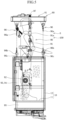
FIG. 3 is a schematic front view of the suspended platform according to one embodiment of the present disclosure; -
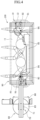
FIG. 4 is a schematic plan view of the suspended platform according to one embodiment of the present disclosure; -
FIG. 5 is a schematic side view of the suspended platform according to one embodiment of the present disclosure; -
FIG. 6 is a schematic front view of a suspension frame according to another embodiment of the present disclosure; -
FIG. 7 is a schematic plan view of a suspension frame according to still another embodiment of the present disclosure; -
FIG. 8 is a schematic side view of a suspended platform according to one embodiment of the present disclosure; and -
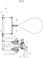
FIG. 9 is a schematic diagram of a suspended platform according to one embodiment of the present disclosure in a crane operation. - A work vehicle including a suspended platform according to an embodiment of the present disclosure will now be described in detail with reference to the accompanying drawings.
- As shown in
FIG. 1 , awork vehicle 1 including a suspended platform according to one embodiment of the present disclosure includes awork cage 10 to carry an operator, and anarm mechanism 60, which has a distal end movable to an intended position by at least one of a rotating mechanism 30, anextension mechanism 40, or aderricking mechanism 50 installed on avehicle body 20. Thework vehicle 1 includes a suspendedplatform 100, which includes asupport post 70, asuspension frame 80, andlift mechanisms 90. Thesupport post 70 is located at the distal end of thearm mechanism 60 and extends vertically. Thesuspension frame 80, from which thework cage 10 is suspended, is located at the upper end of thesupport post 70 to allow the operator to perform an operation above the upper end of thesupport post 70. Thelift mechanisms 90 raise or lower thework cage 10, suspended from thesuspension frame 80 withmultiple lanyards 91, to a work position. - More specifically, the
work vehicle 1 including the suspendedplatform 100 according to the present embodiment (hereinafter simply, the work vehicle) includes thesuspension frame 80, which allows the suspendedplatform 100 to be suspended from thesuspension frame 80 with thesupport post 70 at the distal end of thearm mechanism 60 installed on thevehicle body 20, and thelift mechanism 90, which raises or lowers thework cage 10 suspended from thesuspension frame 80 with thelanyards 91. Thework vehicle 1 can freely travel on roads or other surfaces. Thework vehicle 1 can move the distal end of thearm mechanism 60 on thevehicle body 20 to an intended position, and can raise or lower thework cage 10 suspended from thesuspension frame 80 at the distal end of thearm mechanism 60. An operator can thus perform an operation in thework cage 10 at an intended position within a wide operating range in which thework cage 10 is raised or lowered, and also an operation above thesuspension frame 80 without limitations, and can perform an operation in a wide range, and can perform an operation in a wide operation range. - The
work vehicle 1 according to the present embodiment is used as, for example, a bridge inspection vehicle, which is one of boom lift vehicles. Similarly to a known bridge inspection vehicle, thework vehicle 1 includes, on thevehicle body 20, thearm mechanism 60, which can move the distal end of the arm to an intended position. Thearm mechanism 60 may include one or more rotating mechanisms 30, one ormore extension mechanisms 40, and one or morederricking mechanisms 50. - As shown in
FIG. 1 , thearm mechanism 60 includes, for example, four booms, or afirst boom 61, asecond boom 62, athird boom 63, and afourth boom 64, from the base end to the distal end. - The
first boom 61 includes multiple extendable booms, which are extendable and retractable with theextension mechanism 40. Thefirst boom 61 is attached to a rotating platform 31 via aderricking shaft 51, which extends parallel to thevehicle body 20 of thederricking mechanism 50. The rotating platform 31 serves as the rotating mechanism 30 that rotates about the vertical axis on thevehicle body 20. Thefirst boom 61 can thus rotate and derrick. - The
second boom 62 includes multiple extendable booms, which are extendable and retractable with theextension mechanism 40. Thesecond boom 62 is attached to aleveling arm 52, which serves as thederricking mechanism 50 at the distal end of thefirst boom 61, via a rotating platform 32 that allows thethird boom 63 to rotate. - The
third boom 63 includes multiple extendable booms, which are extendable and retractable with theextension mechanism 40. Thethird boom 63 is attached via aderricking shaft 53, which serves as thederricking mechanism 50 at the distal end of thesecond boom 62. - The
fourth boom 64 is coupled to the distal end of thethird boom 63 via aderricking shaft 54 of thederricking mechanism 50, which allows derricking of thefourth boom 64. Awork cage mount 65, which can level thework cage 10, is located at the distal end of thefourth boom 64. - The rotating mechanism 30, the
extension mechanism 40, and thederricking mechanism 50 attached to the first tofourth booms 61 to 64 together form thearm mechanism 60, which moves the distal end of thefourth boom 64 to an intended position. - The rotating mechanism 30, the
extension mechanism 40, and thederricking mechanism 50 of thearm mechanism 60 include a hydraulic driving device, such as a hydraulic cylinder or a hydraulic motor, or an electric driving device. An operator operates thework vehicle 1 from an uppermost stop position S of the work cage 10 (described later) through anarm operation panel 66 for thearm mechanism 60. - Besides the hydraulic driving mechanism, the
work vehicle 1 has a power source ofAC 100 to 220 V fed from a generator installed on thevehicle body 20 to feed power to thearm operation panel 66. - The structure of the
arm mechanism 60 is a mere example applied to a bridge inspection vehicle. The number of booms or the arrangement of themechanisms arm mechanism 60 to an intended position. - The suspended
platform 100 is installed at the distal end of thearm mechanism 60, or specifically on thework cage mount 65 at the distal end of thefourth boom 64 in the present embodiment. - A vertically extending
support post 70 is mounted on thework cage mount 65. In the present embodiment, thesupport post 70 serves as arotating post 71, which rotates about a vertical axis on thework cage mount 65. - The
work cage mount 65, on which thesupport post 70 is mounted, may be rotated about the vertical axis by thearm mechanism 60. In this case, thesupport post 70 may be fixed, but can function similarly to therotating post 71. - The
work cage mount 65 included in thearm mechanism 60 may be rotated with an operation on a workcage operation panel 94, which will be described later. - For example, the rotating mechanism of the
rotating post 71 is driven by rotating a worm installed on thework cage mount 65 and engaged with a worm wheel attached to therotating post 71. The worm is rotated with a manual handle, or driven by a hydraulic motor or an electric motor. - The
suspension frame 80 is a wide frame 81 (refer toFIG. 4 ) recessed as viewed from above, or a substantially rectangular (refer toFIG. 6 )frame 82, mounted on the upper end of therotating post 71. Theframe rotating post 71 for attachment to therotating post 71. As shown inFIG. 8 , instead of being a flat frame, thesuspension frame 80 may be aframe 83 combined with sides each having a downward recess in vertical cross section (refer toFIGS. 7 and8 ). Instead of having a rectangular cross section, thesuspension frame 80 may have a cross section of another shape that allows an operator in thework cage 10 to perform operations above thesuspension frame 80. - The
suspension frame 80 allows an operator to perform operations in an upper area from inside theframe - As shown in
FIGS. 5 to 8 , thelift mechanisms 90, which raise or lower thework cage 10, are attached to theframe suspension frame 80. Thelift mechanisms 90 includemultiple lanyards 91. For example, themultiple lanyards 91 include two wire ropes, and are suspended with their upper ends fixed. - As shown in
FIGS. 2 ,5 ,7 , and8 , atwist remover 91a for eachlanyard 91 is arranged between thesuspension frame 80 and thelanyard 91. Thetwist remover 91a allows thelanyard 91 to rotate about the center axis to prevent thelanyard 91 from being twisted. - The two suspended
lanyards 91 are wound around the sheaves ofendless winders 92 installed on thework cage 10. For example, twoendless winders 92, which serve as thelift mechanisms 90, are installed on the left and right parts of thework cage 10. Thework cage 10 has the two lanyards (wire ropes) 91 fixed to and suspended from thesuspension frame 80 and wound around the sheaves of theendless winders 92. Thework cage 10 is then raised and lowered while changing the winding positions under a frictional force between thelanyards 91 and the sheaves of theendless winders 92. - The
endless winders 92 return to the original positions with manual rotations of the sheaves if theendless winders 92 malfunction. - The
work cage 10 includes arectangular work floor 11, on which operators stand. Thework floor 11 is placed substantially perpendicular to the target wall surface during operation. Thework floor 11 is surrounded bypanels 12 to allow the operators to perform safe operations. As appropriate, handrails, sheets, or nets for protection against falling objects or debris resulting from the operation are attached to thework cage 10. - As shown in
FIGS. 2 ,5 , and8 , windingreels 95 for winding the twolanyards 91 are attached in a self-rotatable manner below thework floor 11 of thework cage 10. The windingreels 95 with a cage shape rotate in response to a push or pull of thelanyards 91 to coil up thelanyards 91 for storage. - The
endless winders 92 are driven by a battery (not shown) mounted on thework cage 10. Abattery panel 93, which contains a battery, and the workcage operation panel 94 are installed on thework cage 10. The battery mounted on thework cage 10 is rechargeable with power from an external power supply through a charging connector on thearm operation panel 66 when thework cage 10 is at the uppermost stop position S. - Regenerated current can be recovered to the battery from the driving motors of the
endless winders 92 for energy saving. - The length of the
lanyards 91 suspended from thesuspension frame 80 can be adjusted by theendless winders 92 to correspond to the range in which thework cage 10 is raised or lowered. Thus, the operator can perform operations on the wall surface without limitations while raising or lowering thework cage 10 within an intended range. - To perform operations from the
work cage 10, the rotational position of thesuspension frame 80 about a vertical axis is adjusted by the rotation of therotating post 71. Thework cage 10 can thus be placed parallel to the target wall surface. - As shown in
FIG. 9 , for example, the suspendedplatform 100 may have theendless winders 92 fixed to thework cage mount 65 at the distal end of thearm mechanism 60 as winches, instead of being installed on thework cage 10. - The
lanyards 91 may be wired from the fixedendless winders 92 to thesuspension frame 80, and the suspendedlanyards 91 such as wire ropes may be connected to thework cage 10 to be wound up or unwound to raise or lower thework cage 10. This structure may include a wireless operation panel for operating the winches, such as theendless winders 92, from thework cage 10, and a safe return unit additionally arranged to allow the operator to return to an operation start point when, for example, the winches such as theendless winders 92 malfunction. - The
endless winders 92 installed on thework cage mount 65 allow asuspension beam 98 including ahook 98a to be arranged, in place of thework cage 10, at an intermediate point between thelanyards 91 suspended from thesuspension frame 80, and enable a crane operation through the wireless operation panel. - In some embodiments, the
endless winders 92 installed on thework cage 10 may be driven by an external power (power supply from a generator or other devices), in place of a battery, through power cables. This structure includes power cables and reels. - The
work vehicle 1 including the suspendedplatform 100 includes an interlock mechanism for safe operation. The interlock mechanism operates mechanically and electrically. - During the operation of the suspended
platform 100, the interlock mechanism disables the operation of thearm mechanism 60. More specifically, thearm operation panel 66 for thearm mechanism 60 is installed on thesupport post 70 at the distal end of thearm mechanism 60, or on therotating post 71 in the present embodiment. Thus, thearm operation panel 66 is accessible to the operator only when thework cage 10 suspended from thesuspension frame 80 is at the uppermost stop position S. Thus, after thework cage 10 is started to move (be lowered), thearm operation panel 66 becomes physically inaccessible to the operator to disable the operation of thearm mechanism 60. - For a mechanical lock mechanism, the
work vehicle 1 includesfastening mechanisms 96 between thework cage 10 and thesuspension frame 80 to fix thework cage 10 at the uppermost stop position S to thesuspension frame 80 to prevent thework cage 10 from moving (from being lowered). When the upper ends of thefastening mechanisms 96 are fixed to thesuspension frame 80 and hooks 96b at the lower ends of thefastening mechanisms 96 are hooked through the openings in thebrackets 96c on thework cage 10, thework cage 10 is fastened to thesuspension frame 80. Thefastening mechanisms 96 enable simple fastening of thework cage 10 by, for example, slightly raising thework cage 10 from the uppermost stop position S, hooking thehooks 96b through thebrackets 96c on thework cage 10, and then lowering thework cage 10 to the uppermost stop position S. Thework cage 10 is released from the fastened state by being slightly raised and disconnected from thefastening mechanisms 96. - The
fastening mechanisms 96 fasten thework cage 10 to thesuspension frame 80 to prevent thework cage 10 from moving (from being lowered). Thus, the twolanyards 91 are left unloaded. - A
load detector 97 is attached to eachlanyard 91 for suspending thework cage 10. Theload detector 97 electrically detects thework cage 10 at the uppermost stop position S at which thelanyard 91 is unloaded. In other words, for thefastening mechanisms 96 to detect thework cage 10 fastened to thesuspension frame 80, a load cell is installed in thesuspension frame 80 to serve as aload detector 97. When thelanyard 91 is suspended from thesuspension frame 80, theload detector 97 electrically detects the load on the load cell smaller than a predetermined value. - A mechanical system including a striker attached to the
work cage 10 and a limit switch installed on thesuspension frame 80 may be used as theload detector 97. The limit switch may obtain an electric signal indicating that thework cage 10 is at the uppermost stop position S. In some embodiments, a proximity sensor may be used to detect the position of thework cage 10 to obtain an electric signal indicating that thework cage 10 is at the uppermost stop position S. - The
load detector 97 can electrically detect thework cage 10 at the uppermost stop position S at which thelanyard 91 is unloaded. This interlocks thework cage 10 for operations such as being raised and lowered. - Unless the
work cage 10 is at the uppermost stop position S, thearm mechanism 60 is interlocked to allow no operation. - The
work vehicle 1 including the suspended platform with the above structure is used to perform operations in the following manner. - The
work vehicle 1 travels on the road to a work site. - At the work site, an operator prepares to start operations in the
vehicle body 20, such as a typical bridge inspection vehicle or a boom lift vehicle. More specifically, the operator performs pre-operation checks, checks the parking conditions, including whether the vehicle is parked on a flat road surface or the state of the parking brake, and manipulates an outrigger. - The operator then enters the
work cage 10 suspended at the uppermost stop position S at the distal end of thearm mechanism 60 and fastened with thefastening mechanisms 96. - Thereafter, the operator in the
work cage 10 operates thearm operation panel 66 attached to therotating post 71 to move thework cage 10 to an intended work position (operation start point) with themechanisms arm mechanism 60. - The
arm operation panel 66 is operable while thework cage 10 is interlocked, in which thework cage 10 is at the uppermost stop position S and mechanically fastened with thefastening mechanisms 96. This is detected by theload detector 97 that electrically detects the unloadedlanyard 91 or electrically detects thework cage 10 at the uppermost stop position S. This structure ensures the safety of an operation. - In addition, the
rotating post 71 is rotated by the operation on the workcage operation panel 94 to place thework cage 10 parallel to the wall surface. This completes the preparations. - To start the operation with the
work cage 10, thefastening mechanisms 96 release mechanical fastening of thework cage 10. Thework cage 10 is slightly raised to unhook thehooks 96b of thefastening mechanisms 96 from thebrackets 96c on thework cage 10. - In response to releasing of the fastened state, the
load detector 97 detects the loadedlanyard 91, or detects thework cage 10 moved from the uppermost stop position S (e.g., thework cage 10 is slightly lowered). Thus, thearm operation panel 66 is interlocked, disabling operations on thearm mechanism 60. The position of thesuspension frame 80, from which thework cage 10 is suspended, is thus prevented from being unintentionally changed by thearm mechanism 60. - The operator in the
work cage 10 can perform operations also above thesuspension frame 80. Adjusting the uppermost stop position S of thearm mechanism 60 in advance thus enables operations above thesuspension frame 80. - The operator operates the work
cage operation panel 94 to raise or lower thework cage 10 to perform operations below the uppermost stop position S. For a curved work surface, the operator operates the workcage operation panel 94 to rotate therotating post 71 to change the orientation of thework cage 10 to place thework cage 10 parallel to the wall surface for performing the operation. - After performing an operation by raising or lowering the distal end of the
arm mechanism 60 to intended positions, the operator raises thework cage 10 to return to the uppermost stop position S to complete the operation in a single up-down range. - After the
work cage 10 is fastened at the uppermost stop position S, the operator in thework cage 10 operates thearm operation panel 66 to repeatedly move the distal end of thearm mechanism 60 to the subsequent work position while performing operations by raising or lowering thework cage 10 in the same manner. - When returned to the uppermost stop position S, the battery mounted on the
work cage 10 is recharged as appropriate. - After the operation on the entire wall surface is complete by repeatedly moving to another operation start point with the
arm mechanism 60 and raising and lowering of thework cage 10 in combination, thearm mechanism 60 is operated to return to the initial position, allowing thework vehicle 1 to travel. - This completes the operation.
- To use the
work vehicle 1 as a crane truck, as shown inFIG. 9 , theendless winders 92 are installed at the distal end of thearm mechanism 60, thesuspension beam 98 is suspended with twolanyards 91, and a cargo is suspended using thehook 98a on thesuspension beam 98. Then, theendless winders 92 are operated through the wireless operation panel. Thus, thework vehicle 1 can readily be used as a crane truck. - The above embodiment only describes the operation of raising or lowering the work cage suspended from the suspension frame. In some embodiments, the work cage may include a traversing mechanism movable lateral direction to further widen the operating range.
- The present disclosure is not limited to the above embodiment, and each component may be modified without departing from the scope of the invention as defined by the claims.
- As described in detail in the embodiment, the work vehicle including a suspended platform according to an exemplary embodiment of the present disclosure is the
work vehicle 1 including thework cage 10 to carry an operator, and thearm mechanism 60, which moves its distal end to an intended position by at least one of the rotating mechanism 30, theextension mechanism 40, or thederricking mechanism 50 installed on thevehicle body 20. Thework vehicle 1 includes the suspendedplatform 100, which includes thesupport post 70, thesuspension frame 80, and thelift mechanisms 90. Thesupport post 70 is located at the distal end of thearm mechanism 60 and extends vertically. Thesuspension frame 80, from which thework cage 10 is suspended, is mounted on the upper end of thesupport post 70 and located outside thework cage 10 to allow an operator to perform an operation above the upper end of thesupport post 70. Thelift mechanisms 90 raise or lower thework cage 10, suspended from thesuspension frame 80 with thelanyards 91, to a work position. Theoperation panel 66 for thearm mechanism 60 is operable from thework cage 10 at the upper stop position S and inoperable from thework cage 10 at a raised or lowered position. Thus, thework vehicle 1 can transport the suspendedplatform 100 by traveling a public road. Thework cage 10 is thus movable to an intended position from above a road by thearm mechanism 60, and the raising or lowering of thework cage 10 allows a wide operating range. As in a boom lift vehicle, thework cage 10 suspended from thesuspension frame 80 also enables an operation above thework cage 10, unlike known suspended platform. - The
work cage 10 of the suspendedplatform 100 is thus movable to an intended position in an operating range without limitations, thus allowing an operation in a wide operating range. - This structure facilitates transportation to a work site or operational preparation or withdrawal at the work site, thus greatly improving the work efficiency as compared with when a work cage is suspended from, for example, a rooftop.
- The
operation panel 66 for thearm mechanism 60 is operable from thework cage 10 at the uppermost stop position S and inoperable from thework cage 10 at a raised or lowered position. Thus, thearm mechanism 60 becomes inoperable when thework cage 10 is raised or lowered to allow the operator in thework cage 10 to perform an intended operation safely.
The following paragraphs are part of the disclosure, but are not part of the invention. - A work vehicle including a suspended platform according to an exemplary embodiment of the present disclosure is the
work vehicle 1 including thework cage 10 to carry an operator, and thearm mechanism 60, which moves its distal end to an intended position by at least one of the rotating mechanism 30, theextension mechanism 40, or thederricking mechanism 50 installed on thevehicle body 20. Thework vehicle 1 includes the suspendedplatform 100, which includes thesupport post 70, thesuspension frame 80, and thelift mechanisms 90. Thesupport post 70 is located at the distal end of thearm mechanism 60 and extends vertically. Thesuspension frame 80, from which thework cage 10 is suspended, is mounted on the upper end of thesupport post 70 and located outside thework cage 10 to allow an operator to perform an operation above the upper end of thesupport post 70. Thelift mechanisms 90 raise or lower thework cage 10, suspended from thesuspension frame 80 with thelanyards 91, to a work position. Thework vehicle 1 includes thefastening mechanisms 96 between thework cage 10 and thesuspension frame 80 to fasten thework cage 10 at the uppermost stop position S. Thework vehicle 1 includes theload detector 97 installed in thesuspension frame 80 to detect a fastened state of thework cage 10 at the uppermost stop position S based on the load on thelanyard 91. Thus, the suspendedplatform 100 is transportable through a public road. Thework cage 10 is thus movable to an intended position from above a road by thearm mechanism 60, and is raised or lowered to allow an operation in a wide operating range. As in a boom lift vehicle, thework cage 10 suspended from thesuspension frame 80 also enables an operation above thework cage 10, unlike known suspended platform. - The
work cage 10 of the suspendedplatform 100 is movable to an intended position in an operating range without limitations, thus allowing an operation in a wide operating range. - This structure facilitates transportation to a work site or operational preparation or withdrawal at the work site, thus greatly improving the work efficiency as compared with when a work cage is suspended from, for example, a rooftop.
- The
work vehicle 1 includes thefastening mechanisms 96 between thework cage 10 and thesuspension frame 80 to fasten thework cage 10 at the uppermost stop position S. Thework vehicle 1 includes theload detector 97 installed in thesuspension frame 80 to detect a fastened state of thework cage 10 at the uppermost stop position S based on the load on thelanyard 91. Thefastening mechanisms 96 can firmly fasten thework cage 10 at the uppermost stop position S, and theload detector 97 can detect an electric signal indicating the position of thework cage 10. Thus, the suspendedplatform 100 is interlocked depending on the position of thework cage 10, thus allowing safe operations. - A work vehicle including a suspended platform according to an exemplary embodiment of the present disclosure is the
work vehicle 1 including thework cage 10 to carry an operator, and thearm mechanism 60, which moves its distal end to an intended position at least one of the rotating mechanism 30, theextension mechanism 40, or thederricking mechanism 50 installed on thevehicle body 20. Thework vehicle 1 includes the suspendedplatform 100, which includes thesupport post 70, thesuspension frame 80, and thelift mechanism 90. Thesupport post 70 is located at the distal end of thearm mechanism 60 and extends vertically. Thesuspension frame 80, from which thework cage 10 is suspended, is mounted on the upper end of thesupport post 70 and located outside thework cage 10 to allow an operator to perform an operation above the upper end of thesupport post 70. Thelift mechanism 90 raises or lowers thework cage 10, suspended from thesuspension frame 80 with thelanyards 91, to a work position. Thelift mechanism 90 in the suspendedplatform 100 is driven by a battery mounted on thework cage 10. Thework cage 10 is rechargeable at the uppermost stop position S with power from an external power supply. Thus, the suspendedplatform 100 is transportable through a public road. Thework cage 10 is thus movable to an intended position from above a road by thearm mechanism 60, and the raising or lowering of thework cage 10 allows an operation in a wide operating range. As in a boom lift vehicle, thework cage 10 suspended from thesuspension frame 80 also enables an operation above thework cage 10, unlike known suspended platform. - The
work cage 10 of the suspendedplatform 100 is movable to an intended position in an operating range without limitations, thus allowing an operation in a wide operating range. - This structure facilitates transportation to a work site or operational preparation or withdrawal at the work site, thus greatly improving the work efficiency as compared with when a work cage is suspended from, for example, a rooftop.
- The
lift mechanism 90 in the suspendedplatform 100 is driven by a battery mounted on thework cage 10. Thework cage 10 is rechargeable at the uppermost stop position S with power from an external power supply. Thelift mechanism 90 thus has no power cable between thearm mechanism 60 and thework cage 10. This structure thus eliminates operational obstructions or limitations in the operating range, and enables easy recharging of thework cage 10 at the uppermost stop position S. - In the
work vehicle 1 including a suspended platform according to an exemplary embodiment of the present disclosure, thesupport post 70 includes therotating post 71, which rotates about a vertical axis. Thus, the direction of thesuspension frame 80 is changeable about the vertical axis by rotating therotating post 71 to adjust the orientation of thework cage 10 for performing operations on, for example, wall surfaces. End of paragraphs not being part of the invention but part of the disclosure. - In the
work vehicle 1 including a suspended platform according to an exemplary embodiment in accordance withclaim 1 of the present disclosure, theoperation panel 66 for thearm mechanism 60 is operable from thework cage 10 at the uppermost stop position S and inoperable from thework cage 10 at a raised or lowered position. Thus, an operator in the raised or loweredwork cage 10 is unable to operate thearm mechanism 60, thus allowing the operator in thework cage 10 to perform an intended operation safely.
The following paragraphs are part of the disclosure, but are not part of the invention. - The
work vehicle 1 including a suspended platform according to an exemplary embodiment of the present disclosure includes thefastening mechanisms 96 between thework cage 10 and thesuspension frame 80 to fasten thework cage 10 at the uppermost stop position S. Thework vehicle 1 includes theload detector 97 installed in thesuspension frame 80 to detect a fastened state of thework cage 10 at the uppermost stop position S based on the load on thelanyard 91. Thefastening mechanisms 96 can firmly fasten thework cage 10 at the uppermost stop position S, and theload detector 97 detects an electric signal indicating the position of thework cage 10. Thus, the suspended platform is interlocked depending on the position of thework cage 10, thus allowing an operator to perform safe operations. - In the work vehicle including a suspended platform according to an exemplary embodiment of the present disclosure, the
lift mechanisms 90 in the suspendedplatform 100 are driven by thebattery panel 93 mounted on thework cage 10. Thework cage 10 is rechargeable at the uppermost stop position S with power from an external power supply. Thelift mechanisms 90 thus have no power cable between thearm mechanism 60 and thework cage 10. This structure eliminates operation obstructions or limitations in the operating range, and allows easy recharging at the uppermost stop position S.
End of paragraphs not being part of the invention but part of the disclosure. - The foregoing describes some example embodiments for explanatory purposes. Although the foregoing discussion has presented specific embodiments, persons skilled in the art will recognize that changes may be made in form and detail without departing from the scope of the invention. Accordingly, the specification and drawings are to be regarded in an illustrative rather than a restrictive sense. This detailed description, therefore, is not to be taken in a limiting sense, and the scope of the invention is defined only by the included claims.
-
- 1
- Work vehicle (Work vehicle including suspended platform)
- 10
- Work cage
- 11
- Work floor
- 12
- Panel
- 20
- Vehicle body
- 30
- Rotating mechanism
- 31
- Rotating platform
- 32
- Rotating platform
- 40
- Extension mechanism
- 50
- Derricking mechanism
- 51
- Derricking shaft
- 52
- Leveling arm
- 53
- Derricking shaft
- 54
- Derricking shaft
- 60
- Arm mechanism
- 61
- First boom
- 62
- Second boom
- 63
- Third boom
- 64
- Fourth boom
- 65
- Work cage mount
- 66
- Arm operation panel
- 70
- Support post
- 71
- Rotating post
- 80
- Suspension frame
- 81
- Frame
- 82
- Frame
- 83
- Frame
- 90
- Lift mechanism
- 91
- Lanyard
- 91a
- Twist remover
- 92
- Endless winder
- 93
- Battery panel
- 94
- Work cage operation panel
- 95
- Winding reel
- 96
- Fastening mechanism
- 96a
- Fastening rod
- 96b
- Hook
- 96c
- Bracket
- 97
- Load detector
- 98
- Suspension beam
- 98a
- Hook
- 100
- Suspended platform
- S
- Uppermost stop position
Claims (4)
- A work vehicle (1) including a suspended platform (100), the work vehicle (1) comprising:a work cage (10) configured to carry an operator;an arm mechanism (60) having a distal end, the distal end being movable to an intended position by at least one of a rotating mechanism (30), an extension mechanism (40), or a derricking mechanism (50) that are installed on a vehicle body (20); andthe suspended platform (100) comprisinga support post (70) located at the distal end of the arm mechanism (60) and extending vertically,a suspension frame (80) from which the work cage (10) is suspended, the suspension frame ( 80) being mounted on an upper end of the support post (70), being located outside the work cage (10) allowing the operator to perform an operation on a portion above the upper end of the support post (70), anda lift mechanism (90) configured to raise or lower the work cage (10) to a work position, the work cage (10) being suspended from the suspension frame (80) with a plurality of lanyards (92),characterised in thatthe arm mechanism (60) comprises an operation panel (66) that is operable from the work cage (10) at an uppermost stop position (S) and inoperable from the work cage (10) at a raised or lowered position.
- Work vehicle (1) according to claim 1, further comprising :a fastening mechanism (96) located between the work cage (10) and the suspension frame (80) to fasten the work cage (10) at an uppermost stop position (S); anda load detector (97) installed in the suspension frame (80)to detect a fastened state of the work cage (10) at the uppermost stop position (S) based on a load on at least one of the lanyards (91).
- The work vehicle (1) according to claim 1 or 2, wherein the lift mechanism (90) in the suspended platform (100) is driven by a battery mounted on the work cage (10), and
the work cage (10) has the battery rechargeable at an uppermost stop position (S) with power from an external power supply. - The work vehicle (1) according to any one of claims 1 to 3, wherein the support post (70) comprises a rotating post configured to rotate about a vertical axis.
Applications Claiming Priority (2)
| Application Number | Priority Date | Filing Date | Title |
|---|---|---|---|
| JP2016203811A JP6189512B1 (en) | 2016-10-17 | 2016-10-17 | Work vehicle with gondola device |
| PCT/JP2017/034298 WO2018074140A1 (en) | 2016-10-17 | 2017-09-22 | Work vehicle provided with gondola device |
Publications (3)
| Publication Number | Publication Date |
|---|---|
| EP3527527A1 EP3527527A1 (en) | 2019-08-21 |
| EP3527527A4 EP3527527A4 (en) | 2020-06-17 |
| EP3527527B1 true EP3527527B1 (en) | 2025-06-18 |
Family
ID=59720507
Family Applications (1)
| Application Number | Title | Priority Date | Filing Date |
|---|---|---|---|
| EP17862772.5A Active EP3527527B1 (en) | 2016-10-17 | 2017-09-22 | Work vehicle provided with gondola device |
Country Status (7)
| Country | Link |
|---|---|
| US (1) | US10988362B2 (en) |
| EP (1) | EP3527527B1 (en) |
| JP (1) | JP6189512B1 (en) |
| CN (1) | CN109843779B (en) |
| AU (1) | AU2017346647B2 (en) |
| SG (1) | SG11201903366VA (en) |
| WO (1) | WO2018074140A1 (en) |
Families Citing this family (23)
| Publication number | Priority date | Publication date | Assignee | Title |
|---|---|---|---|---|
| JP6445151B2 (en) * | 2015-05-22 | 2018-12-26 | 富士フイルム株式会社 | Robot apparatus and movement control method of robot apparatus |
| JP6189512B1 (en) | 2016-10-17 | 2017-08-30 | 日本ビソー株式会社 | Work vehicle with gondola device |
| JP6261800B1 (en) * | 2017-07-12 | 2018-01-17 | 日本ビソー株式会社 | Working gondola device and working vehicle equipped with the same |
| US20200079632A1 (en) * | 2018-09-12 | 2020-03-12 | Jlg Industries, Inc. | Below grade access platform |
| US12202715B2 (en) * | 2020-01-16 | 2025-01-21 | Xtreme Manufacturing, Llc | Telehandler boom auxiliary control panel |
| US11919756B2 (en) | 2020-02-04 | 2024-03-05 | Xtreme Manufacturing, Llc | Aerial work vehicle boom auxiliary control panel |
| CN111441243B (en) * | 2020-04-13 | 2022-03-25 | 衡橡科技股份有限公司 | Telescopic vehicle body stay cable reinforcing mechanism of inspection vehicle |
| US11945123B2 (en) | 2020-04-28 | 2024-04-02 | Altec Industries, Inc. | Head mounted display for remote operation of machinery |
| CN111827109A (en) * | 2020-05-10 | 2020-10-27 | 广西长长路桥建设有限公司 | Road and bridge inspection platform |
| JP6758699B1 (en) * | 2020-07-07 | 2020-09-23 | 株式会社関東技研 | Bridge girder inspection device |
| CA3210378A1 (en) * | 2021-03-25 | 2022-09-29 | Riccardo Magni | Self-propelled work vehicle |
| US20230011782A1 (en) * | 2021-07-07 | 2023-01-12 | Terex South Dakota, Inc. | Link assembly for an aerial lift assembly |
| CN114033151B (en) * | 2021-11-25 | 2024-12-24 | 绍兴文理学院 | A high-altitude work hanging basket system suitable for various wall conditions |
| US11794359B1 (en) | 2022-07-28 | 2023-10-24 | Altec Industries, Inc. | Manual operation of a remote robot assembly |
| US11839962B1 (en) | 2022-07-28 | 2023-12-12 | Altec Industries, Inc. | Rotary tool for remote power line operations |
| US11717969B1 (en) | 2022-07-28 | 2023-08-08 | Altec Industries, Inc. | Cooperative high-capacity and high-dexterity manipulators |
| US11697209B1 (en) * | 2022-07-28 | 2023-07-11 | Altec Industries, Inc. | Coordinate mapping for motion control |
| US11689008B1 (en) | 2022-07-28 | 2023-06-27 | Altec Industries, Inc. | Wire tensioning system |
| US11660750B1 (en) | 2022-07-28 | 2023-05-30 | Altec Industries, Inc. | Autonomous and semi-autonomous control of aerial robotic systems |
| US11749978B1 (en) | 2022-07-28 | 2023-09-05 | Altec Industries, Inc. | Cross-arm phase-lifter |
| JP7637184B2 (en) * | 2023-06-12 | 2025-02-27 | 東芝エレベータ株式会社 | Gondola Equipment |
| KR102710064B1 (en) * | 2024-07-23 | 2024-09-25 | 주식회사 제다코리아 | Work vehicle with basket |
| KR102756867B1 (en) * | 2024-07-23 | 2025-01-21 | 주식회사 제다코리아 | Vehicle for inspection of bridge and pier |
Family Cites Families (24)
| Publication number | Priority date | Publication date | Assignee | Title |
|---|---|---|---|---|
| US4456093A (en) * | 1981-06-16 | 1984-06-26 | Interstate Electronics Corp. | Control system for aerial work platform machine and method of controlling an aerial work platform machine |
| DE3206964A1 (en) * | 1982-02-26 | 1983-09-22 | Alfred W. Weber Maschinenfabrik GmbH & Co, 2800 Bremen | Device for balancing the position of a working basket |
| CN85103124A (en) | 1985-04-23 | 1986-10-22 | 日本轻金属有限公司 | Overhaul vehicle for elevated highway bridge construction |
| US5713430A (en) * | 1996-02-29 | 1998-02-03 | Cohen; Schachar | Device for treating exterior surfaces for structures |
| JPH09256626A (en) * | 1996-03-25 | 1997-09-30 | Nihon Bisoh Co Ltd | Hangingly supporting device of external wall working machine for building |
| JP3410352B2 (en) * | 1998-02-16 | 2003-05-26 | 日立建機株式会社 | Mobile gondola |
| KR100599080B1 (en) * | 1998-04-23 | 2006-11-30 | 가부시키가이샤 아이치 코포레이션 | Expansion boom |
| JP3314180B2 (en) * | 1999-04-22 | 2002-08-12 | 三井金属エンジニアリング株式会社 | Work cage lifting device |
| JP2002053297A (en) | 2000-08-08 | 2002-02-19 | Kyokuto Kaihatsu Kogyo Co Ltd | Bridge inspecting vehicle |
| JP2003128392A (en) | 2001-10-30 | 2003-05-08 | Aichi Corp | Aerial work vehicle |
| GB2384481B (en) * | 2002-01-24 | 2004-09-22 | Cradle Access Developments Ltd | Mobile aerial work platforms |
| US20040026171A1 (en) * | 2002-08-09 | 2004-02-12 | Hsing-San Chang | Multifunctional highrise escaping device capable of moving up and down, left and right, forward and reward |
| US20080283334A1 (en) * | 2007-01-09 | 2008-11-20 | Edsel Wakefield Fickey | Tree glider |
| KR100899590B1 (en) * | 2007-06-14 | 2009-05-26 | 장경호 | Balance lift |
| JP5086147B2 (en) | 2008-03-25 | 2012-11-28 | 日本ビソー株式会社 | Gondola with curing device |
| FR2950618B1 (en) * | 2009-09-28 | 2011-10-21 | Haulotte Group | LIFT BOOM AND METHOD OF CONTROLLING SUCH NACELLE |
| CN101691197A (en) * | 2009-10-22 | 2010-04-07 | 三一集团有限公司 | Self-propelled lifter |
| CN102166394B (en) * | 2011-04-18 | 2012-09-26 | 苏畅 | High-altitude fire prevention rescue device for high-rise building |
| CN103243647B (en) * | 2013-05-23 | 2015-08-05 | 山东大学 | A kind of Novel hybrid bridge detection vehicle |
| JP2016011211A (en) * | 2014-06-03 | 2016-01-21 | 株式会社アイチコーポレーション | Vehicle for high lift work |
| US9695024B2 (en) | 2015-01-23 | 2017-07-04 | Jeremy Herauf | Unique roadworthy sidewalk boom trailer, having on-site interchangeable boom, on-site interchangeable ladder, and on-site interchangeable catwalk sized to access narrow openings and nooks over and under bridges |
| ES2806267T3 (en) * | 2015-04-03 | 2021-02-17 | Iveco Magirus | Fall protection device |
| JP6465352B2 (en) | 2015-04-23 | 2019-02-06 | 本田技研工業株式会社 | Side curtain airbag fixing structure |
| JP6189512B1 (en) | 2016-10-17 | 2017-08-30 | 日本ビソー株式会社 | Work vehicle with gondola device |
-
2016
- 2016-10-17 JP JP2016203811A patent/JP6189512B1/en active Active
-
2017
- 2017-09-22 US US16/341,535 patent/US10988362B2/en active Active
- 2017-09-22 SG SG11201903366VA patent/SG11201903366VA/en unknown
- 2017-09-22 CN CN201780063717.2A patent/CN109843779B/en active Active
- 2017-09-22 WO PCT/JP2017/034298 patent/WO2018074140A1/en not_active Ceased
- 2017-09-22 EP EP17862772.5A patent/EP3527527B1/en active Active
- 2017-09-22 AU AU2017346647A patent/AU2017346647B2/en active Active
Also Published As
| Publication number | Publication date |
|---|---|
| JP2018065633A (en) | 2018-04-26 |
| JP6189512B1 (en) | 2017-08-30 |
| CA3041030A1 (en) | 2018-04-26 |
| EP3527527A4 (en) | 2020-06-17 |
| CN109843779B (en) | 2021-06-04 |
| AU2017346647B2 (en) | 2022-08-11 |
| CN109843779A (en) | 2019-06-04 |
| US20190256335A1 (en) | 2019-08-22 |
| SG11201903366VA (en) | 2019-05-30 |
| WO2018074140A1 (en) | 2018-04-26 |
| EP3527527A1 (en) | 2019-08-21 |
| US10988362B2 (en) | 2021-04-27 |
| AU2017346647A1 (en) | 2019-06-06 |
Similar Documents
| Publication | Publication Date | Title |
|---|---|---|
| US10988362B2 (en) | Work vehicle including suspended platform | |
| CN110799443B (en) | Nacelle equipment for construction and construction vehicle equipped with nacelle equipment for construction | |
| JP2012532259A (en) | Vehicle parking building elevator system | |
| JP4138864B1 (en) | Crane type gondola structure | |
| JPH0530758B2 (en) | ||
| CA3041030C (en) | Work vehicle including suspended platform | |
| JP2008156087A (en) | Handling method and equipment for traveling cart | |
| CN102259803B (en) | Mobile crane | |
| JP7189490B2 (en) | Auxiliary device for position adjustment and mobile crane | |
| JP4187445B2 (en) | crane | |
| EP1801318A1 (en) | Vehicle for transporting materials along exteriors of buildings | |
| JP7132821B2 (en) | Work vehicle safety device | |
| JPH085197Y2 (en) | Shuttle boom type jib crane | |
| JP7498148B2 (en) | Self-propelled bridge crane | |
| KR200234050Y1 (en) | Crane Apparatus for Automobile | |
| JP7120432B1 (en) | Seat hanging assistance system and seat hanger moving device | |
| JPH08208155A (en) | Elevator for construction work | |
| CN110040645A (en) | Small-sized material elevator | |
| JPS6365596B2 (en) | ||
| JP2005082280A (en) | Crane equipment | |
| JPS59138593A (en) | Sheave device | |
| JPH0194160A (en) | Hanging construction method for large retaining mold | |
| AU2005229758A1 (en) | Hoist | |
| JPS6357360B2 (en) | ||
| JPS5982292A (en) | Cargo handling equipment |
Legal Events
| Date | Code | Title | Description |
|---|---|---|---|
| STAA | Information on the status of an ep patent application or granted ep patent |
Free format text: STATUS: THE INTERNATIONAL PUBLICATION HAS BEEN MADE |
|
| PUAI | Public reference made under article 153(3) epc to a published international application that has entered the european phase |
Free format text: ORIGINAL CODE: 0009012 |
|
| STAA | Information on the status of an ep patent application or granted ep patent |
Free format text: STATUS: REQUEST FOR EXAMINATION WAS MADE |
|
| 17P | Request for examination filed |
Effective date: 20190503 |
|
| AK | Designated contracting states |
Kind code of ref document: A1 Designated state(s): AL AT BE BG CH CY CZ DE DK EE ES FI FR GB GR HR HU IE IS IT LI LT LU LV MC MK MT NL NO PL PT RO RS SE SI SK SM TR |
|
| AX | Request for extension of the european patent |
Extension state: BA ME |
|
| DAV | Request for validation of the european patent (deleted) | ||
| DAX | Request for extension of the european patent (deleted) | ||
| A4 | Supplementary search report drawn up and despatched |
Effective date: 20200519 |
|
| RIC1 | Information provided on ipc code assigned before grant |
Ipc: B66F 11/04 20060101AFI20200513BHEP Ipc: E01D 19/10 20060101ALI20200513BHEP |
|
| REG | Reference to a national code |
Ref country code: DE Ref legal event code: R079 Free format text: PREVIOUS MAIN CLASS: B66F0009060000 Ipc: B66F0011040000 Ref country code: DE Ref legal event code: R079 Ref document number: 602017090056 Country of ref document: DE Free format text: PREVIOUS MAIN CLASS: B66F0009060000 Ipc: B66F0011040000 |
|
| GRAP | Despatch of communication of intention to grant a patent |
Free format text: ORIGINAL CODE: EPIDOSNIGR1 |
|
| STAA | Information on the status of an ep patent application or granted ep patent |
Free format text: STATUS: GRANT OF PATENT IS INTENDED |
|
| RIC1 | Information provided on ipc code assigned before grant |
Ipc: E01D 19/10 20060101ALI20220610BHEP Ipc: B66F 11/04 20060101AFI20220610BHEP |
|
| INTG | Intention to grant announced |
Effective date: 20220627 |
|
| GRAJ | Information related to disapproval of communication of intention to grant by the applicant or resumption of examination proceedings by the epo deleted |
Free format text: ORIGINAL CODE: EPIDOSDIGR1 |
|
| STAA | Information on the status of an ep patent application or granted ep patent |
Free format text: STATUS: REQUEST FOR EXAMINATION WAS MADE |
|
| STAA | Information on the status of an ep patent application or granted ep patent |
Free format text: STATUS: EXAMINATION IS IN PROGRESS |
|
| INTC | Intention to grant announced (deleted) | ||
| 17Q | First examination report despatched |
Effective date: 20221104 |
|
| GRAP | Despatch of communication of intention to grant a patent |
Free format text: ORIGINAL CODE: EPIDOSNIGR1 |
|
| STAA | Information on the status of an ep patent application or granted ep patent |
Free format text: STATUS: GRANT OF PATENT IS INTENDED |
|
| INTG | Intention to grant announced |
Effective date: 20241002 |
|
| GRAJ | Information related to disapproval of communication of intention to grant by the applicant or resumption of examination proceedings by the epo deleted |
Free format text: ORIGINAL CODE: EPIDOSDIGR1 |
|
| GRAP | Despatch of communication of intention to grant a patent |
Free format text: ORIGINAL CODE: EPIDOSNIGR1 |
|
| INTG | Intention to grant announced |
Effective date: 20250117 |
|
| GRAS | Grant fee paid |
Free format text: ORIGINAL CODE: EPIDOSNIGR3 |
|
| GRAA | (expected) grant |
Free format text: ORIGINAL CODE: 0009210 |
|
| STAA | Information on the status of an ep patent application or granted ep patent |
Free format text: STATUS: THE PATENT HAS BEEN GRANTED |
|
| AK | Designated contracting states |
Kind code of ref document: B1 Designated state(s): AL AT BE BG CH CY CZ DE DK EE ES FI FR GB GR HR HU IE IS IT LI LT LU LV MC MK MT NL NO PL PT RO RS SE SI SK SM TR |
|
| REG | Reference to a national code |
Ref country code: GB Ref legal event code: FG4D |
|
| REG | Reference to a national code |
Ref country code: CH Ref legal event code: EP |
|
| REG | Reference to a national code |
Ref country code: DE Ref legal event code: R096 Ref document number: 602017090056 Country of ref document: DE |
|
| REG | Reference to a national code |
Ref country code: CH Ref legal event code: EP |
|
| REG | Reference to a national code |
Ref country code: IE Ref legal event code: FG4D |
|
| REG | Reference to a national code |
Ref country code: SE Ref legal event code: TRGR |
|
| PG25 | Lapsed in a contracting state [announced via postgrant information from national office to epo] |
Ref country code: FI Free format text: LAPSE BECAUSE OF FAILURE TO SUBMIT A TRANSLATION OF THE DESCRIPTION OR TO PAY THE FEE WITHIN THE PRESCRIBED TIME-LIMIT Effective date: 20250618 |
|
| PGFP | Annual fee paid to national office [announced via postgrant information from national office to epo] |
Ref country code: DE Payment date: 20250730 Year of fee payment: 9 |
|
| REG | Reference to a national code |
Ref country code: LT Ref legal event code: MG9D |
|
| PG25 | Lapsed in a contracting state [announced via postgrant information from national office to epo] |
Ref country code: GR Free format text: LAPSE BECAUSE OF FAILURE TO SUBMIT A TRANSLATION OF THE DESCRIPTION OR TO PAY THE FEE WITHIN THE PRESCRIBED TIME-LIMIT Effective date: 20250919 Ref country code: NO Free format text: LAPSE BECAUSE OF FAILURE TO SUBMIT A TRANSLATION OF THE DESCRIPTION OR TO PAY THE FEE WITHIN THE PRESCRIBED TIME-LIMIT Effective date: 20250918 |
|
| PG25 | Lapsed in a contracting state [announced via postgrant information from national office to epo] |
Ref country code: BG Free format text: LAPSE BECAUSE OF FAILURE TO SUBMIT A TRANSLATION OF THE DESCRIPTION OR TO PAY THE FEE WITHIN THE PRESCRIBED TIME-LIMIT Effective date: 20250618 |
|
| PGFP | Annual fee paid to national office [announced via postgrant information from national office to epo] |
Ref country code: GB Payment date: 20250731 Year of fee payment: 9 |
|
| PG25 | Lapsed in a contracting state [announced via postgrant information from national office to epo] |
Ref country code: HR Free format text: LAPSE BECAUSE OF FAILURE TO SUBMIT A TRANSLATION OF THE DESCRIPTION OR TO PAY THE FEE WITHIN THE PRESCRIBED TIME-LIMIT Effective date: 20250618 |
|
| PGFP | Annual fee paid to national office [announced via postgrant information from national office to epo] |
Ref country code: FR Payment date: 20250808 Year of fee payment: 9 |
|
| PGFP | Annual fee paid to national office [announced via postgrant information from national office to epo] |
Ref country code: SE Payment date: 20250728 Year of fee payment: 9 |
|
| PG25 | Lapsed in a contracting state [announced via postgrant information from national office to epo] |
Ref country code: RS Free format text: LAPSE BECAUSE OF FAILURE TO SUBMIT A TRANSLATION OF THE DESCRIPTION OR TO PAY THE FEE WITHIN THE PRESCRIBED TIME-LIMIT Effective date: 20250918 |
|
| REG | Reference to a national code |
Ref country code: NL Ref legal event code: MP Effective date: 20250618 |
|
| PG25 | Lapsed in a contracting state [announced via postgrant information from national office to epo] |
Ref country code: LV Free format text: LAPSE BECAUSE OF FAILURE TO SUBMIT A TRANSLATION OF THE DESCRIPTION OR TO PAY THE FEE WITHIN THE PRESCRIBED TIME-LIMIT Effective date: 20250618 |
|
| PG25 | Lapsed in a contracting state [announced via postgrant information from national office to epo] |
Ref country code: NL Free format text: LAPSE BECAUSE OF FAILURE TO SUBMIT A TRANSLATION OF THE DESCRIPTION OR TO PAY THE FEE WITHIN THE PRESCRIBED TIME-LIMIT Effective date: 20250618 |
|
| PG25 | Lapsed in a contracting state [announced via postgrant information from national office to epo] |
Ref country code: PT Free format text: LAPSE BECAUSE OF FAILURE TO SUBMIT A TRANSLATION OF THE DESCRIPTION OR TO PAY THE FEE WITHIN THE PRESCRIBED TIME-LIMIT Effective date: 20251020 |
|
| REG | Reference to a national code |
Ref country code: AT Ref legal event code: MK05 Ref document number: 1804051 Country of ref document: AT Kind code of ref document: T Effective date: 20250618 |
|
| PG25 | Lapsed in a contracting state [announced via postgrant information from national office to epo] |
Ref country code: IS Free format text: LAPSE BECAUSE OF FAILURE TO SUBMIT A TRANSLATION OF THE DESCRIPTION OR TO PAY THE FEE WITHIN THE PRESCRIBED TIME-LIMIT Effective date: 20251018 |
|
| PG25 | Lapsed in a contracting state [announced via postgrant information from national office to epo] |
Ref country code: AT Free format text: LAPSE BECAUSE OF FAILURE TO SUBMIT A TRANSLATION OF THE DESCRIPTION OR TO PAY THE FEE WITHIN THE PRESCRIBED TIME-LIMIT Effective date: 20250618 Ref country code: SM Free format text: LAPSE BECAUSE OF FAILURE TO SUBMIT A TRANSLATION OF THE DESCRIPTION OR TO PAY THE FEE WITHIN THE PRESCRIBED TIME-LIMIT Effective date: 20250618 |
|
| PG25 | Lapsed in a contracting state [announced via postgrant information from national office to epo] |
Ref country code: CZ Free format text: LAPSE BECAUSE OF FAILURE TO SUBMIT A TRANSLATION OF THE DESCRIPTION OR TO PAY THE FEE WITHIN THE PRESCRIBED TIME-LIMIT Effective date: 20250618 |
|
| PG25 | Lapsed in a contracting state [announced via postgrant information from national office to epo] |
Ref country code: PL Free format text: LAPSE BECAUSE OF FAILURE TO SUBMIT A TRANSLATION OF THE DESCRIPTION OR TO PAY THE FEE WITHIN THE PRESCRIBED TIME-LIMIT Effective date: 20250618 |
|
| PG25 | Lapsed in a contracting state [announced via postgrant information from national office to epo] |
Ref country code: EE Free format text: LAPSE BECAUSE OF FAILURE TO SUBMIT A TRANSLATION OF THE DESCRIPTION OR TO PAY THE FEE WITHIN THE PRESCRIBED TIME-LIMIT Effective date: 20250618 |
|
| PG25 | Lapsed in a contracting state [announced via postgrant information from national office to epo] |
Ref country code: SK Free format text: LAPSE BECAUSE OF FAILURE TO SUBMIT A TRANSLATION OF THE DESCRIPTION OR TO PAY THE FEE WITHIN THE PRESCRIBED TIME-LIMIT Effective date: 20250618 Ref country code: RO Free format text: LAPSE BECAUSE OF FAILURE TO SUBMIT A TRANSLATION OF THE DESCRIPTION OR TO PAY THE FEE WITHIN THE PRESCRIBED TIME-LIMIT Effective date: 20250618 |
|
| PG25 | Lapsed in a contracting state [announced via postgrant information from national office to epo] |
Ref country code: ES Free format text: LAPSE BECAUSE OF FAILURE TO SUBMIT A TRANSLATION OF THE DESCRIPTION OR TO PAY THE FEE WITHIN THE PRESCRIBED TIME-LIMIT Effective date: 20250618 |
|
| REG | Reference to a national code |
Ref country code: DE Ref legal event code: R097 Ref document number: 602017090056 Country of ref document: DE |
|
| PG25 | Lapsed in a contracting state [announced via postgrant information from national office to epo] |
Ref country code: DK Free format text: LAPSE BECAUSE OF FAILURE TO SUBMIT A TRANSLATION OF THE DESCRIPTION OR TO PAY THE FEE WITHIN THE PRESCRIBED TIME-LIMIT Effective date: 20250618 |
|
| PLBE | No opposition filed within time limit |
Free format text: ORIGINAL CODE: 0009261 |
|
| STAA | Information on the status of an ep patent application or granted ep patent |
Free format text: STATUS: NO OPPOSITION FILED WITHIN TIME LIMIT |
|
| REG | Reference to a national code |
Ref country code: CH Ref legal event code: L10 Free format text: ST27 STATUS EVENT CODE: U-0-0-L10-L00 (AS PROVIDED BY THE NATIONAL OFFICE) Effective date: 20260430 |
|
| REG | Reference to a national code |
Ref country code: CH Ref legal event code: H13 Free format text: ST27 STATUS EVENT CODE: U-0-0-H10-H13 (AS PROVIDED BY THE NATIONAL OFFICE) Effective date: 20260504 |