EP3527475A1 - Control system, server, control method, and program - Google Patents
Control system, server, control method, and program Download PDFInfo
- Publication number
- EP3527475A1 EP3527475A1 EP17860686.9A EP17860686A EP3527475A1 EP 3527475 A1 EP3527475 A1 EP 3527475A1 EP 17860686 A EP17860686 A EP 17860686A EP 3527475 A1 EP3527475 A1 EP 3527475A1
- Authority
- EP
- European Patent Office
- Prior art keywords
- control
- user
- auxiliary power
- model
- athletic ability
- Prior art date
- Legal status (The legal status is an assumption and is not a legal conclusion. Google has not performed a legal analysis and makes no representation as to the accuracy of the status listed.)
- Withdrawn
Links
Images


Classifications
-
- B—PERFORMING OPERATIONS; TRANSPORTING
- B62—LAND VEHICLES FOR TRAVELLING OTHERWISE THAN ON RAILS
- B62M—RIDER PROPULSION OF WHEELED VEHICLES OR SLEDGES; POWERED PROPULSION OF SLEDGES OR SINGLE-TRACK CYCLES; TRANSMISSIONS SPECIALLY ADAPTED FOR SUCH VEHICLES
- B62M6/00—Rider propulsion of wheeled vehicles with additional source of power, e.g. combustion engine or electric motor
- B62M6/40—Rider propelled cycles with auxiliary electric motor
- B62M6/45—Control or actuating devices therefor
- B62M6/50—Control or actuating devices therefor characterised by detectors or sensors, or arrangement thereof
-
- B—PERFORMING OPERATIONS; TRANSPORTING
- B60—VEHICLES IN GENERAL
- B60L—PROPULSION OF ELECTRICALLY-PROPELLED VEHICLES; SUPPLYING ELECTRIC POWER FOR AUXILIARY EQUIPMENT OF ELECTRICALLY-PROPELLED VEHICLES; ELECTRODYNAMIC BRAKE SYSTEMS FOR VEHICLES IN GENERAL; MAGNETIC SUSPENSION OR LEVITATION FOR VEHICLES; MONITORING OPERATING VARIABLES OF ELECTRICALLY-PROPELLED VEHICLES; ELECTRIC SAFETY DEVICES FOR ELECTRICALLY-PROPELLED VEHICLES
- B60L15/00—Methods, circuits, or devices for controlling the traction-motor speed of electrically-propelled vehicles
- B60L15/20—Methods, circuits, or devices for controlling the traction-motor speed of electrically-propelled vehicles for control of the vehicle or its driving motor to achieve a desired performance, e.g. speed, torque, programmed variation of speed
-
- B—PERFORMING OPERATIONS; TRANSPORTING
- B60—VEHICLES IN GENERAL
- B60L—PROPULSION OF ELECTRICALLY-PROPELLED VEHICLES; SUPPLYING ELECTRIC POWER FOR AUXILIARY EQUIPMENT OF ELECTRICALLY-PROPELLED VEHICLES; ELECTRODYNAMIC BRAKE SYSTEMS FOR VEHICLES IN GENERAL; MAGNETIC SUSPENSION OR LEVITATION FOR VEHICLES; MONITORING OPERATING VARIABLES OF ELECTRICALLY-PROPELLED VEHICLES; ELECTRIC SAFETY DEVICES FOR ELECTRICALLY-PROPELLED VEHICLES
- B60L50/00—Electric propulsion with power supplied within the vehicle
- B60L50/20—Electric propulsion with power supplied within the vehicle using propulsion power generated by humans or animals
-
- B—PERFORMING OPERATIONS; TRANSPORTING
- B62—LAND VEHICLES FOR TRAVELLING OTHERWISE THAN ON RAILS
- B62J—CYCLE SADDLES OR SEATS; AUXILIARY DEVICES OR ACCESSORIES SPECIALLY ADAPTED TO CYCLES AND NOT OTHERWISE PROVIDED FOR, e.g. ARTICLE CARRIERS OR CYCLE PROTECTORS
- B62J45/00—Electrical equipment arrangements specially adapted for use as accessories on cycles, not otherwise provided for
- B62J45/20—Cycle computers as cycle accessories
-
- H—ELECTRICITY
- H04—ELECTRIC COMMUNICATION TECHNIQUE
- H04Q—SELECTING
- H04Q9/00—Arrangements in telecontrol or telemetry systems for selectively calling a substation from a main station, in which substation desired apparatus is selected for applying a control signal thereto or for obtaining measured values therefrom
-
- B—PERFORMING OPERATIONS; TRANSPORTING
- B60—VEHICLES IN GENERAL
- B60L—PROPULSION OF ELECTRICALLY-PROPELLED VEHICLES; SUPPLYING ELECTRIC POWER FOR AUXILIARY EQUIPMENT OF ELECTRICALLY-PROPELLED VEHICLES; ELECTRODYNAMIC BRAKE SYSTEMS FOR VEHICLES IN GENERAL; MAGNETIC SUSPENSION OR LEVITATION FOR VEHICLES; MONITORING OPERATING VARIABLES OF ELECTRICALLY-PROPELLED VEHICLES; ELECTRIC SAFETY DEVICES FOR ELECTRICALLY-PROPELLED VEHICLES
- B60L2200/00—Type of vehicles
- B60L2200/12—Bikes
-
- B—PERFORMING OPERATIONS; TRANSPORTING
- B60—VEHICLES IN GENERAL
- B60L—PROPULSION OF ELECTRICALLY-PROPELLED VEHICLES; SUPPLYING ELECTRIC POWER FOR AUXILIARY EQUIPMENT OF ELECTRICALLY-PROPELLED VEHICLES; ELECTRODYNAMIC BRAKE SYSTEMS FOR VEHICLES IN GENERAL; MAGNETIC SUSPENSION OR LEVITATION FOR VEHICLES; MONITORING OPERATING VARIABLES OF ELECTRICALLY-PROPELLED VEHICLES; ELECTRIC SAFETY DEVICES FOR ELECTRICALLY-PROPELLED VEHICLES
- B60L2240/00—Control parameters of input or output; Target parameters
- B60L2240/40—Drive Train control parameters
- B60L2240/42—Drive Train control parameters related to electric machines
- B60L2240/423—Torque
-
- B—PERFORMING OPERATIONS; TRANSPORTING
- B60—VEHICLES IN GENERAL
- B60L—PROPULSION OF ELECTRICALLY-PROPELLED VEHICLES; SUPPLYING ELECTRIC POWER FOR AUXILIARY EQUIPMENT OF ELECTRICALLY-PROPELLED VEHICLES; ELECTRODYNAMIC BRAKE SYSTEMS FOR VEHICLES IN GENERAL; MAGNETIC SUSPENSION OR LEVITATION FOR VEHICLES; MONITORING OPERATING VARIABLES OF ELECTRICALLY-PROPELLED VEHICLES; ELECTRIC SAFETY DEVICES FOR ELECTRICALLY-PROPELLED VEHICLES
- B60L2250/00—Driver interactions
- B60L2250/18—Driver interactions by enquiring driving style
-
- B—PERFORMING OPERATIONS; TRANSPORTING
- B60—VEHICLES IN GENERAL
- B60L—PROPULSION OF ELECTRICALLY-PROPELLED VEHICLES; SUPPLYING ELECTRIC POWER FOR AUXILIARY EQUIPMENT OF ELECTRICALLY-PROPELLED VEHICLES; ELECTRODYNAMIC BRAKE SYSTEMS FOR VEHICLES IN GENERAL; MAGNETIC SUSPENSION OR LEVITATION FOR VEHICLES; MONITORING OPERATING VARIABLES OF ELECTRICALLY-PROPELLED VEHICLES; ELECTRIC SAFETY DEVICES FOR ELECTRICALLY-PROPELLED VEHICLES
- B60L2250/00—Driver interactions
- B60L2250/20—Driver interactions by driver identification
-
- B—PERFORMING OPERATIONS; TRANSPORTING
- B60—VEHICLES IN GENERAL
- B60L—PROPULSION OF ELECTRICALLY-PROPELLED VEHICLES; SUPPLYING ELECTRIC POWER FOR AUXILIARY EQUIPMENT OF ELECTRICALLY-PROPELLED VEHICLES; ELECTRODYNAMIC BRAKE SYSTEMS FOR VEHICLES IN GENERAL; MAGNETIC SUSPENSION OR LEVITATION FOR VEHICLES; MONITORING OPERATING VARIABLES OF ELECTRICALLY-PROPELLED VEHICLES; ELECTRIC SAFETY DEVICES FOR ELECTRICALLY-PROPELLED VEHICLES
- B60L2250/00—Driver interactions
- B60L2250/26—Driver interactions by pedal actuation
-
- Y—GENERAL TAGGING OF NEW TECHNOLOGICAL DEVELOPMENTS; GENERAL TAGGING OF CROSS-SECTIONAL TECHNOLOGIES SPANNING OVER SEVERAL SECTIONS OF THE IPC; TECHNICAL SUBJECTS COVERED BY FORMER USPC CROSS-REFERENCE ART COLLECTIONS [XRACs] AND DIGESTS
- Y02—TECHNOLOGIES OR APPLICATIONS FOR MITIGATION OR ADAPTATION AGAINST CLIMATE CHANGE
- Y02T—CLIMATE CHANGE MITIGATION TECHNOLOGIES RELATED TO TRANSPORTATION
- Y02T10/00—Road transport of goods or passengers
- Y02T10/60—Other road transportation technologies with climate change mitigation effect
- Y02T10/64—Electric machine technologies in electromobility
-
- Y—GENERAL TAGGING OF NEW TECHNOLOGICAL DEVELOPMENTS; GENERAL TAGGING OF CROSS-SECTIONAL TECHNOLOGIES SPANNING OVER SEVERAL SECTIONS OF THE IPC; TECHNICAL SUBJECTS COVERED BY FORMER USPC CROSS-REFERENCE ART COLLECTIONS [XRACs] AND DIGESTS
- Y02—TECHNOLOGIES OR APPLICATIONS FOR MITIGATION OR ADAPTATION AGAINST CLIMATE CHANGE
- Y02T—CLIMATE CHANGE MITIGATION TECHNOLOGIES RELATED TO TRANSPORTATION
- Y02T10/00—Road transport of goods or passengers
- Y02T10/60—Other road transportation technologies with climate change mitigation effect
- Y02T10/72—Electric energy management in electromobility
Definitions
- the present invention relates to a technology for controlling a device that assists traveling by means of motive power.
- Businesses that allow multiple users to share electric assist bicycles have become popular.
- an electric assist bicycle sharing business for example, a user can borrow an electric assist bicycle at a station, and return the bicycle at another station. After that, the electric assist bicycle can be used again by another user near the station where the bicycle was returned. In this manner, one electric assist bicycle can be used repeatedly by various users, irrespective of gender and age.
- auxiliary power for assisting riding an electric assist bicycle is controlled in accordance with conditions such as a riding speed and an inclination of a road face (e.g. Patent Document 1).
- the auxiliary power supplied when riding an electric assist bicycle can reduce the load on the user.
- Patent Document 1 JP-A-2012-121338
- auxiliary power may not be appropriate in some cases because athletic ability differs between the users.
- the auxiliary power is set on the assumption that a user with average athletic ability uses the electric assist bicycle.
- the ride may be unstable because the auxiliary power is insufficient when riding up a slope.
- the auxiliary power may be excessive, which may lead to accidents due to sudden acceleration.
- the present invention has been conceived in consideration with the above circumstances, and a purpose of the present invention is to provide a technology for controlling the auxiliary power in accordance with the athletic ability of the user who uses an electric assist bicycle.
- a control system is a control system for controlling a driving device that generates auxiliary power for assisting a force that rotates a wheel of a bicycle, the control system including:
- the auxiliary power is motive power for assisting riding an electric assist bicycle, and is generated by a driving device.
- the auxiliary power is controlled by a control system in accordance with a control model.
- the control model is a reference used for controlling the auxiliary power generated by the driving device.
- the control model is set on the basis of the athletic ability level for each user.
- one control model is associated with the athletic ability level of one user.
- the control system specifies the athletic ability level of the user according to user information.
- User information is information about the athletic ability of the user. Examples of user information include the gender, age, height, and weight of the user.
- the user information obtaining unit may also obtain user information from a terminal such as a smartphone and a tablet PC, for example. Also, the user information obtaining unit may also obtain user information from a terminal installed in the electric assist bicycle.
- the control model includes a plurality of parameters.
- the control model may also include, for example, the ratio of the auxiliary power with respect to the load exerted by the user as the first parameter.
- the control model may include the ratio (torque ratio) between the torque of pedaling force of the user and the torque of the auxiliary power.
- the control system controls such that the torque ratio between the torque of pedaling force of the user and the torque of the auxiliary power achieves a predetermined value.
- the torque ratio is set on the basis of the athletic ability level of the user, for example.
- the torque ratio for a user with high athletic ability can also be set to a comparatively low value, for example.
- the torque ratio for a user with low athletic ability can also be set to a comparatively high value, for example. Note, that the torque ratio is set so as not to exceed a reference defined by law.
- the control model may also include, as a second parameter, a threshold value of a speed at which the ratio of the auxiliary power with respect to the load exerted by the user is decreased. Also, the control model may also include, as a third parameter, a threshold value of a speed at which the auxiliary power is stopped.
- the threshold value of a speed at which the ratio of the auxiliary power is decreased and the threshold value of a speed at which the auxiliary power is stopped may also be set according to a standard defined by law, for example.
- the threshold value of a speed at which the ratio of the auxiliary power is decreased and the threshold value of a speed at which the auxiliary power is stopped may also be changed according to the athletic ability level of the user.
- control model may also include a parameter other than the above three parameters.
- the control model is set in accordance with athletic ability levels of the users.
- the athletic ability level is information divided by athletic ability of the user.
- the athletic ability level is specified by the user information.
- the athletic ability level may also include the weight of the user, for example.
- the control model is set by weight.
- the athletic ability level may be divided into weight ranges such as 30 to 40 kg, 40 to 50 kg, ..., 80 to 90 kg, 90 to 100 kg, for example, and one control model may also be set for each section.
- the athletic ability level may also include the weight and height of the user.
- the control model may also be set for each of a plurality of sections divided by weight and height.
- the athletic ability level may also include the gender and age of the user.
- the control model may also be set for each of a plurality of sections divided by gender and age.
- the athletic ability level may also include the gender, age, weight and body height of the user.
- the athletic ability level may also include the gender, age, weight and body height of the user.
- a configuration is also possible in which there are large sections divided by gender and age, and small sections further divided by height and weight, and the control model may also be set for each small section.
- This configuration makes it possible to divide the athletic ability level of the user in detail, and thus making it possible to more appropriately control the auxiliary power generated by the driving device.
- the model obtaining unit may also obtain, from an external server that stores a plurality of control models for respective athletic ability levels of the users, on the basis of the user information, a control model that corresponds to the athletic ability level of the user.
- the storage region of the external server stores the control models corresponding to respective athletic ability levels.
- the control model corresponding to the athletic ability level of the user is selected by the server.
- control models need not be managed on the control system side, and it is possible to manage the control models collectively on the server side.
- control system may also further include a storage unit configured to store a plurality of control models for respective athletic ability levels of the users, and the model obtaining unit obtains, from the storage unit, on the basis of the user information, a control model that corresponds to the athletic ability level of the user.
- the control system does not communicate with an external server.
- This configuration makes it possible to control the auxiliary power without performing communication with the external server.
- a server that communicates with the control system according to the present invention may include: a user information obtaining unit configured to receive, from the control system according to any one of claims 1 to 7, information about a user who uses a bicycle; a storage unit configured to store a plurality of control models for respective athletic ability levels of the users; a model selection unit configured to select, out of the control models stored in the storage unit, a control model that corresponds to athletic ability of the user, and a transmission unit configured to transmit the selected control model to the control system.
- This configuration makes it possible to manage all the control models collectively on the server side.
- the present invention may be interpreted as a control system including at least part of the above configuration and function, or a vehicle provided with such control system. Furthermore, the present invention may also be interpreted as a method for controlling a vehicle that includes at least part of the above process. Furthermore, the present invention may also be interpreted as a program for causing a computer (processor) to execute the steps of the method, or a computer-readable recording medium that records the program in a non-transitory manner. Also, the above-described process and methods can be combined as needed and implemented as long as no technical contradiction occurs.
- the auxiliary power can be controlled appropriately in accordance with the athletic ability of the user who uses the electric assist bicycle.
- the present invention relates to the control of auxiliary power for a driving device that assists riding an electric assist bicycle.
- FIG. 1 is a block diagram illustrating a functional configuration of a control system 5 according to a first embodiment.
- the control system 5 includes an information terminal 50 and a control device 100.
- the devices included in the control system 5 can communicate with a server 200.
- a torque sensor 11, a speed sensor 12, the control device 100, and a driving device 150 are devices mounted on an electric assist bicycle 10.
- control device 100 can be constituted by an information processing apparatus including a CPU (a processor), a main storage device (a memory), an auxiliary storage device (e.g. a hard disk drive, a solid-state drive, a flash memory, or the like). Processes performed by the control device 100 are executed by loading programs stored in the auxiliary storage device into the main storage device, and executing the programs by the CPU.
- a CPU a processor
- main storage device a memory
- auxiliary storage device e.g. a hard disk drive, a solid-state drive, a flash memory, or the like.
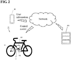
- FIG. 2 is a diagram illustrating a positional relationship between devices according to the first embodiment.
- an information terminal 50 transmits the user information to the server 200 via a network.
- the control device 100 receives the control model from the server 200.
- the control device 100 also obtains, from the torque sensor 11, the torque generated by the pedaling force of the user. Furthermore, the control device 100 obtains riding speed of the electric assist bicycle 10 from the speed sensor 12.
- the control device 100 controls the auxiliary power generated by the driving device 150 on the basis of the control model, the torque generated by the pedaling force of the user, and the riding speed.
- the control of auxiliary power will be described later.
- the control system 5 is a system that performs control in accordance with the athletic ability of the user by controlling the driving device 150 with use of a control model that corresponds to information about the user who uses the electric assist bicycle 10.
- control system 5 the control system 5 and the server 200 will be described separately.
- the information terminal 50 includes a user information obtaining unit 51, a storage unit 52, and a communication unit 53.
- the information terminal 50 is, for example, a mobile terminal such as a smartphone, a tablet PC, or a laptop PC.
- the components of the information terminal 50 can be realized by a CPU (processor) included in the information terminal 50 executing programs stored in the storage unit 52.
- the user information obtaining unit 51 obtains user information from the storage unit 52. Specifically, an application for transmitting a control request to the electric assist bicycle 10 is installed in the information terminal 50. When the user starts up the application, the information terminal 50 displays a log-in screen on a display (not shown). When log-in is executed, the user information obtaining unit 51 then obtains the user information of the user who logs in from the storage unit 52.
- the user information is information about the gender, age, height, weight, and the like of the user, that relate to the athletic ability of the user.
- the communication unit 53 transmits the user information obtained from the storage unit 52 to the server 200.
- the server 200 includes a communication unit 201, a model selection unit 202, and a storage unit 203.
- the communication unit 201 receives the user information from the information terminal 50.
- the model selection unit 202 obtains, from the storage unit 203, the control model corresponding to the user information received from the information terminal 50.
- the control models corresponding to the athletic ability levels of users are stored in the storage unit 203.
- the model selection unit 202 specifies the athletic ability level of the user on the basis of the information included in the user information, such as the gender, age, height, weight, and the like of the user.
- the model selection unit 202 selects the control model corresponding to the athletic ability level of the user out of the control models stored in the storage unit 203.
- FIGS. 3A and 3B are diagrams illustrating an example of the data structure of the table that holds the control models.
- FIG. 3A is an example of athletic ability levels of the users divided by gender, age, height, and weight of the user.
- the upper table of FIG. 3A relates to all the users, and is divided by age and gender.
- the rows in the upper table of FIG. 3A relate to gender, and male and female are associated with respective rows. Also, the columns in the upper table of FIG. 3A are each associated with different ages, namely 10s, 20s, 30s, and 40s. On the other hand, the lower table of FIG. 3A relates to males in their 20s, and this table corresponds to the section (3) in the upper table of FIG. 3A .
- the sections other than the section (3) namely, the sections (1), (2), (4) to (8) in the upper table of FIG. 3A are also associated with tables having the same structure as the section (3).
- the sections (9) to (24) in the lower table of FIG. 3A correspond to the athletic ability levels of males in their 20s.
- One control model is associated with each of the sections (9) to (24).
- the sections relating to all the users such as the sections (1) to (8) in the upper table of FIG. 3A , are called “large sections”.
- the sections relating to a part of the users in the large sections, such as the sections (9) to (24) in the lower table of FIG. 3A are called “small sections”.
- control model selection of the control model will be illustrated with a specific example.
- a case will be illustrated in which a 25-year-old man uses the electric assist bicycle 10.
- the server 200 obtains, via the communication unit 201, user information about the 25-year-old man who uses the electric assist bicycle 10.
- the model selection unit 202 obtains the age “25” and the gender "male”, from the user information. The model selection unit 202 then selects a large section (3) that corresponds to "age: 25” and "gender: male", out of the upper table of FIG. 3A .
- the model selection unit 202 then obtains the height "175" and the weight "67" of this user.
- the model selection unit 202 then selects the small section (18) out of the lower table of FIG. 3A that corresponds to the large section (3).
- the model selection unit 202 selects the control model corresponding to the small section (18).
- the model selection unit 202 selects the small section (9).
- the model selection unit 202 selects the small section (23).
- FIG. 3B is an example of athletic ability levels of the users divided on the basis of weight of the user.
- the table of FIG. 3B relates to all the users, and the sections are divided by weight.
- users in the 30-kg weight class (30-40 kg), 40-kg weight class, 50-kg weight class, 60-kg weight class, 70-kg weight class, 80-kg weight class, and 90-kg weight class are assigned the athletic ability levels (1) to (7), respectively.
- one control model is associated with each of the athletic ability levels (1) to (7).
- the athletic ability level includes only the weight.
- the ratio between the motive power and weight is called "power-weight ratio".
- power-weight ratio The ratio between the motive power and weight.
- fixing the power-weight ratio to 2.0 to 3.0 W/kg in accordance with the average value of the user makes it possible to select the control model in accordance with weight. With this configuration, the number of control models to be used can be reduced, and thus the control of the electric assist bicycle 10 can be simplified.
- control model is constituted by three parameters, namely, the torque ratio, an auxiliary power attenuation speed, and an auxiliary power stop speed.
- the torque ratio (Tm/Th) is the ratio between the torque (Tm) generated by the auxiliary power and the torque (Th) generated by pedaling force of the user.
- the auxiliary power is motive power that is generated by the driving device 150 that will be described later, and that assists riding the bike. The higher the torque ratio (Tm/Th) is, the user needs less effort to ride.
- the auxiliary power attenuation speed is a speed (km/h) at which attenuation of the torque ratio (Tm/Th) is started. The more the riding speed exceeds the auxiliary power attenuation speed, the greater attenuation amount of the torque ratio.
- the auxiliary power stop speed is a speed (km/h) at which the auxiliary power is stopped.
- the auxiliary power attenuation speed and the auxiliary power stop speed may also be set according to a standard defined by law, for example.
- the torque ratio is controlled to a certain value from a riding speed of 0 km/h up to the auxiliary power attenuation speed (km/h).
- the torque ratio is decreased gradually according to the excessive riding speed. Furthermore, when the riding speed of the electric assist bicycle 10 is increased and the speed of the electric assist bicycle 10 reaches the auxiliary power stop speed, the torque ratio is controlled to be 0. In other words, the torque ratio is controlled so as to be attenuated in proportion to the riding speed which exceeds the auxiliary power attenuation speed, and set to 0 when the riding speed reaches the auxiliary power stop speed.
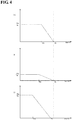
- FIGS. 4A to 4C are diagrams illustrating a relationship between the parameters of the control model.
- the vertical axes correspond to the torque ratio
- the horizontal axes correspond to the riding speed (km/h) of the electric assist bicycle 10.
- the torque ratio is denoted as Tm/Th
- the auxiliary power attenuation speed is denoted as Sm
- the auxiliary power stop speed is denoted as Sn.
- the torque ratio is an example of "the ratio related to the auxiliary power”.
- the auxiliary power attenuation speed is an example of "the threshold value of the speed at which the ratio related to the auxiliary power is decreased”.
- the auxiliary power stop speed is an example of "the threshold value of the speed at which the auxiliary power is stopped”.
- FIG. 4A shows an example of the control model used for a user with average athletic ability.
- the torque ratio (Tm/Th) is set to 1.0.
- the electric assist bicycle 10 assists the user with the same amount of torque (auxiliary power) as the torque (Tr) generated by the pedaling force of the user.
- the electric assist bicycle 10 sets the torque ratio (Tm/Th) to 0.
- the dotted lines in FIGS. 4A to 4C correspond to the auxiliary power attenuation speed Sm and the auxiliary power stop speed Sn that are set on the basis of the laws and regulations related to electric assist bicycles. In other words, in terms of laws and regulations, it is not possible to set the auxiliary power attenuation speed Sm and the auxiliary power stop speed Sn exceeding the dotted lines.
- FIG. 4B shows an example of the control model used for a user with comparatively high athletic ability.
- the torque ratio (Tm/Th) is set to 0.3. Suppressing the torque ratio to be lower than the example of FIG. 4A makes it possible to prevent a sudden acceleration.
- the auxiliary power attenuation speed Sm in the example of FIG. 4B is set lower than the auxiliary power attenuation speed Sm of the example of FIG. 4A . This configuration prevents the riding speed of an electric assist bicycle 10 from rising excessively.
- FIG. 4C shows a control model used for a user with comparatively low athletic ability, such as a child.
- FIG. 4C is, for example, a control model applied to the user at the age of 10 to 13.
- the torque ratio (Tm/Th) is set to 1.2. Setting the torque ratio higher than the example of FIG. 4A can increase the assistance when riding a sloping road, thus making it possible to reduce the user's load. Also, an unstable ride when riding at a low speed can be prevented.
- the auxiliary power attenuation speed Sm in the example of FIG. 4C is set lower than the auxiliary power attenuation speed Sm in the example of FIG. 4A .
- the assistance is decreased when riding at a high speed, thus making it possible to prevent an accident due to excessive speed.
- the auxiliary power stop speed Sn in the example of FIG. 4C is set lower than the auxiliary power stop speed Sn of the example of FIG. 4A .
- the assistance is stopped when riding at a speed at a predetermined speed or more, thus making it possible to prevent an accident due to excessive speed.
- the model selection unit 202 selects the control model corresponding to the athletic ability level of the user on the basis of the user information.
- the communication unit 201 then transmits the control model selected by the model selection unit 202 to the control device 100.
- the control device 100 includes a model obtaining unit 101, an auxiliary power control unit 102, and a storage unit 103.
- the model obtaining unit 101 obtains, from the server 200, the control model corresponding to the athletic ability level of the user that was selected by the server 200.
- the model obtaining unit 101 receives the control model selected by the model selection unit 202 from the server 200. The model obtaining unit 101 then records the selected control model in the storage unit 103 as a temporary file.
- the auxiliary power control unit 102 controls the auxiliary power generated by the driving device 150 on the basis of the control model.
- the auxiliary power control unit 102 obtains, from a torque sensor 11, the torque (Th) generated by the pedaling force of the user.
- the torque sensor 11 is a sensor that is installed in a pedal part of the electric assist bicycle 10 and detects the pressure applied to the pedal part due to the pedaling force of the user.
- the auxiliary power control unit 102 controls the driving device 150 such that the ratio between the torque (Th) generated by the pedaling force of the user and the torque (Tm) generated by the auxiliary power achieves the torque ratio (Tm/Th) defined as the control model.
- the torque ratio (Tm/Th) defined as the control model is 1.0, for example, the auxiliary power control unit 102 controls such that torque (Th) generated by the pedaling force of the user and the torque (Tm) generated by the auxiliary power are approximately the same.
- the auxiliary power control unit 102 may also calculate the torque (Tm) generated by the auxiliary power by multiplying the torque (Th) generated by the pedaling force of the user detected by the torque sensor 11 with the torque ratio (Tm/Th).
- the auxiliary power control unit 102 obtains the riding speed from the speed sensor 12. When the riding speed exceeds the auxiliary power attenuation speed Sm (Km/h), the auxiliary power control unit 102 controls the auxiliary power generated by the driving device 150 such that the torque ratio (Tm/Th) is attenuated in proportion to the excessive speed.
- the speed sensor 12 is a sensor for measuring a riding speed of the electric assist bicycle 10.
- the auxiliary power control unit 102 controls the auxiliary power generated by the driving device 150 such that the torque ratio (Tm/Th) becomes 0.
- the driving device 150 includes a driving control unit 151 and an output unit 152.
- the driving control unit 151 controls the drive outputted from the output unit 152 in accordance with the control performed by the auxiliary power control unit 102.
- the output unit 152 outputs the auxiliary power in accordance with the control performed by the drive control unit 151 to the electric assist bicycle 10.
- FIG. 5 is a diagram illustrating an example of a control flow executed by the control device 100 and the server 200 according to the first embodiment.
- the left flowchart of FIG. 5 illustrates the processes performed by the control system 5.
- the right flowchart of FIG. 5 illustrates the processes performed by the server 200.
- step S10 the control system 5 obtains the user information.
- the information terminal 50 performs log-in authentication, and obtains user information including the gender, age, height, weight of the user, from the storage unit 52.
- step S11 the control system 5 inquires the appropriate control model from the server 200 by transmitting the user information to the server 200.
- control system 5 may also directly request the control device 100 to input the user information, instead of the information terminal 50.
- server 200 repeatedly executes the processes from steps S20 to S22, and receives an inquiry from the control device 100 as needed.
- step S20 the server 200 determines whether an inquiry from the control system 5 has been received. If no inquiry has been received, the server 200 executes the process of step S20 again after a predetermined period of time.
- step S21 the server 200 selects the control model on the basis of the user information. If the table of FIG. 3A has been recorded in the storage unit 203, the server 200 selects a large section in the table of FIG. 3A on the basis of the age and gender of the user. Furthermore, the server 200 selects the control model by selecting a small section on the basis of the height and weight of the user. In step S22, the server 200 transmits the selected control model to the control system 5.
- step S12 the control system 5 determines whether the control model has been received. If no control model has been received, the control system 5 executes the process of step S12 again after a predetermined period of time. On the other hand, if a control model has been received, in step S13, the control system 5 reflects the control model on the control of the auxiliary power of the electric assist bicycle 10.
- the control system 5 controls the auxiliary power generated by the driving device 150 such that, for example, the ratio between the torque (Th) generated by the pedaling force of the user and the torque (Tm) generated by the auxiliary power achieves the torque ratio (Tm/Th) included in the control model.
- FIGS. 6A and 6B are diagrams for comparing the control according to the first embodiment with the control of a conventional example.
- FIG. 6A illustrates a control in a conventional example. As shown in FIG. 6A , one common control model is applied to male, female, and child users.
- the auxiliary power applied to the electric assist bicycle 10 is considerably insufficient, which may lead to an unstable ride when riding at a low speed.
- FIG. 6B illustrates the control according to the first embodiment. As shown in FIG. 6B , a control model that corresponds to the athletic ability level is applied to each of the male, female, and child users.
- the present invention is not limited thereto.
- a configuration is also possible in which the control model changes the torque ratio depending on the situation such as riding up a slope.
- a pressure sensor is installed in a saddle part of the electric assist bicycle 10 and whether the user is stand-pedaling can be determined by the pressure sensor.
- the control device 100 may also determine that the user is riding up a slope if the pressure sensor detects that the user is stand-pedaling.
- the auxiliary power control unit 102 controls the auxiliary power generated by the driving device 150 such that the torque ratio (Tm/Th) achieves the torque ratio (Tm/Th) for the case of a road face with a certain inclination.
- the control device 100 may also continue the same control until a predetermined period of time elapses even after the user sits on the saddle.
- the control model includes the torque ratio for the case of a flat road face and the torque ratio for the case of a road face with a certain inclination.
- the auxiliary power is controlled using the torque ratio for the flat road face.
- the auxiliary power control unit 102 controls the auxiliary power using the torque ratio for the case of a road face with a certain inclination. Accordingly, even when riding on a slope, the auxiliary power is controlled appropriately.
- control model having two kinds of torque ratios for a flat road face and a road face with a certain inclination was described as above, the control model is not limited thereto.
- the control device 100 may also use a control model having three or more torque ratios in accordance with the inclination angle of the road face.
- the control device 100 may also use a control model including torque ratios (Tm/Th) corresponding to the road face inclination angles of 0-degree, 5-degrees, 8-degrees, 12 degrees, and 15 degrees, and so on, respectively, for example. As the inclination angle increases, the torque ratio (Tm/Th) increases.
- torque ratio for inclination angle of 0 degrees ⁇ torque ratio for inclination angle of 5 degrees
- torque ratio for inclination angle of 8 degrees ⁇ torque ratio for inclination angle of 15 degrees
- the auxiliary power control unit 102 selects a torque ratio in accordance with the inclination of the road face that was measured by the inclination sensor, from the plurality of torque ratios included in the control model. The auxiliary power control unit 102 then controls the auxiliary power generated by the driving device 150 such that the torque ratio achieves the selected torque ratio.
- the auxiliary power control unit 102 may also control the auxiliary power using the control model having the torque ratio corresponding to the inclination angle of the road face. Accordingly, even when riding on a slope, the auxiliary power is controlled appropriately.
- the method for obtaining the inclination is not limited to using the inclination sensor.
- the auxiliary power control unit 102 may also obtain the current position using the GPS, and obtain the inclination of road face of the current position from map information, for example.
- the map information may be stored in a memory inside the control device 100, or received from an external server.
- FIG. 7 is a block diagram illustrating a functional configuration of a control system 20 according to a second embodiment.
- the control system 20 includes the information terminal 50 and a control device 300.
- the information terminal 50 has the same configuration as the information terminal 50 of the first embodiment.
- the information terminal 50 of this embodiment is different from that of the first embodiment in that a storage unit 303 has control models corresponding to the athletic ability levels of the users, instead of the control device 300 obtaining the control model by communicating with the server.
- FIGS. 3A and 3B illustrate an example of data structures for holding the control models in the storage unit 303.
- An application for transmitting a control request to the electric assist bicycle 10 is installed in the information terminal 50.
- the information terminal 50 displays a log-in screen on a display (not shown).
- the user information obtaining unit 51 obtains the user information from the storage unit 52. Examples of the user information include the gender, age, height, and weight of the user.
- the communication unit 53 then transmits the user information to the control device 300.
- a model obtaining unit 301 of the control device 300 specifies the athletic ability level of the user on the basis of the user information such as the gender, age, height, weight, and the like of the user.
- the model obtaining unit 301 selects the control model corresponding to the specified athletic ability level of the user.
- the model obtaining unit 301 records the selected control model in the storage region such as a RAM (not shown) as a temporary file.
- the control model includes the torque ratio (Tm/Th), the auxiliary power attenuation speed Sm (Km/h), the auxiliary power stop speed Sn (km/h), and the like, for example.
- An auxiliary power control unit 302 has a function of controlling the auxiliary power generated by a driving device 350 on the basis of the control model.
- the auxiliary power control unit 302 controls the driving device 350 such that the ratio between the torque (Th) generated by the pedaling force of the user and the torque (Tm) generated by the auxiliary power achieves the torque ratio (Tm/Th) defined as the control model.
- the auxiliary power control unit 302 controls the auxiliary power generated by the driving device 350 such that the torque ratio (Tm/Th) is attenuated in proportion to the excessive speed.
- the auxiliary power control unit 302 controls the auxiliary power generated by the driving device 350 such that the torque ratio (Tm/Th) becomes 0.
- the control device 100 may also have a function of the user information obtaining unit 51 of the information terminal 50.
- a configuration is also possible in which the display provided in the control device 100 receives a log-in operation, and the control device 100 obtains the information about the user of the electric assist bicycle 10 along with the log-in operation.
- the user information obtaining unit 51 obtains the user information from the storage unit 52
- the present invention is not limited thereto.
- the storage unit 203 of the server 200 may also store the user information of the users.
- the user information obtaining unit 51 may request the user to input log-in information such as the user ID and the password, and may transmit the input log-in information to the server 200.
- the user ID is identification information for uniquely identifying the user.
- the server 200 then obtains the user information stored in the storage unit 203 using the received user ID. Then, the model selection unit 202 specifies the athletic ability level of the user on the basis of the obtained information as the user information, such as the height, weight, age, gender, and the like. The model selection unit 202 then selects the control model corresponding to the athletic ability of the user out of the control models stored in the storage unit 203.
- the present invention can also be realized by a process in which a program that realizes one or more functions of the above embodiments is provided to a system or a device, and one or more processors in a computer in the system or device read out and execute the program. Also, the present invention can also be realized by means of a circuit (e.g. ASIC) that realizes one or more functions.
- a circuit e.g. ASIC
- a control system for controlling a driving device that generates auxiliary power for assisting a force that rotates a wheel of a bicycle comprising a hardware processor, wherein the hardware processor is configured to:
- a control method for controlling a driving device that generates auxiliary power for assisting a force that rotates a wheel of a bicycle comprising:
Abstract
Description
- The present invention relates to a technology for controlling a device that assists traveling by means of motive power.
- Businesses that allow multiple users to share electric assist bicycles have become popular. In an electric assist bicycle sharing business, for example, a user can borrow an electric assist bicycle at a station, and return the bicycle at another station. After that, the electric assist bicycle can be used again by another user near the station where the bicycle was returned. In this manner, one electric assist bicycle can be used repeatedly by various users, irrespective of gender and age.
- On the other hand, a technology is known in which auxiliary power for assisting riding an electric assist bicycle is controlled in accordance with conditions such as a riding speed and an inclination of a road face (e.g. Patent Document 1). The auxiliary power supplied when riding an electric assist bicycle can reduce the load on the user.
- Patent Document 1:
JP-A-2012-121338 - However, if the same control of auxiliary power is performed for all users, the auxiliary power may not be appropriate in some cases because athletic ability differs between the users.
- Assume, for example, a case in which the auxiliary power is set on the assumption that a user with average athletic ability uses the electric assist bicycle. In this case, if a user with low athletic ability uses the electric assist bicycle, the ride may be unstable because the auxiliary power is insufficient when riding up a slope. Conversely, if a user with high athletic ability uses the electric assist bicycle, the auxiliary power may be excessive, which may lead to accidents due to sudden acceleration.
- In other words, in the control of the auxiliary power, there is room for improvement in terms of that the athletic ability of users has not been considered.
- The present invention has been conceived in consideration with the above circumstances, and a purpose of the present invention is to provide a technology for controlling the auxiliary power in accordance with the athletic ability of the user who uses an electric assist bicycle.
- A control system according to the present invention is a control system for controlling a driving device that generates auxiliary power for assisting a force that rotates a wheel of a bicycle, the control system including:
- a user information obtaining unit configured to obtain information about a user of the bicycle;
- a model obtaining unit configured to obtain a control model used for controlling the auxiliary power, the control model corresponding to an athletic ability level of the user, on the basis of the user information, and
- an auxiliary power control unit configured to, on the basis of the obtained control model, control the auxiliary power generated by the driving device.
- The auxiliary power is motive power for assisting riding an electric assist bicycle, and is generated by a driving device. The auxiliary power is controlled by a control system in accordance with a control model.
- The control model is a reference used for controlling the auxiliary power generated by the driving device.
- The control model is set on the basis of the athletic ability level for each user. In other words, one control model is associated with the athletic ability level of one user. The control system specifies the athletic ability level of the user according to user information.
- User information is information about the athletic ability of the user. Examples of user information include the gender, age, height, and weight of the user.
- The user information obtaining unit may also obtain user information from a terminal such as a smartphone and a tablet PC, for example. Also, the user information obtaining unit may also obtain user information from a terminal installed in the electric assist bicycle.
- The control model includes a plurality of parameters.
- The control model may also include, for example, the ratio of the auxiliary power with respect to the load exerted by the user as the first parameter. Specifically, the control model may include the ratio (torque ratio) between the torque of pedaling force of the user and the torque of the auxiliary power. The control system controls such that the torque ratio between the torque of pedaling force of the user and the torque of the auxiliary power achieves a predetermined value.
- The torque ratio is set on the basis of the athletic ability level of the user, for example. The torque ratio for a user with high athletic ability can also be set to a comparatively low value, for example. Also, the torque ratio for a user with low athletic ability can also be set to a comparatively high value, for example. Note, that the torque ratio is set so as not to exceed a reference defined by law.
- Setting the torque ratio appropriately makes it possible to prevent sudden acceleration and unstable ride that may lead to an accident.
- The control model may also include, as a second parameter, a threshold value of a speed at which the ratio of the auxiliary power with respect to the load exerted by the user is decreased. Also, the control model may also include, as a third parameter, a threshold value of a speed at which the auxiliary power is stopped.
- The threshold value of a speed at which the ratio of the auxiliary power is decreased and the threshold value of a speed at which the auxiliary power is stopped may also be set according to a standard defined by law, for example. The threshold value of a speed at which the ratio of the auxiliary power is decreased and the threshold value of a speed at which the auxiliary power is stopped may also be changed according to the athletic ability level of the user.
- Setting the threshold value of a speed at which the ratio of the auxiliary power is decreased and the threshold value of a speed at which the auxiliary power is stopped according to the athletic ability level of the user makes it possible to prevent an accident caused by excessive speed and sudden acceleration.
- Note, that the control model may also include a parameter other than the above three parameters.
- The control model is set in accordance with athletic ability levels of the users. The athletic ability level is information divided by athletic ability of the user. The athletic ability level is specified by the user information.
- The athletic ability level may also include the weight of the user, for example. In this case, the control model is set by weight. In this case, the athletic ability level may be divided into weight ranges such as 30 to 40 kg, 40 to 50 kg, ..., 80 to 90 kg, 90 to 100 kg, for example, and one control model may also be set for each section.
- In this manner, dividing the control model by weight with fixing a power-weight ratio to a predetermined value makes it possible to reduce the number of the control models, and thus the control of the auxiliary power generated by the driving device can be simplified.
- The athletic ability level may also include the weight and height of the user. In such a case, the control model may also be set for each of a plurality of sections divided by weight and height.
- The athletic ability level may also include the gender and age of the user. In this case, the control model may also be set for each of a plurality of sections divided by gender and age.
- Additionally, the athletic ability level may also include the gender, age, weight and body height of the user. In this case, a configuration is also possible in which there are large sections divided by gender and age, and small sections further divided by height and weight, and the control model may also be set for each small section.
- This configuration makes it possible to divide the athletic ability level of the user in detail, and thus making it possible to more appropriately control the auxiliary power generated by the driving device.
- The model obtaining unit may also obtain, from an external server that stores a plurality of control models for respective athletic ability levels of the users, on the basis of the user information, a control model that corresponds to the athletic ability level of the user.
- Specifically, the storage region of the external server stores the control models corresponding to respective athletic ability levels. On the basis of the user information, the control model corresponding to the athletic ability level of the user is selected by the server.
- With this configuration, the control models need not be managed on the control system side, and it is possible to manage the control models collectively on the server side.
- Additionally, the control system may also further include a storage unit configured to store a plurality of control models for respective athletic ability levels of the users, and the model obtaining unit obtains, from the storage unit, on the basis of the user information, a control model that corresponds to the athletic ability level of the user. In this case, the control system does not communicate with an external server.
- This configuration makes it possible to control the auxiliary power without performing communication with the external server.
- A server that communicates with the control system according to the present invention may include: a user information obtaining unit configured to receive, from the control system according to any one of
claims 1 to 7, information about a user who uses a bicycle; a storage unit configured to store a plurality of control models for respective athletic ability levels of the users; a model selection unit configured to select, out of the control models stored in the storage unit, a control model that corresponds to athletic ability of the user, and a transmission unit configured to transmit the selected control model to the control system. - This configuration makes it possible to manage all the control models collectively on the server side.
- Note, that the present invention may be interpreted as a control system including at least part of the above configuration and function, or a vehicle provided with such control system. Furthermore, the present invention may also be interpreted as a method for controlling a vehicle that includes at least part of the above process. Furthermore, the present invention may also be interpreted as a program for causing a computer (processor) to execute the steps of the method, or a computer-readable recording medium that records the program in a non-transitory manner. Also, the above-described process and methods can be combined as needed and implemented as long as no technical contradiction occurs.
- According to the present invention, the auxiliary power can be controlled appropriately in accordance with the athletic ability of the user who uses the electric assist bicycle.
-
-
FIG. 1 is a block diagram illustrating a functional configuration of a control system according to a first embodiment of the present invention. -
FIG. 2 is a diagram illustrating a positional relationship between devices according to the first embodiment. -
FIGS. 3A and 3B are diagrams illustrating an example of data structure of a - table that holds control models.
-
FIGS. 4A to 4C are diagrams illustrating a relationship between parameters regarding the control models. -
FIG. 5 is a diagram illustrating an example of a control flow of a control device and a server according to the first embodiment. -
FIG. 6A is a diagram illustrating a control of a conventional example, andFIG. 6B is a diagram illustrating a control of the first embodiment. -
FIG. 7 is a block diagram illustrating a functional configuration of a control system according to a second embodiment of the present invention. - The present invention relates to the control of auxiliary power for a driving device that assists riding an electric assist bicycle.
-
FIG. 1 is a block diagram illustrating a functional configuration of acontrol system 5 according to a first embodiment. - The
control system 5 according to the first embodiment includes aninformation terminal 50 and acontrol device 100. The devices included in thecontrol system 5 can communicate with aserver 200. Atorque sensor 11, aspeed sensor 12, thecontrol device 100, and adriving device 150 are devices mounted on anelectric assist bicycle 10. - Note, that the
control device 100 can be constituted by an information processing apparatus including a CPU (a processor), a main storage device (a memory), an auxiliary storage device (e.g. a hard disk drive, a solid-state drive, a flash memory, or the like). Processes performed by thecontrol device 100 are executed by loading programs stored in the auxiliary storage device into the main storage device, and executing the programs by the CPU. -
FIG. 2 is a diagram illustrating a positional relationship between devices according to the first embodiment. As shown in the example ofFIG. 2 , aninformation terminal 50 transmits the user information to theserver 200 via a network. - The
control device 100 receives the control model from theserver 200. Thecontrol device 100 also obtains, from thetorque sensor 11, the torque generated by the pedaling force of the user. Furthermore, thecontrol device 100 obtains riding speed of theelectric assist bicycle 10 from thespeed sensor 12. - The
control device 100 controls the auxiliary power generated by the drivingdevice 150 on the basis of the control model, the torque generated by the pedaling force of the user, and the riding speed. The control of auxiliary power will be described later. - The description returns to
FIG. 1 . Thecontrol system 5 is a system that performs control in accordance with the athletic ability of the user by controlling thedriving device 150 with use of a control model that corresponds to information about the user who uses theelectric assist bicycle 10. - Hereinafter, the configuration of the
control system 5 and theserver 200 will be described separately. - The
information terminal 50 includes a userinformation obtaining unit 51, astorage unit 52, and acommunication unit 53. Theinformation terminal 50 is, for example, a mobile terminal such as a smartphone, a tablet PC, or a laptop PC. Note, that the components of theinformation terminal 50 can be realized by a CPU (processor) included in theinformation terminal 50 executing programs stored in thestorage unit 52. - The user
information obtaining unit 51 obtains user information from thestorage unit 52. Specifically, an application for transmitting a control request to theelectric assist bicycle 10 is installed in theinformation terminal 50. When the user starts up the application, theinformation terminal 50 displays a log-in screen on a display (not shown). When log-in is executed, the userinformation obtaining unit 51 then obtains the user information of the user who logs in from thestorage unit 52. Here, the user information is information about the gender, age, height, weight, and the like of the user, that relate to the athletic ability of the user. - After that, the
communication unit 53 transmits the user information obtained from thestorage unit 52 to theserver 200. - The
server 200 includes acommunication unit 201, amodel selection unit 202, and astorage unit 203. Thecommunication unit 201 receives the user information from theinformation terminal 50. - The
model selection unit 202 obtains, from thestorage unit 203, the control model corresponding to the user information received from theinformation terminal 50. The control models corresponding to the athletic ability levels of users are stored in thestorage unit 203. - The
model selection unit 202 specifies the athletic ability level of the user on the basis of the information included in the user information, such as the gender, age, height, weight, and the like of the user. Themodel selection unit 202 selects the control model corresponding to the athletic ability level of the user out of the control models stored in thestorage unit 203. - The structure of a table that holds the control models in the
storage unit 203 will be described. -
FIGS. 3A and 3B are diagrams illustrating an example of the data structure of the table that holds the control models.FIG. 3A is an example of athletic ability levels of the users divided by gender, age, height, and weight of the user. The upper table ofFIG. 3A relates to all the users, and is divided by age and gender. - The rows in the upper table of
FIG. 3A relate to gender, and male and female are associated with respective rows. Also, the columns in the upper table ofFIG. 3A are each associated with different ages, namely 10s, 20s, 30s, and 40s. On the other hand, the lower table ofFIG. 3A relates to males in their 20s, and this table corresponds to the section (3) in the upper table ofFIG. 3A . - Although not illustrated, the sections other than the section (3), namely, the sections (1), (2), (4) to (8) in the upper table of
FIG. 3A are also associated with tables having the same structure as the section (3). The sections (9) to (24) in the lower table ofFIG. 3A correspond to the athletic ability levels of males in their 20s. One control model is associated with each of the sections (9) to (24). - Hereinafter, the sections relating to all the users, such as the sections (1) to (8) in the upper table of
FIG. 3A , are called "large sections". The sections relating to a part of the users in the large sections, such as the sections (9) to (24) in the lower table ofFIG. 3A , are called "small sections". - Hereinafter, selection of the control model will be illustrated with a specific example. A case will be illustrated in which a 25-year-old man uses the
electric assist bicycle 10. Theserver 200 obtains, via thecommunication unit 201, user information about the 25-year-old man who uses theelectric assist bicycle 10. - The
model selection unit 202 obtains the age "25" and the gender "male", from the user information. Themodel selection unit 202 then selects a large section (3) that corresponds to "age: 25" and "gender: male", out of the upper table ofFIG. 3A . - The
model selection unit 202 then obtains the height "175" and the weight "67" of this user. Themodel selection unit 202 then selects the small section (18) out of the lower table ofFIG. 3A that corresponds to the large section (3). Next, themodel selection unit 202 selects the control model corresponding to the small section (18). - If the height of a male user in his 20s is "161" and the weight is "49", the
model selection unit 202 selects the small section (9). - If the height of a male user in his 20s is "183" and the weight is "75", the
model selection unit 202 selects the small section (23). -
FIG. 3B is an example of athletic ability levels of the users divided on the basis of weight of the user. The table ofFIG. 3B relates to all the users, and the sections are divided by weight. In the example ofFIG. 3B , users in the 30-kg weight class (30-40 kg), 40-kg weight class, 50-kg weight class, 60-kg weight class, 70-kg weight class, 80-kg weight class, and 90-kg weight class are assigned the athletic ability levels (1) to (7), respectively. Also, one control model is associated with each of the athletic ability levels (1) to (7). - Specifically, in the example of
FIG. 3B , the athletic ability level includes only the weight. - The ratio between the motive power and weight is called "power-weight ratio". In the example of
FIG. 3B , for example, fixing the power-weight ratio to 2.0 to 3.0 W/kg in accordance with the average value of the user makes it possible to select the control model in accordance with weight. With this configuration, the number of control models to be used can be reduced, and thus the control of theelectric assist bicycle 10 can be simplified. - Next, the configuration of each control model will be described.
- In first embodiment, the control model is constituted by three parameters, namely, the torque ratio, an auxiliary power attenuation speed, and an auxiliary power stop speed.
- The torque ratio (Tm/Th) is the ratio between the torque (Tm) generated by the auxiliary power and the torque (Th) generated by pedaling force of the user. The auxiliary power is motive power that is generated by the driving
device 150 that will be described later, and that assists riding the bike. The higher the torque ratio (Tm/Th) is, the user needs less effort to ride. - The auxiliary power attenuation speed is a speed (km/h) at which attenuation of the torque ratio (Tm/Th) is started. The more the riding speed exceeds the auxiliary power attenuation speed, the greater attenuation amount of the torque ratio. The auxiliary power stop speed is a speed (km/h) at which the auxiliary power is stopped. The auxiliary power attenuation speed and the auxiliary power stop speed may also be set according to a standard defined by law, for example.
- Next, the relationship between the above three parameters will be described. The torque ratio is controlled to a certain value from a riding speed of 0 km/h up to the auxiliary power attenuation speed (km/h).
- When the riding speed of the
electric assist bicycle 10 increases and exceeds the auxiliary power attenuation speed, the torque ratio is decreased gradually according to the excessive riding speed. Furthermore, when the riding speed of theelectric assist bicycle 10 is increased and the speed of theelectric assist bicycle 10 reaches the auxiliary power stop speed, the torque ratio is controlled to be 0. In other words, the torque ratio is controlled so as to be attenuated in proportion to the riding speed which exceeds the auxiliary power attenuation speed, and set to 0 when the riding speed reaches the auxiliary power stop speed. - The relationship between the above three parameters will be described with specific examples.
-
FIGS. 4A to 4C are diagrams illustrating a relationship between the parameters of the control model. InFIGS. 4A to 4C , the vertical axes correspond to the torque ratio, and the horizontal axes correspond to the riding speed (km/h) of theelectric assist bicycle 10. Also, the torque ratio is denoted as Tm/Th, the auxiliary power attenuation speed is denoted as Sm, and the auxiliary power stop speed is denoted as Sn. - Note, that the torque ratio is an example of "the ratio related to the auxiliary power". Also, the auxiliary power attenuation speed is an example of "the threshold value of the speed at which the ratio related to the auxiliary power is decreased". Also, the auxiliary power stop speed is an example of "the threshold value of the speed at which the auxiliary power is stopped".
-
FIG. 4A shows an example of the control model used for a user with average athletic ability. In the example ofFIG. 4A , the torque ratio (Tm/Th) is set to 1.0. In other words, theelectric assist bicycle 10 assists the user with the same amount of torque (auxiliary power) as the torque (Tr) generated by the pedaling force of the user. - Also, once the riding speed (Km/h) exceeds the auxiliary power attenuation speed Sm, the
electric assist bicycle 10 gradually attenuates the torque ratio (Tm/Th). - Furthermore, when the riding speed (km/h) reaches the auxiliary power stop speed, the
electric assist bicycle 10 sets the torque ratio (Tm/Th) to 0. - Note, that the dotted lines in
FIGS. 4A to 4C correspond to the auxiliary power attenuation speed Sm and the auxiliary power stop speed Sn that are set on the basis of the laws and regulations related to electric assist bicycles. In other words, in terms of laws and regulations, it is not possible to set the auxiliary power attenuation speed Sm and the auxiliary power stop speed Sn exceeding the dotted lines. -
FIG. 4B shows an example of the control model used for a user with comparatively high athletic ability. In the example ofFIG. 4B , the torque ratio (Tm/Th) is set to 0.3. Suppressing the torque ratio to be lower than the example ofFIG. 4A makes it possible to prevent a sudden acceleration. - The auxiliary power attenuation speed Sm in the example of
FIG. 4B is set lower than the auxiliary power attenuation speed Sm of the example ofFIG. 4A . This configuration prevents the riding speed of anelectric assist bicycle 10 from rising excessively. -
FIG. 4C shows a control model used for a user with comparatively low athletic ability, such as a child.FIG. 4C is, for example, a control model applied to the user at the age of 10 to 13. In the example ofFIG. 4C , the torque ratio (Tm/Th) is set to 1.2. Setting the torque ratio higher than the example ofFIG. 4A can increase the assistance when riding a sloping road, thus making it possible to reduce the user's load. Also, an unstable ride when riding at a low speed can be prevented. - The auxiliary power attenuation speed Sm in the example of
FIG. 4C is set lower than the auxiliary power attenuation speed Sm in the example ofFIG. 4A . With this configuration, the assistance is decreased when riding at a high speed, thus making it possible to prevent an accident due to excessive speed. - Also, the auxiliary power stop speed Sn in the example of
FIG. 4C is set lower than the auxiliary power stop speed Sn of the example ofFIG. 4A . With this configuration, the assistance is stopped when riding at a speed at a predetermined speed or more, thus making it possible to prevent an accident due to excessive speed. - As described above, the
model selection unit 202 selects the control model corresponding to the athletic ability level of the user on the basis of the user information. Thecommunication unit 201 then transmits the control model selected by themodel selection unit 202 to thecontrol device 100. - The description returns to
FIG. 1 . Thecontrol device 100 includes amodel obtaining unit 101, an auxiliarypower control unit 102, and astorage unit 103. Themodel obtaining unit 101 obtains, from theserver 200, the control model corresponding to the athletic ability level of the user that was selected by theserver 200. - The
model obtaining unit 101 receives the control model selected by themodel selection unit 202 from theserver 200. Themodel obtaining unit 101 then records the selected control model in thestorage unit 103 as a temporary file. - The auxiliary
power control unit 102 controls the auxiliary power generated by the drivingdevice 150 on the basis of the control model. The auxiliarypower control unit 102 obtains, from atorque sensor 11, the torque (Th) generated by the pedaling force of the user. Thetorque sensor 11 is a sensor that is installed in a pedal part of theelectric assist bicycle 10 and detects the pressure applied to the pedal part due to the pedaling force of the user. - The auxiliary
power control unit 102 controls thedriving device 150 such that the ratio between the torque (Th) generated by the pedaling force of the user and the torque (Tm) generated by the auxiliary power achieves the torque ratio (Tm/Th) defined as the control model. When the torque ratio (Tm/Th) defined as the control model is 1.0, for example, the auxiliarypower control unit 102 controls such that torque (Th) generated by the pedaling force of the user and the torque (Tm) generated by the auxiliary power are approximately the same. - In other words, the auxiliary
power control unit 102 may also calculate the torque (Tm) generated by the auxiliary power by multiplying the torque (Th) generated by the pedaling force of the user detected by thetorque sensor 11 with the torque ratio (Tm/Th). - Also, the auxiliary
power control unit 102 obtains the riding speed from thespeed sensor 12. When the riding speed exceeds the auxiliary power attenuation speed Sm (Km/h), the auxiliarypower control unit 102 controls the auxiliary power generated by the drivingdevice 150 such that the torque ratio (Tm/Th) is attenuated in proportion to the excessive speed. Note, that thespeed sensor 12 is a sensor for measuring a riding speed of theelectric assist bicycle 10. - Furthermore, when the riding speed reaches the auxiliary power stop speed Sn (km/h), the auxiliary
power control unit 102 controls the auxiliary power generated by the drivingdevice 150 such that the torque ratio (Tm/Th) becomes 0. - The
driving device 150 includes a drivingcontrol unit 151 and anoutput unit 152. The drivingcontrol unit 151 controls the drive outputted from theoutput unit 152 in accordance with the control performed by the auxiliarypower control unit 102. Theoutput unit 152 outputs the auxiliary power in accordance with the control performed by thedrive control unit 151 to theelectric assist bicycle 10. -
FIG. 5 is a diagram illustrating an example of a control flow executed by thecontrol device 100 and theserver 200 according to the first embodiment. The left flowchart ofFIG. 5 illustrates the processes performed by thecontrol system 5. On the other hand, the right flowchart ofFIG. 5 illustrates the processes performed by theserver 200. - In step S10, the
control system 5 obtains the user information. After the user starts up the application, for example, theinformation terminal 50 performs log-in authentication, and obtains user information including the gender, age, height, weight of the user, from thestorage unit 52. In step S11, thecontrol system 5 inquires the appropriate control model from theserver 200 by transmitting the user information to theserver 200. - Alternatively, the
control system 5 may also directly request thecontrol device 100 to input the user information, instead of theinformation terminal 50. - Note, that the
server 200 repeatedly executes the processes from steps S20 to S22, and receives an inquiry from thecontrol device 100 as needed. - In step S20, the
server 200 determines whether an inquiry from thecontrol system 5 has been received. If no inquiry has been received, theserver 200 executes the process of step S20 again after a predetermined period of time. - On the other hand, if an inquiry has been received, in step S21, the
server 200 selects the control model on the basis of the user information. If the table ofFIG. 3A has been recorded in thestorage unit 203, theserver 200 selects a large section in the table ofFIG. 3A on the basis of the age and gender of the user. Furthermore, theserver 200 selects the control model by selecting a small section on the basis of the height and weight of the user. In step S22, theserver 200 transmits the selected control model to thecontrol system 5. - In step S12, the
control system 5 determines whether the control model has been received. If no control model has been received, thecontrol system 5 executes the process of step S12 again after a predetermined period of time. On the other hand, if a control model has been received, in step S13, thecontrol system 5 reflects the control model on the control of the auxiliary power of theelectric assist bicycle 10. - The
control system 5 controls the auxiliary power generated by the drivingdevice 150 such that, for example, the ratio between the torque (Th) generated by the pedaling force of the user and the torque (Tm) generated by the auxiliary power achieves the torque ratio (Tm/Th) included in the control model. -
FIGS. 6A and 6B are diagrams for comparing the control according to the first embodiment with the control of a conventional example. -
FIG. 6A illustrates a control in a conventional example. As shown inFIG. 6A , one common control model is applied to male, female, and child users. - It is assumed that, for example, when a male user with comparatively high athletic ability uses the
electric assist bicycle 10, the auxiliary power applied to theelectric assist bicycle 10 is appropriate. - As such, when a female user with average athletic ability uses the
electric assist bicycle 10, the auxiliary power applied to theelectric assist bicycle 10 is somewhat insufficient, and thus a load on the user increases when riding at a low speed. - When a child user with comparatively low athletic ability uses the
electric assist bicycle 10, the auxiliary power applied to theelectric assist bicycle 10 is considerably insufficient, which may lead to an unstable ride when riding at a low speed. -
FIG. 6B illustrates the control according to the first embodiment. As shown inFIG. 6B , a control model that corresponds to the athletic ability level is applied to each of the male, female, and child users. - When a male user with comparatively high athletic ability uses the
electric assist bicycle 10, for example, a control model in which the torque ratio is comparatively low is applied to theelectric assist bicycle 10. By doing this, a sudden acceleration due to excessive auxiliary power can be prevented. - When a female user with average athletic ability uses the
electric assist bicycle 10, a control model in which the torque ratio is moderate is applied to theelectric assist bicycle 10. By doing this, the load during traveling can be reduced. - When a child user with comparatively low athletic ability uses the
electric assist bicycle 10, for example, a control model in which the torque ratio is comparatively high is applied to theelectric assist bicycle 10. By doing this, unstable driving due to lack of the auxiliary power can be prevented. - In this manner, using the control model in accordance with the athletic ability of the user who uses the
electric assist bicycle 10 makes it possible to control the auxiliary power generated by the driving device appropriately, thus making it possible to reduce the load on the user during traveling. Additionally, an accident caused by a sudden acceleration or unstable driving can be prevented. - Although the first embodiment describes the torque ratio (Tm/Th) being controlled to a certain value by the control model at a low speed, the present invention is not limited thereto. A configuration is also possible in which the control model changes the torque ratio depending on the situation such as riding up a slope.
- Here, a case will be described in which three parameters (e.g. the torque ratio) are given to one control model for each of the case of a flat road face and the case of a road face with a certain inclination.
- Assume, for example, that a pressure sensor is installed in a saddle part of the
electric assist bicycle 10 and whether the user is stand-pedaling can be determined by the pressure sensor. Thecontrol device 100 may also determine that the user is riding up a slope if the pressure sensor detects that the user is stand-pedaling. - In this case, the auxiliary
power control unit 102 controls the auxiliary power generated by the drivingdevice 150 such that the torque ratio (Tm/Th) achieves the torque ratio (Tm/Th) for the case of a road face with a certain inclination. Thecontrol device 100 may also continue the same control until a predetermined period of time elapses even after the user sits on the saddle. - In the other words, the control model includes the torque ratio for the case of a flat road face and the torque ratio for the case of a road face with a certain inclination. In this case, when the user is sitting on the saddle, the auxiliary power is controlled using the torque ratio for the flat road face. When the user is not sitting on the saddle, the auxiliary
power control unit 102 controls the auxiliary power using the torque ratio for the case of a road face with a certain inclination. Accordingly, even when riding on a slope, the auxiliary power is controlled appropriately. - Although an example of the control model having two kinds of torque ratios for a flat road face and a road face with a certain inclination was described as above, the control model is not limited thereto. The
control device 100 may also use a control model having three or more torque ratios in accordance with the inclination angle of the road face. - The
control device 100 may also use a control model including torque ratios (Tm/Th) corresponding to the road face inclination angles of 0-degree, 5-degrees, 8-degrees, 12 degrees, and 15 degrees, and so on, respectively, for example. As the inclination angle increases, the torque ratio (Tm/Th) increases. - In other words, the following relationship is satisfied;
torque ratio for inclination angle of 0 degrees < torque ratio for inclination angle of 5 degrees < torque ratio for inclination angle of 8 degrees < torque ratio for inclination angle of 15 degrees - Assume, for example, a case in which the
electric assist bicycle 10 is provided with an inclination sensor, which enables measurement of the inclination of the road face. In this case, the auxiliarypower control unit 102 selects a torque ratio in accordance with the inclination of the road face that was measured by the inclination sensor, from the plurality of torque ratios included in the control model. The auxiliarypower control unit 102 then controls the auxiliary power generated by the drivingdevice 150 such that the torque ratio achieves the selected torque ratio. - In other words, the auxiliary
power control unit 102 may also control the auxiliary power using the control model having the torque ratio corresponding to the inclination angle of the road face. Accordingly, even when riding on a slope, the auxiliary power is controlled appropriately. - Note, that the method for obtaining the inclination is not limited to using the inclination sensor. The auxiliary
power control unit 102 may also obtain the current position using the GPS, and obtain the inclination of road face of the current position from map information, for example. Also, the map information may be stored in a memory inside thecontrol device 100, or received from an external server. -
FIG. 7 is a block diagram illustrating a functional configuration of acontrol system 20 according to a second embodiment. Thecontrol system 20 includes theinformation terminal 50 and acontrol device 300. Theinformation terminal 50 has the same configuration as theinformation terminal 50 of the first embodiment. - The
information terminal 50 of this embodiment is different from that of the first embodiment in that astorage unit 303 has control models corresponding to the athletic ability levels of the users, instead of thecontrol device 300 obtaining the control model by communicating with the server. - Note, that
FIGS. 3A and 3B illustrate an example of data structures for holding the control models in thestorage unit 303. - An application for transmitting a control request to the
electric assist bicycle 10 is installed in theinformation terminal 50. When a user who uses theelectric assist bicycle 30 starts up the application, theinformation terminal 50 displays a log-in screen on a display (not shown). When log-in is executed, the userinformation obtaining unit 51 then obtains the user information from thestorage unit 52. Examples of the user information include the gender, age, height, and weight of the user. - The
communication unit 53 then transmits the user information to thecontrol device 300. - Then, a
model obtaining unit 301 of thecontrol device 300 specifies the athletic ability level of the user on the basis of the user information such as the gender, age, height, weight, and the like of the user. Themodel obtaining unit 301 selects the control model corresponding to the specified athletic ability level of the user. Next, themodel obtaining unit 301 records the selected control model in the storage region such as a RAM (not shown) as a temporary file. - The control model includes the torque ratio (Tm/Th), the auxiliary power attenuation speed Sm (Km/h), the auxiliary power stop speed Sn (km/h), and the like, for example.
- An auxiliary
power control unit 302 has a function of controlling the auxiliary power generated by adriving device 350 on the basis of the control model. The auxiliarypower control unit 302 controls thedriving device 350 such that the ratio between the torque (Th) generated by the pedaling force of the user and the torque (Tm) generated by the auxiliary power achieves the torque ratio (Tm/Th) defined as the control model. - When the riding speed exceeds the auxiliary power attenuation speed Sm (Km/h), the auxiliary
power control unit 302 controls the auxiliary power generated by the drivingdevice 350 such that the torque ratio (Tm/Th) is attenuated in proportion to the excessive speed. - Furthermore, when the riding speed reaches the auxiliary power stop speed Sn (km/h), the auxiliary
power control unit 302 controls the auxiliary power generated by the drivingdevice 350 such that the torque ratio (Tm/Th) becomes 0. - In this manner, storing the control models in the
storage unit 303 in thecontrol device 300 makes it possible to apply the control model corresponding to the athletic ability of the user regardless the communication environment. - Note, that the descriptions of the embodiments are examples for illustrating the present invention, and the present invention can be implemented by modifying or combining such embodiments as appropriate without departing from the spirit of the present invention.
- The
control device 100, for example, may also have a function of the userinformation obtaining unit 51 of theinformation terminal 50. In other words, a configuration is also possible in which the display provided in thecontrol device 100 receives a log-in operation, and thecontrol device 100 obtains the information about the user of theelectric assist bicycle 10 along with the log-in operation. - Although the above embodiments describe that the user
information obtaining unit 51 obtains the user information from thestorage unit 52, the present invention is not limited thereto. In the first embodiment, for example, thestorage unit 203 of theserver 200 may also store the user information of the users. - Specifically, the user
information obtaining unit 51 may request the user to input log-in information such as the user ID and the password, and may transmit the input log-in information to theserver 200. The user ID is identification information for uniquely identifying the user. - If the log-in information is correct, the
server 200 then obtains the user information stored in thestorage unit 203 using the received user ID. Then, themodel selection unit 202 specifies the athletic ability level of the user on the basis of the obtained information as the user information, such as the height, weight, age, gender, and the like. Themodel selection unit 202 then selects the control model corresponding to the athletic ability of the user out of the control models stored in thestorage unit 203. - The present invention can also be realized by a process in which a program that realizes one or more functions of the above embodiments is provided to a system or a device, and one or more processors in a computer in the system or device read out and execute the program. Also, the present invention can also be realized by means of a circuit (e.g. ASIC) that realizes one or more functions.
- A control system for controlling a driving device that generates auxiliary power for assisting a force that rotates a wheel of a bicycle, the control system comprising a hardware processor,
wherein the hardware processor is configured to: - obtain information about a user of the bicycle;
- obtain, on the basis of the user information, a control model that is used for controlling the auxiliary power and corresponds to the athletic ability level of the user, and
- control, on the basis of the obtained control model, the auxiliary power generated by the driving device.
- A control method for controlling a driving device that generates auxiliary power for assisting a force that rotates a wheel of a bicycle, the control method comprising:
- a step of obtaining, by at least one hardware processor, information about a user of the bicycle,
- a step of obtaining, by at least one hardware processor, on the basis of the user information, a control model that is used for controlling the auxiliary power and corresponds to the athletic ability level of the user, and
- a step of controlling, by at least one hardware processor, on the basis of the obtained control model, the auxiliary power generated by the driving device.
-
- 5
- Control system
- 10
- Electric assist bicycle
- 11
- Torque sensor
- 50
- Information terminal
- 51
- User information obtaining unit
- 52
- Storage unit
- 53
- Communication unit
- 100
- Control device
- 101
- Model obtaining unit
- 102
- Auxiliary power control unit
- 103
- Storage unit
- 150
- Driving device
- 151
- Drive control unit
- 152
- Output unit
Claims (10)
- A control system for controlling a driving device that generates auxiliary power for assisting a force that rotates a wheel of a bicycle, the control system comprising:a user information obtaining unit configured to obtain information about a user of the bicycle;a model obtaining unit configured to obtain a control model used for controlling the auxiliary power, the control model corresponding to an athletic ability level of the user, on the basis of the user information, andan auxiliary power control unit configured to, on the basis of the obtained control model, control the auxiliary power generated by the driving device.
- The control system according to claim 1,
wherein the model obtaining unit obtains, from an external server that stores a plurality of control models for respective athletic ability levels of the users, on the basis of the user information, a control model that corresponds to the athletic ability level of the user. - The control system according to claim 1, further comprising
a storage unit configured to store a plurality of control models for respective athletic ability levels of the users,
wherein the model obtaining unit obtains, from the storage unit, on the basis of the user information, a control model that corresponds to the athletic ability level of the user. - The control system according to any one of claims 1 to 3, wherein the control model includes a ratio of the auxiliary power to a load exerted by the user.
- The control system according to any one of claims 1 to 4,
wherein the athletic ability level includes the weight of the user, and
the control model is set by weight. - The control system according to any one of claims 1 to 5,
wherein the athletic ability level includes the weight and height of the user, and
the control model is set for each of a plurality of sections divided by weight and height. - The control system according to any one of claims 1 to 6,
wherein the athletic ability level includes the gender and age of the user, and
the control model is set for each of a plurality of sections divided by gender and age. - A server comprising:a user information obtaining unit configured to receive, from the control system according to any one of claims 1 to 7, information about a user who uses a bicycle;a storage unit configured to store a plurality of control models for respective athletic ability levels of the users;a model selection unit configured to select, out of the control models stored in the storage unit, a control model that corresponds to athletic ability of the user, anda transmission unit configured to transmit the selected control model to the control system.
- A control method comprising:a step of obtaining information about a user of a bicycle;a step of obtaining, on the basis of the user information, a control model used for controlling auxiliary power generated by a driving device for assisting a force that rotates a wheel of the bicycle, a control model corresponding to an athletic ability level of the user, anda step of controlling, on the basis of the obtained control model, the auxiliary power generated by the driving device.
- A program for causing a computer to execute the steps of the control method according to claim 9.
Applications Claiming Priority (2)
| Application Number | Priority Date | Filing Date | Title |
|---|---|---|---|
| JP2016199899A JP2018062195A (en) | 2016-10-11 | 2016-10-11 | Control system, control method, and program |
| PCT/JP2017/034736 WO2018070235A1 (en) | 2016-10-11 | 2017-09-26 | Control system, server, control method, and program |
Publications (2)
| Publication Number | Publication Date |
|---|---|
| EP3527475A1 true EP3527475A1 (en) | 2019-08-21 |
| EP3527475A4 EP3527475A4 (en) | 2020-01-08 |
Family
ID=61905593
Family Applications (1)
| Application Number | Title | Priority Date | Filing Date |
|---|---|---|---|
| EP17860686.9A Withdrawn EP3527475A4 (en) | 2016-10-11 | 2017-09-26 | Control system, server, control method, and program |
Country Status (5)
| Country | Link |
|---|---|
| US (1) | US20210284278A1 (en) |
| EP (1) | EP3527475A4 (en) |
| JP (1) | JP2018062195A (en) |
| CN (1) | CN109689490A (en) |
| WO (1) | WO2018070235A1 (en) |
Families Citing this family (4)
| Publication number | Priority date | Publication date | Assignee | Title |
|---|---|---|---|---|
| JP7125889B2 (en) * | 2018-04-27 | 2022-08-25 | 株式会社シマノ | Manpowered vehicle controller |
| DE102021121417A1 (en) * | 2020-08-31 | 2022-03-03 | Shimano Inc. | CONTROL DEVICE FOR A HUMAN-PROPELLED VEHICLE, CONTROL SYSTEM FOR A HUMAN-PROPELLED VEHICLE, AND METHOD FOR ADJUSTING THE CONTROL STATE OF THE CONTROL DEVICE |
| DE102021209297A1 (en) | 2021-08-25 | 2023-03-02 | Robert Bosch Gesellschaft mit beschränkter Haftung | Control system for an electric bicycle |
| TWI779849B (en) * | 2021-09-28 | 2022-10-01 | 和碩聯合科技股份有限公司 | Electric auxiliary bicycle system and electric auxiliary bicycle |
Family Cites Families (16)
| Publication number | Priority date | Publication date | Assignee | Title |
|---|---|---|---|---|
| JP3276420B2 (en) * | 1992-09-30 | 2002-04-22 | ヤマハ発動機株式会社 | Bicycle with electric motor |
| TW409105B (en) * | 1997-07-22 | 2000-10-21 | Honda Motor Co Ltd | Auxiliary power control unit for auxiliary electromotive bicycle |
| JP2004345400A (en) * | 2003-05-20 | 2004-12-09 | Sony Corp | Electric power assist bicycle |
| JP2007145277A (en) * | 2005-11-30 | 2007-06-14 | Matsushita Electric Ind Co Ltd | Electric-assisted bicycle |
| JP2008143330A (en) * | 2006-12-08 | 2008-06-26 | Bridgestone Corp | Driving force control device for electrically assisted bicycle and electrically assisted bicycle |
| JP5049042B2 (en) * | 2007-04-05 | 2012-10-17 | サンスター技研株式会社 | Electric assist bicycle |
| US20090181826A1 (en) * | 2008-01-14 | 2009-07-16 | Turner James R | Electric bicycle with personal digital assistant |
| JP5305513B2 (en) * | 2008-12-26 | 2013-10-02 | パナソニック株式会社 | Electric assist vehicle control system |
| JP2011168241A (en) * | 2010-02-22 | 2011-09-01 | Panasonic Corp | Electric power-assisted bicycle |
| JP5570248B2 (en) * | 2010-03-03 | 2014-08-13 | 株式会社東京アールアンドデー | Electric assist control method and electric assist bicycle |
| JP5418512B2 (en) * | 2011-01-18 | 2014-02-19 | 株式会社デンソー | Two-wheeled vehicle, two-wheeled vehicle posture stabilization device and two-wheeled vehicle posture stabilization method |
| CN203528738U (en) * | 2013-08-30 | 2014-04-09 | 孙敏 | Electric assisting bicycle drive system capable of recognizing road states |
| JP5882400B2 (en) * | 2014-02-04 | 2016-03-09 | ヤマハ発動機株式会社 | Electric auxiliary vehicle and assist ratio control device |
| KR20170038837A (en) * | 2014-08-05 | 2017-04-07 | 폴브룩 인텔렉츄얼 프로퍼티 컴퍼니 엘엘씨 | Components, systems and methods of bicycle-based network connectivity and methods for controlling a bicycle having network connectivity |
| JP5941120B2 (en) * | 2014-10-31 | 2016-06-29 | 株式会社シマノ | Bicycle control device |
| TWM520498U (en) * | 2015-11-06 | 2016-04-21 | 國立成功大學 | Continuously variable transmission system and bycyle using the same |
-
2016
- 2016-10-11 JP JP2016199899A patent/JP2018062195A/en active Pending
-
2017
- 2017-09-26 WO PCT/JP2017/034736 patent/WO2018070235A1/en active Search and Examination
- 2017-09-26 US US16/332,406 patent/US20210284278A1/en not_active Abandoned
- 2017-09-26 EP EP17860686.9A patent/EP3527475A4/en not_active Withdrawn
- 2017-09-26 CN CN201780055224.4A patent/CN109689490A/en active Pending
Also Published As
| Publication number | Publication date |
|---|---|
| EP3527475A4 (en) | 2020-01-08 |
| JP2018062195A (en) | 2018-04-19 |
| WO2018070235A1 (en) | 2018-04-19 |
| CN109689490A (en) | 2019-04-26 |
| US20210284278A1 (en) | 2021-09-16 |
Similar Documents
| Publication | Publication Date | Title |
|---|---|---|
| EP3527475A1 (en) | Control system, server, control method, and program | |
| US9542941B1 (en) | Situationally suspending wakeup word to enable voice command input | |
| US10013823B2 (en) | Vehicle information processing system and method | |
| EP2998848B1 (en) | Method, device, and apparatus for controlling screen rotation | |
| JP2021504850A (en) | Systems and methods for charging electric vehicles | |
| US20150271808A1 (en) | Method, apparatus, and storage medium for wireless communication | |
| US9272658B2 (en) | Attention and event management | |
| US20180164106A1 (en) | Systems and methods for identification of location for rendezvous of vehicle with person for pickup | |
| CN107491825A (en) | A kind of about car processing method and system | |
| CN105468354A (en) | Method and apparatus for sensor synthesis and arbitration between mobile devices and vehicles | |
| EP3761605A1 (en) | Vehicle diagnosis method, related device and system | |
| CN115269038B (en) | Stateless computing data processing method, program product and electronic device | |
| JP2019036017A (en) | Controller, method for control, and computer program | |
| JP5880256B2 (en) | Information processing apparatus and method, program, and information processing system | |
| US20170168871A1 (en) | Method and electronic device for triggering background task | |
| CN111583713A (en) | Vehicle driving early warning method and device | |
| CN111435936B (en) | Cloud host creation method, cloud host creation device, server and computer readable storage medium | |
| AU2017371238A1 (en) | Method of inputting document information, device, server, and storage medium | |
| US20210124340A1 (en) | Processing System For Dynamic Event Verification & Sensor Selection | |
| US20220357965A1 (en) | Pre-generating data for user interface latency improvement | |
| CN105539657A (en) | Method and system for controlling balance car and balance car | |
| US20140351097A1 (en) | Registration process | |
| CN110428518B (en) | Prompting method and device for state in journey and storage medium | |
| CN108734490A (en) | Share-car discount determines method and device | |
| CN110702131B (en) | Data processing method and device |
Legal Events
| Date | Code | Title | Description |
|---|---|---|---|
| STAA | Information on the status of an ep patent application or granted ep patent |
Free format text: STATUS: THE INTERNATIONAL PUBLICATION HAS BEEN MADE |
|
| PUAI | Public reference made under article 153(3) epc to a published international application that has entered the european phase |
Free format text: ORIGINAL CODE: 0009012 |
|
| STAA | Information on the status of an ep patent application or granted ep patent |
Free format text: STATUS: REQUEST FOR EXAMINATION WAS MADE |
|
| 17P | Request for examination filed |
Effective date: 20190315 |
|
| AK | Designated contracting states |
Kind code of ref document: A1 Designated state(s): AL AT BE BG CH CY CZ DE DK EE ES FI FR GB GR HR HU IE IS IT LI LT LU LV MC MK MT NL NO PL PT RO RS SE SI SK SM TR |
|
| AX | Request for extension of the european patent |
Extension state: BA ME |
|
| A4 | Supplementary search report drawn up and despatched |
Effective date: 20191210 |
|
| RIC1 | Information provided on ipc code assigned before grant |
Ipc: B60L 15/20 20060101ALI20191204BHEP Ipc: B62M 6/45 20100101AFI20191204BHEP |
|
| DAV | Request for validation of the european patent (deleted) | ||
| DAX | Request for extension of the european patent (deleted) | ||
| STAA | Information on the status of an ep patent application or granted ep patent |
Free format text: STATUS: THE APPLICATION HAS BEEN WITHDRAWN |
|
| 18W | Application withdrawn |
Effective date: 20200923 |