EP3527447A1 - Control device and control method for hybrid vehicle - Google Patents
Control device and control method for hybrid vehicle Download PDFInfo
- Publication number
- EP3527447A1 EP3527447A1 EP19157010.0A EP19157010A EP3527447A1 EP 3527447 A1 EP3527447 A1 EP 3527447A1 EP 19157010 A EP19157010 A EP 19157010A EP 3527447 A1 EP3527447 A1 EP 3527447A1
- Authority
- EP
- European Patent Office
- Prior art keywords
- torque
- engine
- drive force
- motor
- hybrid vehicle
- Prior art date
- Legal status (The legal status is an assumption and is not a legal conclusion. Google has not performed a legal analysis and makes no representation as to the accuracy of the status listed.)
- Granted
Links
Images


Classifications
-
- B—PERFORMING OPERATIONS; TRANSPORTING
- B60—VEHICLES IN GENERAL
- B60W—CONJOINT CONTROL OF VEHICLE SUB-UNITS OF DIFFERENT TYPE OR DIFFERENT FUNCTION; CONTROL SYSTEMS SPECIALLY ADAPTED FOR HYBRID VEHICLES; ROAD VEHICLE DRIVE CONTROL SYSTEMS FOR PURPOSES NOT RELATED TO THE CONTROL OF A PARTICULAR SUB-UNIT
- B60W20/00—Control systems specially adapted for hybrid vehicles
- B60W20/10—Controlling the power contribution of each of the prime movers to meet required power demand
- B60W20/15—Control strategies specially adapted for achieving a particular effect
- B60W20/19—Control strategies specially adapted for achieving a particular effect for achieving enhanced acceleration
-
- B—PERFORMING OPERATIONS; TRANSPORTING
- B60—VEHICLES IN GENERAL
- B60W—CONJOINT CONTROL OF VEHICLE SUB-UNITS OF DIFFERENT TYPE OR DIFFERENT FUNCTION; CONTROL SYSTEMS SPECIALLY ADAPTED FOR HYBRID VEHICLES; ROAD VEHICLE DRIVE CONTROL SYSTEMS FOR PURPOSES NOT RELATED TO THE CONTROL OF A PARTICULAR SUB-UNIT
- B60W20/00—Control systems specially adapted for hybrid vehicles
- B60W20/10—Controlling the power contribution of each of the prime movers to meet required power demand
- B60W20/15—Control strategies specially adapted for achieving a particular effect
- B60W20/16—Control strategies specially adapted for achieving a particular effect for reducing engine exhaust emissions
-
- B—PERFORMING OPERATIONS; TRANSPORTING
- B60—VEHICLES IN GENERAL
- B60W—CONJOINT CONTROL OF VEHICLE SUB-UNITS OF DIFFERENT TYPE OR DIFFERENT FUNCTION; CONTROL SYSTEMS SPECIALLY ADAPTED FOR HYBRID VEHICLES; ROAD VEHICLE DRIVE CONTROL SYSTEMS FOR PURPOSES NOT RELATED TO THE CONTROL OF A PARTICULAR SUB-UNIT
- B60W10/00—Conjoint control of vehicle sub-units of different type or different function
- B60W10/04—Conjoint control of vehicle sub-units of different type or different function including control of propulsion units
- B60W10/06—Conjoint control of vehicle sub-units of different type or different function including control of propulsion units including control of combustion engines
-
- B—PERFORMING OPERATIONS; TRANSPORTING
- B60—VEHICLES IN GENERAL
- B60W—CONJOINT CONTROL OF VEHICLE SUB-UNITS OF DIFFERENT TYPE OR DIFFERENT FUNCTION; CONTROL SYSTEMS SPECIALLY ADAPTED FOR HYBRID VEHICLES; ROAD VEHICLE DRIVE CONTROL SYSTEMS FOR PURPOSES NOT RELATED TO THE CONTROL OF A PARTICULAR SUB-UNIT
- B60W10/00—Conjoint control of vehicle sub-units of different type or different function
- B60W10/04—Conjoint control of vehicle sub-units of different type or different function including control of propulsion units
- B60W10/08—Conjoint control of vehicle sub-units of different type or different function including control of propulsion units including control of electric propulsion units, e.g. motors or generators
-
- B—PERFORMING OPERATIONS; TRANSPORTING
- B60—VEHICLES IN GENERAL
- B60W—CONJOINT CONTROL OF VEHICLE SUB-UNITS OF DIFFERENT TYPE OR DIFFERENT FUNCTION; CONTROL SYSTEMS SPECIALLY ADAPTED FOR HYBRID VEHICLES; ROAD VEHICLE DRIVE CONTROL SYSTEMS FOR PURPOSES NOT RELATED TO THE CONTROL OF A PARTICULAR SUB-UNIT
- B60W20/00—Control systems specially adapted for hybrid vehicles
- B60W20/10—Controlling the power contribution of each of the prime movers to meet required power demand
-
- B—PERFORMING OPERATIONS; TRANSPORTING
- B60—VEHICLES IN GENERAL
- B60W—CONJOINT CONTROL OF VEHICLE SUB-UNITS OF DIFFERENT TYPE OR DIFFERENT FUNCTION; CONTROL SYSTEMS SPECIALLY ADAPTED FOR HYBRID VEHICLES; ROAD VEHICLE DRIVE CONTROL SYSTEMS FOR PURPOSES NOT RELATED TO THE CONTROL OF A PARTICULAR SUB-UNIT
- B60W20/00—Control systems specially adapted for hybrid vehicles
- B60W20/10—Controlling the power contribution of each of the prime movers to meet required power demand
- B60W20/15—Control strategies specially adapted for achieving a particular effect
-
- F—MECHANICAL ENGINEERING; LIGHTING; HEATING; WEAPONS; BLASTING
- F02—COMBUSTION ENGINES; HOT-GAS OR COMBUSTION-PRODUCT ENGINE PLANTS
- F02D—CONTROLLING COMBUSTION ENGINES
- F02D41/00—Electrical control of supply of combustible mixture or its constituents
- F02D41/02—Circuit arrangements for generating control signals
- F02D41/14—Introducing closed-loop corrections
- F02D41/1401—Introducing closed-loop corrections characterised by the control or regulation method
-
- F—MECHANICAL ENGINEERING; LIGHTING; HEATING; WEAPONS; BLASTING
- F02—COMBUSTION ENGINES; HOT-GAS OR COMBUSTION-PRODUCT ENGINE PLANTS
- F02D—CONTROLLING COMBUSTION ENGINES
- F02D41/00—Electrical control of supply of combustible mixture or its constituents
- F02D41/02—Circuit arrangements for generating control signals
- F02D41/14—Introducing closed-loop corrections
- F02D41/1438—Introducing closed-loop corrections using means for determining characteristics of the combustion gases; Sensors therefor
- F02D41/1444—Introducing closed-loop corrections using means for determining characteristics of the combustion gases; Sensors therefor characterised by the characteristics of the combustion gases
- F02D41/1454—Introducing closed-loop corrections using means for determining characteristics of the combustion gases; Sensors therefor characterised by the characteristics of the combustion gases the characteristics being an oxygen content or concentration or the air-fuel ratio
-
- B—PERFORMING OPERATIONS; TRANSPORTING
- B60—VEHICLES IN GENERAL
- B60K—ARRANGEMENT OR MOUNTING OF PROPULSION UNITS OR OF TRANSMISSIONS IN VEHICLES; ARRANGEMENT OR MOUNTING OF PLURAL DIVERSE PRIME-MOVERS IN VEHICLES; AUXILIARY DRIVES FOR VEHICLES; INSTRUMENTATION OR DASHBOARDS FOR VEHICLES; ARRANGEMENTS IN CONNECTION WITH COOLING, AIR INTAKE, GAS EXHAUST OR FUEL SUPPLY OF PROPULSION UNITS IN VEHICLES
- B60K6/00—Arrangement or mounting of plural diverse prime-movers for mutual or common propulsion, e.g. hybrid propulsion systems comprising electric motors and internal combustion engines
- B60K6/20—Arrangement or mounting of plural diverse prime-movers for mutual or common propulsion, e.g. hybrid propulsion systems comprising electric motors and internal combustion engines the prime-movers consisting of electric motors and internal combustion engines, e.g. HEVs
- B60K6/42—Arrangement or mounting of plural diverse prime-movers for mutual or common propulsion, e.g. hybrid propulsion systems comprising electric motors and internal combustion engines the prime-movers consisting of electric motors and internal combustion engines, e.g. HEVs characterised by the architecture of the hybrid electric vehicle
- B60K6/44—Series-parallel type
- B60K6/445—Differential gearing distribution type
-
- B—PERFORMING OPERATIONS; TRANSPORTING
- B60—VEHICLES IN GENERAL
- B60W—CONJOINT CONTROL OF VEHICLE SUB-UNITS OF DIFFERENT TYPE OR DIFFERENT FUNCTION; CONTROL SYSTEMS SPECIALLY ADAPTED FOR HYBRID VEHICLES; ROAD VEHICLE DRIVE CONTROL SYSTEMS FOR PURPOSES NOT RELATED TO THE CONTROL OF A PARTICULAR SUB-UNIT
- B60W2510/00—Input parameters relating to a particular sub-units
- B60W2510/06—Combustion engines, Gas turbines
- B60W2510/0614—Position of fuel or air injector
- B60W2510/0619—Air-fuel ratio
-
- B—PERFORMING OPERATIONS; TRANSPORTING
- B60—VEHICLES IN GENERAL
- B60W—CONJOINT CONTROL OF VEHICLE SUB-UNITS OF DIFFERENT TYPE OR DIFFERENT FUNCTION; CONTROL SYSTEMS SPECIALLY ADAPTED FOR HYBRID VEHICLES; ROAD VEHICLE DRIVE CONTROL SYSTEMS FOR PURPOSES NOT RELATED TO THE CONTROL OF A PARTICULAR SUB-UNIT
- B60W2510/00—Input parameters relating to a particular sub-units
- B60W2510/06—Combustion engines, Gas turbines
- B60W2510/0657—Engine torque
-
- B—PERFORMING OPERATIONS; TRANSPORTING
- B60—VEHICLES IN GENERAL
- B60W—CONJOINT CONTROL OF VEHICLE SUB-UNITS OF DIFFERENT TYPE OR DIFFERENT FUNCTION; CONTROL SYSTEMS SPECIALLY ADAPTED FOR HYBRID VEHICLES; ROAD VEHICLE DRIVE CONTROL SYSTEMS FOR PURPOSES NOT RELATED TO THE CONTROL OF A PARTICULAR SUB-UNIT
- B60W2510/00—Input parameters relating to a particular sub-units
- B60W2510/08—Electric propulsion units
- B60W2510/083—Torque
-
- B—PERFORMING OPERATIONS; TRANSPORTING
- B60—VEHICLES IN GENERAL
- B60W—CONJOINT CONTROL OF VEHICLE SUB-UNITS OF DIFFERENT TYPE OR DIFFERENT FUNCTION; CONTROL SYSTEMS SPECIALLY ADAPTED FOR HYBRID VEHICLES; ROAD VEHICLE DRIVE CONTROL SYSTEMS FOR PURPOSES NOT RELATED TO THE CONTROL OF A PARTICULAR SUB-UNIT
- B60W2540/00—Input parameters relating to occupants
- B60W2540/10—Accelerator pedal position
-
- B—PERFORMING OPERATIONS; TRANSPORTING
- B60—VEHICLES IN GENERAL
- B60W—CONJOINT CONTROL OF VEHICLE SUB-UNITS OF DIFFERENT TYPE OR DIFFERENT FUNCTION; CONTROL SYSTEMS SPECIALLY ADAPTED FOR HYBRID VEHICLES; ROAD VEHICLE DRIVE CONTROL SYSTEMS FOR PURPOSES NOT RELATED TO THE CONTROL OF A PARTICULAR SUB-UNIT
- B60W2710/00—Output or target parameters relating to a particular sub-units
- B60W2710/06—Combustion engines, Gas turbines
- B60W2710/0616—Position of fuel or air injector
- B60W2710/0622—Air-fuel ratio
-
- B—PERFORMING OPERATIONS; TRANSPORTING
- B60—VEHICLES IN GENERAL
- B60W—CONJOINT CONTROL OF VEHICLE SUB-UNITS OF DIFFERENT TYPE OR DIFFERENT FUNCTION; CONTROL SYSTEMS SPECIALLY ADAPTED FOR HYBRID VEHICLES; ROAD VEHICLE DRIVE CONTROL SYSTEMS FOR PURPOSES NOT RELATED TO THE CONTROL OF A PARTICULAR SUB-UNIT
- B60W2710/00—Output or target parameters relating to a particular sub-units
- B60W2710/06—Combustion engines, Gas turbines
- B60W2710/0666—Engine torque
-
- B—PERFORMING OPERATIONS; TRANSPORTING
- B60—VEHICLES IN GENERAL
- B60W—CONJOINT CONTROL OF VEHICLE SUB-UNITS OF DIFFERENT TYPE OR DIFFERENT FUNCTION; CONTROL SYSTEMS SPECIALLY ADAPTED FOR HYBRID VEHICLES; ROAD VEHICLE DRIVE CONTROL SYSTEMS FOR PURPOSES NOT RELATED TO THE CONTROL OF A PARTICULAR SUB-UNIT
- B60W2710/00—Output or target parameters relating to a particular sub-units
- B60W2710/06—Combustion engines, Gas turbines
- B60W2710/0666—Engine torque
- B60W2710/0672—Torque change rate
-
- B—PERFORMING OPERATIONS; TRANSPORTING
- B60—VEHICLES IN GENERAL
- B60W—CONJOINT CONTROL OF VEHICLE SUB-UNITS OF DIFFERENT TYPE OR DIFFERENT FUNCTION; CONTROL SYSTEMS SPECIALLY ADAPTED FOR HYBRID VEHICLES; ROAD VEHICLE DRIVE CONTROL SYSTEMS FOR PURPOSES NOT RELATED TO THE CONTROL OF A PARTICULAR SUB-UNIT
- B60W2710/00—Output or target parameters relating to a particular sub-units
- B60W2710/08—Electric propulsion units
- B60W2710/083—Torque
-
- B—PERFORMING OPERATIONS; TRANSPORTING
- B60—VEHICLES IN GENERAL
- B60W—CONJOINT CONTROL OF VEHICLE SUB-UNITS OF DIFFERENT TYPE OR DIFFERENT FUNCTION; CONTROL SYSTEMS SPECIALLY ADAPTED FOR HYBRID VEHICLES; ROAD VEHICLE DRIVE CONTROL SYSTEMS FOR PURPOSES NOT RELATED TO THE CONTROL OF A PARTICULAR SUB-UNIT
- B60W30/00—Purposes of road vehicle drive control systems not related to the control of a particular sub-unit, e.g. of systems using conjoint control of vehicle sub-units
- B60W30/18—Propelling the vehicle
- B60W30/188—Controlling power parameters of the driveline, e.g. determining the required power
-
- Y—GENERAL TAGGING OF NEW TECHNOLOGICAL DEVELOPMENTS; GENERAL TAGGING OF CROSS-SECTIONAL TECHNOLOGIES SPANNING OVER SEVERAL SECTIONS OF THE IPC; TECHNICAL SUBJECTS COVERED BY FORMER USPC CROSS-REFERENCE ART COLLECTIONS [XRACs] AND DIGESTS
- Y02—TECHNOLOGIES OR APPLICATIONS FOR MITIGATION OR ADAPTATION AGAINST CLIMATE CHANGE
- Y02T—CLIMATE CHANGE MITIGATION TECHNOLOGIES RELATED TO TRANSPORTATION
- Y02T10/00—Road transport of goods or passengers
- Y02T10/10—Internal combustion engine [ICE] based vehicles
- Y02T10/40—Engine management systems
-
- Y—GENERAL TAGGING OF NEW TECHNOLOGICAL DEVELOPMENTS; GENERAL TAGGING OF CROSS-SECTIONAL TECHNOLOGIES SPANNING OVER SEVERAL SECTIONS OF THE IPC; TECHNICAL SUBJECTS COVERED BY FORMER USPC CROSS-REFERENCE ART COLLECTIONS [XRACs] AND DIGESTS
- Y02—TECHNOLOGIES OR APPLICATIONS FOR MITIGATION OR ADAPTATION AGAINST CLIMATE CHANGE
- Y02T—CLIMATE CHANGE MITIGATION TECHNOLOGIES RELATED TO TRANSPORTATION
- Y02T10/00—Road transport of goods or passengers
- Y02T10/60—Other road transportation technologies with climate change mitigation effect
- Y02T10/62—Hybrid vehicles
Definitions
- a sudden change in the engine torque may destabilize the air-fuel ratio and thus degrade the emission of the engine 11.
- the gradual change process determines the target torque TE* as a value with limited change such that, even at the time of a sudden change in the accelerator position ACC, a sudden change in the engine torque does not occur. This limits deterioration of emission.
Landscapes
- Engineering & Computer Science (AREA)
- Chemical & Material Sciences (AREA)
- Combustion & Propulsion (AREA)
- Mechanical Engineering (AREA)
- Transportation (AREA)
- Automation & Control Theory (AREA)
- General Engineering & Computer Science (AREA)
- Electric Propulsion And Braking For Vehicles (AREA)
- Hybrid Electric Vehicles (AREA)
Abstract
Description
- The present disclosure relates to a control device and a control method for a hybrid vehicle.
- A device described in Japanese Laid-Open Patent Publication No.
2006-158154 - It is an objective of the present disclosure to provide a control device and a control method for a hybrid vehicle capable of limiting deterioration of emission in an engine without decreasing the responsivity of drive force.
- Examples of the present disclosure will now be described.
- Example 1: A control device for a hybrid vehicle is provided. The hybrid vehicle includes an engine and a motor as drive sources for traveling. The control device includes a required drive force calculating section that is configured to calculate a required drive force based on an accelerator position, a required torque calculating section that is configured to calculate a required torque of the engine based on the required drive force, a gradual change processing section that is configured to calculate a target torque for the engine by subjecting the required torque to a gradual change process for lessening a change in a value, an engine controlling section that is configured to perform an engine control such that an engine torque becomes equal to the target torque, and a motor controlling section that is configured to perform a torque control on the motor such that a drive force of the hybrid vehicle becomes equal to the required drive force in a state in which the engine torque is equal to the target torque.
- In the above-described control device for a hybrid vehicle, the value obtained by subjecting the required torque, which is calculated from the required drive force, to the gradual change process is the target torque. The engine control is performed such that the engine torque changes in correspondence with the target torque. By ensuring sufficient limitation of the change in the target torque through the gradual change process, the deterioration of emission caused by a sudden change in the engine torque is limited.
- On the other hand, the control device controls the torque of the motor, based on the required drive force calculated from the accelerator position and the target torque for the engine, such that the drive force of the hybrid vehicle becomes equal to the required drive force. That is, the motor is subjected to torque control and thus caused to produce the drive force corresponding to the difference between the drive force generated by the engine, which is controlled based on the target torque, and the required drive force. Therefore, even if the engine torque changes after delay with respect to change in the required drive force, the drive force of the vehicle changes in a manner following the required drive force. As a result, the above-described control device for a hybrid vehicle limits deterioration of emission of the engine without decreasing the responsivity of the drive force.
- If a sudden change occurs in the engine torque, the air-fuel ratio may become destabilized and thus degrade emission of the engine. To avoid this, change in the required drive force must be limited through the gradual change process to such an extent that the deterioration of emission caused by a sudden change in the engine torque does not occur. This, in turn, lowers the response of the drive force of the hybrid vehicle with respect to the driver's manipulation of the accelerator pedal. This problem is, however, solved by the above-described configu ration.
- If the gradual change process cannot sufficiently lessen change in the value, the above-described control device cannot be allowed to sufficiently limit the deterioration of emission caused by a sudden change in the engine torque. In this regard and in accordance with Example 2, the control device of Example 1 further includes a correction processing section that is configured to correct the target torque based on a difference between a target value of an air-fuel ratio of the engine and a detection value of the air-fuel ratio. That is, if the amount of air flowing into each cylinder cannot change in a manner following the sudden change in the target torque, the target value of the air-fuel ratio of the engine becomes different from the detection value of the air-fuel ratio. Therefore, by using the difference between the target value and the detection value of the air-fuel ratio, the target torque can be corrected to decrease the difference.
- Example 3: A control method for a hybrid vehicle is provided that performs the various processes described in Examples 1 and 2.
- Example 4: A non-transitory computer readable memory medium is provided that stores a program that causes a processor to perform the various processes described in Examples 1 and 2.
- Other aspects and advantages of the present disclosure will become apparent from the following description, taken in conjunction with the accompanying drawings, illustrating exemplary embodiments.
- The disclosure may be understood by reference to the following description together with the accompanying drawings:
-
Fig. 1 is a diagram schematically showing the configuration of the drive system of a hybrid vehicle that employs a control device according to an embodiment of the present disclosure; -
Fig. 2 is a diagram schematically showing the configuration of the control device in the hybrid vehicle ofFig. 1 ; -
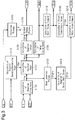
Fig. 3 is a block diagram representing the configuration by means of which the control device controls the vehicle drive force in the hybrid vehicle ofFig. 1 ; -
Fig. 4 is a timing diagram representing changes in the accelerator position, the required drive force, the target torque, and the vehicle acceleration at the time of vehicle acceleration in a comparative example; -
Fig. 5 is a timing diagram representing changes in the accelerator position, the required drive force, the target torque, and the vehicle acceleration in the control device for a hybrid vehicle ofFig. 1 at the time of vehicle acceleration; and -
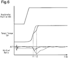
Fig. 6 is a timing diagram representing changes in the accelerator position, the required drive force, the target torque, and the vehicle acceleration at the time of vehicle acceleration in the hybrid vehicle inFig. 1 when the target torque is corrected in correspondence with the air-fuel ratio. - A control device for a hybrid vehicle according to an embodiment of the present disclosure will now be described with reference to
Figs. 1 to 6 . - As illustrated in
Fig. 1 , a hybrid vehicle employing the control device of the present embodiment has apower unit 10 to generate drive force for traveling. Thepower unit 10 has anengine 11 and two, first and second, motor-generators generators - The
power unit 10 has aplanetary gear mechanism 17 having three rotary elements, that is, asun gear 14, aplanetary carrier 15, and aring gear 16. Acrankshaft 18 of theengine 11 and a rotary shaft 19 of the first motor-generator 12 are joined to theplanetary carrier 15 and thesun gear 14 of theplanetary gear mechanism 17, respectively, each in an integrally rotatable manner. Acounter drive gear 20 is formed integrally with thering gear 16 of theplanetary gear mechanism 17. A counter drivengear 21 is meshed with thecounter drive gear 20. Areduction gear 22 is meshed with the counter drivengear 21. A rotary shaft 23 of the second motor-generator 13 is joined to thereduction gear 22 in an integrally rotatable manner. - The counter driven
gear 21 of thepower unit 10, which has the above-described configuration, is joined to afinal drive gear 24 in an integrally rotatable manner. In the present embodiment, the shaft that couples the counter drivengear 21 and thefinal drive gear 24 together serves as anoutput shaft 25 of thepower unit 10. A final drivengear 26 is meshed with thefinal drive gear 24.Drive shafts 29 of left andright wheels 28 are joined to the final drivengear 26 through adifferential mechanism 27. -
Fig. 2 shows the configuration of the control device for a hybrid vehicle of the present embodiment. Referring to the diagram, the control device includes four electronic control units (four ECUs), which are apower managing ECU 30, anengine ECU 31, amotor ECU 32, and abattery ECU 33. The power managing ECU 30 manages electric power and drive power in the vehicle as a whole. The engine ECU 31 controls theengine 11. The motor ECU 32 controls the torque of each of the first and second motor-generators battery 35. In the present embodiment, theengine ECU 31 corresponds to an engine controlling section, and themotor ECU 32 corresponds to a motor controlling section. - Also referring to
Fig. 2 , the first and second motor-generators battery 35 through aninverter 34. Theinverter 34 regulates the amount of electric power transmitted between the first motor-generator 12 and thebattery 35 and the amount of electric power transmitted between the second motor-generator 13 and thebattery 35. - Detection results of sensors that detect traveling conditions of the vehicle, such as a
vehicle speed sensor 36 and anaccelerator position sensor 37, are input to thepower managing ECU 30. Thevehicle speed sensor 36 detects the traveling speed of the hybrid vehicle (the vehicle speed V). Theaccelerator position sensor 37 detects the amount of accelerator pedal manipulation by the driver (the accelerator position ACC). Also, information representing operating conditions of theengine 11, such as the engine speed NE, the engine load KL, and a detection value of the air-fuel ratio (hereinafter, referred to as a detected air-fuel ratio AF), are input to thepower managing ECU 30. Further, themotor ECU 32 inputs information representing operating conditions of the motor-generators, such as the numbers of rotation of the first and second motor-generators 12, 13 (the first motor speed NM1 and the second motor speed NM2), to thepower managing ECU 30. Also, thebattery ECU 33 inputs information representing conditions of thebattery 35, such as the state of charge SOC and the battery temperature TB, to thepower managing ECU 30. - Based on the input information, the
power managing ECU 30 calculates a target engine speed NE* and a target torque TE*, that is, the target value of the engine speed NE and the target value of the engine torque TE, respectively, and then outputs the target engine speed NE* and the target torque TE* to theengine ECU 31. Thepower managing ECU 30 also calculates a first motor torque command TM1* and a second motor torque command TM2*, which are the command value of the torque generated by the first motor-generator 12 and the command value of the torque generated by the second motor-generator 13, respectively, and outputs the first motor and second motor torque commands TM1* and TM2* to themotor ECU 32. Then, theengine ECU 31 controls theengine 11 based on the target engine speed NE* and the target torque TE* and themotor ECU 32 controls theinverter 34 based on the first motor torque command TM1* and the second motor torque command TM2*. In these manners, the vehicle is driven and controlled. Specifically, theengine ECU 31 regulates the intake air amount of theengine 11 such that the amount of intake air flowing into each cylinder (the cylinder inflow air amount) reaches the amount necessary for producing the engine torque TE corresponding to the target torque TE*. Theengine ECU 31 then calculates the fuel injection amount that is necessary for causing the air-fuel ratio to reach the target value of the air-fuel ratio with respect to the regulated cylinder inflow air amount and thus performs fuel injection control on theengine 11. In this manner, theengine ECU 31 carries out engine control such that the engine torque TE becomes equal to the target torque TE*. -
Fig. 3 represents a procedure performed by thepower managing ECU 30 to drive and control the vehicle. According to the procedure, the target engine speed NE*, the target torque TE*, the first motor torque command TM1*, and the second motor torque command TM2* are calculated. Thepower managing ECU 30 performs the procedure ofFig. 3 repeatedly at predetermined calculation cycles during activation of the vehicle. - To drive and control the vehicle, a required drive force TP* is calculated, in Step S100, based on the vehicle speed V and the accelerator position ACC. The required drive force TP* is the request value of the drive force of the vehicle.
- Also, in Step S110, a required charging-discharging power PB* is calculated. The required charging-discharging power PB* is the request value of the drive force that is used in charging-discharging control on the
battery 35. The charging-discharging control is carried out to maintain the charging amount SOC at a predetermined control target. Specifically, when the charging amount SOC is greater than the control target, the power running of the second motor-generator 13 is performed to discharge thebattery 35. If the charging amount SOC is smaller than the control target, the regenerative operation of the second motor-generator 13 is performed to charge thebattery 35. In the charging-discharging control, the required charging-discharging power PB* is a positive value when the power running of the second motor-generator 13 should be carried out and is a negative value when the regenerative operation of the second motor-generator 13 should be performed. - Then, in Step S120, the difference between the required drive force TP* and the required charging-discharging power PB* is calculated as a required power PE*. The required power PE* is the request value of the drive force generated by the
engine 11. Based on the required power PE*, the required torque TEF*, that is, the request value of the engine torque TE, is calculated in Step S130. Also, the target engine speed NE* for theengine 11 is calculated in Step S140. The required torque TEF* and the target engine speed NE* represent such an engine torque TE and such an engine speed NE, respectively, that the engine output necessary for generating the drive force corresponding to the required power PE* can be produced in a state in which fuel efficiency and exhaust performance are optimal. - In Step S150, the required torque TEF* is subjected to a gradual change process through which change of the value is lessened. The obtained value is determined as the target torque TE*. In the present embodiment, the target torque TE* is calculated by being updated to satisfy the equation (1) in the gradual change process. In the equation (1), TE*[i-1] and TE*[i] represent the pre-update value of the target torque and the post-update value of the target torque, respectively. The value K represents a constant used to determine the degree of lessening change in the value. The greater the constant K, the smaller the change in the target torque TE* with respect to the change in the required torque TEF*. Through such calculation, the target torque TE* is determined as a value that changes after delay in response with respect to change in the accelerator position ACC.

- Specifically, in the present embodiment, the constant K in the equation (1) is set based on the detected air-fuel ratio AF in a correcting process of Step S160. The constant K is set to a greater value when the difference between the target value of the air-fuel ratio of the engine 11 (hereinafter, referred to as the target air-fuel ratio AFT) and the detected air-fuel ratio AF is greater than or equal to a predetermined value α than when the difference is smaller than the value α. Therefore, in the gradual change process of Step S150, the target torque TE* is calculated such that the change in the target torque TE* becomes more limited, that is, the delay in response with respect to the accelerator position ACC becomes greater, when the aforementioned difference is greater than or equal to the value α than when the difference is smaller than the value α. Although the target torque TE* is not directly manipulated in the aforementioned correcting process, the target torque TE* is changed, as a consequence, in correspondence with the difference between the target air-fuel ratio AFT and the detected air-fuel ratio AF. That is, the correcting process is substantially a process of correcting the target torque TE* in correspondence with the difference between the target air-fuel ratio AFT and the detected air-fuel ratio AF.
- In Step S170, the first motor torque command TM1* is calculated based on the target engine speed NE*. The first motor torque command TM1* is the torque of the first motor-
generator 12 that is necessary for causing the engine speed NE to reach the target engine speed NE*. In Step S180, a direct transmission torque TEQ* is calculated. The direct transmission torque TEQ* is the torque transmitted from theengine 11 to theoutput shaft 25 of thepower unit 10 in a state in which theengine 11 is operated in correspondence with the target engine speed NE* and the target torque TE* and the first motor-generator 12 is driven in correspondence with the first motortorque command TM 1*. - Meanwhile, in Step S190, the required drive force TP* is subjected to a shock lessening process and thus determined as a final required drive force TPSM*. In the shock lessening process, the final required drive force TPSM* is calculated by performing a guarding process on the upper and lower limits of the change rate of the required drive force TP* to such an extent that the torque shock caused by a sudden change in the drive force does not occur.
- In Step S200, a required PU output shaft torque TPC* is calculated based on the final required drive force TPSM*. The required PU output shaft torque TPC* is the torque of the
output shaft 25 of thepower unit 10 when the drive force corresponding to the final required drive force TPSM* is produced. Then, in Step S210, the difference between the required PU output shaft torque TPC* and the direct transmission torque TEQ* is calculated as the second motor torque command TM2*, which is the command value of the torque of the second motor-generator 13. Specifically, the second motor torque command TM2* represents the torque transmitted from the second motor-generator 13 to theoutput shaft 25 through thereduction gear 22 and the counter drivengear 21. - Specifically, to lessen the torque shock, highly responsive torque regulation is necessary. In this regard, in the present embodiment, the target torque TE* for the
engine 11 is calculated from the required drive force TP* and the second motor torque command TM2* is calculated from the final required drive force TPSM*, which is obtained by subjecting the required drive force TP* to the shock lessening process. That is, the torque regulation for lessening the torque shock is carried out by the second motor-generator 13. The second motor-generator 13 is capable of performing torque regulation with higher responsivity than theengine 11. - An operation and advantages of the present embodiment will now be described.
- A sudden change in the engine torque may destabilize the air-fuel ratio and thus degrade the emission of the
engine 11. In the present embodiment, the gradual change process determines the target torque TE* as a value with limited change such that, even at the time of a sudden change in the accelerator position ACC, a sudden change in the engine torque does not occur. This limits deterioration of emission. - In contrast, in a certain case of controlling the drive force of a vehicle, for example, the gradual change process for obtaining the target torque TE* may not be performed. In this case, the required torque TEF*, which is calculated from the required drive force TP*, is set directly to the target torque TE*. Even in the case, if the required drive force TP* is determined as a value with sufficiently limited change, that is, the gradual change process is carried out to obtain the required drive force TP*, instead of the target torque TE*, the deterioration of emission caused by a sudden change in the engine torque is limited.
-
Fig. 4 represents changes in the accelerator position ACC, the required drive force TP*, the target torque TE*, and the vehicle acceleration at the time the accelerator pedal is abruptly depressed in the above-described case. In this case, to limit the change in the target torque TE* to such an extent that deterioration of emission does not occur, the required drive force TP* must be set as a value with change limited to the same extent as the target torque TE*. However, this delays the change in the required drive force TP* with respect to the change in the accelerator position ACC, thus correspondingly increasing the delay amount of response of the vehicle drive force with respect to the driver's manipulation of the accelerator pedal. -
Fig. 5 represents changes in the accelerator position ACC, the required drive force TP*, the target torque TE*, and the vehicle acceleration in the control device of the present embodiment at the time of abrupt depression of the accelerator pedal. The graph represents a change in the vehicle acceleration in the case ofFig. 4 by a broken line for the purpose of comparison. - Also in the present embodiment, the gradual change process is performed to determine the target torque TE* for the
engine 11 as a value that changes in an lessened manner to such an extent that deterioration of emission does not occur. On the other hand, in the embodiment, the required drive force TP* is calculated as a value that changes without delay with respect to change in the accelerator position ACC. The first and second motor-generators engine 11 without decreasing the responsivity of the drive force. - Specifically, even when the above-described gradual change process is performed to calculate the target torque TE*, an excessively sudden change in the accelerator position ACC may hamper sufficient lessening of change in the target torque TE* and thus temporarily destabilize the air-fuel ratio of the
engine 11. To solve this problem, in the present embodiment, the correcting process is carried out to limit such destabilization of the air-fuel ratio. -
Fig. 6 represents changes in the accelerator position ACC, the target torque TE*, and the detected air-fuel ratio AF in the control device of the present embodiment in a case in which the drive force increases in response to abrupt depression of the accelerator pedal and the air-fuel ratio of theengine 11 becomes destabilized. Specifically, the graph also represents, by broken lines, changes in the target torque TE* and the detected air-fuel ratio AF in a case in which the target torque TE* is set without being subjected to the correcting process. - With reference to
Fig. 6 , at Time t1 when the target torque TE* is increasing in response to depression of the accelerator pedal, the difference between the target air-fuel ratio AFT and the detected air-fuel ratio AF becomes greater than or equal to the predetermined value α. At time t2, the aforementioned difference becomes smaller than the value α. In the present embodiment, in the period from Time t1 to Time t2, the constant K, which is used to calculate the target torque TE*, is set to a value greater than a normal value through the correcting process. Therefore, in the period from Time t1 to Time t2, the target torque TE* is determined as a value with limited change compared to a normal value. This lessens change in the engine torque TE, thus limiting destabilization of the air-fuel ratio. - Specifically, in the present embodiment, the
power managing ECU 30 executes a process as a required drive force calculating section through a required drive force calculating process (S100) and a process as a required torque calculating section through a required torque calculating process (S130). Also, thepower managing ECU 30 performs a process as a gradual change processing section through the gradual change process (S150) and a process as a correction processing section through the correcting process (S160). - The present embodiment may be modified as follows. Further, the present embodiment and the following modifications can be combined as long as the combined modifications remain technically consistent with each other.
- In the present embodiment, by updating the target torque TE* for the
engine 11 using the equation (1), the target torque TE* is determined as a value obtained by subjecting the required torque TEF* to the gradual change process to lessen change in the target torque TE*. Alternatively, as long as the target torque TE* is determined as a value with lessened change compared to the required torque TEF*, the target torque TE* may be calculated in any other manner than the aforementioned manner in the gradual change process. - In the present embodiment, the correcting process changes the constant K in two different manners depending on whether the difference in the air-fuel ratio is smaller than the predetermined value α or greater than or equal to the value α. Alternatively, the constant K may be changed, depending on the aforementioned difference, in three different manners or in a continuous manner.
- In the present embodiment, the correcting process is carried out by changing the constant K, which is used to calculate the target torque TE*, in correspondence with the difference between the target value and the detection value of the air-fuel ratio of the
engine 11. However, the correcting process may be performed in any other manner than the aforementioned manner. In other words, any other process can be employed as the correcting process, as long as the process corrects the target torque TE* in correspondence with the difference in the air-fuel ratio such that change in the target torque TE is lessened when the difference is great compared to when the difference is small. For example, a process in which the target torque TE* is manipulated directly in correspondence with the difference in the air-fuel ratio may be employed as the correcting process. - The target torque TE* may be calculated without being subjected to the correcting process in correspondence with the difference in the air-fuel ratio.
- In the present embodiment, the second motor torque command TM2* is calculated based on the final required drive force TPSM*, which is obtained by subjecting the required drive force TP* to the shock lessening process. Alternatively, the second motor torque command TM2* may be calculated based on the required drive force TP* without performing the shock lessening process.
- The control device of the present embodiment is employed in a hybrid vehicle that includes the
engine 11 and the first and second motor-generators - The control device that implements the above-described various control sections can be constructed by a device that an ECU executing software processing, but is not limited to this configuration. For example, at least part of the processes executed by the software in the above-described embodiments may be executed by hardware circuits dedicated to execution of these processes (such as ASIC). That is, the controller may be modified as long as it has any one of the following configurations (a) to (c). (a) A configuration including a processor that executes all of the above-described processes according to programs and a program storage device such as a ROM (including a non-transitory computer readable medium) that stores the programs. (b) A configuration including a processor and a program storage device that execute part of the above-described processes according to the programs and a dedicated hardware circuit that executes the remaining processes. (c) A configuration including a dedicated hardware circuit that executes all of the above-described processes. A plurality of software processing circuits each including a processor and a program storage device and a plurality of dedicated hardware circuits may be provided. That is, the above processes may be executed in any manner as long as the processes are executed by processing circuitry that includes at least one of a set of one or more software processing circuits and a set of one or more dedicated hardware circuits.
Claims (4)
- A control device for a hybrid vehicle, the hybrid vehicle including an engine (11) and a motor (12, 13) as drive sources for traveling, the control device characterized by comprising:a required drive force calculating section (30) that is configured to calculate a required drive force (TP*) based on an accelerator position (ACC);a required torque calculating section (30) that is configured to calculate a required torque (TEF*) of the engine (11) based on the required drive force (TP*);a gradual change processing section (30) that is configured to calculate a target torque (TE*) for the engine (11) by subjecting the required torque (TEF*) to a gradual change process for lessening a change in a value;an engine controlling section (31) that is configured to perform an engine control such that an engine torque becomes equal to the target torque (TE*); anda motor controlling section (32) that is configured to perform a torque control on the motor (12, 13) such that a drive force of the hybrid vehicle becomes equal to the required drive force (TP*) in a state in which the engine torque is equal to the target torque (TE*).
- The control device according to claim 1, characterized by further comprising a correction processing section (30) that is configured to correct the target torque (TE*) based on a difference between a target value (AFT) of an air-fuel ratio of the engine (11) and a detection value (AF) of the air-fuel ratio.
- A control method for a hybrid vehicle, the hybrid vehicle including an engine (11) and a motor (12, 13) as drive sources for traveling, the control method characterized by comprising:a required drive force calculating process for calculating a required drive force (TP*) based on an accelerator position (ACC);a required torque calculating process for calculating a required torque (TEF*) of the engine (11) based on the required drive force (TP*);a change lessening process for calculating a target torque (TE*) for the engine (11) by subjecting the required torque (TEF*) to the gradual change process for lessening a change in a value;an engine control process for performing an engine control such that an engine torque becomes equal to the target torque (TE*); anda motor control process for performing a torque control on the motor (12, 13) such that a drive force of the hybrid vehicle becomes equal to the required drive force (TP*) in a state in which the engine torque is equal to the target torque (TE*).
- A non-transitory computer-readable medium that stores a program that causes a processor to perform a control process for an hybrid vehicle, the hybrid vehicle including an engine (11) and a motor (12, 13) as drive sources for traveling, the control process characterized by comprising:a required drive force calculating process for calculating a required drive force (TP*) based on an accelerator position (ACC);a required torque calculating process for calculating a required torque (TEF*) of the engine (11) based on the required drive force (TP*);a gradual change process for calculating a target torque (TE*) for the engine (11) by subjecting the required torque (TEF*) to the gradual change process for lessening a change in a value;an engine control process for performing an engine control such that an engine torque becomes equal to the target torque (TE*); anda motor control process for performing a torque control on the motor (12, 13) such that a drive force of the hybrid vehicle becomes equal to the required drive force (TP*) in a state in which the engine torque is equal to the target torque (TE*).
Applications Claiming Priority (1)
| Application Number | Priority Date | Filing Date | Title |
|---|---|---|---|
| JP2018026203A JP7027937B2 (en) | 2018-02-16 | 2018-02-16 | Hybrid vehicle control device |
Publications (2)
| Publication Number | Publication Date |
|---|---|
| EP3527447A1 true EP3527447A1 (en) | 2019-08-21 |
| EP3527447B1 EP3527447B1 (en) | 2026-04-01 |
Family
ID=65440784
Family Applications (1)
| Application Number | Title | Priority Date | Filing Date |
|---|---|---|---|
| EP19157010.0A Active EP3527447B1 (en) | 2018-02-16 | 2019-02-13 | Control device and control method for hybrid vehicle |
Country Status (4)
| Country | Link |
|---|---|
| US (1) | US11130484B2 (en) |
| EP (1) | EP3527447B1 (en) |
| JP (1) | JP7027937B2 (en) |
| CN (1) | CN110155033B (en) |
Families Citing this family (1)
| Publication number | Priority date | Publication date | Assignee | Title |
|---|---|---|---|---|
| CN111645667B (en) * | 2020-04-23 | 2021-08-31 | 吉泰车辆技术(苏州)有限公司 | Torque control method, device and equipment for parallel mode of hybrid vehicle and vehicle |
Citations (5)
| Publication number | Priority date | Publication date | Assignee | Title |
|---|---|---|---|---|
| JP2006158154A (en) | 2004-12-01 | 2006-06-15 | Toyota Motor Corp | Vehicle control device |
| US20070266711A1 (en) * | 2004-09-15 | 2007-11-22 | Robert Bosch Gmbh | Method for Operating a Vehicle Drive and Device for Carrying Out Said Method |
| DE102008042544A1 (en) * | 2008-10-01 | 2010-04-08 | Robert Bosch Gmbh | Method for operating a vehicle with a hybrid engine system and engine system and vehicle |
| DE102012201111A1 (en) * | 2012-01-26 | 2013-08-01 | Zf Friedrichshafen Ag | Hybrid drive operating method for use in motor vehicle, involves providing turbocharger, performing boost pressure reduction, and providing set of compressors for turbocharger that is partially compensated |
| US20150203100A1 (en) * | 2014-01-23 | 2015-07-23 | GM Global Technology Operations LLC | Diesel engine aftertreatment heating and cleaning hybrid operation |
Family Cites Families (8)
| Publication number | Priority date | Publication date | Assignee | Title |
|---|---|---|---|---|
| JP3699592B2 (en) | 1998-06-19 | 2005-09-28 | 本田技研工業株式会社 | Control device for hybrid drive vehicle |
| US8897975B2 (en) * | 2007-11-04 | 2014-11-25 | GM Global Technology Operations LLC | Method for controlling a powertrain system based on penalty costs |
| JP2011063089A (en) | 2009-09-16 | 2011-03-31 | Mitsubishi Fuso Truck & Bus Corp | Device for control of hybrid electric vehicle |
| JPWO2012104904A1 (en) * | 2011-01-31 | 2014-07-03 | スズキ株式会社 | Hybrid vehicle drive control device, control method, and hybrid vehicle |
| CN104918834B (en) * | 2013-01-24 | 2017-07-07 | 丰田自动车株式会社 | The control device of motor vehicle driven by mixed power |
| JP5742984B1 (en) * | 2014-02-26 | 2015-07-01 | トヨタ自動車株式会社 | Control device for hybrid vehicle |
| JP6213497B2 (en) | 2015-02-25 | 2017-10-18 | トヨタ自動車株式会社 | Hybrid vehicle |
| JP6168085B2 (en) * | 2015-03-19 | 2017-07-26 | トヨタ自動車株式会社 | Hybrid vehicle |
-
2018
- 2018-02-16 JP JP2018026203A patent/JP7027937B2/en active Active
-
2019
- 2019-01-18 US US16/251,106 patent/US11130484B2/en not_active Expired - Fee Related
- 2019-01-23 CN CN201910061804.5A patent/CN110155033B/en active Active
- 2019-02-13 EP EP19157010.0A patent/EP3527447B1/en active Active
Patent Citations (5)
| Publication number | Priority date | Publication date | Assignee | Title |
|---|---|---|---|---|
| US20070266711A1 (en) * | 2004-09-15 | 2007-11-22 | Robert Bosch Gmbh | Method for Operating a Vehicle Drive and Device for Carrying Out Said Method |
| JP2006158154A (en) | 2004-12-01 | 2006-06-15 | Toyota Motor Corp | Vehicle control device |
| DE102008042544A1 (en) * | 2008-10-01 | 2010-04-08 | Robert Bosch Gmbh | Method for operating a vehicle with a hybrid engine system and engine system and vehicle |
| DE102012201111A1 (en) * | 2012-01-26 | 2013-08-01 | Zf Friedrichshafen Ag | Hybrid drive operating method for use in motor vehicle, involves providing turbocharger, performing boost pressure reduction, and providing set of compressors for turbocharger that is partially compensated |
| US20150203100A1 (en) * | 2014-01-23 | 2015-07-23 | GM Global Technology Operations LLC | Diesel engine aftertreatment heating and cleaning hybrid operation |
Also Published As
| Publication number | Publication date |
|---|---|
| EP3527447B1 (en) | 2026-04-01 |
| US11130484B2 (en) | 2021-09-28 |
| JP2019142282A (en) | 2019-08-29 |
| JP7027937B2 (en) | 2022-03-02 |
| US20190256081A1 (en) | 2019-08-22 |
| CN110155033A (en) | 2019-08-23 |
| CN110155033B (en) | 2022-07-29 |
Similar Documents
| Publication | Publication Date | Title |
|---|---|---|
| EP3216638B1 (en) | Hybrid vehicle and control method for hybrid vehicle | |
| EP1526020B1 (en) | Power output apparatus and automobile with power output apparatus mounted thereon | |
| US9771058B2 (en) | Control method of hybrid vehicle | |
| CN111114523B (en) | Device and method for generating driving torque command for operating a hybrid electric vehicle | |
| KR20190138118A (en) | Control apparatus and method for generating drive torque command of eco-friendly vehicle | |
| KR102529518B1 (en) | Control apparatus and method for generating drive torque command of eco-friendly vehicle | |
| CN110386128B (en) | Electric vehicle | |
| US20140024491A1 (en) | Hybrid vehicle | |
| CN100509462C (en) | Vehicle and vehicle control method | |
| JP2016088381A (en) | Hybrid car | |
| US20140180441A1 (en) | Control device of vehicle and control method therefor | |
| US11130495B2 (en) | Control apparatus for hybrid vehicle | |
| JP4311400B2 (en) | Hybrid vehicle and control method thereof | |
| EP3527447B1 (en) | Control device and control method for hybrid vehicle | |
| JP4281750B2 (en) | Vehicle and vehicle control method | |
| JP2024078322A (en) | Hybrid vehicle charging control device | |
| JP5682639B2 (en) | Hybrid car | |
| JPH1118210A (en) | Control device for hybrid system vehicle | |
| JP7211254B2 (en) | vehicle controller | |
| JP2005124282A (en) | Automobile and control method thereof | |
| JP2008143316A (en) | Power output device, control method and vehicle | |
| JP4039409B2 (en) | Power output apparatus, automobile equipped with the same, and control method of power output apparatus | |
| JP2013147198A (en) | Hybrid vehicle | |
| US20240190414A1 (en) | Control apparatus for vehicle | |
| JP2007210409A (en) | Vehicle and vehicle control method |
Legal Events
| Date | Code | Title | Description |
|---|---|---|---|
| PUAI | Public reference made under article 153(3) epc to a published international application that has entered the european phase |
Free format text: ORIGINAL CODE: 0009012 |
|
| STAA | Information on the status of an ep patent application or granted ep patent |
Free format text: STATUS: REQUEST FOR EXAMINATION WAS MADE |
|
| 17P | Request for examination filed |
Effective date: 20190312 |
|
| AK | Designated contracting states |
Kind code of ref document: A1 Designated state(s): AL AT BE BG CH CY CZ DE DK EE ES FI FR GB GR HR HU IE IS IT LI LT LU LV MC MK MT NL NO PL PT RO RS SE SI SK SM TR |
|
| AX | Request for extension of the european patent |
Extension state: BA ME |
|
| STAA | Information on the status of an ep patent application or granted ep patent |
Free format text: STATUS: EXAMINATION IS IN PROGRESS |
|
| 17Q | First examination report despatched |
Effective date: 20220913 |
|
| GRAP | Despatch of communication of intention to grant a patent |
Free format text: ORIGINAL CODE: EPIDOSNIGR1 |
|
| STAA | Information on the status of an ep patent application or granted ep patent |
Free format text: STATUS: GRANT OF PATENT IS INTENDED |
|
| INTG | Intention to grant announced |
Effective date: 20251114 |
|
| GRAS | Grant fee paid |
Free format text: ORIGINAL CODE: EPIDOSNIGR3 |
|
| GRAA | (expected) grant |
Free format text: ORIGINAL CODE: 0009210 |
|
| STAA | Information on the status of an ep patent application or granted ep patent |
Free format text: STATUS: THE PATENT HAS BEEN GRANTED |
|
| AK | Designated contracting states |
Kind code of ref document: B1 Designated state(s): AL AT BE BG CH CY CZ DE DK EE ES FI FR GB GR HR HU IE IS IT LI LT LU LV MC MK MT NL NO PL PT RO RS SE SI SK SM TR |
|
| REG | Reference to a national code |
Ref country code: CH Ref legal event code: F10 Free format text: ST27 STATUS EVENT CODE: U-0-0-F10-F00 (AS PROVIDED BY THE NATIONAL OFFICE) Effective date: 20260401 Ref country code: GB Ref legal event code: FG4D |
|
| REG | Reference to a national code |
Ref country code: DE Ref legal event code: R096 Ref document number: 602019083037 Country of ref document: DE |
|
| REG | Reference to a national code |
Ref country code: IE Ref legal event code: FG4D |