EP3527409A1 - Commercial vehicle structure for refrigerated road vehicles - Google Patents
Commercial vehicle structure for refrigerated road vehicles Download PDFInfo
- Publication number
- EP3527409A1 EP3527409A1 EP19155130.8A EP19155130A EP3527409A1 EP 3527409 A1 EP3527409 A1 EP 3527409A1 EP 19155130 A EP19155130 A EP 19155130A EP 3527409 A1 EP3527409 A1 EP 3527409A1
- Authority
- EP
- European Patent Office
- Prior art keywords
- cover layer
- commercial vehicle
- inner cover
- air guide
- vehicle body
- Prior art date
- Legal status (The legal status is an assumption and is not a legal conclusion. Google has not performed a legal analysis and makes no representation as to the accuracy of the status listed.)
- Granted
Links
- 238000001816 cooling Methods 0.000 claims abstract description 13
- 230000002787 reinforcement Effects 0.000 claims description 4
- 229910052782 aluminium Inorganic materials 0.000 claims description 3
- XAGFODPZIPBFFR-UHFFFAOYSA-N aluminium Chemical compound [Al] XAGFODPZIPBFFR-UHFFFAOYSA-N 0.000 claims description 3
- 239000011810 insulating material Substances 0.000 claims description 3
- 239000002023 wood Substances 0.000 claims description 2
- 239000000463 material Substances 0.000 claims 2
- 238000010276 construction Methods 0.000 claims 1
- 239000006260 foam Substances 0.000 claims 1
- 229910001220 stainless steel Inorganic materials 0.000 claims 1
- 239000010935 stainless steel Substances 0.000 claims 1
- 238000003756 stirring Methods 0.000 claims 1
- 238000003466 welding Methods 0.000 claims 1
- 238000004140 cleaning Methods 0.000 abstract description 3
- 238000004519 manufacturing process Methods 0.000 abstract description 2
- 125000006850 spacer group Chemical group 0.000 description 2
- 244000052616 bacterial pathogen Species 0.000 description 1
- 239000012459 cleaning agent Substances 0.000 description 1
- 150000001875 compounds Chemical class 0.000 description 1
- 239000003599 detergent Substances 0.000 description 1
- 238000003912 environmental pollution Methods 0.000 description 1
- 229910052751 metal Inorganic materials 0.000 description 1
- 239000002184 metal Substances 0.000 description 1
- 230000006911 nucleation Effects 0.000 description 1
- 238000010899 nucleation Methods 0.000 description 1
- 238000005057 refrigeration Methods 0.000 description 1
- 239000000126 substance Substances 0.000 description 1
Images


Classifications
-
- B—PERFORMING OPERATIONS; TRANSPORTING
- B60—VEHICLES IN GENERAL
- B60H—ARRANGEMENTS OF HEATING, COOLING, VENTILATING OR OTHER AIR-TREATING DEVICES SPECIALLY ADAPTED FOR PASSENGER OR GOODS SPACES OF VEHICLES
- B60H1/00—Heating, cooling or ventilating [HVAC] devices
- B60H1/00007—Combined heating, ventilating, or cooling devices
- B60H1/00014—Combined heating, ventilating, or cooling devices for load cargos on load transporting vehicles
-
- B—PERFORMING OPERATIONS; TRANSPORTING
- B60—VEHICLES IN GENERAL
- B60H—ARRANGEMENTS OF HEATING, COOLING, VENTILATING OR OTHER AIR-TREATING DEVICES SPECIALLY ADAPTED FOR PASSENGER OR GOODS SPACES OF VEHICLES
- B60H1/00—Heating, cooling or ventilating [HVAC] devices
- B60H1/00507—Details, e.g. mounting arrangements, desaeration devices
- B60H1/00557—Details of ducts or cables
- B60H1/00564—Details of ducts or cables of air ducts
-
- B—PERFORMING OPERATIONS; TRANSPORTING
- B62—LAND VEHICLES FOR TRAVELLING OTHERWISE THAN ON RAILS
- B62D—MOTOR VEHICLES; TRAILERS
- B62D33/00—Superstructures for load-carrying vehicles
- B62D33/04—Enclosed load compartments ; Frameworks for movable panels, tarpaulins or side curtains
- B62D33/048—Enclosed load compartments ; Frameworks for movable panels, tarpaulins or side curtains for refrigerated goods vehicles
-
- B—PERFORMING OPERATIONS; TRANSPORTING
- B65—CONVEYING; PACKING; STORING; HANDLING THIN OR FILAMENTARY MATERIAL
- B65D—CONTAINERS FOR STORAGE OR TRANSPORT OF ARTICLES OR MATERIALS, e.g. BAGS, BARRELS, BOTTLES, BOXES, CANS, CARTONS, CRATES, DRUMS, JARS, TANKS, HOPPERS, FORWARDING CONTAINERS; ACCESSORIES, CLOSURES, OR FITTINGS THEREFOR; PACKAGING ELEMENTS; PACKAGES
- B65D88/00—Large containers
- B65D88/74—Large containers having means for heating, cooling, aerating or other conditioning of contents
- B65D88/744—Large containers having means for heating, cooling, aerating or other conditioning of contents heating or cooling through the walls or internal parts of the container, e.g. circulation of fluid inside the walls
-
- F—MECHANICAL ENGINEERING; LIGHTING; HEATING; WEAPONS; BLASTING
- F25—REFRIGERATION OR COOLING; COMBINED HEATING AND REFRIGERATION SYSTEMS; HEAT PUMP SYSTEMS; MANUFACTURE OR STORAGE OF ICE; LIQUEFACTION SOLIDIFICATION OF GASES
- F25D—REFRIGERATORS; COLD ROOMS; ICE-BOXES; COOLING OR FREEZING APPARATUS NOT OTHERWISE PROVIDED FOR
- F25D17/00—Arrangements for circulating cooling fluids; Arrangements for circulating gas, e.g. air, within refrigerated spaces
- F25D17/005—Arrangements for circulating cooling fluids; Arrangements for circulating gas, e.g. air, within refrigerated spaces in cold rooms
-
- B—PERFORMING OPERATIONS; TRANSPORTING
- B60—VEHICLES IN GENERAL
- B60P—VEHICLES ADAPTED FOR LOAD TRANSPORTATION OR TO TRANSPORT, TO CARRY, OR TO COMPRISE SPECIAL LOADS OR OBJECTS
- B60P3/00—Vehicles adapted to transport, to carry or to comprise special loads or objects
- B60P3/20—Refrigerated goods vehicles
Definitions
- the invention relates to a commercial vehicle body for refrigerated vehicles with one of a load compartment floor, side walls, a roof, a rear wall or rear wall doors and an end wall limited cargo space, the end wall of air guide profiles has limited air ducts, which is assigned to a provided on the end wall cooling device for the load compartment are.
- the commercial vehicle structure of the type mentioned is characterized in that the end wall is provided with an inner cover layer facing the cargo space formed in the inner cover layer air guide profiles and the air ducts, the air guide profiles and the inner cover layer are integrally formed.
- the end wall has an inner cover layer, which formed as profiled component both the air flow and the air guide profiles as integrated into the inner cover layer Having areas that can be manufactured with a unique manufacturing process, without the need for subsequent fixings.
- the air guide profiles can also be trapezoidal or otherwise formed with z. B. flattened, the cargo space facing ends. Between these air guide profiles extend the air ducts that are assigned to the cooling unit.
- the air guide profiles can simultaneously form a collision protection and a system as a pallet stop or charge stop. These have an open to the cargo area side inner space or cavity in which reinforcements are to be used, such as aluminum or wooden slats or wooden slats.
- the end wall may be designed so that it has the one-piece or one-piece inner cover layer and an outer cover layer arranged at a distance therebetween, between which there is a panel closing the inner cover layer towards the rear, ie to the outer cover layer, for example a wooden panel, the spacing therebetween Wood panel and the outer cover layer by a heat-insulating material can be foamed.
- the air ducts and also the air guide profiles can extend up to an air baffle, behind which the cooling device is arranged. Cooled air can flow from the cooling unit back into the cargo compartment via an air outlet. Heated air from the hold is fed via air ducts of the front wall and passes from below behind the air baffle.
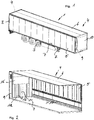
- a commercial vehicle is numbered that is formed in the embodiments shown as supported on a chassis 2 and wheels 3 semi-trailer, with a commercial vehicle body 4 with side walls 5, a roof 6, a cargo compartment floor 7, a rear wall 8, which also z. B. two personallyschwenkende rear doors, and an end wall 9, to which a cooling device 10 is attached.
- Fig. 2 shows a view into the loading space 11 and a view of the inside of the end wall 9, with the inner cover layer 12, which is associated with the loading space 11.
- This inner cover layer is formed as a profiled aluminum sheet metal part with air guide profiles 13 facing the cargo space and air ducts 14 located between these air guide profiles 13, which extend as far as an air guide plate 15, which is provided at a distance from the inner cover layer 12 and forms an air feed for the cooling device 10.
- the inner cover layer 12 and the Air guide sections 13 and air ducts 14 are integrally formed, so that no fastening means such as screws, rivets and the like for the attachment of the air guide profiles 13. Like. Are required.
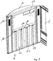
- Fig. 3 shows once again enlarged the end wall 9 and indicated sidewalls 5 and the inner cover layer 12, the air ducts 14 and the air guide profiles 13.
- the air guide profiles 13 also form spacers and pallet or charge stops, so that in their inner space partially with a gain in shape are reinforced by wooden slats 16.
- An air opening 17 is provided from the cooling unit 10 to the loading space 11, so that cooled air, indicated by the arrows 18, can be fed back to the loading space 11. Heated air is supplied via the air ducts 14, indicated by the arrows 19, via the air guide plate 15 to the cooling device 10.
- FIG. 4, 5 . 6 and 7 clarify once again the structure of the front wall 4 with the there adapted cooling device 10 of the inner cover layer 12 with the air guide profiles 13 and the air ducts 14, but also that at a distance from the inner cover layer 12 and an outer cover layer 20 is provided, behind the inner cover layer 12 is a extend over the width and height partially extending plate, such as a wooden plate, which is back-foamed to the outer cover layer 20 with a heat-insulating material.
- the wooden strips 16 are indicated as reinforcements.
Abstract
Die Erfindung bezieht sich auf einen Nutzfahrzeugaufbau für Kühlfahrzeuge mit einem von einem Laderaumboden, Seitenwänden 5, einem Dach sowie von einer Stirnwand 9 und von einer Heckwand umgrenzten Laderaum, wobei an der Stirnwand 9 ein Kühlgerät 10 vorgesehen und an der Stirnwand 9 dem Kühlgerät 10 zugeordnete Luftführungskanäle 14 ausgebildet sind, die von Luftleitprofilen 13 begrenzt sind. Um diesen Nutzfahrzeugaufbau hinsichtlich des Fertigungsaufwandes und bei einem späteren Einsatz hinsichtlich des Reinigungsaufwandes zu verbessern, ist vorgesehen, dass die Stirnwand 9 mit einer dem Laderaum 11 zugewandten Innendeckschicht 12 mit in der Innendeckschicht 12 ausgeformten Luftführungsprofilen 13 versehen ist und die Luftführungskanäle 14, die Luftführungsprofile 13 und die Innendeckschicht 12 einstückig ausgebildet sindThe invention relates to a commercial vehicle body for refrigerated vehicles with one of a load compartment floor, side walls 5, a roof and an end wall 9 and a rear wall bounded cargo space, wherein provided on the end wall 9, a cooling device 10 and associated with the cooling unit 10 on the end wall 9 Air ducts 14 are formed, which are bounded by Luftleitprofilen 13. In order to improve this commercial vehicle structure in terms of manufacturing costs and later use in terms of cleaning effort, it is provided that the end wall 9 is provided with an inner cover layer 12 facing the cargo space 11 with air guide profiles 13 formed in the inner cover layer 12 and the air guide channels 14, the air guide profiles 13 and the inner cover layer 12 are integrally formed
Description
Die Erfindung bezieht sich auf einen Nutzfahrzeugaufbau für Kühlfahrzeuge mit einem von einem Laderaumboden, Seitenwänden, einem Dach, einer Heckwand oder Heckwandtüren sowie einer Stirnwand begrenzten Laderaum, wobei die Stirnwand von Luftführungsprofilen begrenzte Luftführungen aufweist, die einem an der Stirnwand vorgesehenen Kühlgerät für den Laderaum zugeordnet sind.The invention relates to a commercial vehicle body for refrigerated vehicles with one of a load compartment floor, side walls, a roof, a rear wall or rear wall doors and an end wall limited cargo space, the end wall of air guide profiles has limited air ducts, which is assigned to a provided on the end wall cooling device for the load compartment are.
Nutzfahrzeugaufbauten der vorgenannten Art sind bekannt und haben Luftführungsprofile, die aus mehreren Einzelteilen bestehen, die auf der dem Laderaum zugewandten Seite der Stirnwand des Nutzfahrzeugaufbaus aufgebracht sind. Erwärmte Luft wird dabei in den Luftführungskanälen zwischen den aufgesetzten Luftführungsprofilen zwischen der Stirnwand und dem auf den Laderaumboden abgestellten Ladegut zum Kühlaggregat zurücktransportiert. Zusätzlich sollen diese Luftleitprofile auch noch die Funktion eines Anfahrschutzes und einer Anlage für die Ladung darbieten und damit auch einen Palettenanschlag bzw. einen Abstandshalter darstellen.Commercial vehicle bodies of the aforementioned type are known and have air guide profiles, which consist of several individual parts, which are applied to the side facing the loading space side of the front wall of the commercial vehicle body. Heated air is transported back to the refrigeration unit in the air ducts between the mounted air guide profiles between the front wall and parked on the load floor cargo. In addition, these Luftleitprofile also offer the function of a collision and a system for the cargo and thus represent a pallet stop or a spacer.
Nachteilig ist hierbei, dass die Luftleitprofile durch herkömmliche Verbindungen wie Schrauben und Niete mit der Stirnwand verbunden sind, welche sowohl die Luftleitprofile als auch die Stirnwand schwächen. Darüber hinaus ist es außerordentlich schwierig und auch zeitaufwändig, die Stirnwand inklusive aller mit dieser verbundenen Bauteile zu reinigen und zu desinfizieren. Darauf ist aber insbesondere bei Kühlfahrzeugen großer Wert zu legen ist, da im Laderaum von Kühlfahrzeugen vielfach verderbliche Waren wie Lebensmittel transportiert werden. Daher ist die Hygiene in einem Laderaum eines Kühlfahrzeuges mit hohem Aufwand sicherzustellen. Darüber hinaus müssen auch Spalte und ggf. auch Risse zwischen Stirnwand und Sockelleisten entweder aufwändig gereinigt oder durch Versiegelungen geschlossen werden. Solche Versiegelungen altern jedoch und weisen ihrerseits mit der Zeit Risse und Spalte auf, was wiederum eine erhöhte Gefahr von Keimbildungen mit sich bringt. Der Reinigungsaufwand mit chemischen Reinigungsmitteln ist daher erheblich, wodurch Umweltbelastungen einhergehen.The disadvantage here is that the Luftleitprofile are connected by conventional compounds such as screws and rivets with the end wall, which weaken both the Luftleitprofile and the front wall. In addition, it is extremely difficult and time-consuming to clean and disinfect the front wall including all associated with this components. But that's it great importance is to be placed in particular in refrigerated vehicles, since in the hold of refrigerated vehicles perishable goods such as food are transported. Therefore, the hygiene in a hold of a refrigerated vehicle with great effort to ensure. In addition, gaps and possibly also cracks between the end wall and baseboards must either be laboriously cleaned or closed by seals. However, such seals age and in turn have cracks and crevices over time, which in turn increases the risk of nucleation. The cleaning effort with chemical cleaning agents is therefore significant, which is associated with environmental pollution.
Es ist Aufgabe der vorliegenden Erfindung, einen Nutzfahrzeugaufbau der eingangs genannten Art derart weiterzubilden, dass der Laderaum mit vermindertem Aufwand zu reinigen ist und der Hygienestandard innerhalb des Fahrzeugaufbaus und damit innerhalb des Laderaumes mit vermindertem Aufwand sicherzustellen ist.It is an object of the present invention, a commercial vehicle structure of the type mentioned in such a way that the load compartment is to be cleaned with reduced effort and the standard of hygiene within the vehicle body and thus within the hold with reduced effort is ensured.
Zur Lösung dieser Aufgabe zeichnet sich der Nutzfahrzeugaufbau der eingangs genannten Art dadurch aus, dass die Stirnwand mit einer dem Laderaum zugewandten Innendeckschicht mit in der Innendeckschicht ausgeformten Luftführungsprofilen versehen ist und die Luftführungskanäle, die Luftführungsprofile und die Innendeckschicht einstückig ausgebildet sind.To solve this problem, the commercial vehicle structure of the type mentioned is characterized in that the end wall is provided with an inner cover layer facing the cargo space formed in the inner cover layer air guide profiles and the air ducts, the air guide profiles and the inner cover layer are integrally formed.
Damit ist ein Nutzfahrzeugaufbau zur Verfügung gestellt, bei dem die Stirnwand eine Innendeckschicht aufweist, die als profiliert ausgebildetes Bauteil sowohl die Luftführung als auch die Luftführungsprofile als in die Innendeckschicht integrierte Bereiche aufweist, die mit einem einmaligen Herstellungsprozess gefertigt werden kann, ohne dass es nachträglicher Befestigungen bedarf. Von der Querschnittsgeometrie können die Luftführungsprofile auch trapezförmig oder andersförmig ausgebildet sein mit z. B. abgeflachten, dem Laderaum zugewandten Enden. Zwischen diesen Luftführungsprofilen erstrecken sich die Luftführungen, die dem Kühlgerät zugeordnet sind. Die Luftführungsprofile können gleichzeitig einen Anfahrschutz und eine Anlage als Palettenanschlag bzw. Ladungsanschlag ausbilden. Diese haben einen zu der dem Laderaum abgeneigten Seite offenen inneren Raum bzw. Hohlraum, in den auch Verstärkungen einzusetzen sind, beispielsweise Aluminium oder Holzlatten oder Holzleisten.Thus, a commercial vehicle structure is provided, in which the end wall has an inner cover layer, which formed as profiled component both the air flow and the air guide profiles as integrated into the inner cover layer Having areas that can be manufactured with a unique manufacturing process, without the need for subsequent fixings. From the cross-sectional geometry, the air guide profiles can also be trapezoidal or otherwise formed with z. B. flattened, the cargo space facing ends. Between these air guide profiles extend the air ducts that are assigned to the cooling unit. The air guide profiles can simultaneously form a collision protection and a system as a pallet stop or charge stop. These have an open to the cargo area side inner space or cavity in which reinforcements are to be used, such as aluminum or wooden slats or wooden slats.
Insgesamt bieten sich jedoch an dieser dem Laderaum zugewandten Stirnwand keinerlei Spalte oder Räume im Bereich von Muttern von z. B. Befestigungsschrauben, an denen sich Schmutz oder Keime absetzen könnten, die nur schwer zu reinigen sind. Insgesamt ist der Reinigungsaufwand dieser Stirnwand wesentlich geringer und schneller zu vollziehen, so dass auch der Hygienestandard in dem Laderaum des Nutzfahrzeuges wesentlich einfacher sicherzustellen ist und die Umwelt belastenden Reinigungsmittel eingespart werden.Altogether, however, no gaps or spaces in the range of nuts of z. As fastening screws on which dirt or germs could settle, which are difficult to clean. Overall, the cleaning effort of this end wall is much lower and faster to perform, so that the standard of hygiene in the hold of the commercial vehicle is much easier to ensure and the environment polluting detergent can be saved.
Die Stirnwand kann so gestaltet sein, dass sie die einteilige bzw. einstückige Innendeckschicht und eine mit Abstand zu dieser angeordnete Außendeckschicht aufweist, zwischen denen eine die Innendeckschicht nach hinten hin, d. h. zur Außendeckschicht abschließende Platte aufweist, beispielsweise eine Holzplatte, wobei der Abstand zwischen dieser Holzplatte und der Außendeckschicht durch ein wärmedämmendes Material ausgeschäumt werden kann. Die Luftführungen und auch die Luftführungsprofile können sich bis zu einer Luftleitplatte erstrecken, hinter der das Kühlgerät angeordnet ist. Über einen Luftauslass kann gekühlte Luft wieder vom Kühlgerät in den Laderaum strömen. Erwärmte Luft aus dem Laderaum wird über Luftführungen der Stirnwand zugeführt und gelangt von diesen von unten hinter die Luftleitplatte.The end wall may be designed so that it has the one-piece or one-piece inner cover layer and an outer cover layer arranged at a distance therebetween, between which there is a panel closing the inner cover layer towards the rear, ie to the outer cover layer, for example a wooden panel, the spacing therebetween Wood panel and the outer cover layer by a heat-insulating material can be foamed. The air ducts and also the air guide profiles can extend up to an air baffle, behind which the cooling device is arranged. Cooled air can flow from the cooling unit back into the cargo compartment via an air outlet. Heated air from the hold is fed via air ducts of the front wall and passes from below behind the air baffle.
Wesentliche weitere Ausgestaltungen sind weiteren Unteransprüchen, der nachfolgenden Beschreibung und der Zeichnung zu entnehmen. In der Zeichnung zeigen:
- Fig. 1:
- Ein perspektivisches Ausführungsbeispiel eines Nutzfahrzeuges mit einem Ausführungsbeispiel eines Nutzfahrzeugaufbaus;
- Fig. 2:
- das Ausführungsbeispiel des Nutzfahrzeugaufbaus nach
Fig. 1 mit Blick in den Laderaum bei nicht dargestellter Heckwand und einer nicht dargestellten Seitenwand; - Fig. 3:
- vom Laderaum betrachtet einen Blick auf ein Ausführungsbeispiel einer Stirnwand ohne Luftleitplatte;
- Fig. 4:
- die Darstellung nach
Fig. 3 versehen mit Schnittlinien A-A, B-B und C-C; - Fig. 5:
- perspektivisch eine Ansicht auf die Schnittlinie gemäß A-A;
- Fig. 6:
- die perspektivische Darstellung gemäß der Schnittlinie B-B in einer perspektivischen Darstellung, und
- Fig. 7:
- die Schnittlinie C-C in einer perspektivischen Darstellung.
- Fig. 1:
- A perspective embodiment of a commercial vehicle with an embodiment of a commercial vehicle body;
- Fig. 2:
- the embodiment of the commercial vehicle body after
Fig. 1 with a view into the hold at not shown rear wall and a side wall, not shown; - 3:
- from the loading space considered a view of an embodiment of an end wall without Luftleitplatte;
- 4:
- the representation after
Fig. 3 provided with section lines AA, BB and CC; - Fig. 5:
- in perspective, a view of the section line according to AA;
- Fig. 6:
- the perspective view along the section line BB in a perspective view, and
- Fig. 7:
- the section line CC in a perspective view.
In der Zeichnung sind übereinstimmende Teile mit übereinstimmenden Bezugsziffern versehen.In the drawing, matching parts are provided with corresponding reference numerals.
Allgemein mit 1 ist ein Nutzfahrzeug beziffert, dass in den gezeigten Ausführungsbeispielen als auf einem Fahrgestell 2 und Rädern 3 abgestützter Sattelauflieger ausgebildet ist, mit einem Nutzfahrzeugaufbau 4 mit Seitenwänden 5, einem Dach 6, einem Laderaumboden 7, einer Heckwand 8, die auch z. B. zwei aufzuschwenkende Hecktüren aufweisen kann, sowie einer Stirnwand 9, an der ein Kühlgerät 10 befestigt ist.Generally with 1 a commercial vehicle is numbered that is formed in the embodiments shown as supported on a chassis 2 and
Die Ansichten nach den
Claims (13)
Applications Claiming Priority (1)
| Application Number | Priority Date | Filing Date | Title |
|---|---|---|---|
| DE102018001180.2A DE102018001180A1 (en) | 2018-02-15 | 2018-02-15 | Commercial vehicle body for refrigerated vehicles |
Publications (2)
| Publication Number | Publication Date |
|---|---|
| EP3527409A1 true EP3527409A1 (en) | 2019-08-21 |
| EP3527409B1 EP3527409B1 (en) | 2022-08-10 |
Family
ID=65278268
Family Applications (1)
| Application Number | Title | Priority Date | Filing Date |
|---|---|---|---|
| EP19155130.8A Active EP3527409B1 (en) | 2018-02-15 | 2019-02-01 | Commercial vehicle structure for refrigerated road vehicles |
Country Status (5)
| Country | Link |
|---|---|
| EP (1) | EP3527409B1 (en) |
| DE (1) | DE102018001180A1 (en) |
| DK (1) | DK3527409T3 (en) |
| ES (1) | ES2929914T3 (en) |
| PL (1) | PL3527409T3 (en) |
Cited By (1)
| Publication number | Priority date | Publication date | Assignee | Title |
|---|---|---|---|---|
| CN112572265A (en) * | 2019-09-29 | 2021-03-30 | 张国义 | Multifunctional transport vehicle |
Citations (5)
| Publication number | Priority date | Publication date | Assignee | Title |
|---|---|---|---|---|
| US4399737A (en) * | 1981-06-10 | 1983-08-23 | J. Charles Peterson | Corrugated air return bulkhead |
| US4593536A (en) * | 1985-06-21 | 1986-06-10 | Burlington Northern Railroad Company | Carbon dioxide refrigeration system |
| US5807046A (en) * | 1996-02-26 | 1998-09-15 | Onken; Greg | Air return bulkhead |
| US6132307A (en) * | 1998-11-30 | 2000-10-17 | Image Rotomolding Enterprises, Inc. | Removable intake screen for refrigeration unit air flow panel |
| WO2015179138A1 (en) * | 2014-05-21 | 2015-11-26 | Carrier Corporation | Adjustable height return air bulkhead |
-
2018
- 2018-02-15 DE DE102018001180.2A patent/DE102018001180A1/en not_active Withdrawn
-
2019
- 2019-02-01 EP EP19155130.8A patent/EP3527409B1/en active Active
- 2019-02-01 ES ES19155130T patent/ES2929914T3/en active Active
- 2019-02-01 DK DK19155130.8T patent/DK3527409T3/en active
- 2019-02-01 PL PL19155130.8T patent/PL3527409T3/en unknown
Patent Citations (5)
| Publication number | Priority date | Publication date | Assignee | Title |
|---|---|---|---|---|
| US4399737A (en) * | 1981-06-10 | 1983-08-23 | J. Charles Peterson | Corrugated air return bulkhead |
| US4593536A (en) * | 1985-06-21 | 1986-06-10 | Burlington Northern Railroad Company | Carbon dioxide refrigeration system |
| US5807046A (en) * | 1996-02-26 | 1998-09-15 | Onken; Greg | Air return bulkhead |
| US6132307A (en) * | 1998-11-30 | 2000-10-17 | Image Rotomolding Enterprises, Inc. | Removable intake screen for refrigeration unit air flow panel |
| WO2015179138A1 (en) * | 2014-05-21 | 2015-11-26 | Carrier Corporation | Adjustable height return air bulkhead |
Cited By (1)
| Publication number | Priority date | Publication date | Assignee | Title |
|---|---|---|---|---|
| CN112572265A (en) * | 2019-09-29 | 2021-03-30 | 张国义 | Multifunctional transport vehicle |
Also Published As
| Publication number | Publication date |
|---|---|
| DE102018001180A1 (en) | 2019-08-22 |
| EP3527409B1 (en) | 2022-08-10 |
| ES2929914T3 (en) | 2022-12-02 |
| PL3527409T3 (en) | 2023-01-23 |
| DK3527409T3 (en) | 2022-11-14 |
Similar Documents
| Publication | Publication Date | Title |
|---|---|---|
| DE102008036338A1 (en) | Vehicle body with a bottom reinforcement | |
| DE102013001945A1 (en) | Schweller for car body, has schweller reinforcement element comprising access port that provides entrance to connection region for producing connection between inner hollow section portion and body support element | |
| EP3527409B1 (en) | Commercial vehicle structure for refrigerated road vehicles | |
| EP1319584B2 (en) | Dump body for a vehicle | |
| DE19622675C2 (en) | Sidewall assembly with an outer, half-shell profiled sidewall part | |
| DE976897C (en) | Car body for cars and similar vehicles | |
| EP2703214B1 (en) | Partition wall for a commercial vehicle and commercial vehicle with such a partition wall | |
| DE4318838A1 (en) | Wall panel for vehicle bodies | |
| EP3431372A1 (en) | Board wall element and commercial vehicle with such a board wall element | |
| EP0235330B1 (en) | Trailer for a passenger vehicle | |
| DE4439077A1 (en) | Stowage box for fitting under a truck body | |
| DE102021108665A1 (en) | Composite profile for a box body for a utility vehicle and box body for a utility vehicle | |
| DE19617454C2 (en) | Protective grille or partition for the interior of motor vehicles | |
| EP3527468A1 (en) | Box body for commercial vehicles | |
| DE102015013708A1 (en) | Cross member for a bumper of a motor vehicle, bumper and cars | |
| DE102006023169B4 (en) | Component for a commercial vehicle body, commercial vehicle with such a component and method for producing such a component | |
| DE2611141A1 (en) | Side folding door for lorry - has telescopic fastening system with parallel rods in upper and lower guides bridged by flexible connection | |
| DE102014111540A1 (en) | System for constructing shelves in vehicles | |
| EP1110812A2 (en) | Space dividers for closed superstructures for trucks | |
| EP3590800A1 (en) | Box body for a commercial vehicle provided with load securing profile | |
| DE102021128294B3 (en) | Holding device, insulating panel with a holding device, vehicle body, in particular refrigerated vehicle body, use of such a holding device | |
| EP3695996B1 (en) | Box body with short-circuit barrier | |
| EP3437926A1 (en) | Luggage structure for a commercial vehicle | |
| DE10114077B4 (en) | Insulation of the refrigerated space of refrigerated trucks | |
| EP0325250A1 (en) | Double floor board for a ventilated container |
Legal Events
| Date | Code | Title | Description |
|---|---|---|---|
| PUAI | Public reference made under article 153(3) epc to a published international application that has entered the european phase |
Free format text: ORIGINAL CODE: 0009012 |
|
| STAA | Information on the status of an ep patent application or granted ep patent |
Free format text: STATUS: THE APPLICATION HAS BEEN PUBLISHED |
|
| AK | Designated contracting states |
Kind code of ref document: A1 Designated state(s): AL AT BE BG CH CY CZ DE DK EE ES FI FR GB GR HR HU IE IS IT LI LT LU LV MC MK MT NL NO PL PT RO RS SE SI SK SM TR |
|
| AX | Request for extension of the european patent |
Extension state: BA ME |
|
| STAA | Information on the status of an ep patent application or granted ep patent |
Free format text: STATUS: REQUEST FOR EXAMINATION WAS MADE |
|
| 17P | Request for examination filed |
Effective date: 20191016 |
|
| RBV | Designated contracting states (corrected) |
Designated state(s): AL AT BE BG CH CY CZ DE DK EE ES FI FR GB GR HR HU IE IS IT LI LT LU LV MC MK MT NL NO PL PT RO RS SE SI SK SM TR |
|
| STAA | Information on the status of an ep patent application or granted ep patent |
Free format text: STATUS: EXAMINATION IS IN PROGRESS |
|
| 17Q | First examination report despatched |
Effective date: 20200728 |
|
| STAA | Information on the status of an ep patent application or granted ep patent |
Free format text: STATUS: EXAMINATION IS IN PROGRESS |
|
| GRAP | Despatch of communication of intention to grant a patent |
Free format text: ORIGINAL CODE: EPIDOSNIGR1 |
|
| STAA | Information on the status of an ep patent application or granted ep patent |
Free format text: STATUS: GRANT OF PATENT IS INTENDED |
|
| RIC1 | Information provided on ipc code assigned before grant |
Ipc: B65D 88/74 20060101ALI20220211BHEP Ipc: B60P 3/20 20060101ALI20220211BHEP Ipc: B62D 33/04 20060101ALI20220211BHEP Ipc: B65D 90/02 20190101ALI20220211BHEP Ipc: F25D 17/00 20060101ALI20220211BHEP Ipc: B60H 1/00 20060101AFI20220211BHEP |
|
| GRAS | Grant fee paid |
Free format text: ORIGINAL CODE: EPIDOSNIGR3 |
|
| INTG | Intention to grant announced |
Effective date: 20220307 |
|
| GRAA | (expected) grant |
Free format text: ORIGINAL CODE: 0009210 |
|
| STAA | Information on the status of an ep patent application or granted ep patent |
Free format text: STATUS: THE PATENT HAS BEEN GRANTED |
|
| AK | Designated contracting states |
Kind code of ref document: B1 Designated state(s): AL AT BE BG CH CY CZ DE DK EE ES FI FR GB GR HR HU IE IS IT LI LT LU LV MC MK MT NL NO PL PT RO RS SE SI SK SM TR |
|
| REG | Reference to a national code |
Ref country code: AT Ref legal event code: REF Ref document number: 1510257 Country of ref document: AT Kind code of ref document: T Effective date: 20220815 Ref country code: CH Ref legal event code: EP |
|
| REG | Reference to a national code |
Ref country code: DE Ref legal event code: R096 Ref document number: 502019005201 Country of ref document: DE |
|
| REG | Reference to a national code |
Ref country code: IE Ref legal event code: FG4D Free format text: LANGUAGE OF EP DOCUMENT: GERMAN |
|
| REG | Reference to a national code |
Ref country code: DK Ref legal event code: T3 Effective date: 20221108 |
|
| REG | Reference to a national code |
Ref country code: NL Ref legal event code: FP |
|
| REG | Reference to a national code |
Ref country code: SE Ref legal event code: TRGR |
|
| REG | Reference to a national code |
Ref country code: ES Ref legal event code: FG2A Ref document number: 2929914 Country of ref document: ES Kind code of ref document: T3 Effective date: 20221202 |
|
| REG | Reference to a national code |
Ref country code: LT Ref legal event code: MG9D |
|
| PG25 | Lapsed in a contracting state [announced via postgrant information from national office to epo] |
Ref country code: RS Free format text: LAPSE BECAUSE OF FAILURE TO SUBMIT A TRANSLATION OF THE DESCRIPTION OR TO PAY THE FEE WITHIN THE PRESCRIBED TIME-LIMIT Effective date: 20220810 Ref country code: PT Free format text: LAPSE BECAUSE OF FAILURE TO SUBMIT A TRANSLATION OF THE DESCRIPTION OR TO PAY THE FEE WITHIN THE PRESCRIBED TIME-LIMIT Effective date: 20221212 Ref country code: NO Free format text: LAPSE BECAUSE OF FAILURE TO SUBMIT A TRANSLATION OF THE DESCRIPTION OR TO PAY THE FEE WITHIN THE PRESCRIBED TIME-LIMIT Effective date: 20221110 Ref country code: LV Free format text: LAPSE BECAUSE OF FAILURE TO SUBMIT A TRANSLATION OF THE DESCRIPTION OR TO PAY THE FEE WITHIN THE PRESCRIBED TIME-LIMIT Effective date: 20220810 Ref country code: LT Free format text: LAPSE BECAUSE OF FAILURE TO SUBMIT A TRANSLATION OF THE DESCRIPTION OR TO PAY THE FEE WITHIN THE PRESCRIBED TIME-LIMIT Effective date: 20220810 Ref country code: FI Free format text: LAPSE BECAUSE OF FAILURE TO SUBMIT A TRANSLATION OF THE DESCRIPTION OR TO PAY THE FEE WITHIN THE PRESCRIBED TIME-LIMIT Effective date: 20220810 |
|
| PG25 | Lapsed in a contracting state [announced via postgrant information from national office to epo] |
Ref country code: IS Free format text: LAPSE BECAUSE OF FAILURE TO SUBMIT A TRANSLATION OF THE DESCRIPTION OR TO PAY THE FEE WITHIN THE PRESCRIBED TIME-LIMIT Effective date: 20221210 Ref country code: HR Free format text: LAPSE BECAUSE OF FAILURE TO SUBMIT A TRANSLATION OF THE DESCRIPTION OR TO PAY THE FEE WITHIN THE PRESCRIBED TIME-LIMIT Effective date: 20220810 Ref country code: GR Free format text: LAPSE BECAUSE OF FAILURE TO SUBMIT A TRANSLATION OF THE DESCRIPTION OR TO PAY THE FEE WITHIN THE PRESCRIBED TIME-LIMIT Effective date: 20221111 |
|
| PGFP | Annual fee paid to national office [announced via postgrant information from national office to epo] |
Ref country code: NL Payment date: 20230220 Year of fee payment: 5 |
|
| PG25 | Lapsed in a contracting state [announced via postgrant information from national office to epo] |
Ref country code: SM Free format text: LAPSE BECAUSE OF FAILURE TO SUBMIT A TRANSLATION OF THE DESCRIPTION OR TO PAY THE FEE WITHIN THE PRESCRIBED TIME-LIMIT Effective date: 20220810 Ref country code: RO Free format text: LAPSE BECAUSE OF FAILURE TO SUBMIT A TRANSLATION OF THE DESCRIPTION OR TO PAY THE FEE WITHIN THE PRESCRIBED TIME-LIMIT Effective date: 20220810 Ref country code: CZ Free format text: LAPSE BECAUSE OF FAILURE TO SUBMIT A TRANSLATION OF THE DESCRIPTION OR TO PAY THE FEE WITHIN THE PRESCRIBED TIME-LIMIT Effective date: 20220810 |
|
| PGFP | Annual fee paid to national office [announced via postgrant information from national office to epo] |
Ref country code: FR Payment date: 20230217 Year of fee payment: 5 Ref country code: ES Payment date: 20230317 Year of fee payment: 5 Ref country code: DK Payment date: 20230220 Year of fee payment: 5 |
|
| REG | Reference to a national code |
Ref country code: DE Ref legal event code: R097 Ref document number: 502019005201 Country of ref document: DE |
|
| PG25 | Lapsed in a contracting state [announced via postgrant information from national office to epo] |
Ref country code: SK Free format text: LAPSE BECAUSE OF FAILURE TO SUBMIT A TRANSLATION OF THE DESCRIPTION OR TO PAY THE FEE WITHIN THE PRESCRIBED TIME-LIMIT Effective date: 20220810 Ref country code: EE Free format text: LAPSE BECAUSE OF FAILURE TO SUBMIT A TRANSLATION OF THE DESCRIPTION OR TO PAY THE FEE WITHIN THE PRESCRIBED TIME-LIMIT Effective date: 20220810 |
|
| PGFP | Annual fee paid to national office [announced via postgrant information from national office to epo] |
Ref country code: TR Payment date: 20230131 Year of fee payment: 5 Ref country code: SE Payment date: 20230220 Year of fee payment: 5 Ref country code: PL Payment date: 20230119 Year of fee payment: 5 Ref country code: IT Payment date: 20230228 Year of fee payment: 5 Ref country code: BE Payment date: 20230220 Year of fee payment: 5 |
|
| PLBE | No opposition filed within time limit |
Free format text: ORIGINAL CODE: 0009261 |
|
| STAA | Information on the status of an ep patent application or granted ep patent |
Free format text: STATUS: NO OPPOSITION FILED WITHIN TIME LIMIT |
|
| P01 | Opt-out of the competence of the unified patent court (upc) registered |
Effective date: 20230518 |
|
| PG25 | Lapsed in a contracting state [announced via postgrant information from national office to epo] |
Ref country code: AL Free format text: LAPSE BECAUSE OF FAILURE TO SUBMIT A TRANSLATION OF THE DESCRIPTION OR TO PAY THE FEE WITHIN THE PRESCRIBED TIME-LIMIT Effective date: 20220810 |
|
| 26N | No opposition filed |
Effective date: 20230511 |
|
| PG25 | Lapsed in a contracting state [announced via postgrant information from national office to epo] |
Ref country code: SI Free format text: LAPSE BECAUSE OF FAILURE TO SUBMIT A TRANSLATION OF THE DESCRIPTION OR TO PAY THE FEE WITHIN THE PRESCRIBED TIME-LIMIT Effective date: 20220810 |
|
| PG25 | Lapsed in a contracting state [announced via postgrant information from national office to epo] |
Ref country code: MC Free format text: LAPSE BECAUSE OF FAILURE TO SUBMIT A TRANSLATION OF THE DESCRIPTION OR TO PAY THE FEE WITHIN THE PRESCRIBED TIME-LIMIT Effective date: 20220810 |
|
| REG | Reference to a national code |
Ref country code: CH Ref legal event code: PL |
|
| PG25 | Lapsed in a contracting state [announced via postgrant information from national office to epo] |
Ref country code: LU Free format text: LAPSE BECAUSE OF NON-PAYMENT OF DUE FEES Effective date: 20230201 Ref country code: LI Free format text: LAPSE BECAUSE OF NON-PAYMENT OF DUE FEES Effective date: 20230228 Ref country code: CH Free format text: LAPSE BECAUSE OF NON-PAYMENT OF DUE FEES Effective date: 20230228 |
|
| REG | Reference to a national code |
Ref country code: IE Ref legal event code: MM4A |
|
| PG25 | Lapsed in a contracting state [announced via postgrant information from national office to epo] |
Ref country code: IE Free format text: LAPSE BECAUSE OF NON-PAYMENT OF DUE FEES Effective date: 20230201 |
|
| PGFP | Annual fee paid to national office [announced via postgrant information from national office to epo] |
Ref country code: NL Payment date: 20240220 Year of fee payment: 6 Ref country code: ES Payment date: 20240319 Year of fee payment: 6 |
|
| PGFP | Annual fee paid to national office [announced via postgrant information from national office to epo] |
Ref country code: AT Payment date: 20240216 Year of fee payment: 6 Ref country code: AT Payment date: 20240216 Year of fee payment: 5 |
|
| PGFP | Annual fee paid to national office [announced via postgrant information from national office to epo] |
Ref country code: DE Payment date: 20240216 Year of fee payment: 6 Ref country code: GB Payment date: 20240222 Year of fee payment: 6 |