EP3527353A2 - Monolithic remote control - Google Patents
Monolithic remote control Download PDFInfo
- Publication number
- EP3527353A2 EP3527353A2 EP19164688.4A EP19164688A EP3527353A2 EP 3527353 A2 EP3527353 A2 EP 3527353A2 EP 19164688 A EP19164688 A EP 19164688A EP 3527353 A2 EP3527353 A2 EP 3527353A2
- Authority
- EP
- European Patent Office
- Prior art keywords
- housing
- mold
- plastic housing
- miter
- plastic
- Prior art date
- Legal status (The legal status is an assumption and is not a legal conclusion. Google has not performed a legal analysis and makes no representation as to the accuracy of the status listed.)
- Pending
Links
Images


Classifications
-
- H—ELECTRICITY
- H01—ELECTRIC ELEMENTS
- H01H—ELECTRIC SWITCHES; RELAYS; SELECTORS; EMERGENCY PROTECTIVE DEVICES
- H01H9/00—Details of switching devices, not covered by groups H01H1/00 - H01H7/00
- H01H9/02—Bases, casings, or covers
- H01H9/0214—Hand-held casings
- H01H9/0235—Hand-held casings specially adapted for remote control, e.g. of audio or video apparatus
- H01H9/0242—Protective enclosures; Cushioning means
-
- H—ELECTRICITY
- H01—ELECTRIC ELEMENTS
- H01H—ELECTRIC SWITCHES; RELAYS; SELECTORS; EMERGENCY PROTECTIVE DEVICES
- H01H9/00—Details of switching devices, not covered by groups H01H1/00 - H01H7/00
- H01H9/02—Bases, casings, or covers
- H01H9/0214—Hand-held casings
- H01H9/0235—Hand-held casings specially adapted for remote control, e.g. of audio or video apparatus
-
- B—PERFORMING OPERATIONS; TRANSPORTING
- B29—WORKING OF PLASTICS; WORKING OF SUBSTANCES IN A PLASTIC STATE IN GENERAL
- B29C—SHAPING OR JOINING OF PLASTICS; SHAPING OF MATERIAL IN A PLASTIC STATE, NOT OTHERWISE PROVIDED FOR; AFTER-TREATMENT OF THE SHAPED PRODUCTS, e.g. REPAIRING
- B29C45/00—Injection moulding, i.e. forcing the required volume of moulding material through a nozzle into a closed mould; Apparatus therefor
- B29C45/17—Component parts, details or accessories; Auxiliary operations
- B29C45/40—Removing or ejecting moulded articles
- B29C45/4005—Ejector constructions; Ejector operating mechanisms
- B29C45/401—Ejector pin constructions or mountings
-
- B—PERFORMING OPERATIONS; TRANSPORTING
- B29—WORKING OF PLASTICS; WORKING OF SUBSTANCES IN A PLASTIC STATE IN GENERAL
- B29C—SHAPING OR JOINING OF PLASTICS; SHAPING OF MATERIAL IN A PLASTIC STATE, NOT OTHERWISE PROVIDED FOR; AFTER-TREATMENT OF THE SHAPED PRODUCTS, e.g. REPAIRING
- B29C45/00—Injection moulding, i.e. forcing the required volume of moulding material through a nozzle into a closed mould; Apparatus therefor
- B29C45/17—Component parts, details or accessories; Auxiliary operations
- B29C45/40—Removing or ejecting moulded articles
-
- B—PERFORMING OPERATIONS; TRANSPORTING
- B29—WORKING OF PLASTICS; WORKING OF SUBSTANCES IN A PLASTIC STATE IN GENERAL
- B29C—SHAPING OR JOINING OF PLASTICS; SHAPING OF MATERIAL IN A PLASTIC STATE, NOT OTHERWISE PROVIDED FOR; AFTER-TREATMENT OF THE SHAPED PRODUCTS, e.g. REPAIRING
- B29C66/00—General aspects of processes or apparatus for joining preformed parts
- B29C66/01—General aspects dealing with the joint area or with the area to be joined
- B29C66/05—Particular design of joint configurations
- B29C66/10—Particular design of joint configurations particular design of the joint cross-sections
- B29C66/11—Joint cross-sections comprising a single joint-segment, i.e. one of the parts to be joined comprising a single joint-segment in the joint cross-section
- B29C66/116—Single bevelled joints, i.e. one of the parts to be joined being bevelled in the joint area
- B29C66/1162—Single bevel to bevel joints, e.g. mitre joints
-
- B—PERFORMING OPERATIONS; TRANSPORTING
- B29—WORKING OF PLASTICS; WORKING OF SUBSTANCES IN A PLASTIC STATE IN GENERAL
- B29C—SHAPING OR JOINING OF PLASTICS; SHAPING OF MATERIAL IN A PLASTIC STATE, NOT OTHERWISE PROVIDED FOR; AFTER-TREATMENT OF THE SHAPED PRODUCTS, e.g. REPAIRING
- B29C66/00—General aspects of processes or apparatus for joining preformed parts
- B29C66/50—General aspects of joining tubular articles; General aspects of joining long products, i.e. bars or profiled elements; General aspects of joining single elements to tubular articles, hollow articles or bars; General aspects of joining several hollow-preforms to form hollow or tubular articles
- B29C66/51—Joining tubular articles, profiled elements or bars; Joining single elements to tubular articles, hollow articles or bars; Joining several hollow-preforms to form hollow or tubular articles
- B29C66/54—Joining several hollow-preforms, e.g. half-shells, to form hollow articles, e.g. for making balls, containers; Joining several hollow-preforms, e.g. half-cylinders, to form tubular articles
-
- B—PERFORMING OPERATIONS; TRANSPORTING
- B29—WORKING OF PLASTICS; WORKING OF SUBSTANCES IN A PLASTIC STATE IN GENERAL
- B29C—SHAPING OR JOINING OF PLASTICS; SHAPING OF MATERIAL IN A PLASTIC STATE, NOT OTHERWISE PROVIDED FOR; AFTER-TREATMENT OF THE SHAPED PRODUCTS, e.g. REPAIRING
- B29C66/00—General aspects of processes or apparatus for joining preformed parts
- B29C66/70—General aspects of processes or apparatus for joining preformed parts characterised by the composition, physical properties or the structure of the material of the parts to be joined; Joining with non-plastics material
- B29C66/71—General aspects of processes or apparatus for joining preformed parts characterised by the composition, physical properties or the structure of the material of the parts to be joined; Joining with non-plastics material characterised by the composition of the plastics material of the parts to be joined
-
- B—PERFORMING OPERATIONS; TRANSPORTING
- B29—WORKING OF PLASTICS; WORKING OF SUBSTANCES IN A PLASTIC STATE IN GENERAL
- B29L—INDEXING SCHEME ASSOCIATED WITH SUBCLASS B29C, RELATING TO PARTICULAR ARTICLES
- B29L2031/00—Other particular articles
- B29L2031/34—Electrical apparatus, e.g. sparking plugs or parts thereof
- B29L2031/3481—Housings or casings incorporating or embedding electric or electronic elements
-
- H—ELECTRICITY
- H01—ELECTRIC ELEMENTS
- H01H—ELECTRIC SWITCHES; RELAYS; SELECTORS; EMERGENCY PROTECTIVE DEVICES
- H01H2231/00—Applications
- H01H2231/032—Remote control
-
- H—ELECTRICITY
- H05—ELECTRIC TECHNIQUES NOT OTHERWISE PROVIDED FOR
- H05K—PRINTED CIRCUITS; CASINGS OR CONSTRUCTIONAL DETAILS OF ELECTRIC APPARATUS; MANUFACTURE OF ASSEMBLAGES OF ELECTRICAL COMPONENTS
- H05K5/00—Casings, cabinets or drawers for electric apparatus
- H05K5/0004—Casings, cabinets or drawers for electric apparatus comprising several parts forming a closed casing
Definitions
- the present invention relates to a plastic housing for electronic devices, in particular remote controls.
- Such a plastic housing is for example from the DE 10 2010 045 944 A1 known. It comprises a first housing part and a second housing part, wherein the first housing part comprises a directed in the direction of the second housing part joining surface and the second housing part comprises a directed in the direction of the first housing part joining surface and wherein the two housing parts are assembled to the joining surfaces adjacent to each other.
- a plastic housing for electronic devices comprises a first housing part and a second housing part, wherein the first housing part comprises a directed in the direction of the second housing part joining surface and the second housing part comprises a directed in the direction of the first housing part joining surface wherein the two housing parts are assembled to the joining surfaces adjacent to each other, and wherein the joining surfaces are designed as miter surfaces.
- the specified plastic housing is based on the consideration that the aforementioned plastic housing has form-locking elements that the Enlarge joining surface and thus offer the two housing parts a wider attack surface against each other.
- the problem with the interlocking elements is that they must be matched exactly to one another, because otherwise a gap remains between the two housing parts in the assembled state of the plastic housing, which can be perceived as disturbing, especially in areas with high aesthetic requirements.
- the miter surfaces of the housing parts are at least partially formed circumferentially around an interior, which is adapted einhausen an electronic component of the electronic device.
- the miter surfaces are V-shaped and allow it to additionally center the two housing parts against each other.
- the miter surfaces simultaneously fulfill the function of the above-mentioned positive-locking elements.
- the miter surfaces are formed leading into the interior.
- all the blunt edges on the housing parts which are formed by the miter surfaces in the interior of the plastic housing.
- the blunt edges tools such as ejector pins, vent elements or the like can apply in a particularly favorable manner on the interior side in the manufacture of the housing parts, so that any remaining burrs or the like are no longer visible in retrospect.
- the specified plastic housing is produced by a method in which a primary molding material is introduced into the molding spaces forming the housing parts and air from the mold spaces at the ventilation points is discharged, which is located at or adjacent to places in the mold cavities, where the miter surfaces of the housing parts are formed.
- the primary molding material displaces the air present there when it is introduced into the mold space, so that the air must be removed from the mold space.
- the air is removed from the mold space at a parting plane between the tool parts which form the mold space.
- the miter surfaces and thus the molded parts on the outwardly directed side of the remote control are as precisely pointed as possible, the parting planes should be as dense as possible at this point, so that no primary molding material enters the parting plane and thus leaves a burr acting as a disturbing. Due to this dense design of the parting planes, venting of the mold space at the parting plane is practically impossible.
- venting point on or next to the miter surface, preferably in the interior of the plastic housing to be formed, so that the venting on the one hand takes place as close as possible to the miter surface to be formed and so can not be considered annoying burns, inclusions or the like, on the other but also production-related burrs or the like can be arranged in the interior of the plastic housing to be formed.
- leading channels are used for discharging the air from the mold spaces in the mold spaces in which ejector pins are inserted.
- the air duct is kept very small, through which the air is discharged from the mold space, so that after a complete venting of the mold space and correspondingly less primary material penetrates into the vent channel.
- the venting channel is automatically cleaned by the ejector pin when ejecting the urgeformten housing part.
- the primary molding material is introduced at injection points in the mold spaces, which is arranged on one side of the mold space, which is opposite to a side with the venting point.
- the injection points are arranged centrally in the mold spaces, as seen in a molding direction of the primary molding material. In this way it is ensured that the primary material can be distributed evenly in all directions of the mold space. In addition, however, it is also ensured that the primary molding material penetrates into the pointed areas of the mold cavity last and thus does not cure prematurely there, which could clog the mold cavity.
- the mold spaces are formed with mold plates which are hermetically sealed at a separating plane prior to the introduction of the primary mold material into the mold cavities. In this way, the above-mentioned burr at the parting plane in the mold space is avoided.
- the miter surfaces of the housing parts to be formed open into the parting plane.
- the ventilation points are located opposite the miter surfaces of the parting plane. In this way it is ensured that burrs or the like resulting from the venting are arranged in the interior of the plastic housing to be formed and are not visible from the outside.
- a primary molding material is introduced into a mold space forming the housing part, and air is introduced discharged from the mold space at a venting point, which is located at or adjacent to a point in the mold space at which the miter surface of the housing part is formed.
- a channel leading into the forming space is used for discharging the air from the mold space, into which an ejector pin is introduced.
- the primary molding material is introduced at an injection point in the mold space, which is arranged on one side of the mold space, which is opposite to a side with the venting point.
- the injection point is arranged on a central axis of the mold space.
- the mold space is formed by two tool molds which are hermetically sealed at a parting plane prior to introduction of the primary mold material into the mold space.
- the miter surface of the housing part to be formed open into the parting plane.
- the ventilation point is located opposite the miter surface of the parting plane.
- a housing part of one of the specified plastic housing is produced by one of the stated methods.
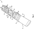
- FIG. 1 shows a remote control 1 for controlling an electronic device, not shown, such as a multimedia device in a perspective view.
- the remote control 1 comprises a plastic housing 2, which is composed of a first housing part in the form of an upper shell 3 and a second housing part lower shell 4, and two keypads 5 with a plurality of key elements 6.
- a plastic housing 2 which is composed of a first housing part in the form of an upper shell 3 and a second housing part lower shell 4, and two keypads 5 with a plurality of key elements 6.
- key elements 6 in the keypad 5 are in the figures of For clarity, not all provided with a reference numeral.
- a control pad 8 is arranged, which comprises a first key element 9, a second key element 10, a third key element 11 and a fourth key element 12.
- the four key elements 9 to 12 are arranged circumferentially and at intervals of 90 ° about a confirmation key 13.
- the control pad 8 with the four key elements 9 to 12 is formed here as a circular disc.
- 1 feedback elements 14 are arranged in the form of small lights on the remote control, which can light up depending on a keystroke on the remote control 1.
- the operation of the exemplary multimedia device is to be controlled.
- a user by means of the buttons 5 on the upper shell 3 of the remote control 1 control commands as information in the remote control 1, which are then transmitted by means of a not shown transmitter to the electronic device to be controlled.
- Such a command can be entered, for example, as a direction command on the key elements 9 to 12, then the movement of a control on the exemplary multimedia device in one of the four possible directions of movement controls.
- the illustration of the remote control 1 is merely exemplary in order to better understand the following technical explanations. However, they can be implemented on any electronic device and in particular on any remote control.
- the plastic housing 2 is produced by prototyping, which will be explained in the following technical embodiments based on the injection molding.
- Fig. 2a to 2c are sections of sectional views of a shell mold duration 15 shown, which provide a mold space 16 for injection molding of the upper shell 3 of the plastic housing 2.
- Fig. 3a to 3c Cutouts of sectional views of a Unterschalendauerform 17 shown that provide a mold cavity 16 for injection molding of the lower shell 4 of the plastic housing 2.
- the upper shell mold 15 comprises a pressure side 18, which is also called the nozzle side 18. Opposite the pressure side 18, the outer shell mold 15 comprises a closing side 19, which is also called the ejector side 19. On the pressure side 18 and closing side 19, the upper shell duration form 15 is enclosed by two clamping plates 20, on which the remaining elements of the upper shell duration form 15 are carried.
- Pressure side 18 is on the platen 20 is an in Fig. 4 shown mold plate 41 is worn, in which a mold insert 21 is inserted.
- a pressure matrix 22 is formed, which forms the convex outer surface of the plastic housing 2 on the upper shell 3.
- Closing side 19 an ejector housing 23 is supported on the platen 20, on the side opposite the platen 20 side with a Pressure plate 24 is closed.
- On the pressure plate 24 is an in Fig. 5 shown closing-side mold plate 41 is worn, in which a closing-side mold insert 21 is inserted.
- the matrix 22 and the core 25 together form the upper shell molding space 16.
- the guide channels 26 have shoulders 28 on which the ejector pins 27 could strike with corresponding counter shoulders 29. From the shoulders 28 and counter shoulders 29 are in the Fig. 2a and 2b not all provided with a reference numeral for clarity. These shoulders 28, 29 are due to the design, because an upper part of the ejector 27 is designed as a flat ejector, while the lower part of the ejector 27 is made for stability and manufacturing reasons around to increase the buckling load capacity.
- the flat ejectors of the ejector pins 27 are guided in the guide channels 26, while the circular areas of the ejector pins 27 are guided below the shoulders 29 in not further referenced Freibohrache.
- the ejector pins 27 are carried on an ejector base plate 30 and positioned in position by an ejector retaining plate 31.
- the two plates 30, 31 are arranged movably in the interior of the ejector housing 23 so that the ejector pins 27 can be moved over them.
- tempering holes 32 through which a temperature control, such as water can be performed to temper the upper shell mold space 16 by cooling or heating.
- a temperature control such as water
- the tempering holes 32 have a minimum distance from the mold space 16 on, which is 10 to 20 times smaller than a width of the upper shell 3 of the plastic housing 2. For the minimum distance 2mm were chosen in the present embodiment.
- the diameter of the Temperierbohronne 32 is between 4 and 5 times as large as the minimum distance. That would be in the present embodiment between 8mm and 10mm. The larger the tempering holes 32 are, the faster the tempering takes place.
- the Unterschalendauerform 17 is constructed in the same manner as the Oberschalendauerform 15. Therefore, in the Fig. 3a to 3c the same reference numerals used as in the Fig. 2a to 2c , The explanations given above with regard to the upper shell duration form 15 apply analogously to the Unterschalendauerform 17. Therefore, a renewed execution for the sake of brevity is omitted.
- a variothermic injection molding process is used for producing an upper shell 3 and / or a lower shell 4. While usually in the injection molding, in particular of plastic under the temperature cooling is understood to dissipate the heat energy of the molten master molding material, the mold cavity 16 is first heated in a variothermal injection molding process prior to injection of the master molding material and then cooled again.
- the mold insert 21 on the Pressure side 18 and on the closing side 19 equal tempered, that is, first warmed up. In this way, in particular during the injection molding of high-gloss housing parts 3, 4, it is ensured that no weld lines occur on the finished product.
- the corresponding mold space 16 is closed.
- the platen 20 is moved on the closing side 19 against the platen 20 on the pressure side 18 until the two mold plates 21, in which the matrix 20 and the core 25 is formed according to touch.
- the heated primary molding material is poured over a in Fig. 5 and 6 to be seen sprue 34 is pressed into the mold space 16.
- a high-gloss plastic housing 2 can be used as the original molding material for the shells 3, 4 methyl methacrylate-acrylonitrile-butadiene-styrene, which is known under the abbreviation M-ABS known.
- This primary molding material should be heated to 114 ° C prior to insertion into the mold cavity 16.
- the primary mold material introduced into the mold space 16 is distributed there and displaces the air present there. This must be removed accordingly, which will be discussed in more detail later.
- the mold inserts 21 are cooled again via the tempering bores 32, so that the primary molding material solidifies.
- cold water is driven through the tempering holes 32.
- the mold space 16 is opened and the molded part produced in this way is ejected from the tool via the ejector pins 27.
- the ejector base plate 30 presses the ejector pins 27 against the open Mold space 16, so that the molded there manufactured molding, so the upper shell 3 or the lower shell 4 dissolves and can fall out of the tool.
- the ejector pins 27 are withdrawn from the Auswerferhalteplatte 31 again, and the entire tool back to the initial state, so that the injection molding process can be restarted.
- the plastic housing 2 of the remote control 1 should be as monolithic as possible. If the upper shell 3 and the lower shell 4 are therefore assembled on a joint surface 36, then a butt joint between the two shells 3, 4 fall on an edge, so that between the two shells 3, 4 as possible no gap is visible. In this way, it would be difficult for the viewer to see whether the plastic housing 2 of the remote control 1 is a one-part or a multi-part component.
- the remote control 1 is replaced in this way a much slimmer appearance, especially when the upper shell 3 is performed in a color contrast to the lower shell 4.
- the joining surfaces 36 on the two shells 3, 4 are designed such that the two shells 3, 4 can be connected to one another via a miter connection. Therefore, the joining surfaces 36 will be referred to below as miter surfaces 36.
- miter surfaces 36 In the production of the miter surfaces 36, however, it should be noted that in this way jumps in the wall thickness 37 occur on the trays 3, 4 to be manufactured, which can lead to errors in the surfaces of the trays 3, 4 to be manufactured.
- the shells 3, 4 at the miter surfaces 36 must taper as far as possible. This requires that the wall thickness 37 drops from a normal wall thickness of, for example, 2 mm to a wall thickness of less than 0.2 mm. Therefore, when using the injection molding method explained above, care must be taken that due to the large cracks in the wall thickness 37, the formation of surface defects such as burns on the shells 3, 4 is not favored.
- a separating plane 38 between the mold inserts can be used for the abovementioned venting of the mold space 16.
- a gap would have to remain in the parting plane, through which the air can escape from the mold space 16 to the outside.
- primary mold material penetrates there, resulting in the formation of burrs.
- burrs contradictieren particular the desired monolithic appearance of the plastic housing 2, which is why a vent on the dividing plane 38 excretes.
- the ejector pins 27 are arranged in the region of the miter surfaces 36 to the inside of the plastic housing 2 to be manufactured in the present embodiment.
- the guide channels 26 and the ejector pins 27 can thus be designed such that a sufficient gap remains between them, over which the mold space 16 can be vented.
- the advantage of this solution is that when ejecting the finished molded part, ie one of the shells 3, 4, the guide channels 26 are simultaneously cleaned by the movement of the ejector pins 27. In addition, the air can escape when ejecting the finished molded part from the guide channels 26 again.
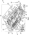
- the mold inserts 21, which each form a mold space 16 must always be placed exactly over one another, in order to ensure an exactly running miter surface 36. This positioning is described below on the basis of 4 to 6 will be explained in more detail, which show in a perspective view corresponding to a pressure-side half 39 and a closing-side half 40 of an injection molding tool in which the Oberschalendauerform 15, the Unterschalendauerform 17 and the Batterieiedeckeldauerform 35 are formed together.
- the mold inserts 21 of the corresponding permanent molds 15, 17 and 35 are held in the mold plates 41.
- the above-mentioned runners 34 are in the Fig. 4 and 5 with the view 33 in FIG Fig. 5 by an arrow in Fig. 4 is indicated.
- the sprue 34 of the upper shell mold 15 opens into a Stauboden 54 on the closing side half 40.
- Stauboden 54 collects to be processed primary material and is deflected so that the primary material emerges from the runner 34 for the to be manufactured upper shell 3 at an angle to its ejection direction , In this way, the runner 34 is performed as a tunnel gate and the upper shell duration form 15 as Abr disposg discernform.
- the halves 39, 40 are provided with a double centering.
- a first centering centered the two halves 39, 40 against each other roughly.
- Tool centering pin 47 screwed which engage in closing the mold space 16 in the corresponding Malawizentrieritn 48 on the closing side half 40.
- Form medicinalzentrierzapfen 49 are further formed on the mold inserts 21 on the pressure-side half, which can be inserted into Form medicinalzentrierabilityn 50 in the mold inserts 21 of the closing side half 40.
- the Form directlyzentierzapfen 49 are made smaller than the horrinum 47, so that when closing the mold cavity 16 first coarse centering acts, and only when it is largely completed, the fine centering is used.
- the sprue channels 34 and thus the injection points on central axes 51 of the mold spaces 16 are arranged so that the primary mold material after penetration into the respective mold space 16 can spread and distribute evenly there , In addition, this ensures that the primary molding material in the edge zones with the above jumps in the wall thickness 37, which form the miter surfaces 36, last penetrates and evenly fills these areas of the mold space 16. Furthermore, it is thus ensured that the primary molding material does not prematurely cure near the sprue channel 34 due to a too thin cavity area.
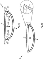
- the shells 3, 4 produced with the tool and method described above, after ejection from the tool in an in Fig. 6a indicated manner in a joining direction 52 are assembled to the plastic housing 2 and so a in Fig. 6b indicated interior 53 einhausen, in which, for example, a circuit board not shown can be added as electronics of the remote control 1.
- FIG Fig. 8a and 8b An example of an interior view of the manufactured upper shells 3 and lower shells 4 is correspondingly in FIG Fig. 8a and 8b shown. This corresponds to the view of Fig. 8a and 8b that which is formed with the closing half 40 of the tool molds.
- the ejector pins 27 and thus the bearing surfaces 55 are formed rectangular, wherein the broad side of the rectangular shape extends in the circumferential direction about the upper shell 3 or lower shell 4.
- the ejector pins 27 and thus the bearing surfaces 55 are arranged on an edge 53, directed towards the interior 53, of the upper shell 3 or lower shell 4. In this way it is ensured that the outer edges of the two shells 3, 4 close flush and so the monolithic appearance of the remote control is not disturbed.
- the shells 3, 4 can be recessed on the bearing surfaces 55.
- Fig. 8a and 8b are further correspondingly formed by the pin molding elements 42 and sleeve members 43 pin 42 'and sleeves 43' shown, of which for the sake of clarity, not all with a own reference signs are provided. Furthermore, in Fig. 8b to see the point 34 'at which the runner 34 for the lower shell 4 ended. The corresponding point 34 'on the upper shell is in the perspective of Fig. 8a not to be seen.
Abstract
Die Erfindung betrifft ein Kunststoffgehäuse (2) für elektronische Geräte (1), insbesondere Fernbedienungen, mit einem ersten Gehäuseteil (3) und einem zweiten Gehäuseteil (4), wobei das erste Gehäuseteil (3) eine in Richtung des zweiten Gehäuseteils (4) gerichtete Fügefläche (36) umfasst und das zweite Gehäuseteil (4) eine in Richtung des ersten Gehäuseteils (3) gerichtete Fügefläche (36) umfasst, wobei die beiden Gehäuseteile (3, 4) den Fügeflächen (36) aneinander anliegend zusammengesetzt sind, und wobei die Fügeflächen (36) als Gehrungsflächen (36) ausgeführt sind.The invention relates to a plastic housing (2) for electronic devices (1), in particular remote controls, with a first housing part (3) and a second housing part (4), wherein the first housing part (3) directed in the direction of the second housing part (4) Joining surface (36) and the second housing part (4) in the direction of the first housing part (3) directed joining surface (36), wherein the two housing parts (3, 4) the joining surfaces (36) are arranged adjacent to each other, and wherein the Joining surfaces (36) are designed as miter surfaces (36).
Description
Die vorliegende Erfindung betrifft ein Kunststoffgehäuse für elektronische Geräte, insbesondere Fernbedienungen.The present invention relates to a plastic housing for electronic devices, in particular remote controls.
Ein derartiges Kunststoffgehäuse ist beispielsweise aus der
Gemäß einem Aspekt der Erfindung, umfasst ein Kunststoffgehäuse für elektronische Geräte, insbesondere Fernbedienungen, ein erstes Gehäuseteil und ein zweites Gehäuseteil, wobei das erste Gehäuseteil eine in Richtung des zweiten Gehäuseteils gerichtete Fügefläche umfasst und das zweite Gehäuseteil eine in Richtung des ersten Gehäuseteils gerichtete Fügefläche umfasst, wobei die beiden Gehäuseteile den Fügeflächen aneinander anliegend zusammengesetzt sind, und wobei die Fügeflächen als Gehrungsflächen ausgeführt sind.According to one aspect of the invention, a plastic housing for electronic devices, in particular remote controls, comprises a first housing part and a second housing part, wherein the first housing part comprises a directed in the direction of the second housing part joining surface and the second housing part comprises a directed in the direction of the first housing part joining surface wherein the two housing parts are assembled to the joining surfaces adjacent to each other, and wherein the joining surfaces are designed as miter surfaces.
Dem angegebenen Kunststoffgehäuse liegt die Überlegung zugrunde, dass das eingangs genannte Kunststoffgehäuse Formschlusselemente aufweist, die die Fügefläche vergrößern und so den beiden Gehäuseteilen eine breitere Angriffsfläche gegeneinander bieten. Problematisch an den Formschlusselementen ist jedoch, dass diese exakt aufeinander abgestimmt werden müssen, weil sonst zwischen den beiden Gehäuseteilen im zusammengesetzten Zustand des Kunststoffgehäuses ein Spalt verbleibt, der vor allem in Bereichen mit hohen ästhetischen Anforderungen als störend empfunden werden kann. Um diesen Spalt zu vermeiden und zwischen den beiden Gehäuseteilen dennoch eine hohe Fügefläche zu realisieren, wird mit dem angegebenen Kunststoffgehäuse vorgeschlagen, die Fügeflächen als Gehrungsflächen auszuführen.The specified plastic housing is based on the consideration that the aforementioned plastic housing has form-locking elements that the Enlarge joining surface and thus offer the two housing parts a wider attack surface against each other. The problem with the interlocking elements, however, is that they must be matched exactly to one another, because otherwise a gap remains between the two housing parts in the assembled state of the plastic housing, which can be perceived as disturbing, especially in areas with high aesthetic requirements. In order to avoid this gap and still realize a high joining surface between the two housing parts, it is proposed with the specified plastic housing to perform the joining surfaces as Miter surfaces.
In einer Weiterbildung des angegebenen Kunstsstoffgehäuses sind die Gehrungsflächen der Gehäuseteile zumindest teilweise umlaufend um einen Innenraum ausgebildet, der eingerichtet ist, eine elektronische Komponente des elektronischen Gerätes einzuhausen. Auf diese Weise verlaufen die Gehrungsflächen V-förmig und erlauben es so, die beiden Gehäuseteile zusätzlich gegeneinander zu zentrieren. Damit erfüllen die Gehrungsflächen gleichzeitig die Funktion der zuvor genannten Formschlusselemente.In a further development of the specified plastic housing, the miter surfaces of the housing parts are at least partially formed circumferentially around an interior, which is adapted einhausen an electronic component of the electronic device. In this way, the miter surfaces are V-shaped and allow it to additionally center the two housing parts against each other. Thus, the miter surfaces simultaneously fulfill the function of the above-mentioned positive-locking elements.
In einer zusätzlichen Weiterbildung des angegebenen Kunststoffgehäuses sind die Gehrungsflächen in den Innenraum hinein führend ausgebildet. Auf diese Weise liegen alle stumpfen Kanten an den Gehäuseteilen, die durch die Gehrungsflächen gebildet werden im Innenraum des Kunststoffgehäuses. An den stumpfen Kanten können bei der Herstellung der Gehäuseteile Werkzeuge, wie beispielsweise Ausstoßerstifte, Entlüftungselemente oder dergleichen in besonders günstiger Weise innenraumseitig ansetzen, so dass eventuell verbleibende Grate oder dergleichen im Nachhinein nicht mehr sichtbar sind.In an additional development of the specified plastic housing, the miter surfaces are formed leading into the interior. In this way, all the blunt edges on the housing parts, which are formed by the miter surfaces in the interior of the plastic housing. At the blunt edges tools, such as ejector pins, vent elements or the like can apply in a particularly favorable manner on the interior side in the manufacture of the housing parts, so that any remaining burrs or the like are no longer visible in retrospect.
In einer anderen Weiterbildung wird das angegebene Kunststoffgehäuse durch ein Verfahren hergestellt, bei dem ein Urformmaterial in die die Gehäuseteile bildenden Formräume eingeführt und Luft aus dem den Formräumen an Eintlüftungsstellen abgeführt wird, die an oder neben Stellen in den Formräumen liegt, an der die Gehrungsflächen der Gehäuseteile gebildet werden.In another development, the specified plastic housing is produced by a method in which a primary molding material is introduced into the molding spaces forming the housing parts and air from the mold spaces at the ventilation points is discharged, which is located at or adjacent to places in the mold cavities, where the miter surfaces of the housing parts are formed.
Der Weiterbildung liegt die Überlegung zugrunde, dass das Urformmaterial beim Einführen in den Formraum die dort vorhandene Luft verdrängt, so dass die Luft aus dem Formraum abgeführt werden muss. Normalerweise wird die Luft aus dem Formraum an einer Trennebene zwischen den Werkzeugteilen abgeführt, die den Formraum bilden. Damit die Gehrungsflächen und damit die Formteile an der nach außen gerichteten Seite der Fernbedienung möglichst exakt spitz verlaufen, sollten die Trennebenen an dieser Stelle so dicht wie möglich sein, damit kein Urformmaterial in die Trennebene eintritt und so einen als störend wirkenden Grat hinterlässt. Durch diese dichte Ausführung der Trennebenen ist eine Entlüftung des Formraumes an der Trennebene praktisch ausgeschlossen. Daher wird vorgeschlagen, die Entlüftungsstelle an oder neben die Gehrungsfläche, vorzugsweise im zu bildenden Innenraum des Kunststoffgehäuses zu legen, damit die Entlüftung einerseits möglichst nah an der zu bildenden Gehrungsfläche stattfindet und sich so keine als störend empfundenen Verbrennungen, Einschlüsse oder dergleichen bilden können, andererseits aber auch herstellungsbedingte Grate oder dergleichen im zu bildenden Innenraum des Kunststoffgehäuses angeordnet werden.The further development is based on the consideration that the primary molding material displaces the air present there when it is introduced into the mold space, so that the air must be removed from the mold space. Normally, the air is removed from the mold space at a parting plane between the tool parts which form the mold space. So that the miter surfaces and thus the molded parts on the outwardly directed side of the remote control are as precisely pointed as possible, the parting planes should be as dense as possible at this point, so that no primary molding material enters the parting plane and thus leaves a burr acting as a disturbing. Due to this dense design of the parting planes, venting of the mold space at the parting plane is practically impossible. Therefore, it is proposed to place the venting point on or next to the miter surface, preferably in the interior of the plastic housing to be formed, so that the venting on the one hand takes place as close as possible to the miter surface to be formed and so can not be considered annoying burns, inclusions or the like, on the other but also production-related burrs or the like can be arranged in the interior of the plastic housing to be formed.
In einer Weiterbildung des angegebenen Verfahrens werden zum Abführen der Luft aus den Formräumen in die Formräume führende Kanäle genutzt, in denen Auswerferstifte eingeführt sind. Auf diese Weise wird einerseits der Luftkanal sehr klein gehalten, durch den die Luft aus dem Formraum abgeführt wird, so dass nach einer vollständigen Entlüftung des Formraumes auch entsprechend weniger Urformmaterial in den Entlüftungskanal eindringt. Andererseits wird der Entlüftungskanal beim Auswerfen des urgeformten Gehäuseteils automatisch durch den Auswerferstift gereinigt.In a further development of the specified method leading channels are used for discharging the air from the mold spaces in the mold spaces in which ejector pins are inserted. In this way, on the one hand the air duct is kept very small, through which the air is discharged from the mold space, so that after a complete venting of the mold space and correspondingly less primary material penetrates into the vent channel. On the other hand, the venting channel is automatically cleaned by the ejector pin when ejecting the urgeformten housing part.
In einer weiteren Weiterbildung des angegebenen Kunststoffgehäuses wird das Urformmaterial an Anspritzpunkten in die Formräume eingeführt, die an einer Seite des Formraumes angeordnet ist, der einer Seite mit der Entlüftungsstelle gegenüberliegt.In a further development of the specified plastic housing, the primary molding material is introduced at injection points in the mold spaces, which is arranged on one side of the mold space, which is opposite to a side with the venting point.
In einer besonderen Weiterbildung des angegebenen Kunststoffgehäuses sind die Anspritzpunkte in einer Anspritzrichtung des Urformmaterials gesehen mittig in den Formräumen angeordnet. Auf dieser Weise wird sichergestellt, dass sich das Urformmaterial gleichmäßig in alle Richtungen des Formraumes verteilen kann. Zusätzlich ist jedoch auch sicher gestellt, dass das Urformmaterial in die spitzen Bereiche des Formraumes zuletzt eindringt und so dort nicht vorzeitig aushärtet, was den Formraum verstopfen könnte.In a particular embodiment of the specified plastic housing, the injection points are arranged centrally in the mold spaces, as seen in a molding direction of the primary molding material. In this way it is ensured that the primary material can be distributed evenly in all directions of the mold space. In addition, however, it is also ensured that the primary molding material penetrates into the pointed areas of the mold cavity last and thus does not cure prematurely there, which could clog the mold cavity.
In einer noch anderen Weiterbildung des angegebenen Kunststoffgehäuses werden die Formräume mit Formplatten gebildet, die vor dem Einführen des Urformmaterials in die Formräume an einer Trennebene luftdicht verschlossen werden. Auf diese Weise wird der oben genannte Grat an der Trennebene im Formraum vermieden.In yet another further development of the specified plastic housing, the mold spaces are formed with mold plates which are hermetically sealed at a separating plane prior to the introduction of the primary mold material into the mold cavities. In this way, the above-mentioned burr at the parting plane in the mold space is avoided.
In einer bevorzugten Weiterbildung des angegebenen Kunststoffgehäuses münden die Gehrungsflächen der zu bildenden Gehäuseteile in die Trennebene.In a preferred embodiment of the specified plastic housing, the miter surfaces of the housing parts to be formed open into the parting plane.
In einer besonders bevorzugten Weiterbildung des angegebenen Kunststoffgehäuses liegen die Eintlüftungsstellen an den Gehrungsflächen der Trennebene gegenüber. Auf diese Weise ist sichergestellt, dass durch die Entlüftung entstehende Grate oder dergleichen im zu bildenden Innenraum des Kunststoffgehäuses angeordnet werden und von außen nicht sichtbar sind.In a particularly preferred development of the specified plastic housing, the ventilation points are located opposite the miter surfaces of the parting plane. In this way it is ensured that burrs or the like resulting from the venting are arranged in the interior of the plastic housing to be formed and are not visible from the outside.
Gemäß einem weiteren Aspekt der Erfindung wird in einem Verfahren zum Herstellen eines Gehäuseteiles, für eines der angegebenen Kunststoffgehäuse ein Urformmaterial in einen das Gehäuseteil bildenden Formraum eingeführt und Luft aus dem Formraum an einer Eintlüftungsstelle abgeführt, die an oder neben einer Stelle im Formraum liegt, an der die Gehrungsfläche des Gehäuseteils gebildet wird.According to a further aspect of the invention, in a method for producing a housing part, for one of the specified plastic housings, a primary molding material is introduced into a mold space forming the housing part, and air is introduced discharged from the mold space at a venting point, which is located at or adjacent to a point in the mold space at which the miter surface of the housing part is formed.
In einer Weiterbildung des angegebenen Verfahrens wird zum Abführen der Luft aus dem Formraum ein in den Formraum führender Kanal genutzt, in den ein Auswerferstift eingeführt ist.In a further development of the specified method, a channel leading into the forming space is used for discharging the air from the mold space, into which an ejector pin is introduced.
In einer anderen Weiterbildung des angegebenen Verfahrens wird das Urformmaterial an einem Anspritzpunkt in dem Formraum eingeführt, der an einer Seite des Formraumes angeordnet ist, der einer Seite mit der Entlüftungsstelle gegenüberliegt.In another embodiment of the specified method, the primary molding material is introduced at an injection point in the mold space, which is arranged on one side of the mold space, which is opposite to a side with the venting point.
In einer zusätzlichen Weiterbildung des angegeben Verfahrens der Anspritzpunkt dabei auf einer Mittelachse des Formraumes angeordnet.In an additional development of the stated method, the injection point is arranged on a central axis of the mold space.
In einer noch anderen Weiterbildung des angegebenen Verfahrens wird der Formraum über zwei Werkzeugformen gebildet, die vor dem Einführen des Urformmaterials in den Formraum an einer Trennebene luftdicht verschlossen werden.In yet another further development of the specified method, the mold space is formed by two tool molds which are hermetically sealed at a parting plane prior to introduction of the primary mold material into the mold space.
In einer besonderen Weiterbildung des angegebenen Verfahrens münden die Gehrungsfläche des zu bildenden Gehäuseteils in die Trennebene.In a particular embodiment of the specified method, the miter surface of the housing part to be formed open into the parting plane.
In einer besonders bevorzugten Weiterbildung des angegebenen Verfahrens liegt die Eintlüftungsstelle an der Gehrungsfläche der Trennebene gegenüber.In a particularly preferred embodiment of the specified method, the ventilation point is located opposite the miter surface of the parting plane.
Gemäß einem weiteren Aspekt der Erfindung ist ein Gehäuseteil eines der angegebenen Kunststoffgehäuse mit einem der angegebenen Verfahren hergestellt.According to a further aspect of the invention, a housing part of one of the specified plastic housing is produced by one of the stated methods.
Die oben beschriebenen Eigenschaften, Merkmale und Vorteile dieser Erfindung sowie die Art und Weise wie diese erreicht werden, werden verständlicher im Zusammenhang mit der folgenden Beschreibung der Ausführungsbeispiele, die im Zusammenhang mit der Zeichnung näher erläutert werden. Es zeigen:
-
Fig. 1 eine Fernbedienung in einer perspektivischen Ansicht, -
Fig. 2a bis 2c Ausschnitte von Schnittansichten eines Urformwerkzeuges zur Herstellung eines ersten Gehäuseteils für ein Kunststoffgehäuse der Fernbedienung derFig. 1 , -
Fig. 3a bis 3c Ausschnitte von Schnittansichten eines Urformwerkzeuges zur Herstellung eines zweiten Gehäuseteils für das Kunststoffgehäuse der Fernbedienung derFig. 1 , -
Fig. 4 eine perspektivische Ansicht eines Teils eines Urformwerkzeugs zur Herstellung des Kunststoffgehäuses für die Fernbedienung derFig. 1 , -
Fig. 5 eine Teilansicht des Teils des Urformwerkzeugs derFig. 4 aus einer anderen Perspektive, -
Fig. 6 eine perspektivische Ansicht eines weiteren Teils des Urformwerkzeugs zur Herstellung des Kunststoffgehäuses für die Fernbedienung derFig. 1 , -
Fig. 7a und 7b Schnittansichten des Kunststoffgehäuses der Fernbedienung derFig. 1 , und -
Fig. 8a und 8b Innenansichten entsprechend der Oberschale und der Unterschale des Kunststoffgehäuses der Fernbedienung derFig. 1 .
-
Fig. 1 a remote control in a perspective view, -
Fig. 2a to 2c Cutouts of sectional views of a mold tool for producing a first housing part for a plastic housing of the remote control ofFig. 1 . -
Fig. 3a to 3c Cutouts of sectional views of a master tool for producing a second housing part for the plastic housing of the remote control ofFig. 1 . -
Fig. 4 a perspective view of a portion of a molding tool for producing the plastic housing for the remote control ofFig. 1 . -
Fig. 5 a partial view of the part of the original mold of theFig. 4 from a different perspective, -
Fig. 6 a perspective view of another part of the molding tool for producing the plastic housing for the remote control ofFig. 1 . -
Fig. 7a and 7b Section views of the plastic housing of the remote controlFig. 1 , and -
Fig. 8a and 8b Interior views according to the upper shell and the lower shell of the plastic housing of the remote controlFig. 1 ,
In den Figuren werden gleiche technische Elemente mit gleichen Bezugszeichen versehen und nur einmal beschrieben. Die Figuren sind rein schematisch und geben vor allem nicht die tatsächlichen geometrischen Verhältnisse wieder.In the figures, the same technical elements are provided with the same reference numerals and described only once. The figures are purely schematic and above all not reflect the actual geometric conditions.
Es wird auf
Die Fernbedienung 1 umfasst ein Kunststoffgehäuse 2, das aus einem ersten Gehäuseteil in Form einer Oberschale 3 und einem zweiten Gehäuseteil Unterschale 4 zusammengesetzt ist, sowie zwei Tastenfelder 5 mit einer Vielzahl von Tastenelementen 6. Von den Tastenelementen 6 im Tastenfeld 5 sind in den Figuren der Übersichtlichkeit halber nicht alle mit einem Bezugszeichen versehen.The remote control 1 comprises a
Zwischen den beiden Tastenfeldern 5 ist ein Steuerkreuz 8 angeordnet, das ein erstes Tastenelement 9, ein zweites Tastenelement 10, ein drittes Tastenelement 11 und ein viertes Tastenelement 12 umfasst. Die vier Tastenelemente 9 bis 12 sind umfänglich und im Abstand von 90° um eine Bestätigungstaste 13 angeordnet. Das Steuerkreuz 8 mit den vier Tastenelementen 9 bis 12 ist hier als kreisrunde Scheibe ausgebildet. Ferner sind auf der Fernbedienung 1 Rückmeldeelemente 14 in Form kleiner Lämpchen angeordnet, die in Abhängigkeit eines Tastendruckes auf der Fernbedienung 1 aufleuchten können.Between the two
Mit der Fernbedienung 1 soll der Betrieb des beispielhaften Multimediagerätes gesteuert werden. Hierzu gibt ein Benutzer mittels der Tasten 5 auf der Oberschale 3 der Fernbedienung 1 Steuerbefehle als Informationen in die Fernbedienung 1 ein, die dann mittels eines nicht weiter gezeigten Übertragers an das zu steuernde elektronische Gerät übertragen werden. Ein derartiger Befehl kann beispielsweise als Richtungsbefehl über die Tastenelemente 9 bis 12 eingegeben werden, der dann die Bewegung eines Steuerelementes auf dem beispielhaften Multimediagerät in eine der vier möglichen Bewegungsrichtungen steuert.With the remote control 1, the operation of the exemplary multimedia device is to be controlled. For this purpose, a user by means of the
Die Abbildung der Fernbedienung 1 ist lediglich beispielhaft, um die nachstehenden technischen Ausführungen besser verständlich zu gestalten. Sie lassen sich jedoch an jedem beliebigen elektronischen Gerät und insbesondere an jeder beliebigen Fernbedienung umsetzen.The illustration of the remote control 1 is merely exemplary in order to better understand the following technical explanations. However, they can be implemented on any electronic device and in particular on any remote control.
Das Kunststoffgehäuse 2 wird durch Urformen hergestellt, das in den nachstehenden technischen Ausführungen anhand des Spritzgusses erläutert werden soll. In den
Die Oberschalendauerform 15 umfasst eine Druckseite 18, die auch Düsenseite 18 genannt wird. Der Druckseite 18 gegenüberliegen umfasst die Oberschalendauerform 15 eine Schließseite 19, die auch Auswerferseite 19 genannt wird. Druckseitig 18 und schließseitig 19 wird die Oberschalendauerform 15 von zwei Aufspannplatten 20 eingeschlossen, auf denen die restlichen Elemente der Oberschalendauerform 15 getragen sind.The
Druckseitig 18 ist auf der Aufspannplatte 20 eine in
Schließseitig 19 ist auf der Aufspannplatte 20 ein Auswerfergehäuse 23 getragen, das auf der der Aufspannplatte 20 gegenüberliegenden Seite mit einer Druckplatte 24 verschlossen ist. Auf der Druckplatte 24 ist eine in
Die Matrix 22 und der Kern 25 bilden zusammen den Oberschalenformraum 16. In den Oberschalenformraum 16 führen durch die Druckplatte 24 und den schließseitigen Formeinsatz 21 Führungskanäle 26, in denen Auswerferstifte 27 geführt sind. Die Führungskanäle 26 weisen dabei Schultern 28 auf, an denen die Auswerferstifte 27 mit entsprechenden Gegenschultern 29 anschlagen könnten. Von den Schultern 28 und Gegenschultern 29 sind in den
Die Auswerferstifte 27 sind auf einer Auswerfergrundplatte 30 getragen und in ihrer Lage durch eine Auswerferhalteplatte 31 positioniert. Die beiden Platten 30, 31 sind im Inneren des Auswerfergehäuses 23 beweglich angeordnet, so dass über diese die Auswerferstiftte 27 bewegt werden können.The ejector pins 27 are carried on an
Durch die Druckplatten 21 verlaufen auf der Druckseite 18 als auch auf der Schließseite 19 Temperierbohrungen 32, durch die ein Temperiermittel, wie beispielsweise Wasser geführt werden kann, um den Oberschalenformraum 16 zu durch Kühlen oder Heizen temperieren. Von diesen Temperierbohrungen 32 sind der Übersichtlichkeit halber nicht alle mit einem Bezugszeichen versehen. Die Temperierbohrungen 32 weisen dabei einen Mindestabstand vom Formraum 16 auf, der 10 bis 20 mal kleiner ist, als eine Breite der Oberschale 3 des Kunststoffgehäuses 2. Für den Mindestabstand wurden in der vorliegenden Ausführung 2mm gewählt. Der Durchmesser der Temperierbohrungen 32 ist zwischen 4 und 5 mal so groß, wie der Mindestabstand. Das wären in der vorliegenden Ausführung zwischen 8mm und 10mm. Je größer die Temperierbohrungen 32 sind, desto schneller erfolgt die Temperierung.By the
Die Unterschalendauerform 17 ist in der selben Weise aufgebaut, wie die Oberschalendauerform 15. Deshalb sind in den
Der einzige Unterschied zur Oberschalendauerform 15 ist, dass in der nicht gezeigten Formplatte der Unterschalendauerform 17 auf der Druckseite 18 zwei Formeinsätze 21 eingesetzt sind, die entsprechend mehrere Temperierbohrungen 32 in die Unterschalendauerform 17 einführen.The only difference to the
Die Oberschalendauerform 15 und die Unterschalendauerform 17 können gemeinsam mit einer weiteren, in
Zur Herstellung einer Oberschale 3 und/oder einer Unterschale 4 wird ein variothermes Spritzgussverfahren angewendet. Während üblicherweise beim Spritzguss, insbesondere von Kunststoff unter der Temperierung eine Kühlung verstanden wird, um die Wärmeenergie des geschmolzenen Urformmaterials abzuführen, wird der Formraum 16 bei einem variothermen Spritzgussverfahren vor dem Einspritzen des Urformmaterials zunächst aufgeheizt und danach wieder abgekühlt. Hierbei wird in der vorliegenden Ausführung der Formeinsatz 21 auf der Druckseite 18 als auch auf der Schließseite 19 gleich temperiert, das heißt zunächst aufgewärmt. Auf diese Weise wird insbesondere beim Spritzgießen von Hochglanz-Gehäuseteilen 3, 4 sichergestellt, dass am fertigen Produkt keine Bindenähte auftreten.For producing an
Unabhängig vom Aufwärmen wird der entsprechende Formraum 16 geschlossen. Hierzu wird die Aufspannplatte 20 auf der Schließseite 19 gegen die Aufspannplatte 20 auf der Druckseite 18 bewegt, bis sich die beiden Formplatten 21, in denen entsprechend die Matrix 20 und der Kern 25 ausgebildet ist, berühren.Regardless of the warm-up, the corresponding
Ist der Formraum 16 geschlossen und entsprechend aufgewärmt, wird das aufgeheizte Urformmaterial über einen in
Das in den Formraum 16 eingeführte Urformmaterial verteilt sich dort und verdrängt die dort vorhandene Luft. Diese muss dementsprechend abgeführt werden, worauf an späterer Stelle näher eingegangen wird.The primary mold material introduced into the
Ist der Formraum 16 vollständig mit Urformmaterial ausgefüllt, werden die Formeinsätze 21 über die Temperierbohrungen 32 wieder abgekühlt, so dass sich das Urformmaterial verfestigt. Hierzu wird beispielsweise kaltes Wasser durch die Temperierbohrungen 32 getrieben.If the
Im Anschluss daran wird der Formraum 16 geöffnet und das so gefertigte Formteil über die Auswerferstifte 27 aus dem Werkzeug ausgestoßen. Hierzu drückt die Auswerfergrundplatte 30 die Auswerferstifte 27 gegen den geöffneten Formraum 16, so dass sich das dort gefertigte Formteil, also die Oberschale 3 oder die Unterschale 4 löst und so aus dem Werkzeug herausfallen kann. Im Anschluss werden die Auswerferstifte 27 von der Auswerferhalteplatte 31 wieder zurückgezogen, und das gesamte Werkzeug wieder in den Ausgangszustand zurückversetzt, damit der Spritzgußvorgang erneut gestart werden kann.Following this, the
In der vorliegenden Ausführung soll das Kunststoffgehäuse 2 der Fernbedienung 1 ein möglichst monolithisches Aussehen erhalten. Wenn die Oberschale 3 und die Unterschale 4 daher an einer Fügefläche 36 zusammengesetzt werden, dann soll eine Stoßfuge zwischen den beiden Schalen 3, 4 auf eine Kante fallen, so dass zwischen den beiden Schalen 3, 4 möglichst kein Spalt sichtbar ist. Auf diese Weise wäre es für den Betrachter kaum erkennbar, ob es sich bei dem Kunststoffgehäuse 2 der Fernbedienung 1 um ein einteiliges oder um ein mehrteiliges Bauteil handelt. Die Fernbedienung 1 erhält auf diese Weise ein deutlich schlankeres Aussehen, insbesondere dann, wenn die Oberschale 3 in einem farblichen Kontrast zur Unterschale 4 ausgeführt wird.In the present embodiment, the
Um dies zu erreichen, werden die Fügeflächen 36 an den beiden Schalen 3, 4 derart ausgeführt, dass die beiden Schalen 3, 4 über eine Gehrungsverbindung miteinander verbunden werden können. Daher sollen die Fügeflächen 36 nachstehend als Gehrungsflächen 36 bezeichnet werden. Bei der Herstellung der Gehrungsflächen 36 ist jedoch zu beachten, dass hierdurch an den zu fertigenden Schalen 3, 4 Sprünge in deren Wandstärke 37 auftreten, die zu Fehlern in den Oberflächen der zu fertigenden Schalen 3, 4 führen können. Um den oben genannten monolitischen Effekt bestmöglichst erreichen zu können, müssen die Schalen 3, 4 an den Gehrungsflächen 36 jedoch möglichst spitz zulaufen. Dies bedingt, dass die Wandstärke 37 von einer Normalwandstärke von beispielsweise 2mm auf eine Wandstärke von unter 0,2mm abfällt. Daher muss beim Einsatz des zuvor erläuterten Spritzgussverfahrens darauf geachtet werden, dass aufgrund der großen Sprünge in der Wandstärke 37 die Bildung von Oberflächenfehler, wie Verbrennungen an den Schalen 3, 4 nicht begünstigt wird.To achieve this, the joining
Grundsätzlich kann zu der oben genannten Entlüftung des Formraumes 16 eine Trennebene 38 zwischen den Formeinsätzen verwendet werden. Hierzu müsste jedoch in der Trennebene ein Spalt verbleiben, durch den die Luft aus dem Formraum 16 nach außen entweichen kann. Ist der Formraum 16 jedoch vollständig entlüftet, dann dringt anschließend Urformmaterial dorthin ein, was zur Bildung von Graten führt. Diese Grate kontradiktieren jedoch insbesondere das gewünschte monolithische Erscheinungsbild des Kunststoffgehäuses 2, weshalb eine Entlüftung über die Trennebene 38 ausscheidet.In principle, a separating
Aus diesem Grund sind in der vorliegenden Ausführung die Auswerferstifte 27 im Bereich der Gehrungsflächen 36 zur Innenseite des zu fertigenden Kunstoffgehäuses 2 hin angeordnet. Die Führungskanäle 26 und die Auswerferstifte 27 können so derart ausgeführt werden, dass ein ausreichender Spalt zwischen ihnen verbleibt, über den der Formraum 16 entlüftet werden kann.For this reason, the ejector pins 27 are arranged in the region of the miter surfaces 36 to the inside of the
Vorteil an dieser Lösung ist, dass beim Auswerfen des gefertigten Formteils, also einer der Schalen 3, 4 auch gleichzeitig die Führungskanäle 26 durch die Bewegung der Auswerferstifte 27 gereinigt werden. Zudem kann die Luft beim Auswerfen des gefertigten Formteils aus den Führungskanälen 26 wieder entweichen.The advantage of this solution is that when ejecting the finished molded part, ie one of the
Weiterhin müssen die Formeinsätze 21, die jeweils einen Formraum 16 bilden stets exakt übereinandergesetzt werden, um eine exakt verlaufende Gehrungsfläche 36 zu gewährleisten. Diese Positionierung soll nachstehend anhand der
In den Kernen 22 der Formeinsätze 21 der schließseitigen Hälfte 40 sind weitere Details zu erkennen, die zur Herstellung der Schalen 3, 4 dienen. So sind beispielsweise in
Weiter sind in
Die oben genannten Angusskanäle 34 sind in den
Um die zuvor genannte exakte Lage der Formeinsätze 21 und damit die exakte Ausbildung der Formräume 16 sicherzustellen, sind die Hälften 39, 40 mit einer doppelten Zentrierung versehen. Eine erste Zentrierung zentriert die beiden Hälften 39, 40 gegeneinander grob. Hierzu sind an der druckseitigen Hälfte 39 Werkzeugzentrierzapfen 47 angeschraubt, die beim Schließen des Formraumes 16 in entsprechende Werkzeugzentrieraufnahmen 48 an der schließseitigen Hälfte 40 eingreifen. Zur Feinzentrierung sind ferner an den Formeinsätzen 21 an der druckseitigen Hälfte 39 Formeinsatzzentrierzapfen 49 ausgebildet, die in Formeinsatzzentrieraufnahmen 50 in den Formeinsätzen 21 der schließseitigen Hälfte 40 einführbar sind.In order to ensure the aforementioned exact position of the mold inserts 21 and thus the exact formation of the
Die Formeinsatzzentrierzapfen 49 sind dabei kleiner ausgeführt, als die Werkzeugzentrierzapfen 47, so dass beim Schließen des Formraumes 16 zunächst die grobe Zentrierung wirkt, und erst wenn diese weitestgehend abgeschlossen ist, die Feinzentrierung zum Einsatz kommt.The
Zur weiteren Reduktion von potentiellen Oberflächenfehlern auf den Schalen 3, 4 des Kunststoffgehäuses 2 werden die Angusskanäle 34 und damit die Anspritzpunkte auf Mittelachsen 51 der Formräume 16 angeordnet, so dass das Urformmaterial nach dem Eindringen in den jeweiligen Formraum 16 sich dort gleichmäßig ausbreiten und verteilen kann. Zudem ist dadurch sichergestellt, dass das Urformmaterial in die Randzonen mit den oben genannten Sprüngen in der Wandstärke 37, die die Gehrungsflächen 36 bilden, zuletzt vordringt und diese Bereiche des Formraumes 16 gleichmäßig ausfüllt. Weiterhin ist so sichergestellt dass das Urformmaterial nahe des Angusskanals 34 aufgrund eines zu dünnen Formraumbereichs nicht vorzeitig aushärtet.To further reduce potential surface defects on the
Die mit dem zuvor beschriebenen Werkzeug und Verfahren hergestellten Schalen 3, 4 können nach dem Auswerfen aus dem Werkzeug in einer in
Beim Zusammensetzen von Oberschale 3 und Unterschale 4 in der Fügerichtung 52 werden die beiden Schalen 3, 4 dabei an den Gehrungsflächen 36 automatisch zentriert. Auf diese Weise sind ein in
Ein Beispiel für eine Innenansicht der hergestellten Oberschalen 3 und Unterschalen 4 ist entsprechend in
Deutlich zu sehen sind Auflageflächen 55, an denen die Auswerferstifte 27 angreifen, um entsprechend die Oberschale 3 oder Unterschale 4 aus der schließseitgen Hälfte 40 auszustoßen. Die Auswerferstifte 27 und damit die Auflageflächen 55 sind rechteckförmig ausgebildet, wobei die Breitseite der Rechteckform sich in Umfangsrichtung um die Oberschale 3 oder Unterschale 4 erstreckt.Clearly visible are bearing
Die Auswerferstifte 27 und damit die Auflageflächen 55 sind an einer zum Innenraum 53 hin gerichteten Kante 56 der Oberschale 3 oder Unterschale 4 angeordnet. Auf diese Weise wird sichergestellt, dass die Außenkanten der beiden Schalen 3, 4 bündig schließen und so das monolithische Erscheinungsbild der Fernbedienung nicht gestört wird.The ejector pins 27 and thus the bearing surfaces 55 are arranged on an
Durch die Auswerferstifte 27 können die Schalen 3, 4 an den Auflageflächen 55 vertieft sein.By the ejector pins 27, the
In den
Claims (14)
Applications Claiming Priority (3)
| Application Number | Priority Date | Filing Date | Title |
|---|---|---|---|
| DE102015016784.7A DE102015016784B4 (en) | 2015-12-23 | 2015-12-23 | Monolithic remote control and method of making the same |
| PCT/EP2016/082031 WO2017108862A2 (en) | 2015-12-23 | 2016-12-20 | Monolithic remote control |
| EP16815857.4A EP3393753B1 (en) | 2015-12-23 | 2016-12-20 | Monolithic remote control |
Related Parent Applications (2)
| Application Number | Title | Priority Date | Filing Date |
|---|---|---|---|
| PCT/EP2016/082031 Previously-Filed-Application WO2017108862A2 (en) | 2015-12-23 | 2016-12-20 | Monolithic remote control |
| EP16815857.4A Division EP3393753B1 (en) | 2015-12-23 | 2016-12-20 | Monolithic remote control |
Publications (2)
| Publication Number | Publication Date |
|---|---|
| EP3527353A2 true EP3527353A2 (en) | 2019-08-21 |
| EP3527353A3 EP3527353A3 (en) | 2019-12-04 |
Family
ID=57589050
Family Applications (2)
| Application Number | Title | Priority Date | Filing Date |
|---|---|---|---|
| EP16815857.4A Active EP3393753B1 (en) | 2015-12-23 | 2016-12-20 | Monolithic remote control |
| EP19164688.4A Pending EP3527353A3 (en) | 2015-12-23 | 2016-12-20 | Monolithic remote control |
Family Applications Before (1)
| Application Number | Title | Priority Date | Filing Date |
|---|---|---|---|
| EP16815857.4A Active EP3393753B1 (en) | 2015-12-23 | 2016-12-20 | Monolithic remote control |
Country Status (16)
| Country | Link |
|---|---|
| US (2) | US20210166893A1 (en) |
| EP (2) | EP3393753B1 (en) |
| JP (1) | JP6951360B2 (en) |
| CN (1) | CN108602281A (en) |
| CA (1) | CA3009260C (en) |
| DE (1) | DE102015016784B4 (en) |
| DK (1) | DK3393753T3 (en) |
| ES (1) | ES2737448T3 (en) |
| HK (1) | HK1256114A1 (en) |
| HR (1) | HRP20191255T1 (en) |
| HU (1) | HUE044626T2 (en) |
| LT (1) | LT3393753T (en) |
| PL (1) | PL3393753T3 (en) |
| PT (1) | PT3393753T (en) |
| SI (1) | SI3393753T1 (en) |
| WO (1) | WO2017108862A2 (en) |
Cited By (2)
| Publication number | Priority date | Publication date | Assignee | Title |
|---|---|---|---|---|
| EP3906771A1 (en) | 2020-05-07 | 2021-11-10 | CLAAS Selbstfahrende Erntemaschinen GmbH | Agricultural machine |
| EP3906773A1 (en) | 2020-05-07 | 2021-11-10 | CLAAS Selbstfahrende Erntemaschinen GmbH | Agricultural machine with hybrid drive unit comprising an engergy storage, wherein the state of charge of the energy storage is controlled based on a prediction of the expected work load |
Families Citing this family (1)
| Publication number | Priority date | Publication date | Assignee | Title |
|---|---|---|---|---|
| DE102021127425A1 (en) | 2021-10-21 | 2023-04-27 | Fm Marketing Gmbh | Unbreakable electrical hand-held device, in particular remote control |
Citations (1)
| Publication number | Priority date | Publication date | Assignee | Title |
|---|---|---|---|---|
| DE102010045944A1 (en) | 2010-09-21 | 2012-03-22 | Fm Marketing Gmbh | Plastic housing for electronic devices, in particular for remote controls |
Family Cites Families (15)
| Publication number | Priority date | Publication date | Assignee | Title |
|---|---|---|---|---|
| GB1376733A (en) | 1972-10-11 | 1974-12-11 | Scintillant Ltd | Decorative article or plaything |
| JPS62152823A (en) * | 1985-12-27 | 1987-07-07 | Toyoda Gosei Co Ltd | Vacuum molding |
| JPH064622Y2 (en) * | 1986-06-20 | 1994-02-02 | 三洋電機株式会社 | Remote control transmitter case |
| DE3821433A1 (en) | 1988-06-24 | 1989-12-28 | Altenhofen Hermann Josef | THREE-DIMENSIONAL PUZZLE |
| US5893959A (en) * | 1994-03-31 | 1999-04-13 | Marquardt Gmbh | Workpiece of plastic and production process for such a workpiece |
| WO2000000337A1 (en) * | 1998-06-26 | 2000-01-06 | Asahi Glass Company Ltd. | Method and device for manufacturing transparent plate with frame |
| JP4078499B2 (en) * | 1998-06-26 | 2008-04-23 | 旭硝子株式会社 | Method for producing transparent plate with frame and mold for producing transparent plate with frame |
| EP1108519B1 (en) * | 1999-12-13 | 2006-08-16 | Fuji Photo Film Co., Ltd. | Molding method of and injection mould for manufacturing a cassette half. |
| US6877974B2 (en) * | 2000-12-22 | 2005-04-12 | Acushnet Company | Split vent pin for injection molding |
| US7008240B1 (en) * | 2004-04-16 | 2006-03-07 | Super Talent Electronics, Inc. | PC card assembly |
| JP2006326974A (en) * | 2005-05-25 | 2006-12-07 | Toshiba Corp | Mold assembly |
| US9044898B2 (en) * | 2012-04-03 | 2015-06-02 | Apple Inc. | Methods for joining electronic device housing structures using heat activated thermoset film |
| DE102013207668A1 (en) * | 2013-04-26 | 2014-10-30 | Bayerische Motoren Werke Aktiengesellschaft | Tool for producing a fiber-plastic composite component with at least one vent hole and arranged therein Auswerferstift |
| DE102013018870A1 (en) * | 2013-11-12 | 2015-05-13 | Kraussmaffei Technologies Gmbh | Device for producing a molded part in a molding tool of a machine for producing plastic molded parts |
| CN205596480U (en) * | 2016-04-28 | 2016-09-21 | 嘉兴福气多温控床有限公司 | Remote controller |
-
2015
- 2015-12-23 DE DE102015016784.7A patent/DE102015016784B4/en not_active Expired - Fee Related
-
2016
- 2016-12-20 WO PCT/EP2016/082031 patent/WO2017108862A2/en active Application Filing
- 2016-12-20 CA CA3009260A patent/CA3009260C/en active Active
- 2016-12-20 PT PT16815857T patent/PT3393753T/en unknown
- 2016-12-20 SI SI201630330T patent/SI3393753T1/en unknown
- 2016-12-20 JP JP2018552125A patent/JP6951360B2/en active Active
- 2016-12-20 US US16/065,283 patent/US20210166893A1/en not_active Abandoned
- 2016-12-20 CN CN201680068517.1A patent/CN108602281A/en active Pending
- 2016-12-20 HU HUE16815857 patent/HUE044626T2/en unknown
- 2016-12-20 DK DK16815857.4T patent/DK3393753T3/en active
- 2016-12-20 PL PL16815857T patent/PL3393753T3/en unknown
- 2016-12-20 EP EP16815857.4A patent/EP3393753B1/en active Active
- 2016-12-20 EP EP19164688.4A patent/EP3527353A3/en active Pending
- 2016-12-20 LT LTEP16815857.4T patent/LT3393753T/en unknown
- 2016-12-20 ES ES16815857T patent/ES2737448T3/en active Active
-
2018
- 2018-11-27 HK HK18115191.5A patent/HK1256114A1/en unknown
-
2019
- 2019-07-12 HR HRP20191255TT patent/HRP20191255T1/en unknown
-
2022
- 2022-08-15 US US17/887,991 patent/US20220392718A1/en active Pending
Patent Citations (1)
| Publication number | Priority date | Publication date | Assignee | Title |
|---|---|---|---|---|
| DE102010045944A1 (en) | 2010-09-21 | 2012-03-22 | Fm Marketing Gmbh | Plastic housing for electronic devices, in particular for remote controls |
Cited By (5)
| Publication number | Priority date | Publication date | Assignee | Title |
|---|---|---|---|---|
| EP3906771A1 (en) | 2020-05-07 | 2021-11-10 | CLAAS Selbstfahrende Erntemaschinen GmbH | Agricultural machine |
| EP3906773A1 (en) | 2020-05-07 | 2021-11-10 | CLAAS Selbstfahrende Erntemaschinen GmbH | Agricultural machine with hybrid drive unit comprising an engergy storage, wherein the state of charge of the energy storage is controlled based on a prediction of the expected work load |
| DE102020112451A1 (en) | 2020-05-07 | 2021-11-11 | Claas Selbstfahrende Erntemaschinen Gmbh | Agricultural work machine |
| DE102020112433A1 (en) | 2020-05-07 | 2021-11-11 | Claas Selbstfahrende Erntemaschinen Gmbh | Agricultural work machine |
| US11622504B2 (en) | 2020-05-07 | 2023-04-11 | Claas Selbstfahrende Erntemaschinen Gmbh | Agricultural production machine |
Also Published As
| Publication number | Publication date |
|---|---|
| EP3393753A2 (en) | 2018-10-31 |
| EP3393753B1 (en) | 2019-04-24 |
| WO2017108862A3 (en) | 2017-08-17 |
| DK3393753T3 (en) | 2019-07-22 |
| CN108602281A (en) | 2018-09-28 |
| PL3393753T3 (en) | 2020-03-31 |
| SI3393753T1 (en) | 2019-11-29 |
| LT3393753T (en) | 2019-08-26 |
| DE102015016784A1 (en) | 2017-06-29 |
| JP6951360B2 (en) | 2021-10-20 |
| DE102015016784B4 (en) | 2018-12-20 |
| HK1256114A1 (en) | 2019-09-13 |
| EP3527353A3 (en) | 2019-12-04 |
| CA3009260A1 (en) | 2017-06-29 |
| US20220392718A1 (en) | 2022-12-08 |
| JP2019511886A (en) | 2019-04-25 |
| WO2017108862A2 (en) | 2017-06-29 |
| CA3009260C (en) | 2023-11-28 |
| HUE044626T2 (en) | 2019-11-28 |
| HRP20191255T1 (en) | 2019-10-18 |
| US20210166893A1 (en) | 2021-06-03 |
| PT3393753T (en) | 2019-08-05 |
| ES2737448T3 (en) | 2020-01-14 |
Similar Documents
| Publication | Publication Date | Title |
|---|---|---|
| DE3037252C2 (en) | Injection mold for the production of moldings from two types of plastic | |
| EP3393753B1 (en) | Monolithic remote control | |
| EP1813404B1 (en) | Moulding tool | |
| WO2019214815A1 (en) | Method for producing a sole of a shoe, in particular of a sports shoe | |
| CH624603A5 (en) | ||
| DE10231551A1 (en) | Molding tool for plastic housing parts | |
| EP3727723A1 (en) | Method for producing a moulded part and feeder insert for use in such a method | |
| EP2134528B1 (en) | Moulding tool with a modular construction comprising a frame | |
| DE1911600C3 (en) | Multi-part mold for pressing or blowing thermoplastic materials | |
| DE102009031604A1 (en) | Sand casting tool for producing sand casting product, comprises first and second molded parts, which are movable relative to each other in direction to Z-axis and have first and second mold recesses, and nozzle- and/or smooth pressing unit | |
| EP1741531A1 (en) | Mould for the production of a ceramic heat shield elements | |
| DE102007001756B4 (en) | Method and injection mold for injection molding of hollow molded plastic parts | |
| DE102010018114B4 (en) | Process for the production of components by means of polymer or plastic casting or fiber composite plastics | |
| DE102011116258A1 (en) | Method for manufacturing multiple components, involves injecting injection enables material into cavity for forming die cast component with cooling time-determining maximum thickness | |
| DE10000580A1 (en) | Production of a writing instrument front part with a one-piece deformation | |
| DE10034519C1 (en) | Production of keyboard keys, for e.g. a computer keyboard, comprise a printed thermoplastic sheet inserted into a mold after the dies have shaped the cores and caps to be pressed between them | |
| EP1046486B1 (en) | Mould tool for producing a plurality of parts mounted by injection moulding | |
| DE102012102008A1 (en) | Device for injection molding of plastic parts of semi-spherical segments of spherical reflective body, has movement device moving cutting plate such that aperture surrounding cutting edge crosses edge of recess on front side of main body | |
| DE19615309A1 (en) | Injection moulding and joining of objects formed by two separate sections | |
| EP2714361B1 (en) | Process and device for production of film decorated plastic parts with through holes or deep recesses with imd-injection | |
| DE102016100970A1 (en) | Method for producing a plastic component and plastic component | |
| EP4311649A1 (en) | Insulating element and system and method for producing same | |
| DE102019127972A1 (en) | INJECTION MOLD WITH A SIDE INJECTION NOZZLE | |
| DE4235776A1 (en) | Plastic tool for moulding plastic components and tool mfr. - has recesses for ejector unit created in tool by locating formers in mould used to cast plastic tool | |
| WO2015032489A1 (en) | Cold runner melt distributor |
Legal Events
| Date | Code | Title | Description |
|---|---|---|---|
| PUAI | Public reference made under article 153(3) epc to a published international application that has entered the european phase |
Free format text: ORIGINAL CODE: 0009012 |
|
| STAA | Information on the status of an ep patent application or granted ep patent |
Free format text: STATUS: THE APPLICATION HAS BEEN PUBLISHED |
|
| AC | Divisional application: reference to earlier application |
Ref document number: 3393753 Country of ref document: EP Kind code of ref document: P |
|
| AK | Designated contracting states |
Kind code of ref document: A2 Designated state(s): AL AT BE BG CH CY CZ DE DK EE ES FI FR GB GR HR HU IE IS IT LI LT LU LV MC MK MT NL NO PL PT RO RS SE SI SK SM TR |
|
| PUAL | Search report despatched |
Free format text: ORIGINAL CODE: 0009013 |
|
| AK | Designated contracting states |
Kind code of ref document: A3 Designated state(s): AL AT BE BG CH CY CZ DE DK EE ES FI FR GB GR HR HU IE IS IT LI LT LU LV MC MK MT NL NO PL PT RO RS SE SI SK SM TR |
|
| RIC1 | Information provided on ipc code assigned before grant |
Ipc: H01H 9/02 20060101ALI20191029BHEP Ipc: B29C 45/40 20060101ALN20191029BHEP Ipc: B29C 65/00 20060101AFI20191029BHEP |
|
| STAA | Information on the status of an ep patent application or granted ep patent |
Free format text: STATUS: REQUEST FOR EXAMINATION WAS MADE |
|
| 17P | Request for examination filed |
Effective date: 20200604 |
|
| RBV | Designated contracting states (corrected) |
Designated state(s): AL AT BE BG CH CY CZ DE DK EE ES FI FR GB GR HR HU IE IS IT LI LT LU LV MC MK MT NL NO PL PT RO RS SE SI SK SM TR |
|
| STAA | Information on the status of an ep patent application or granted ep patent |
Free format text: STATUS: EXAMINATION IS IN PROGRESS |
|
| 17Q | First examination report despatched |
Effective date: 20211221 |