EP3526443B1 - Downhole devices, associated apparatus and methods - Google Patents
Downhole devices, associated apparatus and methods Download PDFInfo
- Publication number
- EP3526443B1 EP3526443B1 EP17787549.9A EP17787549A EP3526443B1 EP 3526443 B1 EP3526443 B1 EP 3526443B1 EP 17787549 A EP17787549 A EP 17787549A EP 3526443 B1 EP3526443 B1 EP 3526443B1
- Authority
- EP
- European Patent Office
- Prior art keywords
- fluid
- signal
- generating material
- control mechanism
- flow control
- Prior art date
- Legal status (The legal status is an assumption and is not a legal conclusion. Google has not performed a legal analysis and makes no representation as to the accuracy of the status listed.)
- Active
Links
- 238000000034 method Methods 0.000 title claims description 26
- 239000012530 fluid Substances 0.000 claims description 160
- 239000000463 material Substances 0.000 claims description 120
- 230000007246 mechanism Effects 0.000 claims description 65
- 230000004044 response Effects 0.000 claims description 48
- 230000004913 activation Effects 0.000 claims description 37
- 238000012544 monitoring process Methods 0.000 claims description 21
- 238000004891 communication Methods 0.000 claims description 16
- XLYOFNOQVPJJNP-UHFFFAOYSA-N water Substances O XLYOFNOQVPJJNP-UHFFFAOYSA-N 0.000 claims description 16
- 239000000470 constituent Substances 0.000 claims description 4
- 230000007423 decrease Effects 0.000 claims description 4
- 230000001788 irregular Effects 0.000 claims description 3
- 239000002071 nanotube Substances 0.000 claims description 3
- 238000011144 upstream manufacturing Methods 0.000 claims description 3
- VYPSYNLAJGMNEJ-UHFFFAOYSA-N Silicium dioxide Chemical compound O=[Si]=O VYPSYNLAJGMNEJ-UHFFFAOYSA-N 0.000 description 12
- 238000004519 manufacturing process Methods 0.000 description 12
- 230000000694 effects Effects 0.000 description 9
- 239000003112 inhibitor Substances 0.000 description 8
- 239000000377 silicon dioxide Substances 0.000 description 6
- 230000015572 biosynthetic process Effects 0.000 description 4
- 239000000203 mixture Substances 0.000 description 4
- 239000002245 particle Substances 0.000 description 4
- 230000003068 static effect Effects 0.000 description 4
- 238000003860 storage Methods 0.000 description 4
- 238000003306 harvesting Methods 0.000 description 3
- 238000002955 isolation Methods 0.000 description 3
- 238000005259 measurement Methods 0.000 description 3
- 230000000717 retained effect Effects 0.000 description 3
- 239000003990 capacitor Substances 0.000 description 2
- 230000000977 initiatory effect Effects 0.000 description 2
- 239000002086 nanomaterial Substances 0.000 description 2
- 239000004215 Carbon black (E152) Substances 0.000 description 1
- 230000017488 activation-induced cell death of T cell Effects 0.000 description 1
- 230000003466 anti-cipated effect Effects 0.000 description 1
- 238000012512 characterization method Methods 0.000 description 1
- 239000011248 coating agent Substances 0.000 description 1
- 238000000576 coating method Methods 0.000 description 1
- 230000000295 complement effect Effects 0.000 description 1
- 239000003989 dielectric material Substances 0.000 description 1
- 229930195733 hydrocarbon Natural products 0.000 description 1
- 125000001183 hydrocarbyl group Chemical group 0.000 description 1
- 238000011065 in-situ storage Methods 0.000 description 1
- 239000007924 injection Substances 0.000 description 1
- 238000002347 injection Methods 0.000 description 1
- 239000012212 insulator Substances 0.000 description 1
- 230000035699 permeability Effects 0.000 description 1
- 230000008569 process Effects 0.000 description 1
- 238000012545 processing Methods 0.000 description 1
- 230000011664 signaling Effects 0.000 description 1
Images


Classifications
-
- E—FIXED CONSTRUCTIONS
- E21—EARTH OR ROCK DRILLING; MINING
- E21B—EARTH OR ROCK DRILLING; OBTAINING OIL, GAS, WATER, SOLUBLE OR MELTABLE MATERIALS OR A SLURRY OF MINERALS FROM WELLS
- E21B34/00—Valve arrangements for boreholes or wells
- E21B34/06—Valve arrangements for boreholes or wells in wells
- E21B34/066—Valve arrangements for boreholes or wells in wells electrically actuated
-
- E—FIXED CONSTRUCTIONS
- E21—EARTH OR ROCK DRILLING; MINING
- E21B—EARTH OR ROCK DRILLING; OBTAINING OIL, GAS, WATER, SOLUBLE OR MELTABLE MATERIALS OR A SLURRY OF MINERALS FROM WELLS
- E21B47/00—Survey of boreholes or wells
- E21B47/10—Locating fluid leaks, intrusions or movements
-
- E—FIXED CONSTRUCTIONS
- E21—EARTH OR ROCK DRILLING; MINING
- E21B—EARTH OR ROCK DRILLING; OBTAINING OIL, GAS, WATER, SOLUBLE OR MELTABLE MATERIALS OR A SLURRY OF MINERALS FROM WELLS
- E21B41/00—Equipment or details not covered by groups E21B15/00 - E21B40/00
- E21B41/0085—Adaptations of electric power generating means for use in boreholes
-
- E—FIXED CONSTRUCTIONS
- E21—EARTH OR ROCK DRILLING; MINING
- E21B—EARTH OR ROCK DRILLING; OBTAINING OIL, GAS, WATER, SOLUBLE OR MELTABLE MATERIALS OR A SLURRY OF MINERALS FROM WELLS
- E21B47/00—Survey of boreholes or wells
- E21B47/10—Locating fluid leaks, intrusions or movements
- E21B47/113—Locating fluid leaks, intrusions or movements using electrical indications; using light radiations
-
- E—FIXED CONSTRUCTIONS
- E21—EARTH OR ROCK DRILLING; MINING
- E21B—EARTH OR ROCK DRILLING; OBTAINING OIL, GAS, WATER, SOLUBLE OR MELTABLE MATERIALS OR A SLURRY OF MINERALS FROM WELLS
- E21B47/00—Survey of boreholes or wells
- E21B47/12—Means for transmitting measuring-signals or control signals from the well to the surface, or from the surface to the well, e.g. for logging while drilling
- E21B47/125—Means for transmitting measuring-signals or control signals from the well to the surface, or from the surface to the well, e.g. for logging while drilling using earth as an electrical conductor
-
- E—FIXED CONSTRUCTIONS
- E21—EARTH OR ROCK DRILLING; MINING
- E21B—EARTH OR ROCK DRILLING; OBTAINING OIL, GAS, WATER, SOLUBLE OR MELTABLE MATERIALS OR A SLURRY OF MINERALS FROM WELLS
- E21B49/00—Testing the nature of borehole walls; Formation testing; Methods or apparatus for obtaining samples of soil or well fluids, specially adapted to earth drilling or wells
- E21B49/08—Obtaining fluid samples or testing fluids, in boreholes or wells
- E21B49/087—Well testing, e.g. testing for reservoir productivity or formation parameters
-
- G—PHYSICS
- G01—MEASURING; TESTING
- G01N—INVESTIGATING OR ANALYSING MATERIALS BY DETERMINING THEIR CHEMICAL OR PHYSICAL PROPERTIES
- G01N27/00—Investigating or analysing materials by the use of electric, electrochemical, or magnetic means
- G01N27/60—Investigating or analysing materials by the use of electric, electrochemical, or magnetic means by investigating electrostatic variables, e.g. electrographic flaw testing
-
- G—PHYSICS
- G01—MEASURING; TESTING
- G01N—INVESTIGATING OR ANALYSING MATERIALS BY DETERMINING THEIR CHEMICAL OR PHYSICAL PROPERTIES
- G01N33/00—Investigating or analysing materials by specific methods not covered by groups G01N1/00 - G01N31/00
- G01N33/26—Oils; Viscous liquids; Paints; Inks
- G01N33/28—Oils, i.e. hydrocarbon liquids
- G01N33/2823—Raw oil, drilling fluid or polyphasic mixtures
-
- G—PHYSICS
- G01—MEASURING; TESTING
- G01V—GEOPHYSICS; GRAVITATIONAL MEASUREMENTS; DETECTING MASSES OR OBJECTS; TAGS
- G01V3/00—Electric or magnetic prospecting or detecting; Measuring magnetic field characteristics of the earth, e.g. declination, deviation
- G01V3/18—Electric or magnetic prospecting or detecting; Measuring magnetic field characteristics of the earth, e.g. declination, deviation specially adapted for well-logging
-
- H—ELECTRICITY
- H02—GENERATION; CONVERSION OR DISTRIBUTION OF ELECTRIC POWER
- H02N—ELECTRIC MACHINES NOT OTHERWISE PROVIDED FOR
- H02N1/00—Electrostatic generators or motors using a solid moving electrostatic charge carrier
- H02N1/04—Friction generators
-
- E—FIXED CONSTRUCTIONS
- E21—EARTH OR ROCK DRILLING; MINING
- E21B—EARTH OR ROCK DRILLING; OBTAINING OIL, GAS, WATER, SOLUBLE OR MELTABLE MATERIALS OR A SLURRY OF MINERALS FROM WELLS
- E21B34/00—Valve arrangements for boreholes or wells
- E21B34/06—Valve arrangements for boreholes or wells in wells
- E21B34/063—Valve or closure with destructible element, e.g. frangible disc
-
- E—FIXED CONSTRUCTIONS
- E21—EARTH OR ROCK DRILLING; MINING
- E21B—EARTH OR ROCK DRILLING; OBTAINING OIL, GAS, WATER, SOLUBLE OR MELTABLE MATERIALS OR A SLURRY OF MINERALS FROM WELLS
- E21B43/00—Methods or apparatus for obtaining oil, gas, water, soluble or meltable materials or a slurry of minerals from wells
- E21B43/02—Subsoil filtering
- E21B43/08—Screens or liners
-
- E—FIXED CONSTRUCTIONS
- E21—EARTH OR ROCK DRILLING; MINING
- E21B—EARTH OR ROCK DRILLING; OBTAINING OIL, GAS, WATER, SOLUBLE OR MELTABLE MATERIALS OR A SLURRY OF MINERALS FROM WELLS
- E21B49/00—Testing the nature of borehole walls; Formation testing; Methods or apparatus for obtaining samples of soil or well fluids, specially adapted to earth drilling or wells
- E21B49/08—Obtaining fluid samples or testing fluids, in boreholes or wells
- E21B49/087—Well testing, e.g. testing for reservoir productivity or formation parameters
- E21B49/0875—Well testing, e.g. testing for reservoir productivity or formation parameters determining specific fluid parameters
-
- G—PHYSICS
- G01—MEASURING; TESTING
- G01N—INVESTIGATING OR ANALYSING MATERIALS BY DETERMINING THEIR CHEMICAL OR PHYSICAL PROPERTIES
- G01N13/00—Investigating surface or boundary effects, e.g. wetting power; Investigating diffusion effects; Analysing materials by determining surface, boundary, or diffusion effects
- G01N13/02—Investigating surface tension of liquids
- G01N2013/0216—Investigating surface tension of liquids by measuring skin friction or shear force
Definitions
- Some described examples relate to downhole devices, associated apparatus and methods. In some cases, those devices, etc., are specifically for use in an oil and gas environment and perform downhole tasks, such as monitoring fluids, generating energy, signalling and the like.
- ICDs Inflow control devices
- AICDs autonomously
- control devices typically the ability with which fluid can flow through such control devices is affected by the composition or state of that fluid.
- Such autonomous devices may be preferred in some applications because they obviate the need for operational user input, or continual monitoring and response to varying production conditions, etc. That said, there is a continuing need to improve the ability with which such flow control devices can operate autonomously and/or with improved accuracy, especially when they are to be installed in remote locations.
- downhole devices, methods and other apparatus which may be used to generate energy, monitor fluids and/or provide control signals or otherwise trigger for actuation.
- the devices, methods, etc. may provide improved autonomy and/or accuracy, while at the same time minimise any effect on the operation of a well.
- Such devices and method may be particularly useful downhole and in remote locations.
- WO 2015/094147 A1 teaches that flow electrification sensors and methods relating thereto may be useful in characterizing fluids, especially the in situ characterization of fluids produced during oil and gas production operations.
- An example of such a system may include a flow path; a flow electrification sensor at least partially contained within the flow path, the flow electrification sensor comprising a static charge accumulator and an insulator arranged such that the static charge accumulator interacts with a fluid in the flow path; a reference sensor; and a signal processor communicably coupled to the flow electrification sensor and the reference sensor.
- US 2012/273234 A1 (Cornette ) teaches processes (methods) for harnessing flowinduced electrostatic energy in an oil and/or gas well and using this energy to power electrical devices (e.g., flowmeters, electrically-actuated valves, etc.) downhole.
- electrical devices e.g., flowmeters, electrically-actuated valves, etc.
- US 2011/210645 A1 (Mason ) teaches a downhole static power generator that comprises a static charge accumulator comprising a dielectric material having a surface to contact a flowing dielectric fluid.
- US 2012/228876 A1 (Samuel ) teaches a system to harvest energy from fluid flow including: an outer body including a flow way; an inner sleeve rotatably coupled to the outer body; and a magnetostrictive material disposed proximate to the inner sleeve to be strained due to a rotation of the inner sleeve in response to a fluid flow in the flow way.
- US2009/101341 A1 (Baker Hughes ) teaches an apparatus for controlling a flow of fluid in a well including a flow control device and a generator that generates electrical energy in response to a flow of an electrically conductive fluid.
- the flow control device may include an actuator receiving electrical energy from the generator, and a valve operably coupled to the actuator.
- the actuator may be configured to operate after a preset value for induced voltage is generated by the generator.
- the generator may use a pair of electrodes positioned along a flow path of the electrically conductive fluid to generate electrical energy.
- one or more elements positioned proximate to the electrodes generate a magnetic field along the flow path of the electrically conductive fluid that causes the electrodes to generate a voltage.
- the electrodes create an electrochemical potential in response to contact with the electrically conductive fluid.
- the devices and associated method uses a generating material having a fluid contact surface.
- a contact surface is configured to be in contact with a fluid downhole, for example a flowing fluid.
- the generating material is configured to generate an electric charge at the material in response a fluid at the contact surface (e.g. flowing fluid).
- the device further comprises a signal source configured to provide a signal in response to a generated electric charge at the generating material.
- the generating material is configured to generate an electric charge in response to a fluid at the contact surface.
- the generating material may be configured to generate triboelectric charge in response to a fluid at the contact surface, e.g. flowing fluid.
- the generating material may be configured to generate surface charge in response to fluid at the contact surface.
- the generating material may be configured to generate an electric charge in response to a fluid at the contact surface using multiple charge effects.
- the signal source may be configured to provide a fluid monitoring signal, e.g. a data signal or otherwise signal intended to communicate information, in response to a generated electric charge at the generating material.
- a fluid monitoring signal e.g. a data signal or otherwise signal intended to communicate information
- the contact surface may be configured to be in contact with a fluid to be monitored.
- the generating material may be configured to generate an electric charge in response to a property to be monitored of a fluid at the contact surface.
- the fluid monitoring signal may correspond to those "to-be-monitored" fluid properties of the fluid at the contact surface.
- the device may be specifically configured to monitor for one expected fluid property.
- the generating material may be specifically selected/configured based on that expected fluid property to be monitored.
- a signal from the signal source may provide information relating to the measurement - or otherwise monitoring - of that fluid property in the fluid at the contact surface.
- the device may be specifically configured to monitor for the presence (or indeed the extent of the presence) of a constituent fluid of a fluid at the contact surface.
- that constituent fluid to be monitored may be one of water, oil or gas - as may be expected in a production well, for example.
- the device may be specifically configured to monitor for (or otherwise measure) the water cut, i.e. percentage of water composition, of any fluid flowing at the contact surface.
- the signal source may be configured to provide a fluid monitoring signal in response to a generated electric charge at the generating material corresponding to the water cut of the fluid.
- the device may be configured additionally or alternatively to monitor other fluid properties, such as temperatures, pressures, flow rates, viscosities, pH, etc. Such properties may be used for flow metering, or the like.
- the generating material may comprise one or more defined flow paths along which fluid can flow against, or otherwise be in contact with, the contact surface.
- the flow path(s) may comprise channels formed through the generating material, and through which fluid can flow.
- the channels may be defined by regular and/or irregular structures in the material, such as structured tubes, and/or interstitially connected voids or the like (e.g. open cells).
- the generating material may be formed, or comprise micro/nanomaterials or structures, for example nanotubes, particles (e.g. agglomerated particles), or the like.
- the channels may have a narrowest cross-sectional area of in the range of 1 nm 2 to 1 mm 2 .
- the channels may have an effective length of from around 10 mm to 50 mm or the like, or indeed longer.
- the generating material may have an effective contact surface area of around 1 m 2 , or greater.
- the flow paths may be formed so as to provide a maximum area of contact surface, e.g. for a minimum or an acceptable pressure drop across the device, or indeed generating material (e.g. for an expected fluid flowing at the contact surface).
- the device may comprise a plurality of alternatively structured flow paths through that material, which may help optimise the contact surface area, while reducing pressure drop.
- the generating material may have an effective permeability and/or porosity that is similar to or the same as a well formation in the region at which the device is expected to be positioned.
- the generating material may comprise silica (e.g. comprising silica particulates).
- the silica particulates may be formed in a complementary manner to an expected formation at the intended location for the device.
- the generating material may comprise a single charge-generating material based on intended application. Otherwise, the generating material may comprise multiple charge-generating materials. In those cases, each of the charge generating materials may be configured to provide different charge in response to fluid properties at the contact surface (e.g. different charge for different fluid properties).
- the generating material may be specifically configured to communicate electrically-generated charge from the material to one or more conduction paths for further use (e.g. for use at the signal output).
- the conduction paths may be formed solely or principally within the generating material, while in other examples the conduction paths may be formed when fluid is flowing or otherwise present at the contact surface.
- the device may be specifically configured such that fluid may form part of the conduction path for charge from the generating material.
- a signal may be provided directly from electric charge generated as a result of fluid at the contact surface (e.g. a current signal directly from any conduction path).
- the signal may relate to accumulated charge potential in the material.
- the signal source may directly use the charge being generated in the generating material for the purposes of a signal.
- the device may comprise a charge storage device (e.g. battery, capacitor, etc.) configured to provide power to the signal source from time to time, e.g. upon request.
- a charge storage device e.g. battery, capacitor, etc.
- the device may comprise a processor module.
- the processor module may be configured to receive or measure electric charge being generated in the material, and to provide signal (e.g. a data signal, such as a fluid monitoring signal) to the signal source for further communication.
- the processor module may comprise a processor, memory, etc. configured in a known manner.
- the processor module may comprise a power source.
- the processor module may comprise an amplifier or the like.
- the signal provided at the signal source is directly provided from charge generated at the material (e.g. a current signal) or whether the signal is initially processed, then in either case the signal may comprise information relating to the fluid properties of the fluid at the contact surface.
- That signal may be communicated to a further location (e.g. surface), or otherwise that signal may be communicated for further use downhole.
- the device may be configured to generate energy downhole.
- the generating material may be configured (e.g. optimally configured) to generate the electric charge based on the expected fluid properties/conditions downhole.
- the device may be configured such that electric charge generated at the generating material is permitted to flow (e.g. directly flow) to the signal source so as to provide a power signal.
- That power signal may be usable to provide power to a further downhole device, and/or a power supply (e.g. a battery), or the like.
- the signal may be communicated to a power storage device.
- a power storage device may comprise a battery, such a trickle charge battery, or capacitor, or the like.
- the downhole device may comprise that downhole power storage device.
- the downhole device comprises a downhole mechanism, tool, or the like, in communication with the signal source. That mechanism may be configured to operate responsive to signals being provided from the signal source. For example, the device may be configured to provide a control signal (e.g. the signal source may provide a trigger signal for the downhole mechanism when a particular generated electric charge indicates certain fluid properties).
- a control signal e.g. the signal source may provide a trigger signal for the downhole mechanism when a particular generated electric charge indicates certain fluid properties.
- the downhole mechanism comprises a flow control mechanism.
- the flow control mechanism is configured to operate (e.g. activate/deactivate) on the basis of a signal being provided at the signal source and in response to a generated electric charge at the generating material.
- the flow control mechanism comprises a valve member configured to control fluid flow by increasing, reducing, initiating and/or discontinuing a flow of flowing fluid.
- the valve member may be operable between an open position in which flow is permitted and a closed position in which the flow is inhibited or prevented from flowing.
- valve member In a closed position, the valve member may be positioned or retained against a valve seat in order to seal and prevent fluid flow.
- flow control mechanism may be configured to partially open or close the valve member in order to restrict flow (e.g. choke).
- the flow control mechanism comprises an activation device.
- the activation device is in communication with the signal source.
- the activation device may be configured to operate (e.g. open/close) the valve member in the event of a particular signal being received from the signal source.
- the activation device may comprise an energisable element (e.g. switch, magnet, or the like) configured to retain/release the valve to a particular position.
- the activation device comprises a retainer, configured to retain the valve in a particular configuration.
- the activation device is configured to activate upon receipt of a particular signal from the signal source. Activation of the activation device may allow the valve member to move between open and closed positions.
- the activation device may comprise a biasing mechanism, configured to assist with operable opening/closing of the valve member in the event of a received signal from the signal source.
- the biasing mechanism may comprise a spring, or the like, in order to urge the valve member to an open or closed position accordingly.
- the device is configured such that, flow of charge from the signal source - which may directly generated from the generating material - is used to activate the activation device.
- the activation device comprises an electrically conducting portion. Current (e.g. the flow of electrical charge) from the signal output may be configured to pass through the conducting portion. When the rate of charge flowing through the conducting portion exceeds at particular threshold, the structural integrity of that portion of the activation device decreases to an extent to allow the valve to open/close.
- the activation device comprises a sacrificial element configured to retain the valve in a particular position
- the biasing mechanism and sacrificial element are specifically configured together to cause opening/closing of the valve member when a particular threshold current is provided or exceeded from the signal source. That threshold may relate to a particular monitored fluid property (e.g. water cut). In other words, the device may be configured such that when the fluid property is observed, the flow control mechanism operates.
- the flow control mechanism may be configured as a flapper valve or the like.
- the operable closing of the value may restrict or inhibit flow along a tubing (e.g. producing tubing).
- the flow control mechanism may be configured as an inflow control device (e.g. together with wellbore completion, or the like). In those examples, operable closing of the value may restrict or inhibit flow from a wellbore or annulus to the production tubing.
- the flow control mechanism may be provided in a housing having an inlet in fluid communication with the wellbore or annulus and an outlet in fluid communication with tubing.
- the generating material may be provided at the inlet such that fluid flowing over the contact surface of the generating material, to the tubing, via the flow control mechanism.
- a filter such as a sandscreen or the like, may be provided upstream of the generating material.
- the device may comprise an activation inhibitor.
- an activation inhibitor may prevent fluid be it, or otherwise flowing over, the contact surface.
- Such an activation inhibitor may be configured to provide a time-delay for activation, e.g. after deployment. Such inhibitor may be removed via intervention means.
- the method comprises providing fluid at a contact surface of a generating material so as to generate an electric charge in response that fluid.
- the method may comprise providing a signal in response to a generated electric charge at the generating material.
- the method may comprise generating a triboelectric charge in response to a fluid at the contact surface, e.g. flowing fluid at the contact surface.
- the method may comprise generating surface charge in response to fluid at the contact surface.
- the method may comprise generating an electric charge in response to a fluid at the contact surface using multiple charge effects.
- the method may comprise providing a fluid monitoring signal in response to a generated electric charge at the generating material.
- the contact surface may be configured to be in contact with a fluid to be monitored.
- the generating material may be configured to generate an electric charge in response to a property of a fluid at the contact surface.
- the fluid monitoring signal may correspond to fluid properties of the fluid at the contact surface.
- the method may comprise additionally or alternatively providing a power signal in response to a generated electric charge at the generating material.
- That power signal may be usable to provide power to a further downhole device, and/or a power supply (e.g. a trickle-charge battery), or the like.
- the method comprises activing a downhole mechanism in response to receipt of a signal (e.g. triggering a downhole mechanism).
- That downhole mechanism comprises a flow control mechanism.
- a downhole device comprising:
- a downhole method comprising:
- the invention includes one or more corresponding aspects, embodiments or features in isolation or in various combinations whether or not specifically stated (including claimed) in that combination or in isolation.
- features associated with particular recited embodiments relating to devices may be equally appropriate as features of embodiments relating specifically to methods of operation or use, and vice versa.
- one or more embodiments/aspects may be useful in effective monitoring fluids, generating energy, providing downhole control (e.g. autonomous control) and the like.
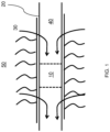
- Figure 1 shows a simplified representation of a horizontal section of a completed well 20.
- production fluids 30 enter a tubular 40 (e.g. production tubing) from a hydrocarbon-bearing formation 50 for communication to surface (not shown for ease).
- tubular 40 e.g. production tubing
- hydrocarbon-bearing formation 50 for communication to surface (not shown for ease).
- downhole devices 10 are deployed either as part of the completion, or subsequently in order to collect data, perform control operations, or the like.
- such devices 10 are positioned at remote locations (e.g. remote from surface), and there is a continuing desire to be able to minimise energy usage or at least be able to harvest energy so as to power downhole sensors, equipment, etc., with minimum effect on the operation of a well. Further, there is a desire for such devices 10 to be able to operate with improved autonomy and/or accuracy (e.g. when monitoring condition), especially when they are to be installed in such remote locations.
- FIG 2 shows an example of a downhole device 100 that may be deployed in a wellbore (e.g. as in Figure 1 ).
- the device 100 is comprised with a section of production tubing 110 configured to produce fluids to surface, in a known manner.
- the device 100 comprises a generating material 120 that is specifically configured to generate electric charge when interacting with the fluid 130 (e.g. product).
- the material comprises a contact surface that is configured to be in contact with the fluid 130.
- the material 120 is formed in annular manner on the inner surface of the tubing 110. As such, an aperture 140 permits some flow of fluid along the tubing 110, without contacting the material 120. In some examples, that need not be the case, and the material 120 may extend entirely across the tubing. It will also be appreciated, given the following description, that in some examples the material 120 may be retained within a support structure, or the like. In other cases, the material may be provided as a coating or the like, for example.
- the material 120 itself is formed of, or comprises micro/nanomaterials or structures, for example nanotubes, particles (e.g. agglomerated particles), etc.
- a number of defined flow paths are provided along which fluid can flow and be in contact with the contact surface.
- Those flow paths comprise channels formed through the generating material 120 itself, and through which fluid 130 can flow (i.e. in addition to through the aperture 140).
- the channels 125 may be defined by regular and/or irregular structures in the material, such as structured tubes, and/or interstitially connected voids or the like (e.g. open cells).
- the channels may have a narrowest cross-sectional area of in the range of 1 nm 2 to 1 mm 2 .
- the channels may have an effective length of from around 10 mm to 50 mm or the like, or indeed longer.
- the effective contact surface area of the generating material may be around 1 m 2 , or greater.
- the flow paths may formed so as to provide a maximum area of contact surface at the material, but for an acceptable pressure drop across the device 100, or indeed generating material 120 (e.g. for an expected fluid flowing at the contact surface).
- the material 120 is specifically configured to generate an electric charge, and in this example a triboelectric charge, in response a fluid 130 flowing at the contact surface formed by the flow paths.
- a triboelectric charge in response to a fluid 130 flowing at the contact surface formed by the flow paths.
- the generating material may be configured to generate surface charge in response to fluid at the contact surface, or indeed be configured to generate an electric charge in response to a fluid at the contact surface using multiple charge effects (e.g. combination of triboelectric, surface, etc.).
- the generating material may for example, comprise silica. Some properties of silica may be useful in monitoring for the presence of water. Further, the characteristic properties of silica may be known for downhole environments. That said, other materials may be used as appropriate and depending on application.
- the material 120 may comprise a single charge-generating material based on intended application, or otherwise comprise multiple charge-generating materials (e.g. as an assembly). In those cases, each of the charge generating materials 120 may be configured to provide different charge in response to fluid properties at the contact surface (e.g. different charge for different fluid properties). Further, those different materials 120 may provide different generating effects (e.g. surface charge, triboelectric, or the like).
- the generating material 120 may be specifically configured to communicate electrically-generated charge from the material 120 to one or more conduction paths for further use (e.g. for use at a signal output).
- the conduction paths are formed solely or principally within the generating material 120, while in other examples the conduction paths may be formed when fluid is flowing at the contact surface. In other similar words, the flowing fluid may form part of the conduction path for charge from the generating material 120.
- the device 100 further comprises a signal source 150 configured to provide a signal in response to a generated electric charge at the generating material 120 (e.g. and communicated via the conduction paths).
- That signal may be a power signal and/or data signal (including a control signal), as will be explained.
- the signal source 150 is configured to provide a signal directly from any electric charge generated as a result of fluid flowing (e.g. directly from any conduction path).
- the signal source 150 may be considered to use directly the charge being generated in the generating material 120 for the purposes of a signal.
- the generating material 120 may be selected and configured (e.g. optimally configured) to generate the optimal electric charge based on an expected fluid property of the fluid 130.
- the device 100 - and the signal source - may be configured to provide a power signal usable to provide power to further downhole devices 160.
- Such devices 160 may include, for example, downhole mechanisms, actuators, sensors, or indeed power supplies (e.g. batteries).
- the device 100 may be configured to trickle charge existing downhole power supplies, or systems.
- the device 100 may be specifically configured to provide a fluid monitoring signal, e.g. a data signal, in response to a generated electric charge at the generating material 120.
- the generation material 120 may be configured to generate a particular electric charge in response to a particular property of a fluid flowing at the contact surface.
- the fluid monitoring signal may correspond to fluid properties of the fluid at the contact surface.
- the device 100 can be specifically configured and calibrated to monitor for one expected fluid property, and the components of the device 100 can be selected based on the desired performance of the material for that fluid property, during anticipated operational conditions. In such cases, the generating material 120 may be selected based on that expected fluid property to be monitored.
- a signal from the signal source 150 can provide information relating to the measurement - or otherwise monitoring - of that fluid property in the fluid at the contact surface.
- the device 100 is specifically configured to monitor for the presence (or indeed the extent of the presence) of a constituent fluid of a fluid at the contact surface, e.g. water cut - that is the percentage of water composition of any fluid flowing at the contact surface.
- a constituent fluid of a fluid at the contact surface e.g. water cut - that is the percentage of water composition of any fluid flowing at the contact surface.
- the output at the signal source 150 e.g. a current signal or charge held at the material 120
- the device 100 can be calibrated for expected water cut (or other fluid property to be monitored) such that the fluid monitoring is provided essentially by the magnitude of the current flow or the observed potential charge stored at the material. That current flow/electric potential can be used as a data signal relating to fluid properties. That data signal may be communicated to surface, and/or other downhole equipment and devices, as needed. In some cases, the signal may be used as a trigger (e.g. when exceeding a particular threshold).
- the device 100 may be configured additionally or alternatively to monitor other fluid properties, such as pressures, temperatures, flow rates, viscosities, pH, etc. Such properties may assist with, or be used in relation to other measurements, such as flow metering, or the like.
- the device 100 may comprise a processor module 200 in order to provide the signal to the signal source.
- FIG 2b shows the device 100 comprising such a module 200, together with the module 200 itself in Figure 2c .
- the processor module 200 may be configured to receive or measure electric charge being generated in the material 120, as above.
- the processor module 200 may comprise a processor 210, memory 220, configured in a known manner.
- the processor module 200 may comprise a power source 230, as well as other signal processing components as necessary.
- the signal source may be in communication with further downhole apparatus, or surface, or the like, in order to communicate a data signal relating to the monitoring of fluid.
- charge generated at the material may power the module 200 as well as be used for any subsequent signal.
- the device 100 may be used to generate energy for a further downhole device, or provide a data signal for monitoring fluids, etc.
- the device may additionally comprise a downhole mechanism, in communication with the signal source, and configured to operate responsive to signals being provided from the signal source.
- the downhole device 100 may be considered, in some cases, to provide a control signal or otherwise trigger for actuation.
- the device 100 comprises a flow control mechanism 300, which in this case is exemplified as a flapper valve or the like.
- the signal source 150 is in communication with the flow control mechanism 300 such that the flow control mechanism 300 operates (e.g. activates/deactivates) on the basis of a signal being provided at the signal source 150, and in response to a generated electric charge at the generating material 120.
- the flow control mechanism 300 comprises a value member 310 configured to control fluid flow by increasing, reducing, initiating and/or discontinuing a flow of flowing fluid.
- the valve member 310 is operable between an open position in which flow is permitted and a closed position in which the flow is inhibited or prevented from flowing.
- the value member 310 may be positioned or retained against a valve seat (not shown) in order to seal and prevent fluid flow.
- the flow control mechanism 300 may be configured to partially open or close the valve member 310 in order to restrict flow (e.g. choke).
- the flow control mechanism 300 comprises an activation device 320, which is communication with the signal source 150.
- the activation device 320 may comprise a retainer 325 configured to retain the valve in a particular position (in this case, open).
- the activation device 320 further comprises a biasing mechanism 327, configured to assist with operable closing of the valve member 310 in the event of a received signal from the signal source.
- the biasing mechanism 327 may comprise a spring, or the like, in order to urge the valve member to an open or closed position accordingly (in this example, closed).
- the retainer 325 is specifically configured such that current (e.g. the flow of electrical charge) from the signal output may be configured to pass through a conducting portion of the retainer 325.
- the retainer 325 is considered to be or comprise sacrificial element.
- the biasing mechanism 327 and retainer 325 may be specifically configured together to cause opening/closing of the valve member 310 when a particular threshold signal is provided or exceeded from the signal source. That threshold may relate to a particular monitored fluid property (e.g. water cut).
- the activation device may comprise an energisable element (e.g. magnet) configured to retain/release the valve to a particular position, or the like.
- the activation device of the fluid control mechanism may be operable using logic signals provided from the signal source.
- fluid control mechanism 300 is shown as a flapper valve, or the like, it will be appreciated that in other examples, the fluid control mechanism 300 may be provided as an inflow control device. In such cases, the downhole device 100 may be provided together with wellbore completion.
- FIG. 4 shows a similar downhole device 100, but having an alternative flow control mechanism 400.
- the mechanism comprises a valve member 410, in the form of a plate, and a valve seat 415, in order to seal and prevent fluid flow when desired.
- Operable closing of the value member 410 can be used restrict or inhibit flow from a wellbore or annulus to the tubing 40.
- the flow control mechanism 410 is provided in a housing having an inlet 440 in fluid communication with the wellbore and an outlet 450 in fluid communication with tubing 40.
- the generating material 120 is provided at the inlet 440 such that fluid flowing from the wellbore flows over the contact surface of the generating material 120, to the tubing 40, via the flow control mechanism 400.
- a filter 460 such as a sandscreen or the like, may be provided upstream of the generating material 120.
- the flow control mechanism 400 comprises an activation device 420, which is communication with the signal source 150.
- the activation device 420 comprises again retainers 425 (e.g. sacrificial elements, in the form of as a fuses) that are configured to retain the valve member 410 in a particular position (in this case, open).
- the activation device 420 again further comprises a biasing mechanism 427, configured to assist with operable closing of the valve member 410 in the event of a received signal from the signal source 150.
- the biasing mechanism 427 and retainer 425 may be specifically configured together to cause opening/closing of the valve member 410 when a particular threshold signal is provided or exceeded from the signal source. That threshold may relate to a particular monitored fluid property (e.g. water cut). As such, the production of water can be accurately and autonomously minimised.
- the device 100 may comprise an activation inhibitor.
- an activation inhibitor may prevent flow of fluid over the contact surface.
- Such an activation inhibitor may be configured to provide a time-delay for activation, e.g. after deployment. Such inhibitor may be removed via intervention means.
- flowing fluid at the contact surface of the generating material is used to generate an electric charge in response that fluid flowing. From that electric charge, a signal can be provided in response. It some cases, that signal may be used to provide a fluid monitoring signal relating to properties of the fluid, which may be used for data purposes and/or providing a trigger. In further examples, that signal may be usable to provide power to a further downhole device, and/or a power supply (e.g. a trickle-charge battery), or the like.
- a fluid monitoring signal relating to properties of the fluid, which may be used for data purposes and/or providing a trigger.
- a power supply e.g. a trickle-charge battery
- the devices may be arranged a linked array, which may help to optimise charge production, and/or assist with accuracy.
- fluid flowing at the contact surface provides a triboelectric charge in the material for further use
Landscapes
- Life Sciences & Earth Sciences (AREA)
- Engineering & Computer Science (AREA)
- Geology (AREA)
- Mining & Mineral Resources (AREA)
- Physics & Mathematics (AREA)
- Environmental & Geological Engineering (AREA)
- General Life Sciences & Earth Sciences (AREA)
- Fluid Mechanics (AREA)
- Geochemistry & Mineralogy (AREA)
- Chemical & Material Sciences (AREA)
- Health & Medical Sciences (AREA)
- Geophysics (AREA)
- General Physics & Mathematics (AREA)
- Immunology (AREA)
- Analytical Chemistry (AREA)
- Biochemistry (AREA)
- General Health & Medical Sciences (AREA)
- Pathology (AREA)
- Chemical Kinetics & Catalysis (AREA)
- Remote Sensing (AREA)
- Medicinal Chemistry (AREA)
- General Chemical & Material Sciences (AREA)
- Oil, Petroleum & Natural Gas (AREA)
- Food Science & Technology (AREA)
- Electrochemistry (AREA)
- Pipeline Systems (AREA)
- Measuring Volume Flow (AREA)
- Indicating Or Recording The Presence, Absence, Or Direction Of Movement (AREA)
- Domestic Plumbing Installations (AREA)
- Investigating Or Analyzing Materials By The Use Of Electric Means (AREA)
Applications Claiming Priority (2)
| Application Number | Priority Date | Filing Date | Title |
|---|---|---|---|
| GB1617234.8A GB2554880A (en) | 2016-10-11 | 2016-10-11 | Downhole devices, associated apparatus and methods |
| PCT/GB2017/053068 WO2018069696A1 (en) | 2016-10-11 | 2017-10-11 | Downhole devices, associated apparatus and methods |
Publications (2)
| Publication Number | Publication Date |
|---|---|
| EP3526443A1 EP3526443A1 (en) | 2019-08-21 |
| EP3526443B1 true EP3526443B1 (en) | 2023-04-26 |
Family
ID=57610591
Family Applications (1)
| Application Number | Title | Priority Date | Filing Date |
|---|---|---|---|
| EP17787549.9A Active EP3526443B1 (en) | 2016-10-11 | 2017-10-11 | Downhole devices, associated apparatus and methods |
Country Status (7)
| Country | Link |
|---|---|
| US (1) | US10968720B2 (da) |
| EP (1) | EP3526443B1 (da) |
| AU (1) | AU2017342136B2 (da) |
| CA (1) | CA3040038A1 (da) |
| DK (1) | DK3526443T3 (da) |
| GB (1) | GB2554880A (da) |
| WO (1) | WO2018069696A1 (da) |
Families Citing this family (4)
| Publication number | Priority date | Publication date | Assignee | Title |
|---|---|---|---|---|
| SG11202005405XA (en) * | 2018-03-12 | 2020-07-29 | Halliburton Energy Services Inc | Self-regulating turbine flow |
| US10774618B2 (en) * | 2018-03-16 | 2020-09-15 | Baker Hughes, A Ge Company, Llc | Autonomous downhole power generator module |
| WO2021091557A1 (en) * | 2019-11-07 | 2021-05-14 | Halliburton Energy Services, Inc. | Conductivity based autonomous inflow control device |
| US20230399943A1 (en) * | 2022-06-09 | 2023-12-14 | Halliburton Energy Services, Inc. | Fluid identification outside of wellbore tubing |
Citations (1)
| Publication number | Priority date | Publication date | Assignee | Title |
|---|---|---|---|---|
| US20090101341A1 (en) * | 2007-10-19 | 2009-04-23 | Baker Hughes Incorporated | Water Control Device Using Electromagnetics |
Family Cites Families (9)
| Publication number | Priority date | Publication date | Assignee | Title |
|---|---|---|---|---|
| US3750751A (en) * | 1971-04-06 | 1973-08-07 | Hydril Co | Subsurface safety valve |
| US7654318B2 (en) * | 2006-06-19 | 2010-02-02 | Schlumberger Technology Corporation | Fluid diversion measurement methods and systems |
| US20090101329A1 (en) * | 2007-10-19 | 2009-04-23 | Baker Hughes Incorporated | Water Sensing Adaptable Inflow Control Device Using a Powered System |
| US20110210645A1 (en) * | 2010-03-01 | 2011-09-01 | Schlumberger Technology Corporation | Downhole static power generator |
| US8686587B2 (en) | 2011-03-10 | 2014-04-01 | Halliburton Energy Services, Inc. | Power generator for booster amplifier systems |
| US8714239B2 (en) * | 2011-04-27 | 2014-05-06 | Luis Phillipe TOSI | Flow-induced electrostatic power generator for downhole use in oil and gas wells |
| WO2015094147A1 (en) * | 2013-12-16 | 2015-06-25 | Halliburton Energy Services, Inc. | Flow electrification sensor |
| GB2531025B (en) * | 2014-10-07 | 2019-08-14 | Tendeka As | Apparatus for power generation in a fluid system |
| US10305396B1 (en) * | 2015-07-07 | 2019-05-28 | Ravi F. Saraf | Electrochemical device for generating a time dependent electrical signal |
-
2016
- 2016-10-11 GB GB1617234.8A patent/GB2554880A/en not_active Withdrawn
-
2017
- 2017-10-11 EP EP17787549.9A patent/EP3526443B1/en active Active
- 2017-10-11 AU AU2017342136A patent/AU2017342136B2/en active Active
- 2017-10-11 CA CA3040038A patent/CA3040038A1/en active Pending
- 2017-10-11 DK DK17787549.9T patent/DK3526443T3/da active
- 2017-10-11 WO PCT/GB2017/053068 patent/WO2018069696A1/en unknown
- 2017-10-11 US US16/340,866 patent/US10968720B2/en active Active
Patent Citations (1)
| Publication number | Priority date | Publication date | Assignee | Title |
|---|---|---|---|---|
| US20090101341A1 (en) * | 2007-10-19 | 2009-04-23 | Baker Hughes Incorporated | Water Control Device Using Electromagnetics |
Also Published As
| Publication number | Publication date |
|---|---|
| AU2017342136A1 (en) | 2019-05-02 |
| DK3526443T3 (da) | 2023-07-31 |
| GB2554880A (en) | 2018-04-18 |
| US20190242213A1 (en) | 2019-08-08 |
| US10968720B2 (en) | 2021-04-06 |
| AU2017342136B2 (en) | 2023-03-02 |
| GB201617234D0 (en) | 2016-11-23 |
| WO2018069696A1 (en) | 2018-04-19 |
| CA3040038A1 (en) | 2018-04-19 |
| EP3526443A1 (en) | 2019-08-21 |
Similar Documents
| Publication | Publication Date | Title |
|---|---|---|
| EP3526443B1 (en) | Downhole devices, associated apparatus and methods | |
| EP2697473B1 (en) | Selectively variable flow restrictor for use in a subterranean well | |
| US6321845B1 (en) | Apparatus for device using actuator having expandable contractable element | |
| US6433991B1 (en) | Controlling activation of devices | |
| US9453388B2 (en) | Apparatus and method to remotely control fluid flow in tubular strings and wellbore annulus | |
| US8016026B2 (en) | Actuator for downhole tools | |
| EP3025004B1 (en) | Selective electrical activation of downhole tools | |
| KR101115350B1 (ko) | 유량 자기 진단 기능을 구비한 압력식 유량 제어 장치의 압력 제어 밸브용 구동 회로 | |
| MX2011000537A (es) | Dispositivos piezoelectricos para el fondo de la perforacion. | |
| MX2014006798A (es) | Una barrera anular con un dispositivo de deteccion de expansion. | |
| EP2994593B1 (en) | Electrical power storage for downhole tools | |
| WO2016001174A1 (en) | A downhole well system | |
| WO2002033214A1 (en) | Annular flow safety valve and method | |
| US10458202B2 (en) | Electro-hydraulic system with a single control line | |
| WO2019068166A1 (en) | ADVANCED INPUT FLOW CONTROL SYSTEM | |
| RU2291951C1 (ru) | Система перекрытия потока жидкости в скважине | |
| WO2010071621A1 (en) | High pressure fast response sealing system for flow modulating devices |
Legal Events
| Date | Code | Title | Description |
|---|---|---|---|
| STAA | Information on the status of an ep patent application or granted ep patent |
Free format text: STATUS: UNKNOWN |
|
| STAA | Information on the status of an ep patent application or granted ep patent |
Free format text: STATUS: THE INTERNATIONAL PUBLICATION HAS BEEN MADE |
|
| PUAI | Public reference made under article 153(3) epc to a published international application that has entered the european phase |
Free format text: ORIGINAL CODE: 0009012 |
|
| STAA | Information on the status of an ep patent application or granted ep patent |
Free format text: STATUS: REQUEST FOR EXAMINATION WAS MADE |
|
| 17P | Request for examination filed |
Effective date: 20190410 |
|
| AK | Designated contracting states |
Kind code of ref document: A1 Designated state(s): AL AT BE BG CH CY CZ DE DK EE ES FI FR GB GR HR HU IE IS IT LI LT LU LV MC MK MT NL NO PL PT RO RS SE SI SK SM TR |
|
| AX | Request for extension of the european patent |
Extension state: BA ME |
|
| DAV | Request for validation of the european patent (deleted) | ||
| DAX | Request for extension of the european patent (deleted) | ||
| STAA | Information on the status of an ep patent application or granted ep patent |
Free format text: STATUS: EXAMINATION IS IN PROGRESS |
|
| 17Q | First examination report despatched |
Effective date: 20200623 |
|
| STAA | Information on the status of an ep patent application or granted ep patent |
Free format text: STATUS: EXAMINATION IS IN PROGRESS |
|
| STAA | Information on the status of an ep patent application or granted ep patent |
Free format text: STATUS: EXAMINATION IS IN PROGRESS |
|
| REG | Reference to a national code |
Ref country code: DE Ref legal event code: R079 Ref document number: 602017068099 Country of ref document: DE Free format text: PREVIOUS MAIN CLASS: E21B0047100000 Ipc: E21B0047113000 |
|
| GRAP | Despatch of communication of intention to grant a patent |
Free format text: ORIGINAL CODE: EPIDOSNIGR1 |
|
| STAA | Information on the status of an ep patent application or granted ep patent |
Free format text: STATUS: GRANT OF PATENT IS INTENDED |
|
| RIC1 | Information provided on ipc code assigned before grant |
Ipc: G01V 3/18 20060101ALI20221026BHEP Ipc: G01N 33/28 20060101ALI20221026BHEP Ipc: E21B 47/125 20120101ALI20221026BHEP Ipc: E21B 41/00 20060101ALI20221026BHEP Ipc: E21B 47/113 20120101AFI20221026BHEP |
|
| INTG | Intention to grant announced |
Effective date: 20221128 |
|
| GRAS | Grant fee paid |
Free format text: ORIGINAL CODE: EPIDOSNIGR3 |
|
| GRAA | (expected) grant |
Free format text: ORIGINAL CODE: 0009210 |
|
| STAA | Information on the status of an ep patent application or granted ep patent |
Free format text: STATUS: THE PATENT HAS BEEN GRANTED |
|
| AK | Designated contracting states |
Kind code of ref document: B1 Designated state(s): AL AT BE BG CH CY CZ DE DK EE ES FI FR GB GR HR HU IE IS IT LI LT LU LV MC MK MT NL NO PL PT RO RS SE SI SK SM TR |
|
| REG | Reference to a national code |
Ref country code: GB Ref legal event code: FG4D |
|
| REG | Reference to a national code |
Ref country code: CH Ref legal event code: EP |
|
| REG | Reference to a national code |
Ref country code: DE Ref legal event code: R096 Ref document number: 602017068099 Country of ref document: DE |
|
| REG | Reference to a national code |
Ref country code: AT Ref legal event code: REF Ref document number: 1562938 Country of ref document: AT Kind code of ref document: T Effective date: 20230515 |
|
| REG | Reference to a national code |
Ref country code: IE Ref legal event code: FG4D |
|
| REG | Reference to a national code |
Ref country code: NO Ref legal event code: T2 Effective date: 20230426 |
|
| REG | Reference to a national code |
Ref country code: DK Ref legal event code: T3 Effective date: 20230726 |
|
| REG | Reference to a national code |
Ref country code: NL Ref legal event code: FP |
|
| REG | Reference to a national code |
Ref country code: LT Ref legal event code: MG9D |
|
| REG | Reference to a national code |
Ref country code: AT Ref legal event code: MK05 Ref document number: 1562938 Country of ref document: AT Kind code of ref document: T Effective date: 20230426 |
|
| PG25 | Lapsed in a contracting state [announced via postgrant information from national office to epo] |
Ref country code: SE Free format text: LAPSE BECAUSE OF FAILURE TO SUBMIT A TRANSLATION OF THE DESCRIPTION OR TO PAY THE FEE WITHIN THE PRESCRIBED TIME-LIMIT Effective date: 20230426 Ref country code: PT Free format text: LAPSE BECAUSE OF FAILURE TO SUBMIT A TRANSLATION OF THE DESCRIPTION OR TO PAY THE FEE WITHIN THE PRESCRIBED TIME-LIMIT Effective date: 20230828 Ref country code: ES Free format text: LAPSE BECAUSE OF FAILURE TO SUBMIT A TRANSLATION OF THE DESCRIPTION OR TO PAY THE FEE WITHIN THE PRESCRIBED TIME-LIMIT Effective date: 20230426 Ref country code: AT Free format text: LAPSE BECAUSE OF FAILURE TO SUBMIT A TRANSLATION OF THE DESCRIPTION OR TO PAY THE FEE WITHIN THE PRESCRIBED TIME-LIMIT Effective date: 20230426 |
|
| PG25 | Lapsed in a contracting state [announced via postgrant information from national office to epo] |
Ref country code: RS Free format text: LAPSE BECAUSE OF FAILURE TO SUBMIT A TRANSLATION OF THE DESCRIPTION OR TO PAY THE FEE WITHIN THE PRESCRIBED TIME-LIMIT Effective date: 20230426 Ref country code: PL Free format text: LAPSE BECAUSE OF FAILURE TO SUBMIT A TRANSLATION OF THE DESCRIPTION OR TO PAY THE FEE WITHIN THE PRESCRIBED TIME-LIMIT Effective date: 20230426 Ref country code: LV Free format text: LAPSE BECAUSE OF FAILURE TO SUBMIT A TRANSLATION OF THE DESCRIPTION OR TO PAY THE FEE WITHIN THE PRESCRIBED TIME-LIMIT Effective date: 20230426 Ref country code: LT Free format text: LAPSE BECAUSE OF FAILURE TO SUBMIT A TRANSLATION OF THE DESCRIPTION OR TO PAY THE FEE WITHIN THE PRESCRIBED TIME-LIMIT Effective date: 20230426 Ref country code: IS Free format text: LAPSE BECAUSE OF FAILURE TO SUBMIT A TRANSLATION OF THE DESCRIPTION OR TO PAY THE FEE WITHIN THE PRESCRIBED TIME-LIMIT Effective date: 20230826 Ref country code: HR Free format text: LAPSE BECAUSE OF FAILURE TO SUBMIT A TRANSLATION OF THE DESCRIPTION OR TO PAY THE FEE WITHIN THE PRESCRIBED TIME-LIMIT Effective date: 20230426 Ref country code: GR Free format text: LAPSE BECAUSE OF FAILURE TO SUBMIT A TRANSLATION OF THE DESCRIPTION OR TO PAY THE FEE WITHIN THE PRESCRIBED TIME-LIMIT Effective date: 20230727 |
|
| PGFP | Annual fee paid to national office [announced via postgrant information from national office to epo] |
Ref country code: NL Payment date: 20231026 Year of fee payment: 7 |
|
| PG25 | Lapsed in a contracting state [announced via postgrant information from national office to epo] |
Ref country code: FI Free format text: LAPSE BECAUSE OF FAILURE TO SUBMIT A TRANSLATION OF THE DESCRIPTION OR TO PAY THE FEE WITHIN THE PRESCRIBED TIME-LIMIT Effective date: 20230426 |
|
| PG25 | Lapsed in a contracting state [announced via postgrant information from national office to epo] |
Ref country code: SK Free format text: LAPSE BECAUSE OF FAILURE TO SUBMIT A TRANSLATION OF THE DESCRIPTION OR TO PAY THE FEE WITHIN THE PRESCRIBED TIME-LIMIT Effective date: 20230426 |
|
| PGFP | Annual fee paid to national office [announced via postgrant information from national office to epo] |
Ref country code: GB Payment date: 20231024 Year of fee payment: 7 |
|
| REG | Reference to a national code |
Ref country code: DE Ref legal event code: R097 Ref document number: 602017068099 Country of ref document: DE |
|
| PG25 | Lapsed in a contracting state [announced via postgrant information from national office to epo] |
Ref country code: SM Free format text: LAPSE BECAUSE OF FAILURE TO SUBMIT A TRANSLATION OF THE DESCRIPTION OR TO PAY THE FEE WITHIN THE PRESCRIBED TIME-LIMIT Effective date: 20230426 Ref country code: SK Free format text: LAPSE BECAUSE OF FAILURE TO SUBMIT A TRANSLATION OF THE DESCRIPTION OR TO PAY THE FEE WITHIN THE PRESCRIBED TIME-LIMIT Effective date: 20230426 Ref country code: RO Free format text: LAPSE BECAUSE OF FAILURE TO SUBMIT A TRANSLATION OF THE DESCRIPTION OR TO PAY THE FEE WITHIN THE PRESCRIBED TIME-LIMIT Effective date: 20230426 Ref country code: EE Free format text: LAPSE BECAUSE OF FAILURE TO SUBMIT A TRANSLATION OF THE DESCRIPTION OR TO PAY THE FEE WITHIN THE PRESCRIBED TIME-LIMIT Effective date: 20230426 Ref country code: CZ Free format text: LAPSE BECAUSE OF FAILURE TO SUBMIT A TRANSLATION OF THE DESCRIPTION OR TO PAY THE FEE WITHIN THE PRESCRIBED TIME-LIMIT Effective date: 20230426 |
|
| PGFP | Annual fee paid to national office [announced via postgrant information from national office to epo] |
Ref country code: NO Payment date: 20231018 Year of fee payment: 7 Ref country code: DK Payment date: 20231023 Year of fee payment: 7 |
|
| PLBE | No opposition filed within time limit |
Free format text: ORIGINAL CODE: 0009261 |
|
| STAA | Information on the status of an ep patent application or granted ep patent |
Free format text: STATUS: NO OPPOSITION FILED WITHIN TIME LIMIT |
|
| 26N | No opposition filed |
Effective date: 20240129 |
|
| PG25 | Lapsed in a contracting state [announced via postgrant information from national office to epo] |
Ref country code: SI Free format text: LAPSE BECAUSE OF FAILURE TO SUBMIT A TRANSLATION OF THE DESCRIPTION OR TO PAY THE FEE WITHIN THE PRESCRIBED TIME-LIMIT Effective date: 20230426 |