EP3525745B1 - Massagekopf - Google Patents
Massagekopf Download PDFInfo
- Publication number
- EP3525745B1 EP3525745B1 EP17777767.9A EP17777767A EP3525745B1 EP 3525745 B1 EP3525745 B1 EP 3525745B1 EP 17777767 A EP17777767 A EP 17777767A EP 3525745 B1 EP3525745 B1 EP 3525745B1
- Authority
- EP
- European Patent Office
- Prior art keywords
- massage
- head according
- members
- massage head
- rotation
- Prior art date
- Legal status (The legal status is an assumption and is not a legal conclusion. Google has not performed a legal analysis and makes no representation as to the accuracy of the status listed.)
- Active
Links
Images


Classifications
-
- A—HUMAN NECESSITIES
- A61—MEDICAL OR VETERINARY SCIENCE; HYGIENE
- A61H—PHYSICAL THERAPY APPARATUS, e.g. DEVICES FOR LOCATING OR STIMULATING REFLEX POINTS IN THE BODY; ARTIFICIAL RESPIRATION; MASSAGE; BATHING DEVICES FOR SPECIAL THERAPEUTIC OR HYGIENIC PURPOSES OR SPECIFIC PARTS OF THE BODY
- A61H7/00—Devices for suction-kneading massage; Devices for massaging the skin by rubbing or brushing not otherwise provided for
- A61H7/002—Devices for suction-kneading massage; Devices for massaging the skin by rubbing or brushing not otherwise provided for by rubbing or brushing
- A61H7/004—Devices for suction-kneading massage; Devices for massaging the skin by rubbing or brushing not otherwise provided for by rubbing or brushing power-driven, e.g. electrical
- A61H7/005—Devices for suction-kneading massage; Devices for massaging the skin by rubbing or brushing not otherwise provided for by rubbing or brushing power-driven, e.g. electrical hand-held
-
- A—HUMAN NECESSITIES
- A61—MEDICAL OR VETERINARY SCIENCE; HYGIENE
- A61H—PHYSICAL THERAPY APPARATUS, e.g. DEVICES FOR LOCATING OR STIMULATING REFLEX POINTS IN THE BODY; ARTIFICIAL RESPIRATION; MASSAGE; BATHING DEVICES FOR SPECIAL THERAPEUTIC OR HYGIENIC PURPOSES OR SPECIFIC PARTS OF THE BODY
- A61H7/00—Devices for suction-kneading massage; Devices for massaging the skin by rubbing or brushing not otherwise provided for
-
- A—HUMAN NECESSITIES
- A61—MEDICAL OR VETERINARY SCIENCE; HYGIENE
- A61H—PHYSICAL THERAPY APPARATUS, e.g. DEVICES FOR LOCATING OR STIMULATING REFLEX POINTS IN THE BODY; ARTIFICIAL RESPIRATION; MASSAGE; BATHING DEVICES FOR SPECIAL THERAPEUTIC OR HYGIENIC PURPOSES OR SPECIFIC PARTS OF THE BODY
- A61H15/00—Massage by means of rollers, balls, e.g. inflatable, chains, or roller chains
-
- A—HUMAN NECESSITIES
- A61—MEDICAL OR VETERINARY SCIENCE; HYGIENE
- A61H—PHYSICAL THERAPY APPARATUS, e.g. DEVICES FOR LOCATING OR STIMULATING REFLEX POINTS IN THE BODY; ARTIFICIAL RESPIRATION; MASSAGE; BATHING DEVICES FOR SPECIAL THERAPEUTIC OR HYGIENIC PURPOSES OR SPECIFIC PARTS OF THE BODY
- A61H7/00—Devices for suction-kneading massage; Devices for massaging the skin by rubbing or brushing not otherwise provided for
- A61H7/007—Kneading
-
- A—HUMAN NECESSITIES
- A61—MEDICAL OR VETERINARY SCIENCE; HYGIENE
- A61H—PHYSICAL THERAPY APPARATUS, e.g. DEVICES FOR LOCATING OR STIMULATING REFLEX POINTS IN THE BODY; ARTIFICIAL RESPIRATION; MASSAGE; BATHING DEVICES FOR SPECIAL THERAPEUTIC OR HYGIENIC PURPOSES OR SPECIFIC PARTS OF THE BODY
- A61H2201/00—Characteristics of apparatus not provided for in the preceding codes
- A61H2201/12—Driving means
- A61H2201/1207—Driving means with electric or magnetic drive
- A61H2201/1215—Rotary drive
-
- A—HUMAN NECESSITIES
- A61—MEDICAL OR VETERINARY SCIENCE; HYGIENE
- A61H—PHYSICAL THERAPY APPARATUS, e.g. DEVICES FOR LOCATING OR STIMULATING REFLEX POINTS IN THE BODY; ARTIFICIAL RESPIRATION; MASSAGE; BATHING DEVICES FOR SPECIAL THERAPEUTIC OR HYGIENIC PURPOSES OR SPECIFIC PARTS OF THE BODY
- A61H2201/00—Characteristics of apparatus not provided for in the preceding codes
- A61H2201/14—Special force transmission means, i.e. between the driving means and the interface with the user
- A61H2201/1427—Wobbling plate
-
- A—HUMAN NECESSITIES
- A61—MEDICAL OR VETERINARY SCIENCE; HYGIENE
- A61H—PHYSICAL THERAPY APPARATUS, e.g. DEVICES FOR LOCATING OR STIMULATING REFLEX POINTS IN THE BODY; ARTIFICIAL RESPIRATION; MASSAGE; BATHING DEVICES FOR SPECIAL THERAPEUTIC OR HYGIENIC PURPOSES OR SPECIFIC PARTS OF THE BODY
- A61H2201/00—Characteristics of apparatus not provided for in the preceding codes
- A61H2201/14—Special force transmission means, i.e. between the driving means and the interface with the user
- A61H2201/1463—Special speed variation means, i.e. speed reducer
- A61H2201/1472—Planetary gearing
-
- A—HUMAN NECESSITIES
- A61—MEDICAL OR VETERINARY SCIENCE; HYGIENE
- A61H—PHYSICAL THERAPY APPARATUS, e.g. DEVICES FOR LOCATING OR STIMULATING REFLEX POINTS IN THE BODY; ARTIFICIAL RESPIRATION; MASSAGE; BATHING DEVICES FOR SPECIAL THERAPEUTIC OR HYGIENIC PURPOSES OR SPECIFIC PARTS OF THE BODY
- A61H2201/00—Characteristics of apparatus not provided for in the preceding codes
- A61H2201/14—Special force transmission means, i.e. between the driving means and the interface with the user
- A61H2201/1481—Special movement conversion means
- A61H2201/149—Special movement conversion means rotation-linear or vice versa
-
- A—HUMAN NECESSITIES
- A61—MEDICAL OR VETERINARY SCIENCE; HYGIENE
- A61H—PHYSICAL THERAPY APPARATUS, e.g. DEVICES FOR LOCATING OR STIMULATING REFLEX POINTS IN THE BODY; ARTIFICIAL RESPIRATION; MASSAGE; BATHING DEVICES FOR SPECIAL THERAPEUTIC OR HYGIENIC PURPOSES OR SPECIFIC PARTS OF THE BODY
- A61H2201/00—Characteristics of apparatus not provided for in the preceding codes
- A61H2201/16—Physical interface with patient
- A61H2201/1602—Physical interface with patient kind of interface, e.g. head rest, knee support or lumbar support
- A61H2201/1654—Layer between the skin and massage elements, e.g. fluid or ball
-
- A—HUMAN NECESSITIES
- A61—MEDICAL OR VETERINARY SCIENCE; HYGIENE
- A61H—PHYSICAL THERAPY APPARATUS, e.g. DEVICES FOR LOCATING OR STIMULATING REFLEX POINTS IN THE BODY; ARTIFICIAL RESPIRATION; MASSAGE; BATHING DEVICES FOR SPECIAL THERAPEUTIC OR HYGIENIC PURPOSES OR SPECIFIC PARTS OF THE BODY
- A61H2201/00—Characteristics of apparatus not provided for in the preceding codes
- A61H2201/16—Physical interface with patient
- A61H2201/1657—Movement of interface, i.e. force application means
- A61H2201/1661—Wobbling interface, e.g. Stewart platform or Hexapod
-
- A—HUMAN NECESSITIES
- A61—MEDICAL OR VETERINARY SCIENCE; HYGIENE
- A61H—PHYSICAL THERAPY APPARATUS, e.g. DEVICES FOR LOCATING OR STIMULATING REFLEX POINTS IN THE BODY; ARTIFICIAL RESPIRATION; MASSAGE; BATHING DEVICES FOR SPECIAL THERAPEUTIC OR HYGIENIC PURPOSES OR SPECIFIC PARTS OF THE BODY
- A61H2201/00—Characteristics of apparatus not provided for in the preceding codes
- A61H2201/16—Physical interface with patient
- A61H2201/1657—Movement of interface, i.e. force application means
- A61H2201/1664—Movement of interface, i.e. force application means linear
-
- A—HUMAN NECESSITIES
- A61—MEDICAL OR VETERINARY SCIENCE; HYGIENE
- A61H—PHYSICAL THERAPY APPARATUS, e.g. DEVICES FOR LOCATING OR STIMULATING REFLEX POINTS IN THE BODY; ARTIFICIAL RESPIRATION; MASSAGE; BATHING DEVICES FOR SPECIAL THERAPEUTIC OR HYGIENIC PURPOSES OR SPECIFIC PARTS OF THE BODY
- A61H2201/00—Characteristics of apparatus not provided for in the preceding codes
- A61H2201/16—Physical interface with patient
- A61H2201/1683—Surface of interface
- A61H2201/1685—Surface of interface interchangeable
Definitions
- the invention relates to a massage head, comprising a housing, a flexible massage element having a massage surface, and a coupling element which can be connected to a drive element according to the preamble of claim 1.
- the invention further relates to a massage device comprising a massage head according to the invention and a handle element connected to the massage head, which has a drive element which is connected to the coupling element by drive.
- US 5,685,827 A shows and describes a massage head according to the preamble of claim 1.
- Massage heads of the type mentioned at the outset are used in particular to massage parts of the body by causing them to act mechanically on the skin, connective tissue and muscles.
- the massage surface is brought into contact with the skin and moved so that the massage surface acts mechanically on the skin, the connective tissue and the underlying muscles.
- the mechanical action can take place, for example, by rotation or axial movements.
- Such massages improve the well-being of the person and promote muscle relaxation.
- Massage heads are usually driven using an electric motor arranged in a handle.
- the energy required is provided by built-in batteries or by an electrical cable from the power grid.
- Such massagers are portable and can be used for self-massage.
- Massage heads are usually firmly connected with a handle and a drive unit. In some cases, the massage head and the handle are also detachably connected, for example to be able to use different attachments for one handle.
- Conventional massage devices have a massage member that can be moved axially and thus exerts pressure on the skin. This has the disadvantage that the massage is limited in places and the massage device must therefore be continuously moved over the skin in order to achieve a massage effect on the skin which is as uniform as possible.
- the uniformity of the massage should be increased in the area of the massage surface.
- a plurality of massage elements are provided according to the invention, which are arranged to be movable in at least one direction from a first position to a second position and in the second position cooperate with the massage element for local deflection of the massage surface, and in such a way that the coupling element in the driven state interacts with the plurality of massage members that the massage members are moved at different times from the first to the second position.
- a common massage surface is thus arranged between the at least two massage members and the skin. This arrangement makes it possible to distribute the massage members over a large part or the entire extent of the massage element, so that a uniform massage effect is achieved over the massage surface.
- the speed of the movement between the first and the second position can preferably be changed in order to be able to adapt the massage head better to the needs of the user. Furthermore, the position of the first and / or second position can preferably be changed in order to vary the pressure of the massage members.
- the massage members are guided in a translatory manner for the back and forth movement between the first and the second position.
- the massage members exert pressure on the massage surface, which is preferably essentially perpendicular to the massage surface and to the skin. This provides a pulsating massage surface and taps the skin.
- the coupling element comprises a rotary plate with elevations, in particular ramps, which can be driven and which cooperate with the massage members when moving onto the massage members in order to shift them into the second position.
- This structure represents a simple and efficient solution to effect the movement of the massage members.
- the rotational movement provided by a motor in particular an electric motor, can be used directly to drive the turntable.
- the massages are guided through the elevations from the first position to the second position and then back to the first position.
- the flat surface of the turntable corresponds to the first position and the elevations correspond to the second position.
- restoring elements are preferably provided in order to support guiding from the second position into the first position.
- the flexible massage element having the massage surface is preferably used as a reset element.
- the elevations preferably have one, particularly preferably two ramps, which are arranged such that the massage members are guided over the first ramp to the elevation during the rotation of the turntable and are guided back from the elevation back to the turntable via the second ramp.
- the elevations preferably have the shape of a circular sector in plan view.
- guide elements are preferably provided. These can, for example, be connected to the massage element or be formed in one piece with the massage element.
- guide elements arranged on the housing can also be provided, for example one or more plates arranged below the massage element with recesses for the massage members. In the case of an arrangement with a turntable, this plate is therefore arranged between the massage element and the turntable.
- the elevations are distributed in the circumferential direction of the rotary plate, in particular at a distance of 90 ° or 180 °. This ensures that the massage elements are alternately in the second position or are moved into this.
- the elevations are arranged at a different radial distance from the axis of rotation of the turntable. This allows two or more rows of massage links to be moved.
- elevations arranged at a first radial distance from the axis of rotation of the turntable are offset in the circumferential direction from elevations arranged at a second radial distance from the axis of rotation of the turntable.
- This embodiment enables massage members arranged at a first radial distance from the axis of rotation to be moved alternately to massage members arranged at a second radial distance from the axis of rotation.
- At least two massage elements are arranged along a first circular line.
- the at least two massage members are arranged in such a way that they are moved alternately into the second position. This arrangement is particularly preferred if a turntable with elevations for moving the massage members is provided. The massage members alternately run onto the elevations and are thus brought into the second position alternately.
- At least two further massage elements are arranged along a second circular line which is concentric about the first circular line.
- the individual massage elements can be arranged regularly, that is to say they have an essentially equal distance in the circumferential direction between the individual massage elements. This creates a pleasant, even movement of the massage surface.
- the massage members are translational in a direction parallel to the axis of rotation of the turntable between the first and the second position are led.
- the coupling element has or forms a rotary drive for the rotating drive of at least one of the massage members. This rotation can cause the movement between the first and the second position or can represent an additional movement component of the massage members.
- the massage members for translating back and forth between the first and the second position are each translationally guided along an axis of rotation and that at least one of the massage members is additionally mounted so as to rotate about the axis of rotation.
- a translatory and a rotary movement are provided at the same time, so that the massage effect is increased.
- the at least one massage member is designed as a gear, which is preferably arranged such that it can be driven by a gear of the coupling element.
- the coupling element designed as a turntable has an internally toothed ring gear which meshes with the at least one massage member designed as a gearwheel.
- the gears are fixed in the direction perpendicular to the axis of rotation, ie rotatably mounted about a rigidly arranged axis of rotation and can only be rotated or translationally along the
- Rotation axis are moved.
- the axis of rotation forms the translatory guidance of the
- the ring gear is preferably coupled to the turntable so that it rotates at the same speed as the turntable. This keeps the drive of the coupling element simple.
- the ring gear can be decoupled from the turntable and rotate at a different speed and / or in the opposite direction.
- a further preferred embodiment provides that the at least one massage member, which is toothed with the toothed ring of the turntable, is toothed with a further massage member which is designed as a toothed wheel and is arranged radially further inwards.
- a further massage member which is designed as a toothed wheel and is arranged radially further inwards.
- the second gearwheel is preferably toothed with a third gearwheel, which is designed as a massage member and is arranged radially further inward, in order to also transmit the rotation transmitted from the first gearwheel to the third gearwheel.
- the at least one rotatingly mounted massage member preferably in the form of a gear, and possibly the further massage member in the form of a gear, has an eccentrically arranged extension which is connected to the massage element for local deflection of the massage surface cooperates.
- the extension can be cylindrical, cuboid or spherical, for example.
- At least one of the massage members has the shape of a ring segment.
- At least one of the massage members has the shape of a segment of an oval.
- the massage surface has elevations, in particular knobs.
- the elevations are preferably rounded in order to be felt as pleasant on the skin of the user.
- the massage element preferably consists essentially of a silicone.
- Silicone is a well-suited material that is well tolerated by the skin on the one hand and has the flexibility necessary for the massage element on the other.
- a massage device comprising a massage head according to the invention and a handle element connected to the massage head, which has a drive element which is connected to the coupling element by means of a drive.
- the massage head can be firmly connected to the handle element and, for example, a common, in particular have a one-piece housing.
- the massage head is detachably connected to the grip element, the coupling element being connected in terms of drive to the drive element in the connected state and being drivable by the latter.
- the grip element can also be used to drive other attachments, for example cutting attachments for cutting hair or shaving. This means that only one grip element is used for several attachments, including a massage head, so that the number of devices required for personal hygiene can be reduced.
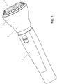
- FIG. 1 a schematic representation of a massage device
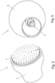
- Fig. 2 a first view of a massage head
- Fig. 3 a second view of a massage head
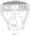
- Fig. 4 a section through a first example of a massage head
- Fig. 5 another view of the first example of the massage head
- Fig. 6 another view of the first example
- Fig. 7 a view of an embodiment of the massage head according to the invention.
- Fig. 1 is a massage device comprising a massage head 1 and a handle element 2 shown in the connected state.
- the massage head 1 has a massage element 3 with a massage surface and a housing 4.
- the invisible drive element in the grip element is connected to the coupling element in the massage head 2, which is also invisible.
- the massage element 1 is shown without the handle element 2. How out Fig. 2 As can be seen, the massage element 3 has a large number of knobs on the massage surface in order to support the massage effect.
- connecting means for drivingly connecting the massage head 1 to the grip element 2 can be seen, in particular an engagement part of the coupling 5 for connection to a drive element arranged in the grip element.
- the clutch 5 is designed in the form shown in order to be set in rotation by the drive element.
- Fig. 4 is a section through a massage head 1 according to a first example.
- the clutch 5 comprises a turntable 6 and is arranged in such a way that the rotational movement provided by the drive element is transmitted to the turntable 6.
- the rotary movement is indicated schematically by arrow 14.
- the turntable 6 comprises several elevations (see Fig. 5 ) which cooperate with massage members 7 arranged above the turntable 6 in order to translate the massage members 7 translationally parallel to the axis of rotation of the turntable 6 between a first and a second position along the arrows 15.
- the massage members 7 thus do not rotate with the turntable 6.
- the massage elements 7 interact with the massage element 3 in such a way that the massage element 3, in particular the massage surface, is deflected locally in the region of the respective massage element 7.
- This provides a pulsating massage surface during operation, which provides a good massage effect for the skin.
- three rows of massage elements 7 are provided concentrically around the axis of rotation of the turntable.
- Each The row comprises a plurality, in particular four, massage members 7 designed as ring segments.
- the turntable 6 has elevations 8, 9, 10, each of which has a leading and a trailing ramp 11 on the sides and an essentially flat central section 12.
- the elevations 8, 9, 10 are each offset by 180 ° in the circumferential direction of the turntable, that is to say they are diametrically opposite one another.
- the elevations 8 are arranged along a first circular line at a first radial distance from the axis of rotation of the turntable 6, the elevations 9 are arranged along a second circular line which is concentric about the first circular line, the elevations 9 each increasing by 90 ° the elevations 8 are arranged offset in the circumferential direction.
- the elevations 10 are arranged on a third circular line which extends concentrically around the first and second circular lines, the elevations 10 being at the same height as the elevations 8 in the circumferential direction of the turntable 6.
- the elevations 8, 9, 10 each interact with the massage members 7, which are arranged at the same distance from the axis of rotation of the turntable 6. This arrangement of the elevations 8, 9, 10 alternately brings a massage member 7 of the first and third rows and then a massage member 7 of the second row into the second position, in which the massage surface is deflected.
- the massage members 7 are shown.
- the massage members 7 are arranged in a circle along three concentric circular lines, four massage members 7 each lying on a circular line.
- the massage elements 7 With the help of arranged below the massage elements 7, the rotating plate 6, the massage elements 7 are moved alternately in translation between a first and a second position in order to cooperate with the massage element, not shown.
- Fig. 7 An embodiment of the massage head 1 is shown.
- the massage members 7 are designed as toothed wheels and can not only be moved translationally with the help of the turntable 6 between a first and a second position, but also rotate in order to provide an additional massage effect.
- an internally toothed ring gear 13 is provided which can be driven together with the turntable 6.
- the massage members 7 are arranged along three concentric circular lines about the axis of rotation of the turntable 6 or the ring gear 13 and are interlocked with one another, so that the rotational movement from the ring gear 13 is first transmitted to the outermost massage members 7 and from there to the other massage members 7.
- the massage members 7 are guided and mounted in such a way that they do not rotate with the rotary movement 14 of the turntable 6.
- the massage members 7 each have an eccentrically arranged extension 16 which interacts with the massage surface of the massage element 3, not shown.
- the translational movement of the massage members 7 parallel to the axis of rotation of the turntable 6 or the ring gear 13 is achieved by elevations 8, 9, 10, as in the in the Fig. 4 and 5 shown execution.
Landscapes
- Health & Medical Sciences (AREA)
- Epidemiology (AREA)
- Pain & Pain Management (AREA)
- Physical Education & Sports Medicine (AREA)
- Rehabilitation Therapy (AREA)
- Life Sciences & Earth Sciences (AREA)
- Animal Behavior & Ethology (AREA)
- General Health & Medical Sciences (AREA)
- Public Health (AREA)
- Veterinary Medicine (AREA)
- Dermatology (AREA)
- Massaging Devices (AREA)
Description
- Die Erfindung betrifft einen Massagekopf, umfassend ein Gehäuse, ein eine Massageoberfläche aufweisendes flexibles Massageelement sowie ein Kupplungselement, welches mit einem Antriebselement antriebsmäßig verbindbar ist gemäß dem Oberbegriff von Anspruch 1.
- Die Erfindung betrifft weiters ein Massagegerät, umfassend einen erfindungsgemäßen Massagekopf sowie ein mit dem Massagekopf verbundenes Griffelement, welches ein mit dem Kupplungselement antriebsmäßig verbundenes Antriebselement aufweist.
-
US 5 685 827 A zeigt und beschreibt einen Massagekopf gemäß dem Oberbegriff von Anspruch 1. - Massageköpfe der eingangs genannten Art werden insbesondere zur Massage von Körperteilen verwendet, indem diese eine mechanische Beaufschlagung von Haut, Bindegewebe und Muskulatur verursachen. Die Massageoberfläche wird in Kontakt mit der Haut gebracht und so bewegt, dass die Massageoberfläche mechanisch auf die Haut, das Bindegewebe und die darunter liegende Muskulatur einwirkt. Die mechanische Einwirkung kann bspw. durch Rotation oder axiale Bewegungen erfolgen. Durch solche Massagen wird das Wohlbefinden der Person verbessert und die Muskelrelaxation gefördert.
- Massageköpfe werden üblicherweise mithilfe eines in einem Griff angeordneten Elektromotors angetrieben. Die benötigte Energie wird von eingebauten Batterien oder über ein elektrisches Kabel vom Stromnetz bereitgestellt. Solche Massagegeräte sind transportabel und können zur Selbstmassage genutzt werden. Massageköpfe sind meistens fest mit einem Griff und mit einer Antriebseinheit verbunden. In manchen Fällen sind der Massagekopf und der Griff auch lösbar verbunden, bspw. um unterschiedliche Aufsätze für einen Griff nutzen zu können.
- Herkömmliche Massagegeräte weisen ein Massageglied auf, das axial verschoben werden kann und dadurch Druck auf die Haut ausübt. Dies hat den Nachteil, dass die Massage punktuell beschränkt ist und das Massagegerät daher laufend über die Haut bewegt werden muss, um eine möglichst gleichmäßige Massagewirkung auf der Haut zu erzielen.
- Es ist daher eine Aufgabe der Erfindung, einen Massagekopf der eingangs genannten Art dahingehend zu verbessern, dass die Massagewirkung verbessert wird. Insbesondere soll die Gleichmäßigkeit der Massage im Bereich der Massageoberfläche erhöht werden.
- Zur Lösung dieser Aufgabe ist erfindungsgemäß eine Mehrzahl von Massagegliedern vorgesehen, die in zumindest einer Richtung von einer ersten in eine zweite Position bewegbar angeordnet sind und in der zweiten Position mit dem Massageelement zur lokalen Auslenkung der Massageoberfläche zusammenwirken, und dass das Kupplungselement im angetriebenen Zustand derart mit der Mehrzahl von Massagegliedern zusammenwirkt, dass die Massageglieder zeitlich versetzt zueinander von der ersten in die zweite Position bewegt werden. Es ist also, im Betrieb, eine gemeinsame Massageoberfläche zwischen den zumindest zwei Massagegliedern und der Haut angeordnet. Durch diese Anordnung ist es möglich, die Massageglieder über einen großen Teil oder die gesamte Erstreckung des Massageelements zu verteilen, sodass über die Massageoberfläche eine gleichmäßige Massagewirkung erzielt wird.
- Die Geschwindigkeit der Bewegung zwischen der ersten und der zweiten Position kann bevorzugt verändert werden, um den Massagekopf besser an die Bedürfnisse des Benutzers anpassen zu können. Weiters kann bevorzugt die Lage der ersten und/oder zweiten Position verändert werden, um den Druck der Massageglieder zu variieren.
- Erfindungsgemäß ist vorgesehen, dass die Massageglieder zur Hin- und Herbewegung zwischen der ersten und der zweiten Position translatorisch geführt sind. Die Massageglieder üben hierbei einen Druck auf die Massageoberfläche aus, der bevorzugt im Wesentlichen senkrecht zur Massageoberfläche und zur Haut ist. Dadurch wird eine pulsierende Massageoberfläche bereitgestellt und eine Klopfmassage der Haut erzielt.
- Weiters ist bevorzugt vorgesehen, dass das Kupplungselement einen rotierend antreibbaren Drehteller mit Erhebungen, insbesondere Rampen, umfasst, die beim Auflaufen auf die Massageglieder zur Verlagerung derselben in die zweite Position mit diesen zusammenwirken. Dieser Aufbau stellt eine einfache und effiziente Lösung dar, um die Bewegung der Massageglieder zu bewirken. Die durch einen Motor, insbesondere Elektromotor bereitgestellte Rotationsbewegung kann direkt zum Antrieb des Drehtellers genutzt werden. Die Massageglieder werden durch die Erhebungen von der ersten Position in die zweite Position und anschließend wieder in die erste Position geführt. Die ebene Fläche des Drehtellers entspricht der ersten Position und die Erhebungen entsprechen der zweiten Position. Hierbei sind bevorzugt Rückstellelemente vorgesehen, um das Führen von der zweiten Position in die erste Position zu unterstützen. Bevorzugt wird das die Massageoberfläche aufweisende flexible Massageelement als Rückstellelement genutzt. Alternativ können zusätzliche Rückstellelemente verwendet werden, bspw. Federelemente. Die Erhebungen weisen bevorzugt eine, besonders bevorzugt zwei Rampen auf, die derart angeordnet sind, dass die Massageglieder während der Rotation des Drehtellers über die erste Rampe auf die Erhebung geführt werden und über die zweite Rampe von der Erhebung zurück auf den Drehteller geführt werden. Die Erhebungen haben hierbei bevorzugt in der Draufsicht die Form eines Kreissektors.
- Um die Massageglieder an ihrer Position zu halten, sind bevorzugt Führungselemente vorgesehen. Diese können bspw. mit dem Massageelement verbunden bzw. einstückig mit dem Massageelement ausgebildet sein. Alternativ oder zusätzlich können auch am Gehäuse angeordnete Führungselemente vorgesehen sein, bspw. eine oder mehrere unterhalb des Massageelements angeordnete Platte mit Ausnehmungen für die Massageglieder. Bei einer Anordnung mit einem Drehteller ist diese Platte daher zwischen dem Massageelement und dem Drehteller angeordnet.
- Um eine besonders gleichmäßige Massage bewirken zu können, ist bevorzugt vorgesehen, dass die Erhebungen in Umfangsrichtung des Drehtellers verteilt angeordnet sind, insbesondere in einem Abstand von 90° oder 180°. Dadurch wird sichergestellt, dass die Massageglieder sich abwechselnd in der zweiten Position befinden bzw. in diese bewegt werden.
- Um die Massagewirkung zu verfeinern, ist bevorzugt vorgesehen, dass die Erhebungen in voneinander verschiedenem radialen Abstand von der Rotationsachse des Drehtellers angeordnet sind. Dadurch können zwei oder mehr Reihen von Massagegliedern bewegt werden.
- Hierbei ist besonders bevorzugt vorgesehen, dass in einem ersten radialen Abstand von der Rotationsachse des Drehtellers angeordnete Erhebungen zu in einem zweiten radialen Abstand von der Rotationsachse des Drehtellers angeordneten Erhebungen im Umfangsrichtung versetzt angeordnet sind. Diese Ausführung ermöglicht es, dass in einem ersten radialen Abstand von der Rotationsachse angeordnete Massageglieder abwechselnd zu in einem zweiten radialen Abstand von der Rotationsachse angeordneten Massagegliedern bewegt werden können.
- Bevorzugt ist vorgesehen, dass zumindest zwei Massageglieder entlang einer ersten kreisförmigen Linie angeordnet sind. Die zumindest zwei Massageglieder sind hierbei so angeordnet, dass sie abwechselnd in die zweite Position bewegt werden. Diese Anordnung ist insbesondere bevorzugt, wenn ein Drehteller mit Erhebungen zur Bewegung der Massageglieder vorgesehen ist. Hierbei laufen die Massageglieder abwechselnd auf die Erhebungen auf und werden somit abwechselnd in die zweite Position gebracht.
- Besonders bevorzugt ist hierbei vorgesehen, dass zumindest zwei weitere Massageglieder entlang einer zweiten kreisförmigen Linie angeordnet sind, die um die erste kreisförmige Linie konzentrisch verläuft. Hierbei können die einzelnen Massageglieder regelmäßig angeordnet sein, also einen im Wesentlichen gleichen Abstand in Umfangsrichtung zwischen den einzelnen Massagegliedern aufweisen. Dadurch wird eine angenehme, gleichmäßige Bewegung der Massageoberfläche erzielt.
- Weiters ist bevorzugt vorgesehen, dass die Massageglieder in einer zur Rotationsachse des Drehtellers parallelen Richtung translatorisch zwischen der ersten und der zweiten Position geführt sind. Dadurch kann die durch die Erhebungen bereitgestellte Bewegung vollständig ausgenutzt werden und eine einfache Konstruktion der Vorrichtung wird ermöglicht.
- Erfindungsgemäß ist vorgesehen, dass das Kupplungselement einen Rotationsantrieb für den rotierenden Antrieb zumindest eines der Massageglieder aufweist oder ausbildet. Diese Rotation kann die Bewegung zwischen der ersten und der zweiten Position bewirken oder eine zusätzliche Bewegungskomponente der Massageglieder darstellen.
- Erfindungsgemäß ist vorgesehen, dass die Massageglieder zur Hin- und Herbewegung zwischen der ersten und der zweiten Position translatorisch jeweils entlang einer Rotationsachse geführt sind und dass wenigstens eines der Massageglieder zusätzlich um die Rotationsachse rotierend gelagert ist. Hierbei werden also gleichzeitig eine translatorische und eine rotatorische Bewegung bereitgestellt, sodass die Massagewirkung erhöht wird.
- Ein einfacher und effizienter Aufbau sieht hierbei vor, dass das zumindest eine Massageglied als Zahnrad ausgebildet ist, das bevorzugt so angeordnet ist, dass es von einem Zahnrad des Kupplungselements angetrieben werden kann.
- Weiters ist bevorzugt vorgesehen, dass das als Drehteller ausgebildete Kupplungselement einen innen verzahnten Zahnkranz aufweist, der mit dem wenigstens einen als Zahnrad ausgebildeten Massageglied kämmt. Die Zahnräder sind hierbei in Richtung senkrecht zur Rotationsachse fest angeordnet, d.h. um eine starr angeordnete Rotationsachse rotierbar gelagert und können ausschließlich rotiert bzw. translatorisch entlang der
- Rotationsachse bewegt werden. Die Rotationsachse bildet die translatorische Führung der
- Massageglieder aus. Der Zahnkranz ist bevorzugt mit dem Drehteller gekoppelt, sodass er mit der gleichen Geschwindigkeit wie der Drehteller rotiert. Dadurch wird der Antrieb des Kupplungselements einfach gehalten. Alternativ kann der Zahnkranz vom Drehteller entkoppelt sein und mit einer anderen Geschwindigkeit und/oder in die Gegenrichtung rotieren.
- Eine weitere bevorzugte Ausführung sieht vor, dass das wenigstens eine mit dem Zahnkranz des Drehtellers verzahnte Massageglied mit einem weiteren als Zahnrad ausgebildeten, radial weiter innen angeordneten Massageglied verzahnt ist. Dadurch wird die Rotationsbewegung vom Zahnkranz des Drehtellers auf ein erstes Zahnrad übertragen und von diesem auf ein zweites Zahnrad. Bevorzugt ist das zweite Zahnrad mit einem dritten, als Massageglied ausgebildeten, radial weiter innen angeordneten Zahnrad verzahnt, um die vom ersten Zahnrad übertragene Rotation auch auf das dritte Zahnrad zu übertragen. Diese Übertragung der Rotationsbewegung von einem Zahnrad auf das nächste erlaubt eine konstruktiv einfache Ausführung, weil lediglich ein einziger Zahnkranz zur Übertragung auf eine Vielzahl von als Zahnräder ausgebildete Massageglieder nötig ist, wobei die einzelnen Zahnräder nicht alle direkt mit dem Zahnkranz verzahnt sein müssen. Weiters wird dadurch auf einfache Art sichergestellt, dass die Zahnräder mit der gleichen Geschwindigkeit rotieren, wodurch die Massagebewegung gleichmäßiger und damit angenehmer wird.
- Um die Rotationsbewegung auf das Massageelement zu übertragen, ist bevorzugt vorgesehen, dass das wenigstens eine rotierend gelagerte, bevorzugt als Zahnrad ausgebildete Massageglied, und ggf. das weitere als Zahnrad ausgebildete Massageglied einen exzentrisch angeordneten Fortsatz aufweist, der mit dem Massageelement zur lokalen Auslenkung der Massageoberfläche zusammenwirkt. Dadurch wird eine Rotationsbewegung über das Massageelement auf die Haut des Benutzers übertragen. Der Fortsatz kann bspw. zylindrisch, quaderförmig oder kugelförmig ausgebildet sein.
- Weiters ist bevorzugt vorgesehen, dass zumindest eines der Massageglieder die Form eines Ringsegments aufweist. Dadurch kann insbesondere der durch eine kreisförmige Anordnung der Massageglieder zur Verfügung stehende Raum bestmöglich ausgefüllt werden, sodass eine gleichmäßigere Massagewirkung erzielt wird. Dies gilt insbesondere dann, wenn zwei oder mehr Reihen von Massagegliedern konzentrisch angeordnet sind.
- Alternativ kann vorgesehen sein, dass zumindest eines der Massageglieder die Form eines Segmentes eines Ovals aufweist.
- Um die Massagewirkung des Massageelements zu erhöhen, ist bevorzugt vorgesehen, dass die Massageoberfläche Erhebungen, insbesondere Noppen aufweist. Die Erhebungen sind bevorzugt abgerundet ausgebildet, um auf der Haut des Benutzers als angenehm empfunden zu werden.
- Das Massageelement besteht bevorzugt im Wesentlichen aus einem Silikon. Silikon ist ein gut geeignetes Material, welches einerseits gut hautverträglich ist und andererseits die für das Massageelement nötige Flexibilität aufweist.
- Weiters ist erfindungsgemäß ein Massagegerät vorgesehen, umfassend einen erfindungsgemäßen Massagekopf sowie ein mit dem Massagekopf verbundenes Griffelement, welches ein mit dem Kupplungselement antriebsmäßig verbundenes Antriebselement aufweist. Der Massagekopf kann hierbei fest mit dem Griffelement verbunden sein und bspw. ein gemeinsames, insbesondere einstückiges Gehäuse aufweisen. Alternativ ist bevorzugt vorgesehen, dass der Massagekopf mit dem Griffelement lösbar verbunden ist, wobei das Kupplungselement im verbundenen Zustand mit dem Antriebselement antriebsmäßig verbunden ist und durch dieses antreibbar ist. Eine solche Ausbildung hat den Vorteil, dass das Griffelement zusätzlich genutzt werden kann, um andere Aufsätze, bspw. Schneidaufsätze zum Haareschneiden oder Rasieren, anzutreiben. Hierbei wird also lediglich ein Griffelement für mehrere Aufsätze, darunter ein Massagekopf, genutzt, sodass die Anzahl der für die Körperpflege erforderlichen Geräte reduziert werden kann.
- Die Erfindung wird nachfolgend anhand eines in der Zeichnung schematisch dargestellten Ausführungsbeispiels näher erläutert, wobei nur die
Fig. 7 eine Ausführungsform zeigt, die von den Ansprüchen abgedeckt ist. - Es zeigt
Fig. 1 eine schematische Darstellung eines Massagegeräts,Fig. 2 eine erste Ansicht eines Massagekopfes,Fig. 3 eine zweite Ansicht eines Massagekopfes,Fig. 4 einen Schnitt durch ein erstes Beispiel eines Massagekopfes,Fig. 5 eine weitere Ansicht des ersten Beispiels des Massagekopfes,Fig. 6 eine weitere Ansicht des ersten Beispiels undFig. 7 eine Ansicht einer erfindungsgemäßen Ausführungsform des Massagekopfes. - In
Fig. 1 ist ein Massagegerät, umfassend einen Massagekopf 1 und ein Griffelement 2 im miteinander verbundenen Zustand dargestellt. Der Massagekopf 1 weist ein Massageelement 3 mit einer Massageoberfläche sowie ein Gehäuse 4 auf. Im dargestellten, verbundenen Zustand ist das nicht sichtbare Antriebselement im Griffelement mit dem ebenfalls nicht sichtbaren Kupplungselement im Massagekopf 2 antriebsmäßig verbunden. - In den
Fig. 2 und 3 ist das Massageelement 1 ohne das Griffelement 2 dargestellt. Wie ausFig. 2 ersichtlich, weist das Massageelement 3 an der Massageoberfläche eine Vielzahl von Noppen auf, um die Massagewirkung zu unterstützen. InFig. 3 sind Verbindungsmittel zum antriebsmäßigen Verbinden des Massagekopfes 1 mit dem Griffelement 2 ersichtlich, wobei insbesondere ein Eingriffsteil der Kupplung 5 zur Verbindung mit einem im Griffelement angeordneten Antriebselement ersichtlich ist. Die Kupplung 5 ist in der dargestellten Form ausgebildet, um durch das Antriebselement in Rotation versetzt zu werden. - In
Fig. 4 ist ein Schnitt durch einen Massagekopf 1 gemäß eines ersten Beispiels dargestellt. Die Kupplung 5 umfasst einen Drehteller 6 und ist so angeordnet, dass die vom Antriebselement bereitgestellte Rotationsbewegung auf den Drehteller 6 übertragen wird. Die Drehbewegung ist schematisch durch den Pfeil 14 bezeichnet. Der Drehteller 6 umfasst mehrere Erhebungen (sieheFig. 5 ), die mit oberhalb des Drehtellers 6 angeordneten Massagegliedern 7 zusammenwirken, um die Massageglieder 7 translatorisch parallel zur Rotationsachse des Drehtellers 6 zwischen einer ersten und einer zweiten Position entlang der Pfeile 15 zu verschieben. Die Massageglieder 7 rotieren somit nicht mit dem Drehteller 6 mit. In der zweiten Position wirken die Massageglieder 7 so mit dem Massageelement 3 zusammen, dass das Massageelement 3, insbesondere die Massageoberfläche lokal im Bereich des jeweiligen Massageglieds 7 ausgelenkt wird. Dadurch wird im Betrieb eine pulsierende Massageoberfläche bereitgestellt, die eine gute Massagewirkung für die Haut zur Verfügung stellt. In der dargestellten Ausbildung sind drei Reihen konzentrisch um die Rotationsachse des Drehtellers angeordnete Massageglieder 7 vorgesehen. Jede Reihe umfasst eine Mehrzahl, insbesondere vier, als Ringsegmente ausgebildete Massagegliedern 7. - In
Fig. 5 sind die Massageglieder 7 sowie das Massageelement 3 nicht dargestellt. Der Drehteller 6 weist Erhebungen 8,9,10 auf, die jeweils eine vorauseilende und eine nacheilende Rampe 11 an den Seiten sowie einen im Wesentlichen ebenen Mittelabschnitt 12 aufweisen. Die Erhebungen 8,9,10 sind jeweils in Umfangsrichtung des Drehtellers um 180° versetzt angeordnet, liegen also einander jeweils diametral gegenüber. Die Erhebungen 8 sind entlang einer ersten kreisförmigen Linie in einem ersten radialen Abstand von der Rotationsachse des Drehtellers 6 angeordnet, die Erhebungen 9 sind entlang einer zweiten, um die erste kreisförmige Linie konzentrisch verlaufenden kreisförmigen Linie angeordnet, wobei die Erhebungen 9 jeweils um 90° zu den Erhebungen 8 in Umfangsrichtung versetzt angeordnet sind. Die Erhebungen 10 sind auf einer dritten, um die erste und zweite kreisförmige Linie konzentrisch verlaufenden kreisförmigen Linie angeordnet, wobei die Erhebungen 10 in Umfangsrichtung des Drehtellers 6 auf gleicher Höhe wie die Erhebungen 8 liegen. Die Erhebungen 8, 9, 10 wirken jeweils mit den Massagegliedern 7 zusammen, die im gleichen Abstand von der Rotationsachse des Drehtellers 6 angeordnet sind. Durch diese Anordnung der Erhebungen 8,9,10 wird abwechselnd zuerst ein Massageglied 7 der ersten und dritten Reihe und anschließend ein Massageglied 7 der zweiten Reihe in die zweite Position gebracht, in der die Massageoberfläche ausgelenkt wird. - In
Fig. 6 sind die Massageglieder 7 dargestellt. In diesem Beispiel sind die Massageglieder 7 kreisförmig entlang dreier konzentrischer Kreislinien angeordnet, wobei jeweils vier Massageglieder 7 auf einer Kreislinie liegen. Mithilfe der unterhalb der Massageglieder 7 angeordneten Drehplatte 6 werden die Massageglieder 7 abwechselnd translatorisch zwischen einer ersten und einer zweiten Position bewegt, um mit dem nicht dargestellten Massageelement zusammenzuwirken. - In
Fig. 7 ist eine erfindungsgemäße Ausführungsform des Massagekopfes 1 dargestellt. Im Unterschied zur Ausführung gemäßFig. 4 sind die Massageglieder 7 als Zahnräder ausgebildet und können nicht nur translatorisch mithilfe des Drehtellers 6 zwischen einer ersten und einer zweiten Position bewegt werden, sondern zusätzlich rotieren, um einen zusätzlichen Massageeffekt bereitzustellen. Hierzu ist ein innen verzahnter Zahnkranz 13 vorgesehen, der zusammen mit dem Drehteller 6 antreibbar ist. Die Massageglieder 7 sind entlang dreier konzentrischer Kreislinien um die Rotationsachse des Drehtellers 6 bzw. des Zahnkranzes 13 angeordnet und miteinander verzahnt, sodass die Rotationsbewegung vom Zahnkranz 13 zuerst auf die äußersten Massageglieder 7 übertragen wird und von diesen auf die anderen Massageglieder 7. Die Massageglieder 7 sind so geführt und gelagert, dass sie sich nicht mit der Drehbewegung 14 des Drehtellers 6 mitdrehen. Die Massageglieder 7 weisen jeweils einen exzentrisch angeordneten Fortsatz 16 auf, der mit der nicht dargestellten Massageoberfläche des Massageelements 3 zusammenwirkt. Die translatorische Bewegung der Massageglieder 7 parallel zur Rotationsachse des Drehtellers 6 bzw. des Zahnkranzes 13 wird durch Erhebungen 8, 9, 10 erzielt, wie auch bei der in denFig. 4 und5 dargestellten Ausführung.
Claims (16)
- Massagekopf, umfassend ein Gehäuse, ein eine Massageoberfläche aufweisendes flexibles Massageelement sowie ein Kupplungselement, welches mit einem Antriebselement antriebsmäßig verbindbar ist, wobei eine Mehrzahl von Massagegliedern (7) vorgesehen ist, die in zumindest einer Richtung von einer ersten in eine zweite Position bewegbar angeordnet sind und in der zweiten Position mit dem Massageelement (3) zur lokalen Auslenkung der Massageoberfläche zusammenwirken, und wobei das Kupplungselement (5) im angetriebenen Zustand derart mit der Mehrzahl von Massagegliedern (7) zusammenwirkt, dass die Massageglieder (7) zeitlich versetzt zueinander von der ersten in die zweite Position bewegt werden, dadurch gekennzeichnet, dass die Massageglieder (7) zur Hin- und Herbewegung zwischen der ersten und der zweiten Position translatorisch jeweils entlang einer Rotationsachse geführt sind und dass zumindest ein Massageglied (7) zusätzlich um die Rotationsachse rotierend gelagert ist, wobei die Rotationsachse die translatorische Führung des zumindest einen Massageglieds bildet und das Kupplungselement (5) einen Rotationsantrieb für den rotierenden Antrieb des zumindest einen Massageglieds (7) um die Rotationsachse aufweist oder ausbildet.
- Massagekopf nach Anspruch 1, dadurch gekennzeichnet, dass das Kupplungselement (5) einen rotierend antreibbaren Drehteller (6) mit Erhebungen (8,9,10), insbesondere Rampen, umfasst, die beim Auflaufen auf die Massageglieder (7) zur Verlagerung derselben in die zweite Position mit diesen zusammenwirken.
- Massagekopf nach Anspruch 2, dadurch gekennzeichnet, dass die Erhebungen (8,9,10) in Umfangsrichtung des Drehtellers (6) verteilt angeordnet sind, insbesondere in einem Abstand von 90° oder 180°.
- Massagekopf nach Anspruch 2 oder 3, dadurch gekennzeichnet, dass die Erhebungen (8,9,10) in voneinander verschiedenem radialen Abstand von der Rotationsachse des Drehtellers (6) angeordnet sind.
- Massagekopf nach einem der Ansprüche 2 bis 4, dadurch gekennzeichnet, dass in einem ersten radialen Abstand von der Rotationsachse des Drehtellers (6) angeordnete Erhebungen (8) zu in einem zweiten radialen Abstand von der Rotationsachse des Drehtellers (6) angeordneten Erhebungen (9) im Umfangsrichtung versetzt angeordnet sind.
- Massagekopf nach einem der Ansprüche 1 bis 5, dadurch gekennzeichnet, dass zumindest zwei Massageglieder (7) entlang einer ersten kreisförmigen Linie angeordnet sind.
- Massagekopf nach Anspruch 6, dadurch gekennzeichnet, dass zumindest zwei weitere Massageglieder (7) entlang einer zweiten kreisförmigen Linie angeordnet sind, die um die erste kreisförmige Linie konzentrisch verläuft.
- Massagekopf nach einem der Ansprüche 2 bis 7, dadurch gekennzeichnet, dass die Massageglieder (7) in einer zur Rotationsachse des Drehtellers (6) parallelen Richtung translatorisch zwischen der ersten und der zweiten Position geführt sind.
- Massagekopf nach einem der Ansprüche 1 bis 8, dadurch gekennzeichnet, dass das zumindest eine Massageglied (7) als Zahnrad ausgebildet ist, das bevorzugt so angeordnet ist, dass es von einem Zahnrad des Kupplungselements (5) angetrieben werden kann.
- Massagekopf nach einem der Ansprüche 1 bis 9, dadurch gekennzeichnet, dass das als Drehteller (6) ausgebildete Kupplungselement (5) einen innen verzahnten Zahnkranz (13) aufweist, der mit dem wenigstens einen als Zahnrad ausgebildeten Massageglied (7) kämmt.
- Massagekopf nach Anspruch 10, dadurch gekennzeichnet, dass das wenigstens eine mit dem Zahnkranz (13) des Drehtellers (6) verzahnte Massageglied (7) mit einem weiteren als Zahnrad ausgebildeten, radial weiter innen angeordneten Massageglied (7) verzahnt ist.
- Massagekopf nach einem der Ansprüche 1 bis 11, dadurch gekennzeichnet, dass das wenigstens eine rotierend gelagerte, bevorzugt als Zahnrad ausgebildete Massageglied (7), und ggf. das weitere als Zahnrad ausgebildete Massageglied (7) einen exzentrisch angeordneten Fortsatz (16) aufweist, der mit dem Massageelement (3) zur lokalen Auslenkung der Massageoberfläche zusammenwirkt.
- Massagekopf nach einem der Ansprüche 1 bis 8, dadurch gekennzeichnet, dass zumindest eines der Massageglieder (7) die Form eines Ringsegments aufweist.
- Massagekopf nach einem der Ansprüche 1 bis 13, dadurch gekennzeichnet, dass die Massageoberfläche Erhebungen, insbesondere Noppen aufweist.
- Massagekopf nach einem der Ansprüche 1 bis 14, dadurch gekennzeichnet, dass das Massageelement (3) im Wesentlichen aus einem Silikon besteht.
- Massagegerät, umfassend einen Massagekopf (1) nach einem der Ansprüche 1 bis 15 sowie ein mit dem Massagekopf (1) verbundenes Griffelement (2), welches ein mit dem Kupplungselement (5) antriebsmäßig verbundenes Antriebselement aufweist.
Applications Claiming Priority (2)
| Application Number | Priority Date | Filing Date | Title |
|---|---|---|---|
| ATA477/2016A AT519126B1 (de) | 2016-10-14 | 2016-10-14 | Massagekopf |
| PCT/AT2017/000066 WO2018068069A1 (de) | 2016-10-14 | 2017-09-19 | Massagekopf |
Publications (2)
| Publication Number | Publication Date |
|---|---|
| EP3525745A1 EP3525745A1 (de) | 2019-08-21 |
| EP3525745B1 true EP3525745B1 (de) | 2020-07-22 |
Family
ID=60001623
Family Applications (1)
| Application Number | Title | Priority Date | Filing Date |
|---|---|---|---|
| EP17777767.9A Active EP3525745B1 (de) | 2016-10-14 | 2017-09-19 | Massagekopf |
Country Status (4)
| Country | Link |
|---|---|
| EP (1) | EP3525745B1 (de) |
| CN (1) | CN109922773A (de) |
| AT (1) | AT519126B1 (de) |
| WO (1) | WO2018068069A1 (de) |
Families Citing this family (2)
| Publication number | Priority date | Publication date | Assignee | Title |
|---|---|---|---|---|
| USD959150S1 (en) | 2020-03-04 | 2022-08-02 | Church & Dwight Co., Inc. | Combination skincare cleansing brush and cradle |
| CN112618326A (zh) * | 2021-01-07 | 2021-04-09 | 焦玉磊 | 一种医用脾胃病经络敲击理疗装置 |
Family Cites Families (17)
| Publication number | Priority date | Publication date | Assignee | Title |
|---|---|---|---|---|
| US1387687A (en) * | 1913-04-02 | 1921-08-16 | Chaussin Paul Louis Hippolyte | Massaging apparatus |
| US1579679A (en) * | 1924-10-10 | 1926-04-06 | Wahrt William | Massage device |
| JPS5474187U (de) * | 1977-11-04 | 1979-05-26 | ||
| LU82610A1 (fr) * | 1980-07-10 | 1982-02-17 | Faco Sa | Appareil de massage electrique |
| WO1994013244A1 (fr) * | 1992-12-14 | 1994-06-23 | Daito Electric Machine Industry Company Limited | Machine de massage du type a rouleaux |
| JPH09122196A (ja) * | 1995-11-01 | 1997-05-13 | Shibaura Eng Works Co Ltd | 按摩機 |
| US5803916A (en) * | 1996-03-19 | 1998-09-08 | Vital-Tech Ltd. | Body and joints massage device |
| WO1997049372A1 (en) * | 1996-06-24 | 1997-12-31 | Step To Health, L.L.C. | Powered foot massager and method |
| CN1314383C (zh) * | 2004-04-30 | 2007-05-09 | 深圳大学 | 足部仿生按摩器 |
| ITVI20060065A1 (it) * | 2006-03-13 | 2007-09-14 | Armonie Del Benessere | Apparecchio per massaggi localizzati ad uso estetico e di benessere |
| CN102245935B (zh) * | 2008-10-12 | 2015-04-08 | 克里斯多佛·C·萨彭菲尔德 | 旋转单元、旋转机构以及相关应用 |
| CN201316391Y (zh) * | 2008-12-03 | 2009-09-30 | 蔡明卫 | 按摩器 |
| CN201734918U (zh) * | 2010-07-15 | 2011-02-09 | 浙江金恒数控科技股份有限公司 | 滚柱控制装置 |
| CN202568769U (zh) * | 2012-04-28 | 2012-12-05 | 陈绍伦 | 一种自转式按摩机构 |
| FR3012034B1 (fr) * | 2013-10-17 | 2018-09-28 | Seb S.A. | Appareil de massage avec au moins une tete de massage a rotation excentree |
| CN205073256U (zh) * | 2015-11-03 | 2016-03-09 | 李锦祥 | 一种指压式按摩装置 |
| CN205598180U (zh) * | 2016-02-19 | 2016-09-28 | 蔡明卫 | 健胸按摩装置 |
-
2016
- 2016-10-14 AT ATA477/2016A patent/AT519126B1/de active
-
2017
- 2017-09-19 WO PCT/AT2017/000066 patent/WO2018068069A1/de not_active Ceased
- 2017-09-19 EP EP17777767.9A patent/EP3525745B1/de active Active
- 2017-09-19 CN CN201780063495.4A patent/CN109922773A/zh active Pending
Non-Patent Citations (1)
| Title |
|---|
| None * |
Also Published As
| Publication number | Publication date |
|---|---|
| WO2018068069A1 (de) | 2018-04-19 |
| AT519126B1 (de) | 2018-04-15 |
| AT519126A4 (de) | 2018-04-15 |
| EP3525745A1 (de) | 2019-08-21 |
| CN109922773A (zh) | 2019-06-21 |
Similar Documents
| Publication | Publication Date | Title |
|---|---|---|
| DE3236791C2 (de) | ||
| EP0269702B1 (de) | Elektrisches gerät für die mundpflege | |
| DE2621637C2 (de) | Applikator für kosmetische Produkte, besonders Wimperntusche | |
| DE3936632C2 (de) | ||
| DE69524193T2 (de) | Massagegerät | |
| EP2191805A1 (de) | Massagegerät für das männliche Geschlechtsteil | |
| WO1998047443A1 (de) | Elektrisch betriebenes zahnreinigungsgerät | |
| EP1720503A1 (de) | Massagegerät | |
| DE102005003409A1 (de) | Rotierender Massagestab | |
| AT519126B1 (de) | Massagekopf | |
| DE69101278T2 (de) | Enthaarungsgerät. | |
| DE2857650C2 (de) | Zahnbürste | |
| DE202014006715U1 (de) | Massage-Vorrichtung | |
| DE4318976A1 (de) | Elektromechanische Zahnbürste | |
| DE202021104542U1 (de) | Massagegerät und Massagemechanismus davon | |
| DE2332675A1 (de) | Steuervorrichtung fuer elektromechanische zeitwerke | |
| EP1959787B1 (de) | Haarentfernungsgerät mit verschiedenen werkzeugaufsätzen | |
| DE202018105072U1 (de) | Handgehaltenes Haarstyling-Gerät | |
| DE1112966B (de) | Zahnbuerste | |
| DE102014012324A1 (de) | Massage-Vorrichtung | |
| AT7332U1 (de) | Epilationsgerät | |
| DE958016C (de) | Vorrichtung zum Abstumpfen und Abrunden der Borstenspitzen von Buersten | |
| DE2914717A1 (de) | Geraet zur koerpermassage | |
| DE3829910C2 (de) | ||
| DE3735436A1 (de) | Elektrische zahnbuerste |
Legal Events
| Date | Code | Title | Description |
|---|---|---|---|
| STAA | Information on the status of an ep patent application or granted ep patent |
Free format text: STATUS: UNKNOWN |
|
| STAA | Information on the status of an ep patent application or granted ep patent |
Free format text: STATUS: THE INTERNATIONAL PUBLICATION HAS BEEN MADE |
|
| PUAI | Public reference made under article 153(3) epc to a published international application that has entered the european phase |
Free format text: ORIGINAL CODE: 0009012 |
|
| STAA | Information on the status of an ep patent application or granted ep patent |
Free format text: STATUS: REQUEST FOR EXAMINATION WAS MADE |
|
| 17P | Request for examination filed |
Effective date: 20190228 |
|
| AK | Designated contracting states |
Kind code of ref document: A1 Designated state(s): AL AT BE BG CH CY CZ DE DK EE ES FI FR GB GR HR HU IE IS IT LI LT LU LV MC MK MT NL NO PL PT RO RS SE SI SK SM TR |
|
| AX | Request for extension of the european patent |
Extension state: BA ME |
|
| DAV | Request for validation of the european patent (deleted) | ||
| DAX | Request for extension of the european patent (deleted) | ||
| GRAP | Despatch of communication of intention to grant a patent |
Free format text: ORIGINAL CODE: EPIDOSNIGR1 |
|
| STAA | Information on the status of an ep patent application or granted ep patent |
Free format text: STATUS: GRANT OF PATENT IS INTENDED |
|
| INTG | Intention to grant announced |
Effective date: 20200303 |
|
| GRAS | Grant fee paid |
Free format text: ORIGINAL CODE: EPIDOSNIGR3 |
|
| GRAA | (expected) grant |
Free format text: ORIGINAL CODE: 0009210 |
|
| STAA | Information on the status of an ep patent application or granted ep patent |
Free format text: STATUS: THE PATENT HAS BEEN GRANTED |
|
| AK | Designated contracting states |
Kind code of ref document: B1 Designated state(s): AL AT BE BG CH CY CZ DE DK EE ES FI FR GB GR HR HU IE IS IT LI LT LU LV MC MK MT NL NO PL PT RO RS SE SI SK SM TR |
|
| REG | Reference to a national code |
Ref country code: GB Ref legal event code: FG4D Free format text: NOT ENGLISH |
|
| REG | Reference to a national code |
Ref country code: CH Ref legal event code: EP |
|
| REG | Reference to a national code |
Ref country code: DE Ref legal event code: R096 Ref document number: 502017006351 Country of ref document: DE |
|
| REG | Reference to a national code |
Ref country code: AT Ref legal event code: REF Ref document number: 1292700 Country of ref document: AT Kind code of ref document: T Effective date: 20200815 |
|
| REG | Reference to a national code |
Ref country code: IE Ref legal event code: FG4D Free format text: LANGUAGE OF EP DOCUMENT: GERMAN |
|
| REG | Reference to a national code |
Ref country code: LT Ref legal event code: MG4D |
|
| PG25 | Lapsed in a contracting state [announced via postgrant information from national office to epo] |
Ref country code: SE Free format text: LAPSE BECAUSE OF FAILURE TO SUBMIT A TRANSLATION OF THE DESCRIPTION OR TO PAY THE FEE WITHIN THE PRESCRIBED TIME-LIMIT Effective date: 20200722 Ref country code: NO Free format text: LAPSE BECAUSE OF FAILURE TO SUBMIT A TRANSLATION OF THE DESCRIPTION OR TO PAY THE FEE WITHIN THE PRESCRIBED TIME-LIMIT Effective date: 20201022 Ref country code: FI Free format text: LAPSE BECAUSE OF FAILURE TO SUBMIT A TRANSLATION OF THE DESCRIPTION OR TO PAY THE FEE WITHIN THE PRESCRIBED TIME-LIMIT Effective date: 20200722 Ref country code: GR Free format text: LAPSE BECAUSE OF FAILURE TO SUBMIT A TRANSLATION OF THE DESCRIPTION OR TO PAY THE FEE WITHIN THE PRESCRIBED TIME-LIMIT Effective date: 20201023 Ref country code: LT Free format text: LAPSE BECAUSE OF FAILURE TO SUBMIT A TRANSLATION OF THE DESCRIPTION OR TO PAY THE FEE WITHIN THE PRESCRIBED TIME-LIMIT Effective date: 20200722 Ref country code: HR Free format text: LAPSE BECAUSE OF FAILURE TO SUBMIT A TRANSLATION OF THE DESCRIPTION OR TO PAY THE FEE WITHIN THE PRESCRIBED TIME-LIMIT Effective date: 20200722 Ref country code: PT Free format text: LAPSE BECAUSE OF FAILURE TO SUBMIT A TRANSLATION OF THE DESCRIPTION OR TO PAY THE FEE WITHIN THE PRESCRIBED TIME-LIMIT Effective date: 20201123 Ref country code: BG Free format text: LAPSE BECAUSE OF FAILURE TO SUBMIT A TRANSLATION OF THE DESCRIPTION OR TO PAY THE FEE WITHIN THE PRESCRIBED TIME-LIMIT Effective date: 20201022 Ref country code: ES Free format text: LAPSE BECAUSE OF FAILURE TO SUBMIT A TRANSLATION OF THE DESCRIPTION OR TO PAY THE FEE WITHIN THE PRESCRIBED TIME-LIMIT Effective date: 20200722 |
|
| PG25 | Lapsed in a contracting state [announced via postgrant information from national office to epo] |
Ref country code: PL Free format text: LAPSE BECAUSE OF FAILURE TO SUBMIT A TRANSLATION OF THE DESCRIPTION OR TO PAY THE FEE WITHIN THE PRESCRIBED TIME-LIMIT Effective date: 20200722 Ref country code: RS Free format text: LAPSE BECAUSE OF FAILURE TO SUBMIT A TRANSLATION OF THE DESCRIPTION OR TO PAY THE FEE WITHIN THE PRESCRIBED TIME-LIMIT Effective date: 20200722 Ref country code: LV Free format text: LAPSE BECAUSE OF FAILURE TO SUBMIT A TRANSLATION OF THE DESCRIPTION OR TO PAY THE FEE WITHIN THE PRESCRIBED TIME-LIMIT Effective date: 20200722 Ref country code: IS Free format text: LAPSE BECAUSE OF FAILURE TO SUBMIT A TRANSLATION OF THE DESCRIPTION OR TO PAY THE FEE WITHIN THE PRESCRIBED TIME-LIMIT Effective date: 20201122 |
|
| PG25 | Lapsed in a contracting state [announced via postgrant information from national office to epo] |
Ref country code: NL Free format text: LAPSE BECAUSE OF FAILURE TO SUBMIT A TRANSLATION OF THE DESCRIPTION OR TO PAY THE FEE WITHIN THE PRESCRIBED TIME-LIMIT Effective date: 20200722 |
|
| REG | Reference to a national code |
Ref country code: DE Ref legal event code: R097 Ref document number: 502017006351 Country of ref document: DE |
|
| PG25 | Lapsed in a contracting state [announced via postgrant information from national office to epo] |
Ref country code: RO Free format text: LAPSE BECAUSE OF FAILURE TO SUBMIT A TRANSLATION OF THE DESCRIPTION OR TO PAY THE FEE WITHIN THE PRESCRIBED TIME-LIMIT Effective date: 20200722 Ref country code: DK Free format text: LAPSE BECAUSE OF FAILURE TO SUBMIT A TRANSLATION OF THE DESCRIPTION OR TO PAY THE FEE WITHIN THE PRESCRIBED TIME-LIMIT Effective date: 20200722 Ref country code: CZ Free format text: LAPSE BECAUSE OF FAILURE TO SUBMIT A TRANSLATION OF THE DESCRIPTION OR TO PAY THE FEE WITHIN THE PRESCRIBED TIME-LIMIT Effective date: 20200722 Ref country code: EE Free format text: LAPSE BECAUSE OF FAILURE TO SUBMIT A TRANSLATION OF THE DESCRIPTION OR TO PAY THE FEE WITHIN THE PRESCRIBED TIME-LIMIT Effective date: 20200722 Ref country code: SM Free format text: LAPSE BECAUSE OF FAILURE TO SUBMIT A TRANSLATION OF THE DESCRIPTION OR TO PAY THE FEE WITHIN THE PRESCRIBED TIME-LIMIT Effective date: 20200722 Ref country code: IT Free format text: LAPSE BECAUSE OF FAILURE TO SUBMIT A TRANSLATION OF THE DESCRIPTION OR TO PAY THE FEE WITHIN THE PRESCRIBED TIME-LIMIT Effective date: 20200722 |
|
| REG | Reference to a national code |
Ref country code: CH Ref legal event code: PL |
|
| PLBE | No opposition filed within time limit |
Free format text: ORIGINAL CODE: 0009261 |
|
| STAA | Information on the status of an ep patent application or granted ep patent |
Free format text: STATUS: NO OPPOSITION FILED WITHIN TIME LIMIT |
|
| PG25 | Lapsed in a contracting state [announced via postgrant information from national office to epo] |
Ref country code: AL Free format text: LAPSE BECAUSE OF FAILURE TO SUBMIT A TRANSLATION OF THE DESCRIPTION OR TO PAY THE FEE WITHIN THE PRESCRIBED TIME-LIMIT Effective date: 20200722 |
|
| REG | Reference to a national code |
Ref country code: BE Ref legal event code: MM Effective date: 20200930 |
|
| 26N | No opposition filed |
Effective date: 20210423 |
|
| PG25 | Lapsed in a contracting state [announced via postgrant information from national office to epo] |
Ref country code: LU Free format text: LAPSE BECAUSE OF NON-PAYMENT OF DUE FEES Effective date: 20200919 Ref country code: SK Free format text: LAPSE BECAUSE OF FAILURE TO SUBMIT A TRANSLATION OF THE DESCRIPTION OR TO PAY THE FEE WITHIN THE PRESCRIBED TIME-LIMIT Effective date: 20200722 |
|
| PG25 | Lapsed in a contracting state [announced via postgrant information from national office to epo] |
Ref country code: FR Free format text: LAPSE BECAUSE OF NON-PAYMENT OF DUE FEES Effective date: 20200922 |
|
| PG25 | Lapsed in a contracting state [announced via postgrant information from national office to epo] |
Ref country code: BE Free format text: LAPSE BECAUSE OF NON-PAYMENT OF DUE FEES Effective date: 20200930 Ref country code: CH Free format text: LAPSE BECAUSE OF NON-PAYMENT OF DUE FEES Effective date: 20200930 Ref country code: SI Free format text: LAPSE BECAUSE OF FAILURE TO SUBMIT A TRANSLATION OF THE DESCRIPTION OR TO PAY THE FEE WITHIN THE PRESCRIBED TIME-LIMIT Effective date: 20200722 Ref country code: IE Free format text: LAPSE BECAUSE OF NON-PAYMENT OF DUE FEES Effective date: 20200919 Ref country code: LI Free format text: LAPSE BECAUSE OF NON-PAYMENT OF DUE FEES Effective date: 20200930 |
|
| REG | Reference to a national code |
Ref country code: NL Ref legal event code: MP Effective date: 20200722 |
|
| GBPC | Gb: european patent ceased through non-payment of renewal fee |
Effective date: 20210919 |
|
| PG25 | Lapsed in a contracting state [announced via postgrant information from national office to epo] |
Ref country code: TR Free format text: LAPSE BECAUSE OF FAILURE TO SUBMIT A TRANSLATION OF THE DESCRIPTION OR TO PAY THE FEE WITHIN THE PRESCRIBED TIME-LIMIT Effective date: 20200722 Ref country code: MT Free format text: LAPSE BECAUSE OF FAILURE TO SUBMIT A TRANSLATION OF THE DESCRIPTION OR TO PAY THE FEE WITHIN THE PRESCRIBED TIME-LIMIT Effective date: 20200722 Ref country code: CY Free format text: LAPSE BECAUSE OF FAILURE TO SUBMIT A TRANSLATION OF THE DESCRIPTION OR TO PAY THE FEE WITHIN THE PRESCRIBED TIME-LIMIT Effective date: 20200722 |
|
| PG25 | Lapsed in a contracting state [announced via postgrant information from national office to epo] |
Ref country code: MK Free format text: LAPSE BECAUSE OF FAILURE TO SUBMIT A TRANSLATION OF THE DESCRIPTION OR TO PAY THE FEE WITHIN THE PRESCRIBED TIME-LIMIT Effective date: 20200722 Ref country code: MC Free format text: LAPSE BECAUSE OF FAILURE TO SUBMIT A TRANSLATION OF THE DESCRIPTION OR TO PAY THE FEE WITHIN THE PRESCRIBED TIME-LIMIT Effective date: 20200722 |
|
| PG25 | Lapsed in a contracting state [announced via postgrant information from national office to epo] |
Ref country code: GB Free format text: LAPSE BECAUSE OF NON-PAYMENT OF DUE FEES Effective date: 20210919 |
|
| REG | Reference to a national code |
Ref country code: AT Ref legal event code: MM01 Ref document number: 1292700 Country of ref document: AT Kind code of ref document: T Effective date: 20220919 |
|
| PG25 | Lapsed in a contracting state [announced via postgrant information from national office to epo] |
Ref country code: AT Free format text: LAPSE BECAUSE OF NON-PAYMENT OF DUE FEES Effective date: 20220919 |
|
| PGFP | Annual fee paid to national office [announced via postgrant information from national office to epo] |
Ref country code: DE Payment date: 20250903 Year of fee payment: 9 |