EP3525538B1 - Downlink information transmission method, apparatus and device - Google Patents
Downlink information transmission method, apparatus and device Download PDFInfo
- Publication number
- EP3525538B1 EP3525538B1 EP17867789.4A EP17867789A EP3525538B1 EP 3525538 B1 EP3525538 B1 EP 3525538B1 EP 17867789 A EP17867789 A EP 17867789A EP 3525538 B1 EP3525538 B1 EP 3525538B1
- Authority
- EP
- European Patent Office
- Prior art keywords
- transport block
- time
- transport
- location
- frequency resource
- Prior art date
- Legal status (The legal status is an assumption and is not a legal conclusion. Google has not performed a legal analysis and makes no representation as to the accuracy of the status listed.)
- Active
Links
- 230000005540 biological transmission Effects 0.000 title claims description 76
- 238000000034 method Methods 0.000 title claims description 62
- 238000012545 processing Methods 0.000 claims description 32
- 238000004590 computer program Methods 0.000 claims description 20
- 238000003860 storage Methods 0.000 claims description 13
- 238000004891 communication Methods 0.000 description 15
- 230000011664 signaling Effects 0.000 description 15
- 238000010586 diagram Methods 0.000 description 14
- 238000013507 mapping Methods 0.000 description 13
- 230000000694 effects Effects 0.000 description 7
- 238000013468 resource allocation Methods 0.000 description 5
- 125000004122 cyclic group Chemical group 0.000 description 4
- 230000001174 ascending effect Effects 0.000 description 3
- 238000011156 evaluation Methods 0.000 description 2
- 238000009776 industrial production Methods 0.000 description 2
- 230000003993 interaction Effects 0.000 description 2
- 230000003287 optical effect Effects 0.000 description 2
- 101000741965 Homo sapiens Inactive tyrosine-protein kinase PRAG1 Proteins 0.000 description 1
- 102100038659 Inactive tyrosine-protein kinase PRAG1 Human genes 0.000 description 1
- 101150069124 RAN1 gene Proteins 0.000 description 1
- 101100355633 Salmo salar ran gene Proteins 0.000 description 1
- 230000006399 behavior Effects 0.000 description 1
- 238000001514 detection method Methods 0.000 description 1
- 238000005516 engineering process Methods 0.000 description 1
- VJYFKVYYMZPMAB-UHFFFAOYSA-N ethoprophos Chemical compound CCCSP(=O)(OCC)SCCC VJYFKVYYMZPMAB-UHFFFAOYSA-N 0.000 description 1
- 239000007787 solid Substances 0.000 description 1
- 238000001228 spectrum Methods 0.000 description 1
Images


Classifications
-
- H—ELECTRICITY
- H04—ELECTRIC COMMUNICATION TECHNIQUE
- H04L—TRANSMISSION OF DIGITAL INFORMATION, e.g. TELEGRAPHIC COMMUNICATION
- H04L1/00—Arrangements for detecting or preventing errors in the information received
- H04L1/0001—Systems modifying transmission characteristics according to link quality, e.g. power backoff
- H04L1/0009—Systems modifying transmission characteristics according to link quality, e.g. power backoff by adapting the channel coding
-
- H—ELECTRICITY
- H04—ELECTRIC COMMUNICATION TECHNIQUE
- H04W—WIRELESS COMMUNICATION NETWORKS
- H04W72/00—Local resource management
- H04W72/20—Control channels or signalling for resource management
- H04W72/23—Control channels or signalling for resource management in the downlink direction of a wireless link, i.e. towards a terminal
-
- H—ELECTRICITY
- H04—ELECTRIC COMMUNICATION TECHNIQUE
- H04L—TRANSMISSION OF DIGITAL INFORMATION, e.g. TELEGRAPHIC COMMUNICATION
- H04L1/00—Arrangements for detecting or preventing errors in the information received
-
- H—ELECTRICITY
- H04—ELECTRIC COMMUNICATION TECHNIQUE
- H04L—TRANSMISSION OF DIGITAL INFORMATION, e.g. TELEGRAPHIC COMMUNICATION
- H04L1/00—Arrangements for detecting or preventing errors in the information received
- H04L1/004—Arrangements for detecting or preventing errors in the information received by using forward error control
- H04L1/0041—Arrangements at the transmitter end
- H04L1/0042—Encoding specially adapted to other signal generation operation, e.g. in order to reduce transmit distortions, jitter, or to improve signal shape
-
- H—ELECTRICITY
- H04—ELECTRIC COMMUNICATION TECHNIQUE
- H04L—TRANSMISSION OF DIGITAL INFORMATION, e.g. TELEGRAPHIC COMMUNICATION
- H04L1/00—Arrangements for detecting or preventing errors in the information received
- H04L1/004—Arrangements for detecting or preventing errors in the information received by using forward error control
- H04L1/0041—Arrangements at the transmitter end
- H04L1/0043—Realisations of complexity reduction techniques, e.g. use of look-up tables
-
- H—ELECTRICITY
- H04—ELECTRIC COMMUNICATION TECHNIQUE
- H04L—TRANSMISSION OF DIGITAL INFORMATION, e.g. TELEGRAPHIC COMMUNICATION
- H04L1/00—Arrangements for detecting or preventing errors in the information received
- H04L1/004—Arrangements for detecting or preventing errors in the information received by using forward error control
- H04L1/0045—Arrangements at the receiver end
- H04L1/0052—Realisations of complexity reduction techniques, e.g. pipelining or use of look-up tables
-
- H—ELECTRICITY
- H04—ELECTRIC COMMUNICATION TECHNIQUE
- H04L—TRANSMISSION OF DIGITAL INFORMATION, e.g. TELEGRAPHIC COMMUNICATION
- H04L1/00—Arrangements for detecting or preventing errors in the information received
- H04L1/0078—Avoidance of errors by organising the transmitted data in a format specifically designed to deal with errors, e.g. location
-
- H—ELECTRICITY
- H04—ELECTRIC COMMUNICATION TECHNIQUE
- H04L—TRANSMISSION OF DIGITAL INFORMATION, e.g. TELEGRAPHIC COMMUNICATION
- H04L5/00—Arrangements affording multiple use of the transmission path
-
- H—ELECTRICITY
- H04—ELECTRIC COMMUNICATION TECHNIQUE
- H04L—TRANSMISSION OF DIGITAL INFORMATION, e.g. TELEGRAPHIC COMMUNICATION
- H04L5/00—Arrangements affording multiple use of the transmission path
- H04L5/0001—Arrangements for dividing the transmission path
- H04L5/0003—Two-dimensional division
- H04L5/0005—Time-frequency
- H04L5/0007—Time-frequency the frequencies being orthogonal, e.g. OFDM(A), DMT
-
- H—ELECTRICITY
- H04—ELECTRIC COMMUNICATION TECHNIQUE
- H04L—TRANSMISSION OF DIGITAL INFORMATION, e.g. TELEGRAPHIC COMMUNICATION
- H04L5/00—Arrangements affording multiple use of the transmission path
- H04L5/003—Arrangements for allocating sub-channels of the transmission path
- H04L5/0044—Arrangements for allocating sub-channels of the transmission path allocation of payload
-
- H—ELECTRICITY
- H04—ELECTRIC COMMUNICATION TECHNIQUE
- H04L—TRANSMISSION OF DIGITAL INFORMATION, e.g. TELEGRAPHIC COMMUNICATION
- H04L5/00—Arrangements affording multiple use of the transmission path
- H04L5/003—Arrangements for allocating sub-channels of the transmission path
- H04L5/0048—Allocation of pilot signals, i.e. of signals known to the receiver
-
- H—ELECTRICITY
- H04—ELECTRIC COMMUNICATION TECHNIQUE
- H04L—TRANSMISSION OF DIGITAL INFORMATION, e.g. TELEGRAPHIC COMMUNICATION
- H04L5/00—Arrangements affording multiple use of the transmission path
- H04L5/0091—Signaling for the administration of the divided path
- H04L5/0092—Indication of how the channel is divided
-
- H—ELECTRICITY
- H04—ELECTRIC COMMUNICATION TECHNIQUE
- H04W—WIRELESS COMMUNICATION NETWORKS
- H04W72/00—Local resource management
- H04W72/04—Wireless resource allocation
-
- H—ELECTRICITY
- H04—ELECTRIC COMMUNICATION TECHNIQUE
- H04W—WIRELESS COMMUNICATION NETWORKS
- H04W72/00—Local resource management
- H04W72/04—Wireless resource allocation
- H04W72/044—Wireless resource allocation based on the type of the allocated resource
-
- H—ELECTRICITY
- H04—ELECTRIC COMMUNICATION TECHNIQUE
- H04W—WIRELESS COMMUNICATION NETWORKS
- H04W72/00—Local resource management
- H04W72/50—Allocation or scheduling criteria for wireless resources
- H04W72/54—Allocation or scheduling criteria for wireless resources based on quality criteria
- H04W72/543—Allocation or scheduling criteria for wireless resources based on quality criteria based on requested quality, e.g. QoS
-
- H—ELECTRICITY
- H04—ELECTRIC COMMUNICATION TECHNIQUE
- H04L—TRANSMISSION OF DIGITAL INFORMATION, e.g. TELEGRAPHIC COMMUNICATION
- H04L1/00—Arrangements for detecting or preventing errors in the information received
- H04L1/004—Arrangements for detecting or preventing errors in the information received by using forward error control
- H04L1/0056—Systems characterized by the type of code used
- H04L1/0061—Error detection codes
-
- H—ELECTRICITY
- H04—ELECTRIC COMMUNICATION TECHNIQUE
- H04L—TRANSMISSION OF DIGITAL INFORMATION, e.g. TELEGRAPHIC COMMUNICATION
- H04L1/00—Arrangements for detecting or preventing errors in the information received
- H04L1/02—Arrangements for detecting or preventing errors in the information received by diversity reception
-
- H—ELECTRICITY
- H04—ELECTRIC COMMUNICATION TECHNIQUE
- H04L—TRANSMISSION OF DIGITAL INFORMATION, e.g. TELEGRAPHIC COMMUNICATION
- H04L1/00—Arrangements for detecting or preventing errors in the information received
- H04L1/08—Arrangements for detecting or preventing errors in the information received by repeating transmission, e.g. Verdan system
-
- H—ELECTRICITY
- H04—ELECTRIC COMMUNICATION TECHNIQUE
- H04L—TRANSMISSION OF DIGITAL INFORMATION, e.g. TELEGRAPHIC COMMUNICATION
- H04L1/00—Arrangements for detecting or preventing errors in the information received
- H04L1/12—Arrangements for detecting or preventing errors in the information received by using return channel
- H04L1/16—Arrangements for detecting or preventing errors in the information received by using return channel in which the return channel carries supervisory signals, e.g. repetition request signals
- H04L1/18—Automatic repetition systems, e.g. Van Duuren systems
Definitions
- Embodiments of this application relate to communications technologies, and in particular, to a downlink information transmission method and apparatus, and a device.
- a 5G communications system will support a plurality of service types, different deployment scenarios, and a broader spectrum range.
- the plurality of service types include enhanced mobile broadband (English: enhanced Mobile Broadband, eMBB for short), massive machine type communication (English: Massive Machine Type Communication, mMTC for short), ultra-reliable and low-latency communications (English: Ultra-reliable and low-latency communications, URLLC for short), multimedia broadcast multicast service (English: Multimedia Broadcast Multicast Service, MBMS for short), positioning service, and the like.
- the different deployment scenarios include indoor hotspot (Indoor hotspot), dense urban (dense urban), a suburb, urban macro (Urban Macro), high-speed railway scenarios, and the like.
- one feature of the 5G communications system is that a URLLC service is supported.
- URLLC service types There are a plurality of URLLC service types, and typical examples include industrial control, industrial production process automation, human computer interaction, telemedicine, and the 1 like.
- the 3GPP RAN and RANI working groups define performance indices such as a latency, reliability, and a system capacity of the URLLC service, where the reliability is overall reliability of the URLLC service.
- impact of all channels involved in transmission needs to be considered, that is, both a control channel and a data channel need to be considered.
- a common and typical method for improving reliability of a downlink data channel is performing diversity transmission on downlink data, for example, time domain diversity, frequency diversity, and space diversity.
- diversity transmission probably increases a latency or increases downlink resource indication signaling overheads. Therefore, how to improve downlink data transmission reliability without increasing a latency or a downlink control signaling bit becomes a problem that needs to be resolved.
- NOKIA NETWORKS "MTC UE Behavior for Simultaneous Reception of Multiple Transport Blocks", 3GPP DRAFT; R1-156635, 3GPP MOBILE COMPETENCE CENTER; 650, Route des Lucioles, F-06921 Sophia-Antipolis CEDEX, France, vol. RAN WGl, no. Anaheim, USA, 20151115 - 20151122 15 November 2015, XP051003034 , discloses that M-PDCCH for multiple transport blocks may be transmitted in the same subframe. The PDSCH transmissions may also occur in the same subframe.
- US 2010/322229 A1 discloses a method for allocating various transmit time intervals (TTIs) if a sub-frame structure is used, in a radio access system is provided.
- a transmitter transmits a super frame header including TTI information of a sub-frame included in a super frame to a receiver and transmits a sub-map including resource allocation information to the receiver, thereby dynamically allocating the TTI.
- Embodiments of this application provide a downlink information transmission method and apparatus, and a device, so that downlink resource indication is implemented without increasing a latency and signaling overheads, and downlink data transmission reliability can be improved.
- This solution is mainly used to indicate a downlink resource in a URLLC service process, so that downlink information transmission reliability is improved without increasing signaling overheads or a latency.
- a base station compiles the to-be-sent information into transport blocks. In this solution, there are at least two transport blocks.
- the downlink resource indication sent by the base station to the user equipment specifically indicates only a specific first time-frequency resource location of the M th transport block (which may be any transport block) sent by the base station, and a time-frequency resource location of another transport block is indicated by using a relationship between the time-frequency resource location and the time-frequency resource location of the M th transport block or is stipulated in the protocol or is notified to the user equipment by using higher layer signaling.
- the user equipment may pre-obtain a location parameter of the another transport block.
- the user equipment After receiving the downlink resource indication, the user equipment determines a first time-frequency resource location of a first transport block sent by the base station, receives the first transport block in the first time-frequency resource location, and demodulates and decodes the first transport block. If the first transport block fails to be demodulated or decoded, the user equipment may determine the time-frequency resource location of the another transport block based on the time-frequency resource location of the M th transport block and the location parameter of the transport block, receive the transport block, and continue to demodulate and decode the transport block to obtain the information bits. In this solution, there is no need to indicate the time-frequency resource of each transport block for a plurality of times, so that signaling overheads are effectively reduced. In addition, the plurality of transport blocks all carry the to-be-sent information bits, and diversity transmission is performed in a downlink data region, thereby effectively improving transmission reliability.
- each of the N transport blocks carries the to-be-sent information, and each transport block can be independently decoded; or a first transport block in the N transport blocks carries the to-be-sent information, and the first transport block can be independently decoded; and a remaining transport block in the N transport blocks carries redundancy information or check information of the first transport block, and the remaining transport block and the first transport block can be jointly decoded.
- the base station encodes the to-be-sent information bits into the plurality of transport blocks, determines the time-frequency resource used to send each transport block, and sends the downlink resource indication information to the user equipment.
- the downlink resource indication information includes the first time-frequency resource location information corresponding to the M th transport block.
- the base station sends the corresponding transport blocks on the time-frequency resources.
- the user equipment receives the transport blocks based on the first time-frequency resource location and the pre-obtained location parameter of the another transport block, and decodes the transport blocks to obtain the information bits.
- the downlink resource indication information indicates a resource of only one transport block, so that the user equipment determines the time-frequency resource location of the another transport block based on the location parameter of the another transport block and the time-frequency resource location of the M th transport block, and there is no need to notify a time-frequency resource of each transport block, so that downlink control signaling overheads are effectively reduced. In this manner, downlink resource indication is implemented without increasing a latency or signaling overheads, and downlink data transmission reliability can be improved.
- a URLLC service is supported.
- URLLC service types There are a plurality of URLLC service types, and typical examples include industrial control, industrial production process automation, human computer interaction, telemedicine, and the like.
- the 3GPP RAN and RAN1 working groups define the following performance indices of the URLLC service.
- a latency is a transmission time that is needed when a user application layer data packet reaches a radio protocol stack layer 2/3 service data unit (English: Service Data Unit, SDU) of a receive end from a radio protocol stack layer 2/3 SDU of a transmit end.
- SDU Service Data Unit
- Both an uplink user plane latency requirement and a downlink user plane latency requirement of a URLLC service are 0.5 ms, and the foregoing requirements are applicable only when neither a base station nor a terminal is in a discontinuous reception (English: Discontinuous Reception, DRX for short) state. It should be noted that the performance requirement of 0.5 ms means an average latency of a data packet, and is not bound to the following reliability requirement:
- Reliability is a success probability that X bits are correctly transmitted from the transmit end to the receive end in a particular time (L seconds) under a given channel quality condition.
- the foregoing time is also defined as a time that is needed when a user application layer data packet reaches the radio protocol stack layer 2/3 SDU of the receive end from the radio protocol stack layer 2/3 SDU of the transmit end.
- a typical requirement is achieving reliability of 99.999% in 1 ms.
- the performance index is merely a typical value.
- the URLLC service may have different reliability requirements. For example, some extremely hash industrial control requires a transmission success probability of 99.9999999% in an end-to-end latency of 0.25 ms.
- a system capacity is a maximum cell throughput of a system when a particular percentage of user interruption is met.
- the user interruption means that the system cannot meet a reliability requirement of the URLLC service within a particular latency requirement.
- the reliability performance index means overall reliability of the URLLC service. To meet this requirement, impact of all channels involved in transmission needs to be considered, that is, both a control channel and a data channel need to be considered.
- a typical method for improving reliability of a downlink data channel is performing diversity transmission on downlink data, for example, time domain diversity, frequency diversity, and space diversity.
- diversity transmission probably increases a latency or increases downlink resource indication signaling overheads. Therefore, how to improve downlink data transmission reliability without increasing a latency or a downlink control signaling bit becomes a problem that needs to be resolved.
- This application provides a downlink resource indication method for a URLLC service, to improve downlink data transmission reliability without increasing a downlink data latency or signaling overheads.
- this method not only downlink data reliability can be improved, but also a latency can be minimized, and downlink control signaling overheads can be reduced.
- the following describes the downlink information transmission method in this application by using a specific implementation.
- FIG. 1 is a flowchart of Embodiment 1 of a downlink information transmission method according to this application. As shown in FIG. 1 , the solution is applied between a base station and user equipment. Specific implementation steps of the downlink information transmission method are as follows: S101: Encode to-be-sent information bits into N transport blocks, where N > 1.
- the base station encodes the to-be-sent information (or the information bits) to obtain the plurality of transport blocks (N transport blocks).
- Each transport block carries the information bits, that is, all transport blocks include same content, and each transport block obtained by the base station through encoding can be independently demodulated and decoded (for example, a cyclic redundancy check (Cyclic Redundancy Check, CRC) code may be added to each transport block).
- CRC Cyclic Redundancy Check
- a first transport block in the N transport blocks carries the to-be-sent information, and the first transport block can be independently decoded; and a remaining transport block in the N transport blocks carries redundancy information or check information of the first transport block, and the remaining transport block and the first transport block can be jointly decoded.
- Content of another transport block is obtained by analogy.
- S102 Determine a time-frequency resource used to send each transport block, where time-frequency resources occupied by at least two transport blocks include a same time domain resource and different frequency domain resources.
- the base station obtains available time-frequency resources, and maps the plurality of transport blocks to corresponding resources, to obtain the time-frequency resource used for downlink transmission of each transport block.
- a frequency domain resource multiplexing manner is used for at least two transport blocks.
- a specific determining manner may be: determining, based on the pre-determined available time-frequency resources, the time-frequency resource used to send each transport block, where a first to an N th of the N transport blocks are mapped to the available time-frequency resources in a sequence of "frequency domain first, time domain second". This means that the transport blocks are mapped to the available time-frequency resources in the sequence of "frequency domain first, time domain second", to reduce a transmission latency.
- S103 Send downlink resource indication information to the user equipment, where the downlink resource indication information is used to indicate a time-frequency resource location of an M th transport block in the N transport blocks, and N ⁇ M ⁇ 1.
- the base station After obtaining the time-frequency resource of each transport block, the base station adds a time domain resource location and a frequency domain resource location of the M th transport block (which may be any transport block) to the downlink resource indication information, and sends the downlink resource indication information to the user equipment.
- a time-frequency resource of the another transport block is not specifically indicated.
- the user equipment may determine a time-frequency resource location of the another transport block based on a time-frequency resource mapping rule stipulated in the protocol, a location parameter that is of the another transport block and that is notified by using higher layer signaling, or a location parameter that is of the another transport block and that is carried in the downlink resource indication.
- the downlink resource indication information further includes the location parameter of the time-frequency resource of a transport block other than the transport block corresponding to the first time-frequency resource location, and the location parameter of the transport block is used to indicate a relationship between a time-frequency resource location of the transport block and the first time-frequency resource location or is used to indicate a relationship between time-frequency resource locations of two neighboring transport blocks.
- the downlink resource indication information further includes the quantity of transport blocks.
- a location parameter of a transport block is used to indicate a relationship between a time-frequency resource of the transport block and the first time-frequency resource location or is used to indicate a relationship between time-frequency resources of two neighboring transport blocks, so that the time-frequency resource of the transport block can be determined based on the first time-frequency resource location and the location parameter.
- the base station After sending the downlink resource indication information to the user equipment, the base station sends the transport blocks on the respective time-frequency resources, so that the user equipment obtains the information bits carried in the transport blocks.
- the base station sends the transport blocks on the determined time-frequency resources, and sends the transport blocks by using the determined time-frequency resources in a chronological sequence of time domain until an acknowledgement message sent by the user equipment is received.
- a same frequency resource may be multiplexed in time domain, that is, the plurality of transport blocks are sent in different frequency resources.
- S105 Receive, based on the downlink resource indication information, the transport blocks sent by the base station, and obtain the information based on the transport blocks.
- the user equipment needs to determine the time-frequency resource locations of the transport blocks based on the downlink resource indication information, receives the transport blocks in the determined time-frequency resource locations, and demodulates and decodes the transport blocks, to obtain the information bits.
- the downlink resource indication information indicates the first time-frequency resource location of the first transport block sent by the base station.
- the user equipment receives the first transport block in the first time-frequency resource location, and demodulates and decodes the first transport block. If the first transport block is successfully demodulated and decoded, the user equipment does not perform subsequent processing, and does not need to receive the another transport block. If the first transport block fails to be demodulated and decoded, the user equipment determines a time-frequency resource location of a next transport block based on the first time-frequency resource location and the location parameter of the another transport block, and receives the second transport block in the location. The user equipment jointly decodes the received first transport block and the received second transport block.
- the user equipment does not perform subsequent processing. If the received first transport block and the received second transport block fail to be demodulated or decoded, the user equipment repeats the foregoing process until all transport blocks are received or demodulation and decoding succeed.
- the user equipment If the downlink resource indication information indicates the time-frequency resource location of the M th transport block (M > 1) sent by the base station, the user equipment first needs to determine the first time-frequency resource location of the first transport block based on the location parameter of the transport block (the location parameter is used to indicate the relationship between the time-frequency resource location of the transport block and the time-frequency resource location of the M th transport block or is used to indicate the relationship between the time-frequency resource locations of two neighboring transport blocks) and the time-frequency resource location of the M th transport block, then obtains the transport block that is received in the first time-frequency resource location, and decodes the transport block.
- the location parameter is used to indicate the relationship between the time-frequency resource location of the transport block and the time-frequency resource location of the M th transport block or is used to indicate the relationship between the time-frequency resource locations of two neighboring transport blocks
- the user equipment obtains a time-frequency resource location of a next transport block based on the time-frequency resource location of the M th transport block and the location parameter of the another transport block, and continues to receive the transport block for joint decoding, to receive and decode a transport block by analogy.
- the downlink resource indication sent by the base station to the user equipment specifically indicates only the time-frequency resource location of the M th transport block sent by the base station.
- the user equipment may determine the first time-frequency resource location of the first transport block based on the time-frequency resource location of the M th transport block, receive the first transport block, and demodulate and decode the first transport block. If the first transport block fails to be demodulated or decoded, the user equipment may determine the time-frequency resource location of the another transport block based on the time-frequency resource location of the M th transport block and the pre-obtained location parameter of the another transport block, and receive the transport block for demodulation and decoding.
- a time-frequency resource of each transport block for a plurality of times, so that signaling overheads are effectively reduced.
- a plurality of transport blocks carry same information bits, and diversity transmission is performed on the plurality of transport blocks in a downlink data region, thereby effectively improving transmission reliability.
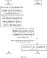
- FIG. 2A and FIG. 2B are a flowchart of Embodiment 2 of a downlink information transmission method according to this application. As shown in FIG. 2A and FIG. 2B , the downlink information transmission methods include the following specific implementation steps.
- S201 Encode to-be-sent information into at least two transport blocks, where each transport block carries the to-be-sent information, and each transport block can be independently decoded.
- to-be-sent information bits may be encoded into N transport blocks (N is greater than or equal to 2), and CRC is added to each transport block, to implement independent decoding.
- S202 Map, based on pre-determined available time-frequency resources, the transport blocks to the available time-frequency resources in a sequence of "frequency domain first, time domain second", to obtain a time-frequency resource of each transport block.
- a base station determines, based on the pre-determined available time-frequency resources, the time-frequency resource used to send each transport block, where a first to an N th of the N transport blocks are mapped to the available time-frequency resources in the sequence of "frequency domain first, time domain second".
- the base station first needs to obtain the available time-frequency resources and the quantity of to-be-sent transport blocks (the quantity of transport blocks is greater than 2).
- the base station maps the transport blocks in the sequence of "frequency domain first, time domain second". In other words, the base station first map the transport blocks in frequency domain, and after transport blocks are mapped to all available frequency domain resources, if there is still a transport block needing to be transmitted, the base station maps the transport block to a frequency domain resource in a next time domain location, so that an information bit transmission latency can be effectively reduced.
- the base station may determine a relationship between the time-frequency resources corresponding to the transport blocks, and the base station may obtain a time-frequency resource parameter based on this.
- the base station obtains unit time-frequency resource information occupied by each transport block, where the unit time-frequency resource information is used to indicate a size of a frequency domain resource occupied by the transport block and a size of a time domain resource occupied by the transport block.
- the base station or user equipment may determine, based on a size of each transport block, a frequency domain resource and/or a time domain resource that are/is occupied by the transport block.
- S203 Send downlink resource indication information to user equipment, where the downlink resource indication information includes a quantity of transport blocks, a first time-frequency resource location, and a location parameter corresponding to another transport block.
- M 1
- the first time-frequency resource location includes a time domain start location and/or a frequency domain start location of the time-frequency resource occupied by the first transport block.
- the first time-frequency resource location may directly indicate a time domain location range and/or a frequency domain location range of the first transport block.
- the time domain start location of the first transport block may alternatively be indicated in the foregoing manner.
- the frequency domain start location of the first transport block may alternatively be indicated in the foregoing manner.
- the specific time domain location range and frequency domain location range may be determined by using the unit time-frequency resource information occupied by each transport block. After receiving the downlink resource indication information, the user equipment determines the time-frequency resource location of the first transport block, and receives the transport block in the corresponding location.
- the first time-frequency resource location includes a time domain start location and a time domain end location and/or a frequency domain start location and a frequency domain end location of the first transport block sent by the base station.
- the downlink resource indication information is used to indicate the time domain start location and the time domain end location and/or the frequency domain start location and the frequency domain end location that are occupied by the first transport block.
- the first time-frequency resource location directly indicates the time domain start location, the time domain end location, the frequency domain start location, and the frequency domain end location of the first transport block.
- the time domain start location and the time domain end location of the first transport block may alternatively be indicated in the foregoing manner.
- the frequency domain start location and the frequency domain end location of the first transport block may alternatively be indicated in the foregoing manner.
- the start location and the end location of the first transport block are clearly indicated, and the time-frequency resource location of the transport block can be obtained without obtaining the unit time-frequency resource information occupied by each transport block.
- a location parameter of the transport block is carried in the downlink resource indication, and notified to the user equipment.
- the location parameter of the transport block includes a frequency domain interval between the transport block and an M th transport block or a frequency domain interval between two neighboring transport blocks.
- the relationship that is between a time-frequency resource location of the another transport block and a time-frequency resource location of the M th transport block and that is indicated in the time-frequency resource parameter of the transport block includes at least the foregoing two manners.
- the location parameter of the transport block indicates a frequency domain interval between a time-frequency resource location of each transport block and the time-frequency resource location of the M th transport block or indicates the frequency domain interval between two neighboring transport blocks.
- This solution is not limited to the foregoing two indication manners, and another indication manner may be used, provided that the time-frequency resource location of the another transport block can be determined based on the time-frequency resource location of the M th transport block.
- the base station After sending the downlink resource indication information to the user equipment, the base station sends the at least two transport blocks that are mapped to the corresponding time-frequency resources. After sending a corresponding transport block on at least one time-frequency resource, in a process of sending a remaining transport block, the base station constantly receives feedback information from the user equipment, and the base station determines, based on the feedback information, whether to send the remaining transport block.
- the base station sends the first transport block in the first time-frequency resource location. If there is only one transport block in a time domain location in the first time-frequency resource location, only one transport block is sent. If there are a plurality of transport blocks in a plurality of frequency domain resources corresponding to the time domain location in the first time-frequency resource location, the plurality of transport blocks on the plurality of frequency resources are all sent in the time domain location.
- the user equipment If the user equipment receives the transport block and successfully decodes the transport block to obtain the information bits, the user equipment returns an acknowledgement message. In other words, the base station receives the acknowledgement message that indicates successful receiving and that is sent by the user equipment, and the base station no longer continues to send the another transport block. If the base station does not receive the acknowledgement message returned by the user equipment, the base station needs to continue to send the transport block, that is, send the corresponding transport block in a remaining time-frequency resource location in a chronological sequence of time domain until the acknowledgement message returned by the user equipment is received.
- S205 Receive, in the first time-frequency resource location, a first transport block sent by the base station.
- S206 Demodulate and decode the first transport block.
- S207 If the first transport block fails to be demodulated or decoded, determine, based on the first time-frequency resource location and the location parameter corresponding to the another transport block, a time-frequency resource location corresponding to a next transport block sent by the base station, and obtain the transport block that is received in the time-frequency resource location.
- S208 Jointly demodulate and decode the transport block and all previously received transport blocks, if the transport block and all the previously received transport blocks fail to be demodulated or decoded, determine, based on the first time-frequency resource location and the location parameter corresponding to the another transport block, a resource location corresponding to a next transport block, obtain the transport block that is received in the time-frequency resource location, and repeat this step until a received transport block is successfully demodulated and decoded or all transport blocks sent by the base station are received.
- the user equipment first receives, in the first time-frequency resource location, the first transport block that is sent by the base station to the user equipment, and then demodulates and decodes the received first transport block. If the first transport block is successfully demodulated and decoded, the user equipment returns the acknowledgement message to the base station, and the user equipment does not need to obtain a resource of a subsequent transport block that is not received, and does not need to receive the transport block that is not received.
- the user equipment determines a time-frequency resource location of a next transport block (that is, a second transport block) based on the first time-frequency resource location and the location parameter of the another transport block, then receives, in the time-frequency resource location, the second transport block sent by the base station, and then performs joint decoding processing on the first transport block and the second transport block. If the first transport block and the second transport block are successfully demodulated and decoded, the user equipment returns the acknowledgement message to the base station, and the process ends.
- a next transport block that is, a second transport block
- the user equipment determines a time-frequency resource location of a next transport block based on the location parameter, receives the next transport block, and jointly demodulates and decodes all received transport blocks. In other words, the process is repeated until demodulation and decoding succeed, or the process ends after all transport blocks are received but fail to be demodulated or decoded.
- the first time-frequency resource location includes the time domain start location and/or the frequency domain start location in which the first transport block is sent, and the user equipment needs to pre-obtain the unit time-frequency resource information occupied by each transport block.
- the unit time-frequency resource information is used to indicate the size of the frequency domain resource occupied by the transport block and the size of the time domain resource occupied by the transport block.
- a manner of determining the time-frequency resource location of the next transport block in S207 is: determining, based on the time domain start location and the frequency domain start location of the first transport block, the unit time-frequency resource information, and the location parameter corresponding to the another transport block, a time domain start location and/or a frequency domain start location that are/is occupied by the next transport block sent by the base station.
- the first time-frequency resource location includes the time domain start location and the time domain end location and/or the frequency domain start location and the frequency domain end location of the first transport block
- an implementation of determining the time-frequency resource location corresponding to the next transport block sent by the base station in S207 is: determining, based on the location parameter corresponding to the another transport block and the time domain start location and the time domain end location of the first transport block, a time domain start location and a time domain end location that correspond to the next transport block sent by the base station; and/or determining, based on the location parameter corresponding to the another transport block, the frequency domain start location, and the frequency domain end location, a frequency domain start location and a frequency domain end location that correspond to the next transport block sent by the base station.
- the frequency domain start location and the frequency domain end location may be specifically identified by using numbers.
- the available time-frequency resources may be numbered by using virtual numbers.
- a numbering method is: numbering frequency domain resources from a first available time domain resource in ascending sequence of frequency domain, and after all frequency domain resources in one time domain resource are numbered, numbering frequency domain resources in a next time domain resource in ascending sequence, where numbers are positive integers in ascending sequence.
- the first time-frequency resource location may be directly represented by using a start number and an end number, and generally, a start number of a frequency domain resource of the first transport block is the smallest.
- a relationship between a time-frequency resource of the another transport block and the time-frequency resource of the first transport block may alternatively be represented by using a number difference, and this is not specifically limited in this application.
- S209 Send an acknowledgement message to the base station if a transport block is successfully demodulated and decoded.
- S210 Send a failure message to the base station if all transport blocks sent by the base station fail to be jointly demodulated or decoded.
- steps S209 and S210 Only one of steps S209 and S210 is performed. If the user equipment successfully performs demodulation and decoding, the user equipment returns the acknowledgement message to the base station, and notifies the base station that the information is successfully received; if the user equipment fails in demodulation or decoding, the user equipment feeds back the failure message to the base station, so that the base station can re-send a transport block or perform corresponding processing.
- the user equipment determines the first time-frequency resource location of the first transport block based on the time-frequency resource location of the M th transport block and the obtained location parameter of the time-frequency resource of the another transport block, and then receives the first transport block, and decodes the first transport block. If the first transport block fails to be decoded, the user equipment determines the time-frequency resource location of the second transport block based on the time-frequency resource location of the M th transport block and the location parameter of the another transport block, and so on, to implement information transmission.
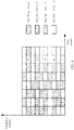
- a time-frequency resource is a resource including one subframe in time domain and full available downlink bandwidth in frequency domain.
- the time-frequency resource may be divided into N t ⁇ N f grids.
- a length of one subframe is evenly divided into N t slots on a time axis and evenly divided into N f grids on a frequency axis, and each grid represents one RB.
- the RB lasts for one slot in time domain, and occupies a plurality of subcarriers in frequency domain.
- one RB occupies one slot and lasts for 0.5 ms in time domain, and occupies 12 subcarriers (when a subcarrier spacing is 15 kHz) or 24 subcarriers (when a subcarrier spacing is 7.5 kHz) in frequency domain.
- a specific implementation of the downlink information transmission scheme is:
- the base station sends downlink resource indication information to the user equipment.
- the downlink resource indication information includes a quantity N of downlink data channel transport blocks sent by the base station to the user equipment, a time-frequency resource location of a first transport block, and location parameters of time-frequency resources of N-1 remaining downlink transport blocks.
- the base station scrambles a cyclic redundancy check (English: Cyclic Redundancy Check, CRC for short) code by using an identifier (that is, a terminal identifier) of user equipment needing to be scheduled, adds the CRC code to resource indication information, performs encoding, rate matching, scrambling, modulation, and interleaving, maps the resource indication information to a downlink control region, and sends the resource indication information to the user equipment.
- CRC Cyclic Redundancy Check
- the base station sends downlink data information to the user equipment in the downlink data region based on the downlink resource indication information, that is, sends the plurality of transport blocks on respective time-frequency resources.
- the base station first encodes original information bits into N transport blocks that can be independently decoded, where a size of a transport block is S.
- the base station maps one transport block to a location ( i 1 ; j 1 ) of the first transport block in the resource indication.
- the base station maps the N -1 transport blocks to the corresponding time-frequency resource locations based on the location parameters of the time-frequency resources of the N -1 remaining downlink transport blocks.
- a specific mapping process is as follows:
- the location parameters of the time-frequency resources of the N -1 remaining downlink transport blocks are a frequency domain interval G (G indicates a quantity of RBs between an end location of a previous transport block and a start location of a current transport block) between two neighboring transport blocks.
- G indicates a quantity of RBs between an end location of a previous transport block and a start location of a current transport block
- the N -1 remaining transport blocks are mapped to the time-frequency resources in a sequence of "frequency domain first, time domain second" based on the start location ( i 1 , j 1 ) of the first transport block and the frequency domain interval G between two neighboring transport blocks.
- FIG. 3 is a specific schematic diagram of mapping transport blocks to a downlink data region according to this application.
- the base station schedules four user equipments UE 1 to UE 4 in one subframe, and given resource indication information of the user equipments according to step 1 is shown in the following table:
- User equipment N i 1 , j 1
- G Size S of a transport block (specified in other downlink control information) UE 1 2 (1,6) 0 2 UE 2 4 (2, 1) 2 1 UE 3 8 (2, 3) 4 1 UE 4 6 (3, 7) 8 1
- the location parameters of the time-frequency resources of the N -1 remaining downlink transport blocks each are a quantity X of transport blocks in each slot, and a frequency interval G between neighboring transport blocks in each scheduling period is configured by using a higher layer.
- the N -1 remaining downlink transport blocks are mapped to the time-frequency resources in the sequence of "frequency domain first, time domain second" based on the start location ( i 1 , j 1 ) of the first transport block and the quantity X of transport blocks transmitted in each scheduling period.
- FIG. 4 is a specific schematic diagram of mapping transport blocks to a downlink data region according to this application.
- the base station schedules four user equipments UE 1 to UE 4 in 1 ms, and given resource indication information of the user equipments according to step 1 is shown the following table:
- User equipment N i 1 , j 1
- X G higher layer configuration
- Size S of a transport block (specified in other downlink control information)
- UE 1 4 (1,6) 2 1 1 1 UE 2 8 (1, 3) 4 1 1 UE 3 9 (3,2) 3 1 2 UE 4 11 (6, 9) 5 1 1
- UE 1 4 (1,6) 2 1 1 1 UE 2 8 (1, 3) 4 1 1 1 UE 3 9 (3,2) 3 1 2 UE 4 11 (6, 9) 5 1 1
- the location parameters of the time-frequency resources of the N -1 remaining downlink transport blocks each may be the frequency domain interval G between two neighboring transport blocks in the first example or the quantity X of transport blocks in each scheduling period in the second example, or may be another parameter. Which parameter is specifically selected is stipulated in the standard. If it is stipulated in the standard that a plurality of parameters may be used at the same time, indication information is added to the downlink resource indication information to indicate which parameter is used as each of the location parameters of the time-frequency resources of the N -1 remaining downlink transport blocks. Further, the base station sends mapped data information to the user equipment.
- the user equipment receives the downlink resource indication information.
- the user equipment performs blind detection on downlink control information in search space of the user equipment.
- the downlink resource indication information includes the quantity N of data channel transport blocks, the location information ( i 1 , j 1 ) of the time-frequency resource of the first transport block, and the location parameters of the time-frequency resources of the N -1 remaining downlink transport blocks.
- the user equipment does not detect the downlink resource allocation information, it indicates that the user equipment is not scheduled, and the user equipment does not need to receive any data information.
- the user equipment receives the transport block in the downlink data region.
- the user equipment first finds the first transport block based on the downlink resource indication information that is received in the foregoing solution, and then the user equipment demodulates and decodes the first transport block, including:
- the second transport block is found based on the location ( i 1 , j 1 ) of the time-frequency resource of the first transport block and the location parameters of the time-frequency resources of the N -1 remaining downlink transport blocks and according to a pre-defined mapping rule of "frequency domain first, time frequency second".
- the user equipment jointly decodes the first transport block and the second transport block, including:
- the location ( i k , j k ) of the k(k > 2) th transport block may be uniquely determined based on the location ( i 1 , j 1 ) of the time-frequency resource of the first transport block and the location parameters of the time-frequency resources of the N -1 remaining downlink transport blocks and according to a pre-defined mapping rule of "frequency domain first, time frequency second".
- the user equipment jointly decodes k transport blocks, including: if the k transport blocks are successfully decoded jointly, the user equipment does not process subsequent N - k transport blocks, feeds back ACK information to the base station, and ends current communication; or if the k transport blocks fail to be decoded, the user equipment continues to search for a next transport block; and repeats the process until an N th transport block is found.
- the user equipment jointly decodes the N transport blocks, including:
- the downlink resource indication information includes the quantity N of downlink data channel transport blocks, the time-frequency resource location information of the first downlink transport block, and the location parameters of the time-frequency resources of the N -1 remaining downlink transport blocks.
- the same information bits are encoded into the N transport blocks that can be independently decoded, and diversity transmission is performed on the transport blocks in the downlink data region, to improve reliability of a downlink data channel.
- the N transport blocks are mapped to the available resources based on a method of "frequency domain first, time domain second", so that a latency is minimized when reliability is improved.
- the downlink resource indication information includes only the quantity N of transport blocks, the location of the first transport block, the time-frequency resource location information of the first downlink transport block, and the location parameters of the time-frequency resources of the N -1 remaining downlink transport blocks, the locations of all transport blocks may be uniquely determined based on the time-frequency resource location information of the first downlink transport block and the location parameters of the time-frequency resources of the N -1 remaining downlink transport blocks and based on the pre-defined mapping mode of "frequency domain first, time domain second", and there is no need to notify the time-frequency resource location of each transport block, thereby reducing downlink control signaling overheads as far as possible.
- FIG. 5 is a schematic structural diagram of Embodiment 1 of a downlink information transmission apparatus according to this application. As shown in FIG. 5 , the downlink information transmission apparatus 10 includes:
- the downlink information transmission apparatus provided in this embodiment is configured to perform the technical solution on a base station side in any one of the foregoing method embodiments.
- Implementation principles and technical effects of the downlink information transmission apparatus are similar to those of the technical solution, and details are not described herein again.
- the processing module 11 is specifically configured to determine, based on pre-determined available time-frequency resources, the time-frequency resource used to send each transport block, where a first to an N th of the N transport blocks are mapped to the available time-frequency resources in a sequence of "frequency domain first, time domain second".
- Each of the N transport blocks obtained by the processing module 11 through encoding carries the to-be-sent information, and each transport block can be independently decoded; or a first transport block in the N transport blocks obtained by the processing module 11 through encoding carries the to-be-sent information, and the first transport block can be independently decoded; and a remaining transport block in the N transport blocks carries redundancy information or check information of the first transport block, and the remaining transport block and the first transport block can be jointly decoded.
- the apparatus 10 further includes a receiving module 13; and the sending module 12 is specifically configured to: send the transport blocks on the determined time-frequency resources in a chronological sequence in time domain until the receiving module receives an acknowledgement message sent by the user equipment.
- M 1, and the downlink resource indication information sent by the sending module 12 to the user equipment is used to indicate a time domain start location and/or a frequency domain start location of a time-frequency resource occupied by the first transport block.
- the processing module 11 is further configured to: before determining the time-frequency resource used to send each transport block, obtain unit time-frequency resource information occupied by each transport block, where the unit time-frequency resource information is used to indicate a size of a frequency domain resource occupied by the transport block and a size of a time domain resource occupied by the transport block.
- M 1, and the downlink resource indication information sent by the sending module 12 to the user equipment is used to indicate a time domain start location and a time domain end location and/or a frequency domain start location and a frequency domain end location that are occupied by the first transport block.
- the downlink resource indication information sent by the sending module 12 to the user equipment further includes a location parameter of a time-frequency resource of a transport block other than the M th transport block, and the location parameter of the transport block is used to indicate a relationship between a time-frequency resource location of the transport block and the time-frequency resource location of the M th transport block or is used to indicate a relationship between time-frequency resource locations of two neighboring transport blocks.
- the downlink resource indication information further includes the quantity of transport blocks.
- the location parameter that is of the transport block and that is sent by the sending module 12 to the user equipment includes a frequency domain interval between the transport block and the M th transport block or a frequency domain interval between two neighboring transport blocks.
- the downlink information transmission apparatus provided in this embodiment is configured to perform the technical solution on the base station side in any one of the foregoing method embodiments. Implementation principles and technical effects of the downlink information transmission apparatus are similar to those of the technical solution, and details are not described herein again.
- FIG. 6 is a schematic structural diagram of Embodiment 2 of a downlink information transmission apparatus according to this application. As shown in FIG. 6 , the downlink information transmission apparatus 20 includes:
- the downlink information transmission apparatus provided in this embodiment is configured to perform the technical solution on a user equipment side in any one of the foregoing method embodiments.
- Implementation principles and technical effects of the downlink information transmission apparatus are similar to those of the technical solution, and details are not described herein again.
- the downlink resource indication information received by the receiving module 21 further includes a location parameter of a time-frequency resource of a transport block other than the M th transport block, and the location parameter of the transport block is used to indicate a relationship between a time-frequency resource location of the transport block and the time-frequency resource location of the M th transport block or is used to indicate a relationship between time-frequency resource locations of two neighboring transport blocks.
- the downlink resource indication information further includes the quantity of transport blocks.
- M 1, and the downlink resource indication information is used to indicate a first time-frequency resource location occupied by the first transport block, the receiving module 21 is specifically configured to receive, in the first time-frequency resource location, the first transport block sent by the base station;
- the processing module 22 is further configured to obtain unit time-frequency resource information occupied by each transport block, where the unit time-frequency resource information is used to indicate a size of a frequency domain resource occupied by the transport block and a size of a time domain resource occupied by the transport block.
- the first time-frequency resource location includes a time domain start location and/or a frequency domain start location in which the first transport block is sent
- the processing module 22 is specifically configured to determine, based on the time domain start location and/or the frequency domain start location of the first transport block, the unit time-frequency resource information, and the location parameter corresponding to the another transport block, a time domain start location and/or a frequency domain start location that are/is occupied by the next transport block sent by the base station.
- the first time-frequency resource location includes a time domain start location and a time domain end location and/or a frequency domain start location and a frequency domain end location of the first transport block; and the processing module 22 is specifically configured to determine, based on the location parameter corresponding to the another transport block and the time domain start location and the time domain end location of the first transport block, a time domain start location and a time domain end location that correspond to the next transport block sent by the base station; and/or determine, based on the location parameter corresponding to the another transport block, the frequency domain start location, and the frequency domain end location, a frequency domain start location and a frequency domain end location that correspond to the next transport block sent by the base station.
- M > 1
- the processing module 22 is specifically configured to determine a first time-frequency resource location of a first transport block based on the time-frequency resource location of the M th transport block and the obtained location parameter of the time-frequency resource of the another transport block;
- the location parameter that is of the transport block and that is obtained by the processing module 22 includes a frequency domain interval between the transport block and the M th transport block or a frequency domain interval between two neighboring transport blocks.
- the downlink information transmission apparatus 20 provided in the foregoing implementation is configured to perform the technical solution on the user equipment side in any one of the foregoing method embodiments. Implementation principles and technical effects of the downlink information transmission apparatus are similar to those of the technical solution, and details are not described herein again.
- FIG. 7 is a schematic structural diagram of Embodiment 3 of a downlink information transmission apparatus according to this application. As shown in FIG. 7 , based on Embodiment 2, the downlink information transmission apparatus 20 further includes a sending module 23, where
- the downlink information transmission apparatus 20 provided in this embodiment is configured to perform the technical solution on the user equipment side in any one of the foregoing method embodiments. Implementation principles and technical effects of the downlink information transmission apparatus are similar to those of the technical solution, and details are not described herein again.
- FIG. 8 is a schematic structural diagram of Embodiment 1 of a base station according to this application. As shown in FIG. 8 , the base station 30 includes:
- the processor 32 is specifically configured to determine, based on pre-determined available time-frequency resources, the time-frequency resource used to send each transport block, where a first to an N th of the N transport blocks are mapped to the available time-frequency resources in a sequence of "frequency domain first, time domain second".
- Each of the N transport blocks obtained by the processor 32 through encoding carries the to-be-sent information, and each transport block can be independently decoded; or a first transport block in the N transport blocks obtained by the processor 32 through encoding carries the to-be-sent information, and the first transport block can be independently decoded; and a remaining transport block in the N transport blocks carries redundancy information or check information of the first transport block, and the remaining transport block and the first transport block can be jointly decoded.
- the base station further includes a receiver 34; and the transmitter 33 is specifically configured to: send the transport blocks on the determined time-frequency resources in a chronological sequence in time domain until the receiver receives an acknowledgement message sent by the user equipment.
- M 1, and the downlink resource indication information sent by the transmitter 33 to the user equipment is used to indicate a time domain start location and/or a frequency domain start location of a time-frequency resource occupied by the first transport block.
- the processor 32 is further configured to: before determining the time-frequency resource used to send each transport block, obtain unit time-frequency resource information occupied by each transport block, where the unit time-frequency resource information is used to indicate a size of a frequency domain resource occupied by the transport block and a size of a time domain resource occupied by the transport block.
- M 1, and the downlink resource indication information sent by the transmitter 33 to the user equipment is used to indicate a time domain start location and a time domain end location and/or a frequency domain start location and a frequency domain end location that are occupied by the first transport block.
- the downlink resource indication information sent by the transmitter 33 to the user equipment further includes a location parameter of a time-frequency resource of a transport block other than the M th transport block, and the location parameter of the transport block is used to indicate a relationship between a time-frequency resource location of the transport block and the time-frequency resource location of the M th transport block or is used to indicate a relationship between time-frequency resource locations of two neighboring transport blocks.
- the downlink resource allocation further includes the quantity of transport blocks.
- the location parameter that is of the transport block and that is sent by the transmitter 33 to the user equipment includes a frequency domain interval between the transport block and the M th transport block or a frequency domain interval between two neighboring transport blocks.
- the base station provided in this embodiment is configured to perform the technical solution on the base station side in any one of the foregoing method embodiments.
- Implementation principles and technical effects of the based station are similar to those of the technical solution, and details are not described herein again.
- FIG. 9 is a schematic structural diagram of Embodiment 1 of user equipment according to this application.
- the user equipment 40 includes:
- the downlink resource indication information received by the receiver 42 further includes a location parameter of a time-frequency resource of a transport block other than the M th transport block, and the location parameter of the transport block is used to indicate a relationship between a time-frequency resource location of the transport block and the time-frequency resource location of the M th transport block or is used to indicate a relationship between time-frequency resource locations of two neighboring transport blocks
- the downlink resource allocation further includes the quantity of transport blocks.
- M 1
- the downlink resource indication information is used to indicate a first time-frequency resource location occupied by the first transport block
- the receiver 42 is specifically configured to receive, in the first time-frequency resource location, the first transport block sent by the base station;
- the processor 43 is further configured to obtain unit time-frequency resource information occupied by each transport block, where the unit time-frequency resource information is used to indicate a size of a frequency domain resource occupied by the transport block and a size of a time domain resource occupied by the transport block.
- the first time-frequency resource location includes a time domain start location and/or a frequency domain start location in which the first transport block is sent
- the processor 43 is specifically configured to determine, based on the time domain start location and/or the frequency domain start location of the first transport block, the unit time-frequency resource information, and the location parameter corresponding to the another transport block, a time domain start location and/or a frequency domain start location that are/is occupied by the next transport block sent by the base station.
- the first time-frequency resource location includes a time domain start location and a time domain end location and/or a frequency domain start location and a frequency domain end location of the first transport block; and the processor 43 is specifically configured to determine, based on the location parameter corresponding to the another transport block and the time domain start location and the time domain end location of the first transport block, a time domain start location and a time domain end location that correspond to the next transport block sent by the base station; and/or determine, based on the location parameter corresponding to the another transport block, the frequency domain start location, and the frequency domain end location, a frequency domain start location and a frequency domain end location that correspond to the next transport block sent by the base station.
- M > 1
- the processor 43 is specifically configured to determine a first time-frequency resource location of a first transport block based on the time-frequency resource location of the M th transport block and the obtained location parameter of the time-frequency resource of the another transport block;
- the location parameter that is of the transport block and that is obtained by the processor 43 includes a frequency domain interval between the transport block and the M th transport block or a frequency domain interval between two neighboring transport blocks.
- the user equipment further includes: a transmitter 44, configured to send an acknowledgement message to the base station if the processor 43 successfully demodulates and decodes a transport block.
- the user equipment further includes: a transmitter 44, configured to send a failure message to the base station if the processor 43 fails to jointly demodulate or decode all transport blocks sent by the base station.
- a transmitter 44 configured to send a failure message to the base station if the processor 43 fails to jointly demodulate or decode all transport blocks sent by the base station.
- the user equipment provided in this embodiment is configured to perform the technical solution on the user equipment side in any one of the foregoing method embodiments. Implementation principles and technical effects of the user equipment are similar to those of the technical solution, and details are not described herein again.
- This application further provides a storage medium, including a readable storage medium and a computer program, where the computer program is used to implement any downlink information transmission method provided on a base station side.
- This application further provides a storage medium, including a readable storage medium and a computer program, where the computer program is used to implement any downlink information transmission method provided on a user equipment side.
- the program product includes a computer program (that is, an execution instruction), and the computer program is stored in a readable storage medium.
- At least one processor of a base station can read the computer program from the readable storage medium, and the at least one processor executes the computer program, so that the base station implements the downlink information transmission method provided in the foregoing implementations.
- the program product includes a computer program (that is, an execution instruction), and the computer program is stored in a readable storage medium.
- At least one processor of user equipment can read the computer program from the readable storage medium, and the at least one processor executes the computer program, so that the user equipment implements the downlink information transmission method provided in the foregoing implementations.
- the processor may be a central processing unit (English: Central Processing Unit, CPU for short), or may be another general purpose processor, a digital signal processor (English: Digital Signal Processor, DSP for short), an application specific integrated circuit (English: Application Specific Integrated Circuit, ASIC for short), or the like.
- the general purpose processor may be a microprocessor, or the processor may be any conventional processor or the like. The steps of the method disclosed with reference to the embodiments of this application may be directly performed by a hardware processor, or may be performed by using a combination of hardware in the processor and a software module.
- the memory includes: a read-only memory (English: read-only memory, ROM for short), a RAM, a flash memory, a hard disk, a solid state disk, a magnetic tape (English: magnetic tape), a floppy disk (English: floppy disk), an optical disc (English: optical disc), and any combination thereof.
Landscapes
- Engineering & Computer Science (AREA)
- Signal Processing (AREA)
- Computer Networks & Wireless Communication (AREA)
- Quality & Reliability (AREA)
- Mobile Radio Communication Systems (AREA)
Applications Claiming Priority (2)
| Application Number | Priority Date | Filing Date | Title |
|---|---|---|---|
| CN201610965310.6A CN108024347B (zh) | 2016-11-04 | 2016-11-04 | 下行信息传输方法、装置和设备 |
| PCT/CN2017/103991 WO2018082419A1 (zh) | 2016-11-04 | 2017-09-28 | 下行信息传输方法、装置和设备 |
Publications (3)
| Publication Number | Publication Date |
|---|---|
| EP3525538A1 EP3525538A1 (en) | 2019-08-14 |
| EP3525538A4 EP3525538A4 (en) | 2019-10-23 |
| EP3525538B1 true EP3525538B1 (en) | 2022-12-07 |
Family
ID=62075752
Family Applications (1)
| Application Number | Title | Priority Date | Filing Date |
|---|---|---|---|
| EP17867789.4A Active EP3525538B1 (en) | 2016-11-04 | 2017-09-28 | Downlink information transmission method, apparatus and device |
Country Status (4)
| Country | Link |
|---|---|
| US (1) | US11038620B2 (zh) |
| EP (1) | EP3525538B1 (zh) |
| CN (1) | CN108024347B (zh) |
| WO (1) | WO2018082419A1 (zh) |
Families Citing this family (11)
| Publication number | Priority date | Publication date | Assignee | Title |
|---|---|---|---|---|
| CN110492969B (zh) * | 2018-05-11 | 2022-04-29 | 中兴通讯股份有限公司 | 信号发送、接收方法及装置 |
| EP3829233A4 (en) * | 2018-07-27 | 2022-03-16 | Beijing Xiaomi Mobile Software Co., Ltd. | DATA TRANSMISSION METHOD, DEVICE, EQUIPMENT, SYSTEM, AND STORAGE MEDIA |
| CN112840717B (zh) * | 2018-09-28 | 2023-02-28 | 华为技术有限公司 | 传输数据的方法、终端设备和网络设备 |
| CN110971365A (zh) * | 2018-09-28 | 2020-04-07 | 北京展讯高科通信技术有限公司 | 信令与数据的多次接收、传输方法及装置、终端 |
| CN109982433B (zh) * | 2019-03-05 | 2020-01-07 | 深圳大学 | 基于启发式算法的固定帧长度的urllc系统的资源优化方法 |
| US20220166595A1 (en) * | 2019-03-28 | 2022-05-26 | Nokia Technologies Oy | Preconfigured radio link switching for bandwidth parts |
| WO2021027603A1 (zh) * | 2019-08-12 | 2021-02-18 | 华为技术有限公司 | 一种指示频域资源的方法及装置 |
| CN112637954B (zh) * | 2019-09-24 | 2023-03-24 | 大唐移动通信设备有限公司 | 一种资源位置指示方法、基站及终端 |
| US11792824B2 (en) * | 2020-03-30 | 2023-10-17 | Qualcomm Incorporated | Multicast feedback and retransmission for transport block grouping |
| CN116671213A (zh) * | 2021-01-07 | 2023-08-29 | 华为技术有限公司 | 确定发送功率的方法及装置 |
| CN115696272A (zh) * | 2021-07-29 | 2023-02-03 | 华为技术有限公司 | 一种信息发送方法、接收方法及通信装置 |
Family Cites Families (19)
| Publication number | Priority date | Publication date | Assignee | Title |
|---|---|---|---|---|
| KR101570350B1 (ko) * | 2008-02-22 | 2015-11-19 | 엘지전자 주식회사 | 동적 전송시간간격 할당방법 |
| EP2106057A1 (en) * | 2008-03-25 | 2009-09-30 | Panasonic Corporation | Resource allocation size dependent transport block size signalling |
| CN101834692B (zh) * | 2009-03-09 | 2013-06-12 | 电信科学技术研究院 | 载波聚合系统中的信令指示方法及基站和终端 |
| CN104065453B (zh) * | 2009-09-30 | 2017-11-28 | 华为技术有限公司 | 控制信息的发送和接收方法、装置和通信系统 |
| CN102083223A (zh) * | 2010-03-05 | 2011-06-01 | 大唐移动通信设备有限公司 | 一种发送dci和上行传输的方法、系统及装置 |
| JP5265616B2 (ja) * | 2010-05-18 | 2013-08-14 | 株式会社エヌ・ティ・ティ・ドコモ | 無線通信システム |
| KR101771550B1 (ko) * | 2010-10-15 | 2017-08-29 | 주식회사 골드피크이노베이션즈 | Ack/nack 신호 송수신 방법 및 장치 |
| US8681651B2 (en) * | 2010-11-05 | 2014-03-25 | Qualcomm Incorporated | Reference signal reception and channel state information determination for multiple nodes in a wireless communication network |
| US9247563B2 (en) * | 2011-12-23 | 2016-01-26 | Blackberry Limited | Method implemented in a user equipment |
| WO2013123977A1 (en) * | 2012-02-21 | 2013-08-29 | Telefonaktiebolaget L M Ericsson (Publ) | Retransmission protocol feedback handling with multiple feedback times |
| CN104144030B (zh) * | 2013-05-09 | 2019-05-10 | 中兴通讯股份有限公司 | 数据发送、接收方法、数据发送及接收端 |
| KR102058563B1 (ko) * | 2013-08-07 | 2019-12-24 | 인터디지탈 패튼 홀딩스, 인크 | 디바이스 대 디바이스 통신을 위한 분산형 스케줄링 |
| EP3304994B1 (en) * | 2015-06-05 | 2021-03-17 | Telefonaktiebolaget LM Ericsson (PUBL) | Sending a configuration message and reporting channel information on pucch in pcell and in scell |
| CN105162553B (zh) * | 2015-08-14 | 2018-09-07 | 宇龙计算机通信科技(深圳)有限公司 | 一种传输块类型信令指示方法及系统 |
| WO2017171408A2 (ko) * | 2016-03-29 | 2017-10-05 | 엘지전자(주) | 무선 통신 시스템에서 채널 상태 정보를 전송하는 방법 및 이를 위한 장치 |
| EP3437408A1 (en) * | 2016-03-30 | 2019-02-06 | Interdigital Patent Holdings, Inc. | Method and procedures for downlink physical channels to reduce latency in an lte advanced system |
| KR101995435B1 (ko) * | 2016-04-22 | 2019-07-02 | 엘지전자 주식회사 | 무선통신 시스템에서 harq ack/nack 신호를 전송/수신하는 방법 및 이를 위한 장치 |
| EP3536040B1 (en) * | 2016-11-04 | 2021-10-27 | Telefonaktiebolaget LM Ericsson (PUBL) | System information for narrowband |
| EP3512137B1 (en) * | 2017-11-16 | 2021-10-20 | LG Electronics Inc. | Pbch transmitting method and transmitting device, and pbch receiving method and receiving device |
-
2016
- 2016-11-04 CN CN201610965310.6A patent/CN108024347B/zh active Active
-
2017
- 2017-09-28 EP EP17867789.4A patent/EP3525538B1/en active Active
- 2017-09-28 WO PCT/CN2017/103991 patent/WO2018082419A1/zh unknown
-
2019
- 2019-05-06 US US16/404,364 patent/US11038620B2/en active Active
Also Published As
| Publication number | Publication date |
|---|---|
| WO2018082419A1 (zh) | 2018-05-11 |
| US20190260502A1 (en) | 2019-08-22 |
| CN108024347B (zh) | 2022-02-08 |
| US11038620B2 (en) | 2021-06-15 |
| CN108024347A (zh) | 2018-05-11 |
| EP3525538A1 (en) | 2019-08-14 |
| EP3525538A4 (en) | 2019-10-23 |
Similar Documents
| Publication | Publication Date | Title |
|---|---|---|
| EP3525538B1 (en) | Downlink information transmission method, apparatus and device | |
| EP3547777B1 (en) | Method and apparatus for wireless communication | |
| US9554378B2 (en) | Communications method, base station, and mobile terminal | |
| EP3641180B1 (en) | Base station device, terminal device, wireless communication system, and communication method | |
| EP3579473B1 (en) | Data transmission method and related devices | |
| CN116405165A (zh) | 发送harq-ack/nack的方法和设备及下行传输方法和设备 | |
| EP3506538B1 (en) | Method, network apparatus and terminal apparatus for grant-free transmission | |
| US20180146474A1 (en) | Uplink data transmission method and device | |
| EP3297353B1 (en) | Resource allocation information indication method, base station and user equipment | |
| EP3425981B1 (en) | Resource allocation method and network device | |
| WO2013107364A1 (zh) | 下行控制信息的发送、下行控制信道的检测方法及装置 | |
| US20210337528A1 (en) | Network access node and client device for indication of multiple data channels in a single control message | |
| US20220368471A1 (en) | Method and apparatus for nack-only reporting in rrc idle and inactive states | |
| WO2018228236A1 (zh) | 数据传输方法和装置 | |
| CN109392011B (zh) | 一种信息的发送方法及设备 | |
| EP2192813A1 (en) | Method and apparatus for releasing reserved resources | |
| JP2011249915A (ja) | 無線通信装置及び無線通信方法 | |
| CN116762308A (zh) | 用于harq-ack码本确定的方法及设备 | |
| KR101670745B1 (ko) | 광대역 무선 접속 시스템에서의 자원할당 방법 | |
| CN116964969A (zh) | 用于基于仅nack的harq-ack反馈复用的方法及设备 |
Legal Events
| Date | Code | Title | Description |
|---|---|---|---|
| STAA | Information on the status of an ep patent application or granted ep patent |
Free format text: STATUS: THE INTERNATIONAL PUBLICATION HAS BEEN MADE |
|
| PUAI | Public reference made under article 153(3) epc to a published international application that has entered the european phase |
Free format text: ORIGINAL CODE: 0009012 |
|
| STAA | Information on the status of an ep patent application or granted ep patent |
Free format text: STATUS: REQUEST FOR EXAMINATION WAS MADE |
|
| 17P | Request for examination filed |
Effective date: 20190510 |
|
| AK | Designated contracting states |
Kind code of ref document: A1 Designated state(s): AL AT BE BG CH CY CZ DE DK EE ES FI FR GB GR HR HU IE IS IT LI LT LU LV MC MK MT NL NO PL PT RO RS SE SI SK SM TR |
|
| AX | Request for extension of the european patent |
Extension state: BA ME |
|
| A4 | Supplementary search report drawn up and despatched |
Effective date: 20190920 |
|
| RIC1 | Information provided on ipc code assigned before grant |
Ipc: H04L 1/08 20060101ALI20190916BHEP Ipc: H04L 5/00 20060101ALI20190916BHEP Ipc: H04W 72/08 20090101ALI20190916BHEP Ipc: H04L 1/00 20060101ALI20190916BHEP Ipc: H04L 1/18 20060101ALI20190916BHEP Ipc: H04L 1/02 20060101ALI20190916BHEP Ipc: H04W 72/04 20090101AFI20190916BHEP |
|
| DAV | Request for validation of the european patent (deleted) | ||
| DAX | Request for extension of the european patent (deleted) | ||
| STAA | Information on the status of an ep patent application or granted ep patent |
Free format text: STATUS: EXAMINATION IS IN PROGRESS |
|
| 17Q | First examination report despatched |
Effective date: 20210607 |
|
| STAA | Information on the status of an ep patent application or granted ep patent |
Free format text: STATUS: EXAMINATION IS IN PROGRESS |
|
| GRAP | Despatch of communication of intention to grant a patent |
Free format text: ORIGINAL CODE: EPIDOSNIGR1 |
|
| STAA | Information on the status of an ep patent application or granted ep patent |
Free format text: STATUS: GRANT OF PATENT IS INTENDED |
|
| INTG | Intention to grant announced |
Effective date: 20220728 |
|
| GRAS | Grant fee paid |
Free format text: ORIGINAL CODE: EPIDOSNIGR3 |
|
| GRAA | (expected) grant |
Free format text: ORIGINAL CODE: 0009210 |
|
| STAA | Information on the status of an ep patent application or granted ep patent |
Free format text: STATUS: THE PATENT HAS BEEN GRANTED |
|
| AK | Designated contracting states |
Kind code of ref document: B1 Designated state(s): AL AT BE BG CH CY CZ DE DK EE ES FI FR GB GR HR HU IE IS IT LI LT LU LV MC MK MT NL NO PL PT RO RS SE SI SK SM TR |
|
| REG | Reference to a national code |
Ref country code: GB Ref legal event code: FG4D |
|
| REG | Reference to a national code |
Ref country code: CH Ref legal event code: EP Ref country code: AT Ref legal event code: REF Ref document number: 1537077 Country of ref document: AT Kind code of ref document: T Effective date: 20221215 |
|
| REG | Reference to a national code |
Ref country code: DE Ref legal event code: R096 Ref document number: 602017064487 Country of ref document: DE |
|
| REG | Reference to a national code |
Ref country code: IE Ref legal event code: FG4D |
|
| REG | Reference to a national code |
Ref country code: LT Ref legal event code: MG9D |
|
| REG | Reference to a national code |
Ref country code: NL Ref legal event code: MP Effective date: 20221207 |
|
| PG25 | Lapsed in a contracting state [announced via postgrant information from national office to epo] |
Ref country code: SE Free format text: LAPSE BECAUSE OF FAILURE TO SUBMIT A TRANSLATION OF THE DESCRIPTION OR TO PAY THE FEE WITHIN THE PRESCRIBED TIME-LIMIT Effective date: 20221207 Ref country code: NO Free format text: LAPSE BECAUSE OF FAILURE TO SUBMIT A TRANSLATION OF THE DESCRIPTION OR TO PAY THE FEE WITHIN THE PRESCRIBED TIME-LIMIT Effective date: 20230307 Ref country code: LT Free format text: LAPSE BECAUSE OF FAILURE TO SUBMIT A TRANSLATION OF THE DESCRIPTION OR TO PAY THE FEE WITHIN THE PRESCRIBED TIME-LIMIT Effective date: 20221207 Ref country code: FI Free format text: LAPSE BECAUSE OF FAILURE TO SUBMIT A TRANSLATION OF THE DESCRIPTION OR TO PAY THE FEE WITHIN THE PRESCRIBED TIME-LIMIT Effective date: 20221207 Ref country code: ES Free format text: LAPSE BECAUSE OF FAILURE TO SUBMIT A TRANSLATION OF THE DESCRIPTION OR TO PAY THE FEE WITHIN THE PRESCRIBED TIME-LIMIT Effective date: 20221207 |
|
| REG | Reference to a national code |
Ref country code: AT Ref legal event code: MK05 Ref document number: 1537077 Country of ref document: AT Kind code of ref document: T Effective date: 20221207 |
|
| PG25 | Lapsed in a contracting state [announced via postgrant information from national office to epo] |
Ref country code: RS Free format text: LAPSE BECAUSE OF FAILURE TO SUBMIT A TRANSLATION OF THE DESCRIPTION OR TO PAY THE FEE WITHIN THE PRESCRIBED TIME-LIMIT Effective date: 20221207 Ref country code: PL Free format text: LAPSE BECAUSE OF FAILURE TO SUBMIT A TRANSLATION OF THE DESCRIPTION OR TO PAY THE FEE WITHIN THE PRESCRIBED TIME-LIMIT Effective date: 20221207 Ref country code: LV Free format text: LAPSE BECAUSE OF FAILURE TO SUBMIT A TRANSLATION OF THE DESCRIPTION OR TO PAY THE FEE WITHIN THE PRESCRIBED TIME-LIMIT Effective date: 20221207 Ref country code: HR Free format text: LAPSE BECAUSE OF FAILURE TO SUBMIT A TRANSLATION OF THE DESCRIPTION OR TO PAY THE FEE WITHIN THE PRESCRIBED TIME-LIMIT Effective date: 20221207 Ref country code: GR Free format text: LAPSE BECAUSE OF FAILURE TO SUBMIT A TRANSLATION OF THE DESCRIPTION OR TO PAY THE FEE WITHIN THE PRESCRIBED TIME-LIMIT Effective date: 20230308 |
|
| PG25 | Lapsed in a contracting state [announced via postgrant information from national office to epo] |
Ref country code: NL Free format text: LAPSE BECAUSE OF FAILURE TO SUBMIT A TRANSLATION OF THE DESCRIPTION OR TO PAY THE FEE WITHIN THE PRESCRIBED TIME-LIMIT Effective date: 20221207 |
|
| PG25 | Lapsed in a contracting state [announced via postgrant information from national office to epo] |
Ref country code: SM Free format text: LAPSE BECAUSE OF FAILURE TO SUBMIT A TRANSLATION OF THE DESCRIPTION OR TO PAY THE FEE WITHIN THE PRESCRIBED TIME-LIMIT Effective date: 20221207 Ref country code: RO Free format text: LAPSE BECAUSE OF FAILURE TO SUBMIT A TRANSLATION OF THE DESCRIPTION OR TO PAY THE FEE WITHIN THE PRESCRIBED TIME-LIMIT Effective date: 20221207 Ref country code: PT Free format text: LAPSE BECAUSE OF FAILURE TO SUBMIT A TRANSLATION OF THE DESCRIPTION OR TO PAY THE FEE WITHIN THE PRESCRIBED TIME-LIMIT Effective date: 20230410 Ref country code: EE Free format text: LAPSE BECAUSE OF FAILURE TO SUBMIT A TRANSLATION OF THE DESCRIPTION OR TO PAY THE FEE WITHIN THE PRESCRIBED TIME-LIMIT Effective date: 20221207 Ref country code: CZ Free format text: LAPSE BECAUSE OF FAILURE TO SUBMIT A TRANSLATION OF THE DESCRIPTION OR TO PAY THE FEE WITHIN THE PRESCRIBED TIME-LIMIT Effective date: 20221207 Ref country code: AT Free format text: LAPSE BECAUSE OF FAILURE TO SUBMIT A TRANSLATION OF THE DESCRIPTION OR TO PAY THE FEE WITHIN THE PRESCRIBED TIME-LIMIT Effective date: 20221207 |
|
| PG25 | Lapsed in a contracting state [announced via postgrant information from national office to epo] |
Ref country code: SK Free format text: LAPSE BECAUSE OF FAILURE TO SUBMIT A TRANSLATION OF THE DESCRIPTION OR TO PAY THE FEE WITHIN THE PRESCRIBED TIME-LIMIT Effective date: 20221207 Ref country code: IS Free format text: LAPSE BECAUSE OF FAILURE TO SUBMIT A TRANSLATION OF THE DESCRIPTION OR TO PAY THE FEE WITHIN THE PRESCRIBED TIME-LIMIT Effective date: 20230407 Ref country code: AL Free format text: LAPSE BECAUSE OF FAILURE TO SUBMIT A TRANSLATION OF THE DESCRIPTION OR TO PAY THE FEE WITHIN THE PRESCRIBED TIME-LIMIT Effective date: 20221207 |
|
| REG | Reference to a national code |
Ref country code: DE Ref legal event code: R097 Ref document number: 602017064487 Country of ref document: DE |
|
| PLBE | No opposition filed within time limit |
Free format text: ORIGINAL CODE: 0009261 |
|
| STAA | Information on the status of an ep patent application or granted ep patent |
Free format text: STATUS: NO OPPOSITION FILED WITHIN TIME LIMIT |
|
| PG25 | Lapsed in a contracting state [announced via postgrant information from national office to epo] |
Ref country code: DK Free format text: LAPSE BECAUSE OF FAILURE TO SUBMIT A TRANSLATION OF THE DESCRIPTION OR TO PAY THE FEE WITHIN THE PRESCRIBED TIME-LIMIT Effective date: 20221207 |
|
| PGFP | Annual fee paid to national office [announced via postgrant information from national office to epo] |
Ref country code: GB Payment date: 20230810 Year of fee payment: 7 |
|
| 26N | No opposition filed |
Effective date: 20230908 |
|
| PG25 | Lapsed in a contracting state [announced via postgrant information from national office to epo] |
Ref country code: SI Free format text: LAPSE BECAUSE OF FAILURE TO SUBMIT A TRANSLATION OF THE DESCRIPTION OR TO PAY THE FEE WITHIN THE PRESCRIBED TIME-LIMIT Effective date: 20221207 |
|
| REG | Reference to a national code |
Ref country code: DE Ref legal event code: R119 Ref document number: 602017064487 Country of ref document: DE |
|
| REG | Reference to a national code |
Ref country code: CH Ref legal event code: PL |
|
| PG25 | Lapsed in a contracting state [announced via postgrant information from national office to epo] |
Ref country code: LU Free format text: LAPSE BECAUSE OF NON-PAYMENT OF DUE FEES Effective date: 20230928 |