EP3525374A1 - Method for data communication between at least two participants of a wireless communication system, corresponding control unit and vehicle equipped with a control unit as well as computer program - Google Patents
Method for data communication between at least two participants of a wireless communication system, corresponding control unit and vehicle equipped with a control unit as well as computer program Download PDFInfo
- Publication number
- EP3525374A1 EP3525374A1 EP18155554.1A EP18155554A EP3525374A1 EP 3525374 A1 EP3525374 A1 EP 3525374A1 EP 18155554 A EP18155554 A EP 18155554A EP 3525374 A1 EP3525374 A1 EP 3525374A1
- Authority
- EP
- European Patent Office
- Prior art keywords
- data
- transmission
- communication
- vehicle
- previous
- Prior art date
- Legal status (The legal status is an assumption and is not a legal conclusion. Google has not performed a legal analysis and makes no representation as to the accuracy of the status listed.)
- Granted
Links
Images



Classifications
-
- H—ELECTRICITY
- H04—ELECTRIC COMMUNICATION TECHNIQUE
- H04W—WIRELESS COMMUNICATION NETWORKS
- H04W28/00—Network traffic management; Network resource management
- H04W28/02—Traffic management, e.g. flow control or congestion control
- H04W28/0231—Traffic management, e.g. flow control or congestion control based on communication conditions
-
- H—ELECTRICITY
- H04—ELECTRIC COMMUNICATION TECHNIQUE
- H04L—TRANSMISSION OF DIGITAL INFORMATION, e.g. TELEGRAPHIC COMMUNICATION
- H04L1/00—Arrangements for detecting or preventing errors in the information received
- H04L1/0001—Systems modifying transmission characteristics according to link quality, e.g. power backoff
- H04L1/0002—Systems modifying transmission characteristics according to link quality, e.g. power backoff by adapting the transmission rate
- H04L1/0003—Systems modifying transmission characteristics according to link quality, e.g. power backoff by adapting the transmission rate by switching between different modulation schemes
-
- G—PHYSICS
- G08—SIGNALLING
- G08G—TRAFFIC CONTROL SYSTEMS
- G08G1/00—Traffic control systems for road vehicles
- G08G1/01—Detecting movement of traffic to be counted or controlled
- G08G1/0104—Measuring and analyzing of parameters relative to traffic conditions
-
- G—PHYSICS
- G08—SIGNALLING
- G08G—TRAFFIC CONTROL SYSTEMS
- G08G1/00—Traffic control systems for road vehicles
- G08G1/09—Arrangements for giving variable traffic instructions
- G08G1/091—Traffic information broadcasting
- G08G1/093—Data selection, e.g. prioritizing information, managing message queues, selecting the information to be output
-
- G—PHYSICS
- G08—SIGNALLING
- G08G—TRAFFIC CONTROL SYSTEMS
- G08G1/00—Traffic control systems for road vehicles
- G08G1/22—Platooning, i.e. convoy of communicating vehicles
-
- H—ELECTRICITY
- H04—ELECTRIC COMMUNICATION TECHNIQUE
- H04B—TRANSMISSION
- H04B7/00—Radio transmission systems, i.e. using radiation field
- H04B7/02—Diversity systems; Multi-antenna system, i.e. transmission or reception using multiple antennas
- H04B7/04—Diversity systems; Multi-antenna system, i.e. transmission or reception using multiple antennas using two or more spaced independent antennas
- H04B7/0413—MIMO systems
-
- H—ELECTRICITY
- H04—ELECTRIC COMMUNICATION TECHNIQUE
- H04L—TRANSMISSION OF DIGITAL INFORMATION, e.g. TELEGRAPHIC COMMUNICATION
- H04L1/00—Arrangements for detecting or preventing errors in the information received
- H04L1/0001—Systems modifying transmission characteristics according to link quality, e.g. power backoff
-
- H—ELECTRICITY
- H04—ELECTRIC COMMUNICATION TECHNIQUE
- H04L—TRANSMISSION OF DIGITAL INFORMATION, e.g. TELEGRAPHIC COMMUNICATION
- H04L1/00—Arrangements for detecting or preventing errors in the information received
- H04L1/0001—Systems modifying transmission characteristics according to link quality, e.g. power backoff
- H04L1/0015—Systems modifying transmission characteristics according to link quality, e.g. power backoff characterised by the adaptation strategy
- H04L1/0017—Systems modifying transmission characteristics according to link quality, e.g. power backoff characterised by the adaptation strategy where the mode-switching is based on Quality of Service requirement
-
- H—ELECTRICITY
- H04—ELECTRIC COMMUNICATION TECHNIQUE
- H04W—WIRELESS COMMUNICATION NETWORKS
- H04W28/00—Network traffic management; Network resource management
- H04W28/02—Traffic management, e.g. flow control or congestion control
- H04W28/0215—Traffic management, e.g. flow control or congestion control based on user or device properties, e.g. MTC-capable devices
-
- H—ELECTRICITY
- H04—ELECTRIC COMMUNICATION TECHNIQUE
- H04W—WIRELESS COMMUNICATION NETWORKS
- H04W28/00—Network traffic management; Network resource management
- H04W28/02—Traffic management, e.g. flow control or congestion control
- H04W28/10—Flow control between communication endpoints
-
- H—ELECTRICITY
- H04—ELECTRIC COMMUNICATION TECHNIQUE
- H04W—WIRELESS COMMUNICATION NETWORKS
- H04W4/00—Services specially adapted for wireless communication networks; Facilities therefor
- H04W4/02—Services making use of location information
- H04W4/025—Services making use of location information using location based information parameters
- H04W4/027—Services making use of location information using location based information parameters using movement velocity, acceleration information
-
- H—ELECTRICITY
- H04—ELECTRIC COMMUNICATION TECHNIQUE
- H04W—WIRELESS COMMUNICATION NETWORKS
- H04W4/00—Services specially adapted for wireless communication networks; Facilities therefor
- H04W4/30—Services specially adapted for particular environments, situations or purposes
- H04W4/40—Services specially adapted for particular environments, situations or purposes for vehicles, e.g. vehicle-to-pedestrians [V2P]
- H04W4/46—Services specially adapted for particular environments, situations or purposes for vehicles, e.g. vehicle-to-pedestrians [V2P] for vehicle-to-vehicle communication [V2V]
Definitions
- the disclosure relates to an improvement in the vehicle-to-vehicle communication V2V. In the field of autonomous or cooperative driving.
- the disclosure further relates to a control unit, as well as a vehicle.
- Future cooperative driving applications are envisioned to significantly improve efficiency and comfort of automated driving. Increase in cooperation between vehicles on a communication system and the way messages are exchanged among cooperating vehicles.
- V2V communications are highly non-stationary. Each transmitter-receiver link. On one side, in the most cases, the performance of the V2V communication link is underestimated, but it may happen. In both cases, the result is an overall efficiency of the communication process and thus the application stability and functional safety in V2V communications remains below acceptable level. As a consequence, many potentially implemented in V2V communications.
- HARQ usually relies on an opportunistic attempt on error reduction via an increase in redundancy and repetition of transmitted parity bits. Since the instant knowledge about actual link properties has taken place, this approach has been adopted in an opportunistic manner. In addition to inefficient channel use due to retransmission of data or parity bit information, such methods fail to bring benefit. In addition, this approach will not be able to find an unsuccessful link state and will attempt even more unsuccessful retransmissions until the maximum number of retransmissions is reached. Search an activity would result in even further reduction of the end-to-end link efficiency and in an increased application delay. Both of these potential negative impacts are highly undesirable for various mission critical V2V cooperative applications.
- the so-called “slow” link-adaptation algorithm estimates the actual link quality and take this information into consideration. Nevertheless, they are not always very efficient in highly varying V2V channels. In addition, the algorithms require feedback from the communicating partners, which is not possible in the case of data broadcast without any feedback messages.
- An illustrative example of the possible problem in dynamic V2V cooperative communication for the broadcast case is on impact of time and space.
- the corresponding error rate for each link will be different from each other.
- Some vehicles may also receive notification of collision alarm.
- An illustrative example of the possible problem in dynamic V2V cooperative communication for the unicast case is the action of the emergency breaking in the cooperative platoon.
- the platoon leader needs a unicast confirmation from each platoon vehicle about its ability to reduce the current velocity to the requested by the platoon leader level. If at the time of unicast transmission the channel is affected by the high Doppler spread components or by a particular speculation with Doppler shift in the vicinity, the unicast message may be lost and the platoon leader wants additional retransmission. Such retransmission may result in an application delay, which may include a minimum distance between platoon members.
- the solution provides flexibility in terms of the information to be transmitted.
- the solution comprises the acquisition of an object property of a first road participant and a second road participant. Further it comprises the property of the second road participant. Then the solution includes a step of selecting and transferring to object property for data communication to other road participants.
- Search information included in messages may be position information, surroundings information, trajectory information, warning information, control information and more.
- US 2017/0041760 A1 a method for adapting at least one of the parameters of a communication system is known, in which case a current position of the mobile subscriber is determined at a time and a channel quality for a future time is estimated on the at least one parameter is changed at the beginning of the year on the basis of the estimation.
- Search a parameter is, for example, the transmission power, modulation type or modulation alphabet which indicates how many different symbols can be transmitted.
- a further example of a parameter is the information rate.
- Another parameter may be, for example, the adjustment of the diversity system.
- V2V channels The conditions may be obsolete before link adaptation has been performed.
- search algorithms require feedback from the communicating partners, which is not possible in the case of data broadcast without any feedback messages.
- One challenge with these approaches is that they require extensive message exchange among partners in a very short time over an error prone communication network.
- the object of the invention is a communication device according to claim 1, a control unit according to claim 13, a vehicle according to claim 14 and a computer program according to claim Claims include further developments and improvements of the invention as described below.
- the method for data communication between communication participants is based on the idea of trying to adapt the actual communication to basic channel properties via methods of the so-called sensor-based predicted communication technique. More in particular, the method of communicating with the participants, determining the positon and motion of the communication participants, and estimating the transmission conditions at a later point in time.
- the solution further includes a step of classifying the data ready for data transmission in different categories, said categories determining susceptibility of said data to transmission errors. The transmission of data in different categories is therefore underway.
- the procedures involved in the production of these conditions are considered as exhaustive, and the conditions of the transmission are not exhaustive transmitting the selected data.
- the channel estimation predicts rough transmission conditions.
- the term used does not necessarily mean the relationship between the message classes and the channel conditions but rather reflects the dependency between the data requirements and the predicted channel conditions.
- the main advantage of the proposed approach is that it will increase the stability of existing and future mission-critical cooperative applications. Since error-prone transmissions are avoided, which are subjectively improved with greater stability / efficiency. In case of safety relevant applications such as cooperative or autonomous driving, the safety requirements may be better.
- V2V message exchanges - acknowledged unicast communication mode and non-acknowledged broadcast communication mode.
- the end-to-end application reliability is another advantage.
- the data ready for transmission is in the form of a relationship between a data-ready-for-transmission and the corresponding desired communication link quality, which can be dynamically or in a form of a look-up table listing the different categories of data which is stored in the transmit buffer of the transmitting station.
- the observer is considered as being in a line with sight. Since the position and motion of the communication participant is determined, this information can easily be determined in the The information helps to increase the estimation of the transmission conditions.
- At least one of the steps of the estimation of the relative velocity between two or more participants is estimated Reflecting on the signal is transmitted to the participant in the transmission of the signal.
- HARQ transmit power control, modulation type adaptation, puncturing and antenna diversity, as multiple input single output MISO and multiple input multiple output MIMO processing at the transmitting station.
- step by step adaptation at the receiving station In a still further embodiment, the step by step adaptation at the receiving station.
- MISO and multiple input multiple output MIMO processing at the receiving station are MISO and multiple input multiple output MIMO processing at the receiving station.
- said data transmission is being postponed and optionally a data transmission with data in a category with lower susceptibility to rough transmission conditions. Search behavior is key to achieving the communication system as indicated above.
- the postponement of the data amounts to the time where in the step of estimating the transmission conditions are predicted.
- the maximum allowed postponement of the data to the latency of the data in the given category is limited. If by postponement the It is one strategy to discard search data from the buffer.
- processor or “controller” should not be construed to refer to, “hardware, read only” (ROM) for storing software, random access memory (RAM), and nonvolatile storage.
- any switches are conceptual only. Their function may be through the operation of program logic, through dedicated logic, through the interaction of program control and dedicated logic, or even manually, the particular technique being selectable by the implementer as more specifically understood from the context.
- FIG. 1 shows the principle of vehicle to vehicle communication V2V using mobile radio communication. 30.
- the vehicle is to be used as an engine or vehicle with an internal combustion engine powered by muscle, or for vehicles with one, two, four or more wheels. Whether for motorcycles, passenger cars, trucks, buses, agricultural vehicles or construction machines. The list is not exhaustive and includes other categories of vehicles.
- vehicle communication in particular vehicle direct communication
- vehicle communication is necessary for the fields of cooperative driving maneuvers or autonomous driving.
- Various systems for vehicle communication are developed. Examples include WLAN-based vehicle communication, also called “ad-hoc domain", and vehicle communication in the field of mobile radio networks.
- the base station In the case of mobile radio-based technology, however, the base station has to transmit the messages from vehicle to vehicle. This is the area where communication takes place in the so-called “Infrastructure Domain”. For the future mobile radio generation, the vehicle direct communication is thus made possible.
- LTE according to Long Term Evolution
- this variant is called LTE-V
- D2D this variant is called D2D.
- the vehicles in FIG. 1 are each equipped with a communication module 110, which serves as a transmitting and receiving unit for communication in a mobile radio network.
- the vehicle is hereby connected to a mobile radio network subscriber station because of the integrated communication module 110 which serves as a mobile radio cell or in the case of direct vehicle communication (Sidelink), directly between the vehicles 30. If the vehicles 30 are within this mobile radio cell, they are registered or logged in at the base station 20. If they leave the mobile cell, they are 20.
- the base station 20 also provides access to the Internet , For this purpose, the base station 20 is connected to the EPC 40 (Evolved Packet Core) via the so-called S1 interface.
- a central computer 50 is also accessible via the Internet 10 or another wide area network WAN. This may be in a traffic control center.
- LTE stands for high transmission rates and short response times. The increase in transmission rate is achieved in LTE by better modulation methods, more flexible frequency usage and larger channel bandwidths. According to the specification, LTE currently has a transmission rate of more than 300 Mbps in the downlink and 75 Mbps in the uplink per 20 MHz band, mathematically and less overhead.
- the transmission speed of LTE is essentially dependent on the frequency range, the channel width, the distance to the base station 20 and the number of participants within the mobile radio cell. The more users use the bandwidth at the same time, the lower the transmission rate per subscriber.
- Orthogonal Frequency Division Multiplexing is used in which Quadrature Phase-Shift Keying (QPSK) or QAM (Quadrature Amplitude Modulation).
- QPSK Quadrature Phase-Shift Keying
- QAM Quadrature Amplitude Modulation
- Special algorithms select the appropriate channels, taking into account the impacts from the environment.
- the carriers are used for transmission, which are the cheapest for the user at its respective location.
- SC-FDMA Single Carrier Frequency Division Multiple Access
- This is a single-carrier access method which is very similar to OFDMA.
- SC-FDMA has lower power variations and makes simpler power amplifiers possible. This especially protects the battery of mobile devices.
- Sidelink communication also uses uplink communication resources.
- Fig. 2 shows one prominent example of a cooperative maneuver which is called platooning.
- Platooning refers to intelligent convoy driving as an application, which is also known as "high density platooning".
- the distances between the vehicles and the convoy are adjusted to the traffic situation and regulated.
- the aim is to reduce the distance between the convoy vehicles as much as possible to reduce energy consumption. For this purpose, messages must constantly be exchanged between the convoy vehicles.
- Fig. 2 A vehicle convoy with four vehicles is shown. These are utility vehicles. Typically, these are trucks of appropriate length, which together to cover a distance to save energy and protect the environment.
- the platoon leader vehicle is designated PL, corresponding to "Platoon Leader”.
- the following convoy vehicles are designated PV3 to PV1. All vehicles are equipped with a GNSS receiver corresponding to the Global Navigation Satellite System. Examples of a GNSS receiver are a GPS receiver corresponding to the Global Positioning System, Galileo, GLONASS and Beidou receivers. All vehicles of the platoon are equipped with on-board communication means for direct vehicle communication. Furthermore, it is equipped with UWB transceivers corresponding to ultra-wide-band transceivers. The vehicles are each equipped with 2 UWB transceivers, once at the front of the vehicle and second at the rear of the vehicle. The vehicles are also equipped with a platoon coordination unit. However, this feature is only activated on the platoon leader vehicle PL.
- the vehicles are thus equipped with means for ambient observation.
- the sensor system which is used to capture the environmental objects.
- Widespread technologies are among others Radar corresponding to Radio Detection and Ranging, Lidar corresponding to Light detection and ranging, cameras 2D and 3D and ultrasonic sensors.
- Fig. 3 shows the typical construction of an on-board network of a modern motor vehicle.
- Reference number 151 denotes an engine control unit.
- the reference number 152 ESC control unit corresponding to electronic stability control and the reference number.
- Further control devices such as a vehicle dynamics control unit, etc., may be provided in the motor vehicle.
- the networking of such control units typically occurs with the CAN bus system (controller area network) 104. Since various sensors are installed in the motor vehicle and are no longer only connected to individual control units, such sensor data are also distributed via the bus system 104 to the individual control devices.
- CAN bus system controller area network
- sensors in the motor vehicle are wheel speed sensors, steering angle sensors, acceleration sensors, rotary data sensors, tire pressure sensors, distance sensors, knock sensors, air sensor sensors, etc.
- the various sensors with which the vehicle is equipped are designated by the reference number 161, 162, 163 in Fig. 3 ,
- the modern motor vehicle can also be used as a camera, as well as a camera, as well as a LIDAR (Radio Detection and Ranging) or RADAR (Radio Detection and Ranging) device for the realization of a radar system or for a warning or collision warning / avoidance device.
- Search systems are more and more in vehicles for environmental observation. There may be other systems in the vehicle, too such as ultra-sonic distance sensors for ambient observation.
- the ultrasonic sensor is typically used for a short distance observation, eg 3 to 5m.
- the RADAR and LIDAR sensors could be used for scanning distances up to 250 m or 150 m and the cameras cover a range from 30 to 120 m.
- a navigation system 120 which is often in the area of the cockpit, is often distinguished from this.
- the route which is displayed on a map, can therefore also be displayed on the cockpit (not shown).
- Other components such as a hands-free telephone system, may be presented in detail.
- This on-board unit 110 is a communication module via which the vehicle can receive and transmit mobile data.
- this is a mobile radio communication module, e.g. according to the LTE standard. All these devices are assigned to the infotainment area. They are therefore networked via a bus system 102 designed for the special needs of this device category.
- a high speed CAN bus is one example, which could be applied.
- an Ethernet bus 108 is shown which connects only the two components driver support controller 171 and UWB transceivers 172 and 173. As seen in Fig. 2 Each vehicle is equipped with two UWB transceivers, one at the front and another at the rear end. The Ethernet bus is therefore a choice for this communication bus 108 due to its higher bandwidth for data transport.
- One Ethernet bus adapted to the special needs of the communication standard in the IEEE 802.1Q specification.
- it is received via V2V communication from other road participants. Especially for those road participants LOS to the observing vehicle it is very advantageous to receive the information about their position and motion via V2V communication.
- the gateway 140 is provided for the purpose of transmitting the vehicle-relevant sensor data via the communication interface 110 to another vehicle or to a central computer 50.
- the gateway 140 is connected as a central device to the bus 102, 104 as well as 108. It therefore takes all the necessary conversions.
- Cooperative Awareness Messages CAM periodically search that other vehicles are in the vicinity. In the near future, the observing vehicle is pretty well informed. It is noted, that not every information can be received via the on-board unit 110. There may be objects in the field which are not equipped with V2V communications means. Search objects may include other vehicles, vulnerable road participants, obstacles and the like.
- a problem in environmental observation and transmission condition estimation in vehicles is the influence of the relative movement between transmitting station and receiving station on the transmission conditions.
- the Doppler effect causes a frequency shift at the receiving vehicle and is dependent on the frequency range of the transmission.
- Robust against the Doppler spread is described in DE 10 2016 211 894 A1 .
- the DMRS demodulation reference symbol
- Those DMRS symbols serve as pilot reference symbols.
- the estimation on the receiving side is more accurate that the receiver can cope better with the Doppler spread.
- both stations transmit and receive station.
- Fig. 4 shows the process performed in the on-board communication unit. This process is performed in each of the platoon vehicles when they want to report to the platoon leader vehicle PL. In general it may therefore be performed when transmitting a CAM message, a cooperative maneuver message like a CACC message corresponding to Cooperative Adaptive Cruise Control or the like.
- a cooperative maneuver message like a CACC message corresponding to Cooperative Adaptive Cruise Control or the like.
- Vulnerable Road User Message Traffic Efficiency message or Teleoperated Driving message.
- Mate Boban may haves Kousaridas, Konstantinos Manolakis, Joseph Eichinger, Wen Xu of Huawei Technologies, German Research Center, 80992 Kunststoff, These cases are described in detail in the paper "Use Cases, Requirements, and Design Considerations for 5G V2X" Germany.
- step 201 place takes a step of ambient observation.
- step 202 place takes a step of ambient observation.
- CAM messages cooperative sensing messages, vulnerable road user messages, and the like traffic efficiency messages and the like.
- step 203 it follows the determination of the surrounding vehicle vulnerable road participants and other objects. So in this step the motion of surrounding vehicles, vulnerable road participants and other objects will be determined. Furthermore, it is intended to determine the relative velocity between the transmitting station and the receiving station.
- the transmitting vehicle knows that communicates only with one partner. Dossier impact, delay spread and the power relation between all specular channel components which wants to affect the receiver performance.
- An example of sensor-based doppler prediction and compensation is the following: At the time of desired data transmission, the vehicle is being transmitted to the vehicle -of-sight (LOS), obstructed LOS (oLOS), or in non-LOS (LOS) condition. Then the relative velocity to the communicating partner and the presence of strong specular reflections such as from other vehicles, eg trucks in the vicinity and from the presence of large traffic signs is calculated. Note that the position and motion of the vehicles is regularly exchanged among road participants, eg broadcasted in CAM messages. All this is performed in step 203.
- LOS vehicle -of-sight
- oLOS obstructed LOS
- LOS non-LOS
- the potential negative impacts on the link performance is estimated for the receiving vehicle in step 204
- An illustrative example of the possible problem in dynamic V2V cooperative communication for the unicast case is the action of the emergency breaking in the Cooperative High Density Platooning.
- the platoon leader PL needs a unicast confirmation from each platoon vehicle PV1 to PV3 about its ability to reduce the current velocity to the platoon leader PL.
- Doppler shift from the passing of a traffic signal in the vicinity the unicast message may be lost and the platoon leader PL wants to require additional retransmission.
- Such retransmission may result in an application delay, which may include a minimum distance between platoon members.
- This selection step takes the result of the transmission condition in the on-board unit 110 look-up table to find out which category of data it may select from the transmit buffer. This is because different data may have different susceptible to transmission errors and different end-to-end latency.
- table 1 Since the transmission conditions are estimated for a period in the future. When it comes to the transmission of the transmission signal, it is selected.
- step 206 it follows a step in which it wants to be checked whether or not there is an available equalization, encoding and link adaptation strategy. The data prepared for transmission is said to be in an "end-to-end" latency required data rate.
- Table 1 below presents an excerpt from the table in the cited reference of M.
- the table may include categories for certain sensor types. E.g. Audio or video data may be susceptible to transmission errors since there are a number of methods existing for error concealment like interpolation techniques. While the table lists the reliability as one search criterion, a tolerance to an error rate may be used as one alternative. The corresponding bit error rate BER values would then be entered in the table.
- the transmission of power is expected to take place search data within the allowed end-to-end latency by the application.
- the program then loops back to step 205.
- the vehicle reconfigures the transmit parameters to minimize the potential negative impact of the channel.
- One possible example is compensation of the LOS Doppler shift due to high relative velocity between communicating vehicles.
- the combination of predictive compensation at transmitter and receiver is thus possible: e.g. and the post-equalization of the received signal.
- One possible example is to conduct a Doppler shift compensation of the strong specular signal component.
- Doppler spread spectral components in which case the Doppler spread due to surrounding environment has non-symmetrical distribution (this is usually the case in V2V communications).
- the data will finally be transmitted in step 207.
- the data will not just be postponed.
- a postponement may be included in this step, too.
- One example of this solution is the transmission of sensor data for the case of cooperative sensing. If the transmission of the sensor raw data is not possible, due to the transmission conditions, such data will be processed before transmission. By this processing step, the amount of data will be reduced. On the other hand the data may be secured by using additional error or error correcting codes.
- the transmitted message is intended for many communicating partners in the vicinity. This leads to the problem that some of the receiving partners may be known to the transmitting vehicle. Even at the same time as the transmitter is being used, it is still in the process of being subjected to the same problem (eg number of transmit antennas, size of the precoding matrix, etc.). Due to this, the typical sensor-based predictive communication technique may not be possible at the transmitter for transmissions in multicast or broadcast communication modes.
- the predictive Doppler compensation wants to be done as a unicast link. Then in this case, the receiver needs to be in contact with the transmitter.
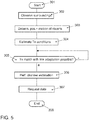
- Search process is illustrated with a flow chart for a corresponding program in Fig. 5 , The program starts in step 301.
- step 302 the corresponding step to step 202 of Fig. 4 is performed for the surroundings of the vehicle.
- Step 303 where position and motion of the objects is determined.
- step 304 the corresponding step to step 206 in Fig. 4 is performed.
- Step 305 to step 204 in Fig. 4 where a step of estimating the transmission conditions is performed. It may have been tested that this type of data could be delivered. If yes, the link adaptation will be executed.
- Step 306 to get a step by step estimation for sending back feedback information to the transmitter. This is done in the usual way by using DMRS symbols.
- the receiving station requests the DMRS mode which is appropriate for the transmission conditions determined in step 305, ie it sends a corresponding message to the transmitter.
- the receiver in step 307 should therefore use the DMRS mode should be used.
- the transmission time had that is, 305.
- Step 307 that is, there is a feedback loop from the receiver to the transmitter.
- the program ends in step 308.
- Special purpose processors may include application specific integrated circuits (ASICs), reduced instruction set computers (RISCs) and / or field programmable gate arrays (FPGAs).
- ASICs application specific integrated circuits
- RISCs reduced instruction set computers
- FPGAs field programmable gate arrays
- the proposed method and apparatus is implemented as a combination of hardware and software.
- the software is implemented as an application program tangibly embodied on a program storage device.
- the application program may be uploaded to, and executed by, a machine including any suitable architecture.
- the machine is running as one or more central processing units (CPU), a random access memory (RAM), and input / output (I / O) interface (s).
- CPU central processing units
- RAM random access memory
- I / O input / output
- the computer platform also includes an operating system and microinstruction code.
- various other peripheral devices may be connected to the computer platform Such as an additional data storage device and a printing device.
- the elements shown in the figures may be implemented in various forms of hardware, software or combinations thereof. Preferably, these elements are implemented in a one-or-more-general manner in a general-purpose device, which may include a processor, memory and input / output interfaces.
- a general-purpose device which may include a processor, memory and input / output interfaces.
- the phrase "coupled" is defined to mean directly connected to or through one or more intermediate components. Search intermediate components may include both hardware and software based components.
Landscapes
- Engineering & Computer Science (AREA)
- Computer Networks & Wireless Communication (AREA)
- Signal Processing (AREA)
- Quality & Reliability (AREA)
- Physics & Mathematics (AREA)
- General Physics & Mathematics (AREA)
- Multimedia (AREA)
- Chemical & Material Sciences (AREA)
- Analytical Chemistry (AREA)
- Traffic Control Systems (AREA)
- Mobile Radio Communication Systems (AREA)
Abstract
Description
- The disclosure relates to an improvement in the vehicle-to-vehicle communication V2V. More particularly it relates to an improvement for exchanging messages in the field of autonomous or cooperative driving. The disclosure further relates to a corresponding control unit, and a vehicle being equipped with such control unit as well as a corresponding computer program.
- Autonomous driving (sometimes referred to as automatic driving, automated driving or piloted driving) is the movement of vehicles, mobile robots and driverless transport systems which are largely autonomous. There are different degrees of autonomous driving. In this case, autonomous driving is also spoken at certain levels even if a driver is still present in the vehicle, who possibly only takes over the monitoring of the automatic driving operation. In Europe, the various transport ministries (in Germany, the Federal Institute for Road Systems (Bundesanstalt fur Straßenwesen) was involved) worked together and defined the following autonomous stages.
- Level 0: "Driver only", the driver drives himself, steers, gives gas, brakes, etc...
- Level 1: Certain assistance systems help with vehicle operation (including a cruise control system - Automatic Cruise Control ACC).
- Level 2: Partial automation. Therein, automatic parking, tracking function, general longitudinal guidance, acceleration, deceleration, etc. are taken over by the assistance systems (including collision avoidance).
- Level 3: High automation. The driver does not have to monitor the system continuously. The vehicle independently performs functions such as the triggering of the turn signal, lane change and tracking. The driver can turn to other things, but if requested, the system is requested to take over the lead within a pre-warning period. This form of autonomy is technically feasible on motorways. Legislators are working to allow Level 3 vehicles. The legal framework has already been created.
- Level 4: Full automation. The guidance of the vehicle is permanently adopted by the system. If the system is no longer able to handle the tasks, the driver can be asked to take the lead.
- Level 5: No driver required. Apart from setting the target and starting the system, no human intervention is required.
- Future cooperative driving applications are envisioned to significantly improve efficiency and comfort of automated driving. Increase in cooperation between vehicles pose specific requirements on communication system and the way messages are exchanged among cooperating vehicles.
- Usually any vehicular application inherently assumes an error-prone communication channel and dedicates the task of error minimization to lower layers of the ISO/OSI communication model.
- Nevertheless, the link-layer performance at any specific time highly depends on the actual communication channel properties which in V2V communications are highly non-stationary. The non-stationarity of the channel means that its statistical properties, including parameters which define a minimum satisfactory application performance vary over time and space and is different for each transmitter-receiver link. On one side, this results in the fact that in most of the cases the performance of the V2V communication link is underestimated but it may also happen, that the performance of the communication link at some time t might be well below the expected tolerable minimum. For both situations a result is that in many cases the overall efficiency of the communication process and hence also the application stability and functional safety in V2V communications remain below acceptable level. As a consequence, many potentially valued added and safety cooperative functions remain not implemented in existing V2V communications.
- There are two basic communication types used for functional interaction between autonomous/cooperative vehicles: point-to-point or unicast and point-to-multipoint or multicast and broadcast. As an example from the first class, such functions as a unicast acknowledgement message about a new group velocity while driving in the platoon can be mentioned. One possible application from the second class is a broadcast alarm message to inform neighboring vehicles about a detected potential for a collision. In both examples, the loss of the message results in undesirable or even dramatic negative effects for the vehicles involved in cooperation.
- At the moment, existing approaches to overcome the potential negative link mismatch can be classified into fast and slow link-adaptation methods.
- The "fast" algorithms, such as various types of the hybrid automatic repeat request technique HARQ usually rely on an opportunistic attempt of error reduction via an increase in redundancy and repetition of transmitted parity bits. Since the main goal is to achieve an improvement in a very short time, this approach conducts data retransmission in an opportunistic manner without taking into consideration the instant knowledge about actual link properties. Besides an inefficient channel use due to retransmission of data or parity bit information, such methods fail to bring benefit if the actual link condition cannot be sufficiently improved by the simple increase in redundancy. In addition, this approach will not be able to recognize such an unfavorable link state and will attempt even more unsuccessful retransmissions until the maximum number of retransmissions is reached. Such an activity would result in an even further reduction of the end-to-end link efficiency and in an increased application delay. Both of these potential negative impacts are highly undesirable for various mission critical V2V cooperative applications.
- On the contrary to the "fast", the so-called "slow" link-adaptation algorithms estimate the actual link quality and take this information into consideration. Nevertheless, since link estimation and adaptation takes time, their reaction takes time and they are not always very efficient in highly varying V2V channels. In addition, such algorithms require feedback from the communicating partners, which is not possible in the case of data broadcast without any feedback messages.
- An illustrative example of the possible problem in dynamic V2V cooperative communication for the broadcast case is an impact of time and space varying channel on the received broadcast message by the vehicles involved in cooperative collision avoidance maneuver. Here, due to differences in relative distances and velocities between the sender and all receiving vehicles, the corresponding error rate for each link will be significantly different from each other. Some vehicles may be able to receive the notification of collision alarm without any packed loss whereas other may not receive this notification even after multiple retransmissions. The absence of function-relevant information at some vehicles which are directly involved in the collision avoidance process may even result in a complete failure of the collision avoidance application.
- An illustrative example of the possible problem in dynamic V2V cooperative communication for the unicast case is the action of the emergency breaking in the cooperative platoon. Here the platoon leader needs a unicast confirmation from each platoon vehicle about its ability to reduce the current velocity to the requested by the platoon leader level. If at the time of unicast transmission the channel quality is being affected by the high Doppler spread components or by a strong specular reflection with very high Doppler shift from the passing by vehicle or a traffic sign in the vicinity, the unicast message may be lost and the platoon leader will require additional retransmission. Such retransmission may result in an application delay similarly to the described above manner, which in turn may limit such performance parameters of the high density platooning as a minimum distance between platoon members.
-
DE 10 2015 207 977 A1 describes a method for determining relevancy information which represents the importance of that piece of information in terms of traffic safety in a cooperative driving scenario. This solution offers increased flexibility in terms of the information to be transmitted in the event of a communication channel overload. The solution comprises acquisition of an object property of a first road participant and a second road participant. Further it comprises to determine the relevancy of the object property of the second road participant with regard to the object property of the first road participant. Then the solution comprises a step of selecting and transferring an object property for data communication to other road participants dependent on the relevancy information. - For the cooperative or autonomous driving, the exchange of certain messages of the vehicles among each other is very important. Such information included in messages may be position information, surroundings information, trajectory information, warning information, control information and more.
FromUS 2017/0041760 A1 a method for adapting at least one parameter of a communication system is known, wherein at least one subscriber is mobile, in which case a current position of the mobile subscriber is determined at a time and a channel quality for a future time is estimated on the basis of the current position using an environmental model, wherein at least one parameter is changed at the future time on the basis of the estimation. Also disclosed is a corresponding apparatus. Such a parameter is, for example, the transmission power, modulation type or modulation alphabet which indicates how many different symbols can be transmitted. A further example of a parameter is the information rate (also called code rate), for example. Another parameter may be, for example, the adjustment of antenna diversity system. These parameters influence the data rate, latency and reliability of the transmission. - The inventors identified different problems with these approaches described above. Since link adaptation takes time, these techniques applied to current transmission conditions are not always very efficient in highly varying V2V channels. The conditions may be obsolete before link adaptation has been performed. In addition, such algorithms require feedback from the communicating partners, which is not possible in the case of data broadcast without any feedback messages.
One challenge with these approaches is that they require extensive message exchange among partners within a very short time over an error prone communication network. - There is therefore a need for an improved approach for a data communication system which avoids the above mentioned disadvantages. This corresponds to the problem of the invention.
- This object is achieved by a method for data communication between at least two participants of a wireless communication system according to claim 1, a control unit according to claim 13, a vehicle according to claim 14 and a computer program according to claim 15. The dependent claims include advantageous further developments and improvements of the invention as described below.
The method for data communication between communication participants is based on the idea of trying to adapt the actual communication to basic channel properties via methods of the so-called sensor-based predicted communication technique. More in particular, the method for data communication comprises the steps of observing the surroundings of the transmitting participant, determining the positon and motion of the communication participants, and estimating the transmission conditions at a later point in time. The solution further includes a step of classifying the data ready for data transmission in different categories, said categories determining susceptibility of said data to transmission errors. With such a step it becomes evident which sort of data could be transmitted under good transmission conditions only and which sort of data could also be transmitted under rough transmission conditions and the transmission station can plan the transmission of data in different categories. Furthermore, the proposal comprises the steps of selecting based on said categories data for data transmission at a given point in time for which the transmission conditions have been estimated such that the data to be transmitted is in a category fitting to the estimated transmission conditions, and transmitting the selected data. This means in one example that the data which is classified in the category that it is very susceptible to transmission errors will not be transmitted at transmission times where the channel estimation predicts rough transmission conditions. The used term category does not necessarily mean the strict mapping between the message classes and the channel conditions but rather reflects the dependency between the data requirements and the predicted channel conditions. - The main advantage of the proposed approach is, that it can increase the stability of existing and future mission critical cooperative applications and is based on already available sensor data in the vehicle. Since error-prone transmissions are shifted to time slots where stable transmission conditions exist, falsified transmissions are avoided and that means retransmissions are avoided which subjectively improves the performance of the communication system. In consequence, the application which relies on the communication system as proposed works with greater stability/efficiency. In case of safety relevant applications such as cooperative or autonomous driving, the safety requirements can better be fulfilled.
- The solution is suitable to both main types of V2V message exchanges - acknowledged unicast communication mode and non-acknowledged broadcast communication mode. Another advantage is that it can be applied independently or combined with existing approaches used to increase the end-to-end application reliability.
- In one embodiment it is advantageous that the data ready for transmission is organized in the form of relations between a data-ready-for-transmission and the corresponding desired communication link quality, which can be dynamically or in a form of a look-up table listing the different categories of data which is stored in the transmit buffer of the transmitting station.
- In one embodiment it is advantageous that the step of estimating the transmission conditions comprises a step of estimating whether the receiving participant is in line of sight to the transmitting participant, obstructed line of sight or in non-line of sight to the transmitting participant. Since the position and motion of the communication participants is determined anyhow, this information can easily be determined in the transmitting participant. The information helps to increase estimation of the transmission conditions.
- In an enhanced embodiment the step of estimating the transmission conditions comprises at least one of the steps of estimating the relative velocity between at least two participants, estimating at least one of the Doppler frequency shift, delay spread, the power relation of scattered signal reflections from objects in the surroundings of the transmitting participant, estimating the signal travel time for at least the line of sight transmissions between at least two participants and optionally for the relevant signal reflections reaching the receiving participant. Certain techniques of link adaptation rely on the estimated information in this enhanced embodiment.
- It is further advantageous if in another embodiment the method further comprises a step of checking if the transmission conditions could be improved by link adaptation at the transmitting station. If the link adaptation technique is exhausted and there is no further option to increase robustness of the channel to interferences, then corresponding consequences could be taken.
- In a plurality of further embodiments the step of link adaptation at the transmitting participant comprises at least one of the techniques hybrid automatic repeat request HARQ, transmit power control, modulation type adaptation, puncturing and antenna diversity, such as multiple input single output MISO and multiple input multiple output MIMO processing at the transmitting station.
- In a still further embodiment, the step of link adaptation comprises a step of checking if the transmission conditions could be improved by link adaptation at the receiving station.
- For this embodiment it is advantageous if the step of link adaptation comprises at least one of the techniques Doppler compensation and antenna diversity, such as multiple input single output MISO and multiple input multiple output MIMO processing at the receiving station.
- It is further advantageous for the step of checking if the transmission conditions could be improved by link adaptation if it is determined if the data to be transmitted in a given category fits to the transmission conditions and if the transmission conditions are rougher than what is appropriate for the given data category, said data transmission is being postponed and optionally a data transmission with data in a category with lower susceptibility to rough transmission conditions is advanced. Such behavior is key for achieving the performance increase of the communication system as indicated above.
- Of course, in ideal case, the postponement of the data amounts the time where in the step of estimating the transmission conditions better transmission conditions are predicted.
- Most of the data in different categories comprise time critical data. Such data have certain time constraints. Therefore it is advantageous if in the step of categorizing data a latency of the data in the respective category is also assigned.
- In a specific embodiment the maximum allowed postponement of the data corresponds to the latency of the data in the given category. Thereby, the system can limit the postponement of data to the latency time which corresponds to the category. If by such postponement the transmission conditions required for the category cannot be reached, it is one strategy to discard such data from the buffer.
- It is also advantageous if in the step of categorizing data at least the categories unicast acknowledgement message and broadcast alarm message from the field of cooperative or autonomous driving are distinguished. Both data categories will be treated differently in the link adaptation technique.
Corresponding advantages are apparent for a control unit according to the proposal, a corresponding vehicle comprising a control unit according to the proposal and a computer program according to the proposal as claimed. - An exemplary embodiment of the invention is illustrated in the drawings and is explained in more detail below with reference to the figures.
- In the drawings:
- Fig. 1
- The principle of vehicle to vehicle communication via mobile radio communication;
- Fig. 2
- The principle of UWB distance measurements between the vehicles of a platoon;
- Fig. 3
- Shows a block diagram for a vehicle communication network with various vehicle electronics components;
- Fig. 4
- The flow chart of a computer program to be executed in a processing unit of a V2V transmitting participant; and
- Fig. 5
- The flow chart of a computer program to be executed in a processing unit of a V2V receiving participant.
- The present description illustrates the principles of the present disclosure. It will thus be appreciated that those skilled in the art will be able to devise various arrangements that, although not explicitly described or shown herein, embody the principles of the disclosure.
- All examples and conditional language recited herein are intended for educational purposes to aid the reader in understanding the principles of the disclosure and the concepts contributed by the inventor to furthering the art, and are to be construed as being without limitation to such specifically recited examples and conditions.
- Moreover, all statements herein reciting principles, aspects, and embodiments of the disclosure, as well as specific examples thereof, are intended to encompass both structural and functional equivalents thereof. Additionally, it is intended that such equivalents include both currently known equivalents as well as equivalents developed in the future, i.e., any elements developed that perform the same function, regardless of structure.
- Thus, for example, it will be appreciated by those skilled in the art that the diagrams presented herein represent conceptual views of illustrative circuitry embodying the principles of the disclosure.
- The functions of the various elements shown in the figures may be provided through the use of dedicated hardware as well as hardware capable of executing software in association with appropriate software. When provided by a processor, the functions may be provided by a single dedicated processor, by a single shared processor, or by a plurality of individual processors, some of which may be shared. Moreover, explicit use of the term "processor" or "controller" should not be construed to refer exclusively to hardware capable of executing software, and may implicitly include, without limitation, digital signal processor (DSP) hardware, read only memory (ROM) for storing software, random access memory (RAM), and nonvolatile storage.
- Other hardware, conventional and/or custom, may also be included. Similarly, any switches shown in the figures are conceptual only. Their function may be carried out through the operation of program logic, through dedicated logic, through the interaction of program control and dedicated logic, or even manually, the particular technique being selectable by the implementer as more specifically understood from the context.
- In the claims hereof, any element expressed as a means for performing a specified function is intended to encompass any way of performing that function including, for example, a) a combination of circuit elements that performs that function or b) software in any form, including, therefore, firmware, microcode or the like, combined with appropriate circuitry for executing that software to perform the function. The disclosure as defined by such claims resides in the fact that the functionalities provided by the various recited means are combined and brought together in the manner which the claims call for. It is thus regarded that any means that can provide those functionalities are equivalent to those shown herein.
-
FIG. 1 shows the principle of vehicle to vehicle communication V2V using mobile radio communication. The vehicles are labeled with reference number 30. The term vehicle is to be understood as a collective term for motor vehicles with an internal combustion engine or an electric motor, whether for bicycles with or without an electric motor or other vehicles powered by muscle, or for vehicles with one, two, four or more wheels. Whether for motorcycles, passenger cars, trucks, buses, agricultural vehicles or construction machines. The list is not exhaustive and includes other vehicle categories. - However, vehicle communication, in particular vehicle direct communication, is necessary for the fields of cooperative driving maneuvers or autonomous driving. Various systems for vehicle communication are developed. Examples include WLAN-based vehicle communication, also called "ad-hoc domain", and vehicle communication in the field of mobile radio networks. In the case of mobile radio-based technology, however, the base station has to transmit the messages from vehicle to vehicle. This is the area where communication takes place in the so-called "Infrastructure Domain". For the future mobile radio generation, the vehicle direct communication is also made possible. In LTE, according to Long Term Evolution, this variant is called LTE-V, in the case of the 5G initiative this variant is called D2D.
- The vehicles in
FIG. 1 are each equipped with a communication module 110, which serves as a transmitting and receiving unit for communication in a mobile radio network. The vehicle 30 here corresponds to a mobile radio network subscriber station because of the integrated communication module 110. All messages from the vehicles (uplink) and to the vehicles (downlink) are routed either via a base station 20 which serves a mobile radio cell or, in the case of direct vehicle communication (Sidelink), directly between the vehicles 30. If the vehicles 30 are within this mobile radio cell, they are registered or logged in at the base station 20. If they leave the mobile cell, they are handed over to the neighboring cell (handover) and accordingly logged off at the base station 20. The base station 20 also provides access to the Internet so that the vehicles 30 or all other mobile radio subscribers are supplied with Internet data in the mobile radio cell. For this purpose, the base station 20 is connected to the EPC 40 (Evolved Packet Core) via the so-called S1 interface. A central computer 50 is also accessible via the Internet 10 or another wide area network WAN. This may be located in a traffic control center to which e.g. some of the position data or trajectory information of the individual vehicles 30 may be reported for central surveillance or coordination. - Such mobile radio technologies are standardized and reference is made here to the corresponding specifications of mobile radio standards. As a modern example of a mobile radio standard, reference is made to the 3GPP initiative and the LTE standard (Long Term Evolution). Many of the related ETSI specifications are currently available in the version 14. The following is mentioned as an example from version 13: ETSI TS 136 213 V13.0.0 (2016-05); Evolved Universal Terrestrial Radio Access (E-UTRA); Physical layer procedures (3GPP TS 36.213 version 13.0.0 Release 13).
- LTE stands for high transmission rates and short response times. The increase in the transmission rate is achieved in LTE by better modulation methods, more flexible frequency usage and larger channel bandwidths. According to the specification, LTE currently has a transmission rate of more than 300 MBit / s in the downlink and 75 MBit / s in the uplink per 20 MHz band, mathematically and less overhead.
- The transmission speed of LTE is essentially dependent on the frequency range, the channel width, the distance to the base station 20 and the number of participants within the mobile radio cell. The more users use the bandwidth at the same time, the lower the transmission rate per subscriber.
- For the downlink the OFDMA technique (Orthogonal Frequency Division Multiple Access) is used. There, the known multi-carrier transmission technique OFDM (Orthogonal Frequency Division Multiplexing) is used, in which data symbols are modulated onto the individual carriers by QPSK (Quadrature Phase-Shift Keying) or QAM (Quadrature Amplitude Modulation). With OFDMA, the available frequency band is divided into many narrow bands (channels). The bandwidth is used flexibly to extract the utmost in transmission power from the frequencies.
- Special algorithms select the appropriate channels, taking into account the influences from the environment. In this case, preferably only the carriers are used for transmission, which are the cheapest for the user at its respective location.
- For the uplink the SC-FDMA technique is used (Single Carrier Frequency Division Multiple Access). This is a single-carrier access method which is very similar to OFDMA. SC-FDMA has lower power variations and makes simpler power amplifiers possible. This especially protects the battery of mobile devices.
- Sidelink communication also uses uplink communication resources.
-
Fig. 2 shows one prominent example of a cooperative driving maneuver which is called platooning. Platooning refers to intelligent convoy driving as an application, which is also known as "high density platooning". The distances between the vehicles of the convoy are e.g. trucks adapted to the traffic situation and regulated. The aim is to reduce the distance between the convoy vehicles as much as possible to reduce energy consumption. For this purpose, messages must be constantly exchanged between the convoy vehicles. - In
Fig. 2 , a vehicle convoy with four vehicles is shown. These are utility vehicles. Typically, these are trucks of appropriate length, which band together to cover a distance together to save energy and protect the environment. The platoon leader vehicle is designated PL, corresponding to "Platoon Leader". The following convoy vehicles are designated PV3 to PV1. All vehicles are equipped with a GNSS receiver corresponding to Global Navigation Satellite System. Examples of a GNSS receiver are a GPS-receiver corresponding to Global Positioning System, Galilei-, GLONASS- and Beidou-receiver. All vehicles of the platoon are equipped with on-board communication means for direct vehicle communication. Furthermore, it is shown that the vehicles are also equipped with UWB transceivers corresponding to ultra-wide-band transceivers. The vehicles are each equipped with 2 UWB transceivers, once at the front of the vehicle and second at the rear of the vehicle. The vehicles are also equipped with a platoon coordination unit. However, this feature is only activated on the platoon leader vehicle PL. - The use of UWB transceivers for distance measurements in the field of High Density Platooning is described in a master thesis of Eindhoven University of Technology. This master thesis with title "Ultra-wide Band for Vehicle Platooning" is dated August 2016 and the author is A. Srujan.
- The vehicles are also equipped with means for surroundings observation. The sensor system, which is used to capture the environmental objects is based on different measuring methods depending on the application. Widespread technologies are among others Radar corresponding to Radio Detection and Ranging, Lidar corresponding to Light detection and ranging, cameras 2D and 3D and ultrasonic sensors.
-
Fig. 3 shows the typical construction of an on-board network of a modern motor vehicle. Reference numeral 151 denotes an engine control unit. The reference numeral 152 corresponds to an ESC control unit corresponding to electronic stability control and the reference numeral 153 denotes a transmission control unit. Further control devices, such as a vehicle dynamics control unit, etc., may be provided in the motor vehicle. The networking of such control units, all of which are allocated to the category of the drive train, typically occurs with the CAN bus system (controller area network) 104. Since various sensors are installed in the motor vehicle and these are no longer only connected to individual control units, such sensor data are also distributed via the bus system 104 to the individual control devices. - Examples of sensors in the motor vehicle are wheel speed sensors, steering angle sensors, acceleration sensors, rotary data sensors, tire pressure sensors, distance sensors, knock sensors, air sensor sensors, etc. The various sensors with which the vehicle is equipped are designated by the reference number 161, 162, 163 in
Fig 3 .
However, the modern motor vehicle can also have further components such as video cameras 105, e.g. as a front camera, rear camera or side camera or as a driver monitoring camera, as well as a LIDAR (Light Detection and Ranging) or RADAR (Radio Detection and Ranging) device for the realization of a radar system or for implementing a distance warning or collision warning/avoidance device. Such systems are used more and more in vehicles for surroundings observation. There may be other systems in the vehicle, too such as ultra-sonic distance sensors for surroundings observation. The ultrasonic sensor typically is used for a short distance observation, e.g. 3 to 5m. The RADAR and LIDAR sensors could be used for scanning a range up to 250 m or 150 m and the cameras cover a range from 30 to 120 m. - A navigation system 120, which is also installed in the area of the cockpit, is often distinguished from this. The route, which is displayed on a map, can of course also be displayed on a display in the cockpit (not shown). Other components, such as a hands-free telephone system, may be present but are not shown in detail. Reference numeral 110 denotes an on-board unit. This on-board unit 110 corresponds to a communication module via which the vehicle can receive and transmit mobile data. Typically, this is a mobile radio communication module, e.g. according to the LTE standard. All these devices are assigned to the infotainment area. They are therefore networked via a bus system 102 designed for the special needs of this device category. A high speed CAN bus is one example, which could be applied.
- As a further example, an Ethernet-Bus 108 is shown which connects only the two components driver assistance controller 171 and UWB transceivers 172 and 173. As seen in
Fig. 2 , each vehicle is equipped with two UWB transceivers, one at the front and another one at the rear end. The Ethernet-Bus is a choice also for this communication bus 108 due to its higher bandwidth for data transport. One Ethernet-Bus adapted to the special needs of car communication is standardized in the IEEE 802.1Q specification. Moreover, a lot of information for surroundings observation may be received via V2V communication from other road participants. Particularly for those road participants not being in line of sight LOS to the observing vehicle it is very advantageous to receive the information about their position and motion via V2V communication.
For the purpose of transmitting the vehicle-relevant sensor data via the communication interface 110 to another vehicle or to a central computer 50, the gateway 140 is provided. - This is connected to the different bus systems 102, 104 and 108. The gateway 140 is adapted to convert the data it receives via the Ethernet-Bus 108 to be converted into the transmission format of the infotainment CAN-bus 102 so that it can be distributed in the packets specified there. For the forwarding of this data to the outside, i.e. to another motor vehicle or to central computer 50, the on-board unit 110 is equipped with the communication interface to receive these data packets and, in turn, to convert them into the transmission format of the correspondingly used mobile radio standard. As shown, the gateway 140 is connected as a central device to the busses 102, 104 as well as 108. It therefore takes all the necessary format conversions if data are to be exchanged between the different bus systems if required.
- Under the considered scenario of cooperative or autonomous driving the vehicles broadcast so-called Cooperative Awareness Messages CAM periodically such that they are aware which other vehicles are in the vicinity. Together with its own surroundings observation means, the observing vehicle is pretty well informed what happens in the near future and can estimate the transmission conditions pretty exact. It is noted, that not every information can be received via the on-board unit 110. There may be objects in the surroundings which are not equipped with V2V communications means. Such objects may include other vehicles, vulnerable road participants, obstacles and the like.
- A problem in surroundings observation and transmission condition estimation in vehicles is the influence of the relative movement between transmitting station and receiving station on the transmission conditions. In particular the Doppler effect causes a frequency shift at the receiving vehicle and is dependent on the frequency range of the transmission. There are solutions available to make the communication systems robust against the Doppler spread. One sophisticated solution for the LTE mobile communication system is described in
DE 10 2016 211 894 A1 . Here, the relative velocity between transmitting station and receiving station will be estimated and corresponding to the estimated velocity the number of DMRS symbols (demodulation reference symbol) will be adjusted for transmission of V2V messages. Those DMRS symbols serve as pilot reference symbols. With more DMRS symbols in the transmission frame channel estimation on the receiving side is more accurate such that the receiver can cope better with the Doppler spread. It is expressively referred to the cited reference in terms of the disclosure of the method for Doppler spread compensation in the present invention. In one embodiment both stations transmitting station and receiving station will estimate relative velocity and switch to the corresponding DMRS mode correspondingly. -
Fig. 4 shows the process being performed in the on-board communication unit 110 of a transmitting participant. This process is being performed e.g. in each of the platoon vehicles when they want to report a new distance measurement result to the platoon leader vehicle PL. In general it may also be performed when transmitting a CAM message, a cooperative maneuver message like a CACC message corresponding to Cooperative Adaptive Cruise Control or the like. There are further examples of such use cases like Vulnerable Road User message, Traffic Efficiency message or Teleoperated Driving message. These use cases are described in greater detail in the paper "Use Cases, Requirements, and Design Considerations for 5G V2X" of Mate Boban, Apostolos Kousaridas, Konstantinos Manolakis, Joseph Eichinger, Wen Xu of Huawei Technologies, German Research Center, 80992 Munich, Germany. - The method starts in step 201. In step 202 takes place a step of surroundings observation. On one hand this step includes object recognition by means of image processing algorithms applied to the images captured by the camera 105. On the other hand it includes evaluation of information having been collected by receiving CAM messages, cooperative sensing messages, vulnerable road user messages and traffic efficiency messages and the like.
- In step 203 it follows the determination of the position of the surrounding vehicles vulnerable road participants and other objects. Also in this step the motion of the surrounding vehicles, vulnerable road participants and other objects will be determined. Furthermore, for a planned unicast transmission it will be determined the relative velocity between the transmitting station and the receiving station.
- In the case of unicast transmission the transmitting vehicle knows that it communicates only with one partner. This allows the transmitting vehicle (based on sensor-based predictive communication algorithms) to roughly estimate the potential Doppler impact, delay spread and the power relation between all specular channel components which will affect the receiver performance. An Example for sensor-based Doppler prediction and compensation is the following: At the time of desired data transmission, the transmit vehicle based on the available knowledge from its own sensors and the information in cooperative awareness messages evaluates whether the receiving vehicle is in the line-of-sight (LOS), obstructed LOS (oLOS), or in non-LOS (LOS) condition. Then the relative velocity to the communicating partner and the presence of strong specular reflections such as from other vehicles, e.g. trucks in the vicinity and from the presence of large traffic signs is calculated. Note, that the position and motion of the vehicles is regularly exchanged among road participants, e.g. broadcasted in CAM messages. All this is performed in step 203.
- Then based on the relative and absolute velocity levels, LOS/oLOS/nLOS conditions and the presence of strong specular reflectors, the potential negative impacts on the link performance, such as Doppler impact on the communication process is estimated for the receiving vehicle in step 204. This includes the signal travel time calculation for the LOS transmission path and all relevant specular transmission paths based on the known distances to the receiving vehicle and to the specular reflectors which could potentially produce strong specular reflections.
- An illustrative example of the possible problem in dynamic V2V cooperative communication for the unicast case is the action of the emergency breaking in the cooperative high density platooning. Here the platoon leader PL needs a unicast confirmation from each platoon vehicle PV1 to PV3 about its ability to reduce the current velocity to the requested by the platoon leader PL. If at the time of unicast transmission the channel quality is being affected by high Doppler spread components or by a strong specular reflection with very high Doppler shift from the passing by vehicle or a traffic sign in the vicinity, the unicast message may be lost and the platoon leader PL will require additional retransmission. Such retransmission may result in an application delay similarly to the described above manner, which in turn may limit such performance parameters of the high density platooning as a minimum distance between platoon members.
- After the transmission conditions were estimated, the transmitting vehicle in step 205 selects the appropriate data from the transmit buffer in the on-board unit 110. This selection step takes the result from the transmission condition estimation step 204 and uses it as an index for a look-up table to find out which category of data it may select from the transmit buffer. This is because different data may have different susceptibility to transmission errors and different end-to-end latency. In the reference mentioned above from M. Boban et al. an example of different categories of data is presented in table 1. Since the transmission conditions are estimated for a period in the future, too the transmitting station can plan which category of data will be transmitted at what time. When no data is found in the transmit buffer in a category that is susceptible enough against the amount of transmission errors under the estimated transmission conditions, data from the category which fits best to the estimated transmission conditions are selected. In step 206 it follows a step in which it will be checked whether an available equalization, encoding and link adaptation strategy is capable to bring improvement. The data prepared for transmission will be organized in said look-up table with entries for the End-To-End Latency, Reliability corresponding to Error Proneness and required Data Rate. Table 1 below presents an excerpt from the table in the cited reference of M. Boban et al.
Table 1 Use Case Type End-to-End Latency Reliability Data Rate per veh. (kbps) Cooperative Awareness 100ms-1sec 90-95% 5-96 Cooperative Sensing 3ms-1sec >95% 5-25000 Cooperative Maneuver <3ms-100ms >99% 10-5000 Vulnerable Road User 100ms-1sec 95% 5-10 Traffic Efficiency >1sec <90% 10-2000 Teleoperated Driving 5-20ms >99% >25000 - In an advanced embodiment the table may include further categories of data. It may include particular categories for certain sensor types. E.g. Audio or video data may be less susceptible to transmission errors since there are a plurality of methods existing for error concealment like interpolation techniques. While the table lists the reliability as one search criterion, a tolerance to an error rate may be used as one alternative. The corresponding bit error rate BER values would then be entered in the table.
- For more detailed explanation of the sensor-based predictive communication algorithms it is referred to the parallel patent application of the applicant with reference number
DE 10 2015 214 968 A1 . Typical methodologies of link adaptation are reduction of the code rate, change to a different modulation type, e.g. from 128 QAM to 64 QAM to 32 QAM to 16 QAM to 8 PSK to QPSK to BPSK, puncturing and antenna diversity processing. The effect of this is that the data rate is reduced step by step but the reliability is increased step by step also. - If due to severe channel conditions no sufficient (the term "sufficient" means the acceptable performance for the given V2V application) improvement is expected, the transmission is being postponed up to the time in the future where the transmission conditions are predicted to be sufficient for such data within the allowed end-to-end latency by the application. The program then loops back to step 205.
- If the sufficient improvement is expected, the vehicle reconfigures the transmit parameters to minimize the potential negative impact of the channel. One possible example is compensation of the LOS Doppler shift due to high relative velocity between communicating vehicles. Here, the combination of predictive compensation at transmitter and receiver is also possible: e.g. then the receiving vehicle analyzes if any further improvement via sensor-based predictive communication is possible at the transmitter and applies post-equalization of the received signal. One possible example is to conduct a Doppler shift compensation of the strong specular signal component.
- Another example is to provide a frequency compensation shift of the group of Doppler spread spectral components, if it was detected at the receiver that the Doppler spread due to surrounding environment has non symmetrical distribution (this is usually the case in V2V communications).
The data will finally be transmitted in step 207. - For the data that has been postponed in step 206, it will be checked in step 208 if such data in the transmit buffer violates the required end-to-end latency. If yes, it will be deleted from the transmit buffer in step 209. If not, the program directly ends in step 210 without performing step 209.
- In an alternative embodiment, the data will not just be postponed but it will be processed before being transmitted, too. A postponement may be included in this step, too. One example for this solution is the transmission of sensor data for the use case of cooperative sensing. If the transmission of the sensor raw data is not possible, due to the transmission conditions, such data will be processed before transmission. By this processing step the amount of data to be transmitted may be reduced. On the other hand the data may be secured by using additional error protecting or error correcting codes.
- In the typical multicast or broadcast communication the transmitted message is intended to many communicating partners in the vicinity. This leads to the problem that some of the receiving partners may be not known to the transmitting vehicle. Even if the information about other communication partners is available at the transmitter, it will still be a very challenging task to adapt the transmit signal to all possible receiving vehicles simultaneously, since the range of such adaptation is determined by the physical properties of the transmission channel (e.g. number of transmit antennas, size of the precoding matrix, etc.). Due to this, the typical sensor- based predictive communication technique may not be possible at the transmitter for transmissions in multicast or broadcast communication modes.
- An illustrative example of the possible problem in dynamic V2V cooperative communication for the broadcast case is an impact of time and space varying channel on the received broadcast message by the vehicles involved in cooperative collision avoidance maneuver. Here, due to differences in relative distances and velocities between the sender and all receiving vehicles, the corresponding error rate for each link will be significantly different from each other. Some vehicles may be able to receive the notification of collision alarm without any data packet loss whereas others may not receive this notification even after multiple retransmissions. The absence of function-relevant information at some vehicles which are directly involved in the collision avoidance process may even result in a complete failure of the collision avoidance application. Nevertheless, it is one approach to use the same process as shown in
Fig. 4 also for the broadcast transmission mode. Of course, the step 204 of estimating the transmission conditions is much more demanding since the transmission conditions for multiple links need to be estimated. The worst conditions may be taken for the further process then. - In another embodiment, the predictive Doppler compensation will be done at the receiving participant, since for the receiving participant the multicast transmission is seen as a unicast link. Then in this case, the predictive communication has to be conducted at the receiver, i.e. the receiver needs to inform the transmitting station when the corresponding data should be send. Such process is depicted with a flow chart for a corresponding program in
Fig. 5 . The program starts in step 301. In step 302 the corresponding step to step 202 ofFig. 4 is performed for observing the surroundings of the vehicle. Step 303 corresponds to step 203 where position and motion of the objects is determined. In step 304 the corresponding step to step 206 inFig. 4 is performed. Step 305 corresponds to step 204 inFig. 4 where a step of estimating the transmission conditions is performed. For a selected category of data the receiving station awaits from a transmitting station it will be checked if with link adaptation the estimated transmission conditions could be improved such that such type of data could be delivered. If yes, the link adaptation will be executed. This concerns e.g. the selection of the DMRS mode as explained above in one example. The receiver needs to request this link adaptation at the transmitter. Step 306 corresponds to a step of channel estimation for sending back such feedback information to the transmitter. This is executed in the usual manner by utilizing said DMRS symbols of the current DMRS mode. In step 307 the receiving station requests the DMRS mode which is appropriate for the transmission conditions determined in step 305, i.e. it sends a corresponding message to the transmitter. In an enhanced embodiment the receiver in step 307 also informs the transmitter at what time such data should be sent and such DMRS mode should be used. The transmission time had also been determined in the transmission condition estimation step 305. Step 307 therefore corresponds to a feedback loop from the receiver to the transmitter. The program ends in step 308. - It is to be understood that the proposed method and apparatus may be implemented in various forms of hardware, software, firmware, special purpose processors, or a combination thereof. Special purpose processors may include application specific integrated circuits (ASICs), reduced instruction set computers (RISCs) and/or field programmable gate arrays (FPGAs). Preferably, the proposed method and apparatus is implemented as a combination of hardware and software. Moreover, the software is preferably implemented as an application program tangibly embodied on a program storage device. The application program may be uploaded to, and executed by, a machine comprising any suitable architecture. Preferably, the machine is implemented on a computer platform having hardware such as one or more central processing units (CPU), a random access memory (RAM), and input/output (I/O) interface(s). The computer platform also includes an operating system and microinstruction code. The various processes and functions described herein may either be part of the microinstruction code or part of the application program (or a combination thereof), which is executed via the operating system. In addition, various other peripheral devices may be connected to the computer platform such as an additional data storage device and a printing device.
- It should be understood that the elements shown in the figures may be implemented in various forms of hardware, software or combinations thereof. Preferably, these elements are implemented in a combination of hardware and software on one or more appropriately programmed general-purpose devices, which may include a processor, memory and input/output interfaces. Herein, the phrase "coupled" is defined to mean directly connected to or indirectly connected with through one or more intermediate components. Such intermediate components may include both hardware and software based components.
- It is to be further understood that, because some of the constituent system components and method steps depicted in the accompanying figures are preferably implemented in software, the actual connections between the system components (or the process steps) may differ depending upon the manner in which the proposed method and apparatus is programmed. Given the teachings herein, one of ordinary skill in the related art will be able to contemplate these and similar implementations or configurations of the proposed method and apparatus.
- The disclosure is not restricted to the exemplary embodiments described here. There is scope for many different adaptations and developments which are also considered to belong to the disclosure.
-
- 10
- Internet
- 20
- Base Station
- 30
- Vehicle
- 40
- Evolved Packet Core EPC
- 50
- Traffic Control Center Computer
- 100
- Block Diagram Car Communication
- 102
- High-speed CAN-Bus
- 105
- Camera
- 104
- CAN-Bus
- 108
- Ethernet-Bus
- 110
- On-Board Unit
- 120
- Navigation System
- 140
- Gateway
- 151
- Engine Control Unit
- 152
- ESC-Control Unit
- 153
- Transmission Control Unit
- 161
- Sensor 1
- 162
- Sensor 2
- 163
- Sensor 3
- 171
- Driver Assist Control Unit
- 172
- UWB Transceiver
- 173
- UWB Transceiver
- 1712
- UWB Ranging Scheduling Unit
- 201 - 210
- Transmitter Program Steps
- 301 - 308
- Receiver Program Steps
Claims (16)
- Method for data communication between at least two participants (PL, PV1-PV3) of a wireless communication system, comprising the steps, observing the surroundings of the transmitting participant (202), determining the position and motion of the participants (203), estimating the transmission conditions for a later point in time (204), characterized in that the data ready for data communication is classified in different categories, said categories determining susceptibility of said data to transmission errors, selecting data for data transmission at a given point in time for which the transmission conditions have been estimated based on said categories (205) such that the data to be transmitted is in a category fitting to the estimated transmission conditions, and transmitting the selected data (207).
- Method according to claim 1, wherein the step of estimating the transmission conditions (204) comprises a step of estimating whether the receiving participant is in line of sight LOS to the transmitting participant, obstructed line of sight oLOS or in non-line of sight nLOS to the transmitting participant.
- Method according to claim 1 or claim 2, wherein the step of estimating the transmission conditions (204) comprises at least one of the steps of estimating the relative velocity between at least two participants, estimating at least one of the Doppler frequency shift, delay spread, the power relation of signal reflections from objects in the surroundings of the transmitting participant and estimating the signal travel time for at least the line of sight transmissions between at least two participants and optionally for the relevant signal reflections reaching the receiving participant.
- Method according to one of the previous claims, wherein the data ready for transmission is organized in a look-up table in a transmit buffer, said look-up table listing the data ready for transmission in said categories.
- Method according to one of the previous claims, further comprising a step of checking (206) if the transmission conditions could be improved by link adaptation at the transmitting station.
- Method according to claim 5, wherein the step of link adaptation (206) comprises at least one of the techniques hybrid automatic repeat request HARQ, transmit power control, modulation type adaptation, puncturing and antenna diversity processing, such as multiple input single output MISO and multiple input multiple output MIMO processing at the transmitting station.
- Method according to one of the previous claims, further comprising a step of checking (305) if the transmission conditions could be improved by link adaptation at the receiving station.
- Method according to claim 7, wherein the step of link adaptation (305) comprises at least one of the techniques Doppler compensation and antenna diversity processing, such as multiple input single output MISO and multiple input multiple output MIMO processing at the receiving station, wherein for the technique of Doppler compensation the receiving station sends a feedback message to the transmitting station with which the transmitting station is informed about the type of link adaptation to be performed and optionally the time at which this link adaptation is to be performed.
- Method according to one of the previous claims, wherein for categorizing data at least the categories unicast acknowledgement message and broadcast alarm message from the field of cooperative or autonomous driving are distinguished.
- Method according to one of the previous claims, wherein for the step of checking (206) if the transmission conditions could be improved by link adaptation it is determined if the data to be transmitted in a given category fits to the transmission conditions and if the transmission conditions are rougher than what is appropriate for the given category, said data transmission is being postponed and wherein optionally a data transmission with data in a category with lower susceptibility to rough transmission conditions is advanced.
- Method according to one of the previous claims, wherein the postponement of the data amounts the time where in the step of estimating the transmission conditions better transmission conditions are predicted.
- Method according to claim 11, wherein for categorizing data the maximum allowed latency of the data in the respective category is also assigned.
- Method according to one of the previous claims, wherein in the step of checking (206) if the transmission conditions could be improved a maximum allowed postponement of the data corresponds to the latency of the data in the given category.
- Control unit, characterized in that, the control unit (171) is adapted to perform the steps of one of the previous claims.
- Vehicle, characterized in that, the vehicle (30) is equipped with a control unit (171) according to claim 14.
- Computer program, characterized in that, the computer program comprises program steps, which when run in a computer carry out a method according to one of the claims 1 to 13.
Priority Applications (4)
| Application Number | Priority Date | Filing Date | Title |
|---|---|---|---|
| EP18155554.1A EP3525374B1 (de) | 2018-02-07 | 2018-02-07 | Verfahren zur datenkommunikation zwischen mindestens zwei teilnehmern in einem drahtlos-kommunikations-system, korrespondierende kontrolleinheit, fahrzeug mit kontrolleinheit, sowie computer programm |
| US16/258,914 US10790927B2 (en) | 2018-02-07 | 2019-01-28 | Method for data communication between at least two participants of a wireless communication system, corresponding control unit and transportation vehicle equipped with a control unit and a computer program |
| KR1020190014543A KR102170581B1 (ko) | 2018-02-07 | 2019-02-07 | 무선 통신 시스템의 적어도 두 명의 참가자들 간의 데이터 통신 방법, 대응하는 제어 유닛, 제어 유닛이 장착된 차량 및 컴퓨터 프로그램 |
| CN201910110039.1A CN110120849B (zh) | 2018-02-07 | 2019-02-11 | 在无线通信系统的至少两个参与者之间数据通信的方法 |
Applications Claiming Priority (1)
| Application Number | Priority Date | Filing Date | Title |
|---|---|---|---|
| EP18155554.1A EP3525374B1 (de) | 2018-02-07 | 2018-02-07 | Verfahren zur datenkommunikation zwischen mindestens zwei teilnehmern in einem drahtlos-kommunikations-system, korrespondierende kontrolleinheit, fahrzeug mit kontrolleinheit, sowie computer programm |
Publications (2)
| Publication Number | Publication Date |
|---|---|
| EP3525374A1 true EP3525374A1 (de) | 2019-08-14 |
| EP3525374B1 EP3525374B1 (de) | 2021-10-06 |
Family
ID=61188622
Family Applications (1)
| Application Number | Title | Priority Date | Filing Date |
|---|---|---|---|
| EP18155554.1A Active EP3525374B1 (de) | 2018-02-07 | 2018-02-07 | Verfahren zur datenkommunikation zwischen mindestens zwei teilnehmern in einem drahtlos-kommunikations-system, korrespondierende kontrolleinheit, fahrzeug mit kontrolleinheit, sowie computer programm |
Country Status (4)
| Country | Link |
|---|---|
| US (1) | US10790927B2 (de) |
| EP (1) | EP3525374B1 (de) |
| KR (1) | KR102170581B1 (de) |
| CN (1) | CN110120849B (de) |
Cited By (1)
| Publication number | Priority date | Publication date | Assignee | Title |
|---|---|---|---|---|
| EP3910829A1 (de) * | 2020-05-12 | 2021-11-17 | Volkswagen Aktiengesellschaft | Fahrzeug, infrastruktur, sendeempfänger, vorrichtung, verfahren und computerprogramms zur bestimmung einer konfiguration einer physikalischen schicht für eine funkverbindung |
Families Citing this family (18)
| Publication number | Priority date | Publication date | Assignee | Title |
|---|---|---|---|---|
| US20190373419A1 (en) * | 2018-05-30 | 2019-12-05 | Peloton Technology, Inc. | Voice communications for platooning vehicles |
| EP3700108B1 (de) | 2019-02-20 | 2023-08-09 | Volkswagen Aktiengesellschaft | Verfahren zum unterstützen einer ersten mobilstation zum vorhersagen der kanalqualität für eine geplante dezentrale drahtlose kommunikation zu einer kommunikationspartnerstation und mobilstation |
| KR102610741B1 (ko) * | 2018-11-15 | 2023-12-08 | 현대자동차주식회사 | 차량의 군집주행 제어 장치 및 그 방법 |
| ES2894073T3 (es) * | 2019-07-04 | 2022-02-11 | Kapsch Trafficcom Ag | Método para la comunicación cifrada en una red Ad-hoc |
| US10873840B1 (en) * | 2019-07-30 | 2020-12-22 | Continental Teves Ag & Co. Ohg | Communication apparatus for vehicle-to-X communication, method and use |
| EP3869843B1 (de) * | 2020-02-19 | 2024-06-19 | Volkswagen Ag | Verfahren zum aufrufen einer ferngesteuerten fahrsitzung, vorrichtung zur durchführung der schritte des verfahrens, fahrzeug und computerprogramm |
| US11711680B2 (en) * | 2020-06-09 | 2023-07-25 | Qualcomm Incorporated | Vehicle-to-vehicle maneuver sharing and coordinating |
| DE102020209871A1 (de) * | 2020-08-05 | 2022-02-10 | Robert Bosch Gesellschaft mit beschränkter Haftung | Verfahren zur Sicherung einer Kommunikation zwischen einem ersten und einem zweiten Fahrzeug, Steuereinrichtung, Kommunikationsanordnung und Fahrzeuganordnung |
| DE102020210616A1 (de) * | 2020-08-20 | 2022-02-24 | Robert Bosch Gesellschaft mit beschränkter Haftung | Verfahren zur Kommunikation zwischen mindestens zwei hintereinanderfahrenden Fahrzeugen sowie Fahrzeug mit mindestens einer Kommunikationsvorrichtung |
| KR20220078804A (ko) * | 2020-12-04 | 2022-06-13 | 현대자동차주식회사 | 군집 주행 차량의 통신 시스템 |
| EP4017097A1 (de) * | 2020-12-17 | 2022-06-22 | Robert Bosch GmbH | Vorrichtung und verfahren zum betreiben eines drahtlosen kommunikationsnetzes |
| US11251888B1 (en) | 2020-12-18 | 2022-02-15 | Itron, Inc. | Preserving battery life in poor signal conditions using RF link analysis |
| US11638215B2 (en) * | 2020-12-18 | 2023-04-25 | Itron, Inc. | Techniques for preserving battery life in poor signal conditions using cellular protocol information |
| US11363599B1 (en) * | 2021-03-22 | 2022-06-14 | Qualcomm Incorporated | Interactive control of moving device speed and processing system operating frequency |
| CN113613201B (zh) * | 2021-08-02 | 2025-01-17 | 腾讯科技(深圳)有限公司 | 应用于车辆间的数据分享方法、装置、介质及电子设备 |
| US12193044B2 (en) | 2022-02-25 | 2025-01-07 | Toyota Motor Engineering & Manufacturing North America, Inc. | Resource selection for 5G NR V2X communications |
| CN116740915B (zh) * | 2023-06-21 | 2025-10-31 | 福州大学 | 一种公路圆曲线段慢车道内自动驾驶车队编队方法 |
| CN117407829B (zh) * | 2023-10-16 | 2024-04-19 | 创维互联(北京)新能源科技有限公司 | 基于深度学习的光伏组件健康度评估方法、系统和设备 |
Citations (4)
| Publication number | Priority date | Publication date | Assignee | Title |
|---|---|---|---|---|
| EP1494385A1 (de) * | 2003-06-30 | 2005-01-05 | Lucent Technologies Inc. | Verfahren und Vorrichtung zur Leistungsverbesserung der Ablaufsteuerungsleistung in drahtlosen Paketdatensystemen |
| DE102015207977A1 (de) | 2015-04-30 | 2016-11-03 | Bayerische Motoren Werke Aktiengesellschaft | Verfahren zur Übermittlung einer verkehrsrelevanten Information und kooperatives Fahrzeug |
| US20170041760A1 (en) | 2015-08-05 | 2017-02-09 | Volkswagen Ag | Method and device for adjustment of at least one parameter of a communication system |
| DE102016211894A1 (de) | 2016-03-18 | 2017-09-21 | Volkswagen Aktiengesellschaft | Verfahren zur Übertragung von Daten über einen Funkkanal, sowie Sendestation und Empfangsstation zur Verwendung bei dem Verfahren |
Family Cites Families (16)
| Publication number | Priority date | Publication date | Assignee | Title |
|---|---|---|---|---|
| US5726984A (en) * | 1989-01-31 | 1998-03-10 | Norand Corporation | Hierarchical data collection network supporting packetized voice communications among wireless terminals and telephones |
| US6976090B2 (en) * | 2000-04-20 | 2005-12-13 | Actona Technologies Ltd. | Differentiated content and application delivery via internet |
| KR101360350B1 (ko) | 2007-08-21 | 2014-02-10 | 재단법인서울대학교산학협력재단 | 도플러 주파수를 이용한 링크 적응화 시스템 및 그 방법 |
| US8301177B2 (en) | 2009-03-03 | 2012-10-30 | Intel Corporation | Efficient paging operation for femtocell deployment |
| US8682573B2 (en) * | 2010-08-20 | 2014-03-25 | Deere & Company | Method of initiating vehicle movement |
| US9135624B2 (en) * | 2010-09-23 | 2015-09-15 | Intelligent Mechatronic Systems Inc. | User-centric traffic enquiry and alert system |
| SG11201400963SA (en) * | 2012-02-08 | 2014-04-28 | Adept Technology Inc | Job management sytem for a fleet of autonomous mobile robots |
| US20130218445A1 (en) * | 2012-02-16 | 2013-08-22 | Intelligent Mechatronic Systems Inc. | Traffic portal enquiry and alert system |
| EP2901720B1 (de) * | 2012-09-25 | 2019-07-17 | Telefonaktiebolaget LM Ericsson (publ) | Nachrichtenübertragung zwischen fahrzeug-zu-fahrzeug kommunikationsfähigen vorrichtungen |
| CA3001385C (en) | 2014-10-15 | 2023-03-07 | Weihua ZHUANG | Method, system and apparatus for enabling vehicular communications |
| KR101621877B1 (ko) | 2015-01-20 | 2016-05-31 | 현대자동차주식회사 | 차량 데이터 수집 방법 및 장치 |
| US10278092B2 (en) * | 2015-08-13 | 2019-04-30 | Bae Systems Plc | Apparatus and method for communications management |
| DE102016106623A1 (de) | 2016-04-11 | 2017-10-12 | Bayerische Motoren Werke Aktiengesellschaft | Vorrichtungen, Verfahren und Computerprogramme für einen Basisstations-Sendeempfänger und einen mobilen Sendeempfänger |
| CN106332216B (zh) * | 2016-08-03 | 2019-09-03 | 成都之达科技有限公司 | 车辆间点对点通信方法 |
| CN107566235B (zh) * | 2017-09-28 | 2020-07-28 | 北京新能源汽车股份有限公司 | 一种报文数据传输方法、装置及电动汽车 |
| US10831636B2 (en) * | 2018-01-08 | 2020-11-10 | Waymo Llc | Software validation for autonomous vehicles |
-
2018
- 2018-02-07 EP EP18155554.1A patent/EP3525374B1/de active Active
-
2019
- 2019-01-28 US US16/258,914 patent/US10790927B2/en active Active
- 2019-02-07 KR KR1020190014543A patent/KR102170581B1/ko active Active
- 2019-02-11 CN CN201910110039.1A patent/CN110120849B/zh active Active
Patent Citations (6)
| Publication number | Priority date | Publication date | Assignee | Title |
|---|---|---|---|---|
| EP1494385A1 (de) * | 2003-06-30 | 2005-01-05 | Lucent Technologies Inc. | Verfahren und Vorrichtung zur Leistungsverbesserung der Ablaufsteuerungsleistung in drahtlosen Paketdatensystemen |
| DE102015207977A1 (de) | 2015-04-30 | 2016-11-03 | Bayerische Motoren Werke Aktiengesellschaft | Verfahren zur Übermittlung einer verkehrsrelevanten Information und kooperatives Fahrzeug |
| US20170041760A1 (en) | 2015-08-05 | 2017-02-09 | Volkswagen Ag | Method and device for adjustment of at least one parameter of a communication system |
| DE102015214968A1 (de) | 2015-08-05 | 2017-02-09 | Volkswagen Aktiengesellschaft | Verfahren und Vorrichtung zur Anpassung mindestens eines Parameters eines Kommunikationssystems |
| US9807566B2 (en) * | 2015-08-05 | 2017-10-31 | Volkswagen Ag | Method and device for adjustment of at least one parameter of a communication system |
| DE102016211894A1 (de) | 2016-03-18 | 2017-09-21 | Volkswagen Aktiengesellschaft | Verfahren zur Übertragung von Daten über einen Funkkanal, sowie Sendestation und Empfangsstation zur Verwendung bei dem Verfahren |
Non-Patent Citations (1)
| Title |
|---|
| BOBAN MATE ET AL: "Design aspects for 5G V2X physical layer", 2016 IEEE CONFERENCE ON STANDARDS FOR COMMUNICATIONS AND NETWORKING (CSCN), IEEE, 31 October 2016 (2016-10-31), pages 1 - 7, XP033026817, DOI: 10.1109/CSCN.2016.7785161 * |
Cited By (3)
| Publication number | Priority date | Publication date | Assignee | Title |
|---|---|---|---|---|
| EP3910829A1 (de) * | 2020-05-12 | 2021-11-17 | Volkswagen Aktiengesellschaft | Fahrzeug, infrastruktur, sendeempfänger, vorrichtung, verfahren und computerprogramms zur bestimmung einer konfiguration einer physikalischen schicht für eine funkverbindung |
| WO2021228558A1 (en) | 2020-05-12 | 2021-11-18 | Volkswagen Aktiengesellschaft | Vehicle, infrastructure, transceiver, apparatus, method and computer program for determining a physical layer configuration for a radio link |
| US12507083B2 (en) | 2020-05-12 | 2025-12-23 | Volkswagen Aktiengesellschaft | Vehicle, infrastructure, transceiver, apparatus, method and computer program for determining a physical layer configuration for a radio link |
Also Published As
| Publication number | Publication date |
|---|---|
| US20190245647A1 (en) | 2019-08-08 |
| KR20190095903A (ko) | 2019-08-16 |
| CN110120849A (zh) | 2019-08-13 |
| CN110120849B (zh) | 2022-05-03 |
| KR102170581B1 (ko) | 2020-10-27 |
| EP3525374B1 (de) | 2021-10-06 |
| US10790927B2 (en) | 2020-09-29 |
Similar Documents
| Publication | Publication Date | Title |
|---|---|---|
| US10790927B2 (en) | Method for data communication between at least two participants of a wireless communication system, corresponding control unit and transportation vehicle equipped with a control unit and a computer program | |
| KR102353558B1 (ko) | 통신 파트너 국, 이동국 및 차량에 대한 계획된 분산 무선 통신의 채널 품질을 예측하도록 제1 이동국을 지원하는 방법 | |
| KR102235198B1 (ko) | 차량군의 차량들 사이의 거리 측정을 수행하기 위한 방법 및 상기 방법에 사용하기 위한 차량 모듈 및 차량 | |
| US20200005650A1 (en) | Method of controlling platooning in autonomous driving system | |
| US12528466B2 (en) | Method for transmitting and receiving signal by vehicle in wireless communication system, and vehicle therefor | |
| US11700514B2 (en) | Method for a wireless communication from a first transportation vehicle to a road infrastructure station and apparatus for use in a transportation vehicle and adapted transportation vehicle | |
| US10916128B2 (en) | Method for data communication between at least two participants of a wireless communication system, corresponding control unit and transportation vehicle equipped with a control unit, and computer program | |
| US10271246B2 (en) | Method for transferring a mobile network subscriber station in a handover process in a mobile network, mobile network subscriber station, and mobile network management unit for use in the method and vehicle | |
| JP5089234B2 (ja) | 通信装置 | |
| KR20190106844A (ko) | 입력 신호 우선 순위에 따른 자율 주행 제어 방법 및 이를 이용한 자율 주행 시스템 | |
| JP6608973B2 (ja) | 移動無線ネットワークにおいてデータを一括取得するための方法ならびに当該方法において使用するためのデータ取得コンピュータおよび移動無線ネットワーク管理ユニット | |
| KR102419309B1 (ko) | 차량 대 차량 통신을 위한 방법 | |
| KR20220087481A (ko) | 무선 통신 시스템에서 차량, 단말 및 네트워크가 신호를 전송하는 방법 및 이를 위한 차량, 단말 및 네트워크 | |
| KR102537192B1 (ko) | 자율 주행 차량 및 그 제어 방법 | |
| US12021575B2 (en) | Method for predictively estimating the transmission conditions for a communication between two communication partners, device for carrying out the method steps of the method, vehicle and computer program | |
| EP4692833A1 (de) | Verfahren zur übertragung einer nachricht in einem drahtloskommunikationssystem durch ein netzwerk und vorrichtung dafür | |
| KR20250122214A (ko) | V2x 통신 시스템에서 전력 소모 절감 방법 및 장치 | |
| CN120642354A (zh) | 在无线通信系统中网络发送消息的方法及其设备 | |
| CN120642353A (zh) | 在无线通信系统中由终端发送消息的方法及其设备 |
Legal Events
| Date | Code | Title | Description |
|---|---|---|---|
| PUAI | Public reference made under article 153(3) epc to a published international application that has entered the european phase |
Free format text: ORIGINAL CODE: 0009012 |
|
| STAA | Information on the status of an ep patent application or granted ep patent |
Free format text: STATUS: THE APPLICATION HAS BEEN PUBLISHED |
|
| AK | Designated contracting states |
Kind code of ref document: A1 Designated state(s): AL AT BE BG CH CY CZ DE DK EE ES FI FR GB GR HR HU IE IS IT LI LT LU LV MC MK MT NL NO PL PT RO RS SE SI SK SM TR |
|
| AX | Request for extension of the european patent |
Extension state: BA ME |
|
| STAA | Information on the status of an ep patent application or granted ep patent |
Free format text: STATUS: REQUEST FOR EXAMINATION WAS MADE |
|
| 17P | Request for examination filed |
Effective date: 20200214 |
|
| RBV | Designated contracting states (corrected) |
Designated state(s): AL AT BE BG CH CY CZ DE DK EE ES FI FR GB GR HR HU IE IS IT LI LT LU LV MC MK MT NL NO PL PT RO RS SE SI SK SM TR |
|
| GRAP | Despatch of communication of intention to grant a patent |
Free format text: ORIGINAL CODE: EPIDOSNIGR1 |
|
| STAA | Information on the status of an ep patent application or granted ep patent |
Free format text: STATUS: GRANT OF PATENT IS INTENDED |
|
| INTG | Intention to grant announced |
Effective date: 20210602 |
|
| RIN1 | Information on inventor provided before grant (corrected) |
Inventor name: ALIEIEV, ROMAN Inventor name: JORNOD, GUILLAUME Inventor name: KWOCZEK, ANDREAS Inventor name: HEHN, THORSTEN |
|
| GRAS | Grant fee paid |
Free format text: ORIGINAL CODE: EPIDOSNIGR3 |
|
| GRAA | (expected) grant |
Free format text: ORIGINAL CODE: 0009210 |
|
| STAA | Information on the status of an ep patent application or granted ep patent |
Free format text: STATUS: THE PATENT HAS BEEN GRANTED |
|
| AK | Designated contracting states |
Kind code of ref document: B1 Designated state(s): AL AT BE BG CH CY CZ DE DK EE ES FI FR GB GR HR HU IE IS IT LI LT LU LV MC MK MT NL NO PL PT RO RS SE SI SK SM TR |
|
| REG | Reference to a national code |
Ref country code: GB Ref legal event code: FG4D Free format text: NOT ENGLISH |
|
| REG | Reference to a national code |
Ref country code: CH Ref legal event code: EP Ref country code: AT Ref legal event code: REF Ref document number: 1437117 Country of ref document: AT Kind code of ref document: T Effective date: 20211015 |
|
| REG | Reference to a national code |
Ref country code: IE Ref legal event code: FG4D |
|
| REG | Reference to a national code |
Ref country code: DE Ref legal event code: R096 Ref document number: 602018024480 Country of ref document: DE |
|
| REG | Reference to a national code |
Ref country code: LT Ref legal event code: MG9D |
|
| REG | Reference to a national code |
Ref country code: NL Ref legal event code: MP Effective date: 20211006 |
|
| REG | Reference to a national code |
Ref country code: AT Ref legal event code: MK05 Ref document number: 1437117 Country of ref document: AT Kind code of ref document: T Effective date: 20211006 |
|
| PG25 | Lapsed in a contracting state [announced via postgrant information from national office to epo] |
Ref country code: RS Free format text: LAPSE BECAUSE OF FAILURE TO SUBMIT A TRANSLATION OF THE DESCRIPTION OR TO PAY THE FEE WITHIN THE PRESCRIBED TIME-LIMIT Effective date: 20211006 Ref country code: LT Free format text: LAPSE BECAUSE OF FAILURE TO SUBMIT A TRANSLATION OF THE DESCRIPTION OR TO PAY THE FEE WITHIN THE PRESCRIBED TIME-LIMIT Effective date: 20211006 Ref country code: FI Free format text: LAPSE BECAUSE OF FAILURE TO SUBMIT A TRANSLATION OF THE DESCRIPTION OR TO PAY THE FEE WITHIN THE PRESCRIBED TIME-LIMIT Effective date: 20211006 Ref country code: BG Free format text: LAPSE BECAUSE OF FAILURE TO SUBMIT A TRANSLATION OF THE DESCRIPTION OR TO PAY THE FEE WITHIN THE PRESCRIBED TIME-LIMIT Effective date: 20220106 Ref country code: AT Free format text: LAPSE BECAUSE OF FAILURE TO SUBMIT A TRANSLATION OF THE DESCRIPTION OR TO PAY THE FEE WITHIN THE PRESCRIBED TIME-LIMIT Effective date: 20211006 |
|
| PG25 | Lapsed in a contracting state [announced via postgrant information from national office to epo] |
Ref country code: IS Free format text: LAPSE BECAUSE OF FAILURE TO SUBMIT A TRANSLATION OF THE DESCRIPTION OR TO PAY THE FEE WITHIN THE PRESCRIBED TIME-LIMIT Effective date: 20220206 Ref country code: SE Free format text: LAPSE BECAUSE OF FAILURE TO SUBMIT A TRANSLATION OF THE DESCRIPTION OR TO PAY THE FEE WITHIN THE PRESCRIBED TIME-LIMIT Effective date: 20211006 Ref country code: PT Free format text: LAPSE BECAUSE OF FAILURE TO SUBMIT A TRANSLATION OF THE DESCRIPTION OR TO PAY THE FEE WITHIN THE PRESCRIBED TIME-LIMIT Effective date: 20220207 Ref country code: PL Free format text: LAPSE BECAUSE OF FAILURE TO SUBMIT A TRANSLATION OF THE DESCRIPTION OR TO PAY THE FEE WITHIN THE PRESCRIBED TIME-LIMIT Effective date: 20211006 Ref country code: NO Free format text: LAPSE BECAUSE OF FAILURE TO SUBMIT A TRANSLATION OF THE DESCRIPTION OR TO PAY THE FEE WITHIN THE PRESCRIBED TIME-LIMIT Effective date: 20220106 Ref country code: NL Free format text: LAPSE BECAUSE OF FAILURE TO SUBMIT A TRANSLATION OF THE DESCRIPTION OR TO PAY THE FEE WITHIN THE PRESCRIBED TIME-LIMIT Effective date: 20211006 Ref country code: LV Free format text: LAPSE BECAUSE OF FAILURE TO SUBMIT A TRANSLATION OF THE DESCRIPTION OR TO PAY THE FEE WITHIN THE PRESCRIBED TIME-LIMIT Effective date: 20211006 Ref country code: HR Free format text: LAPSE BECAUSE OF FAILURE TO SUBMIT A TRANSLATION OF THE DESCRIPTION OR TO PAY THE FEE WITHIN THE PRESCRIBED TIME-LIMIT Effective date: 20211006 Ref country code: GR Free format text: LAPSE BECAUSE OF FAILURE TO SUBMIT A TRANSLATION OF THE DESCRIPTION OR TO PAY THE FEE WITHIN THE PRESCRIBED TIME-LIMIT Effective date: 20220107 Ref country code: ES Free format text: LAPSE BECAUSE OF FAILURE TO SUBMIT A TRANSLATION OF THE DESCRIPTION OR TO PAY THE FEE WITHIN THE PRESCRIBED TIME-LIMIT Effective date: 20211006 |
|
| REG | Reference to a national code |
Ref country code: DE Ref legal event code: R097 Ref document number: 602018024480 Country of ref document: DE |
|
| PG25 | Lapsed in a contracting state [announced via postgrant information from national office to epo] |
Ref country code: SM Free format text: LAPSE BECAUSE OF FAILURE TO SUBMIT A TRANSLATION OF THE DESCRIPTION OR TO PAY THE FEE WITHIN THE PRESCRIBED TIME-LIMIT Effective date: 20211006 Ref country code: SK Free format text: LAPSE BECAUSE OF FAILURE TO SUBMIT A TRANSLATION OF THE DESCRIPTION OR TO PAY THE FEE WITHIN THE PRESCRIBED TIME-LIMIT Effective date: 20211006 Ref country code: RO Free format text: LAPSE BECAUSE OF FAILURE TO SUBMIT A TRANSLATION OF THE DESCRIPTION OR TO PAY THE FEE WITHIN THE PRESCRIBED TIME-LIMIT Effective date: 20211006 Ref country code: EE Free format text: LAPSE BECAUSE OF FAILURE TO SUBMIT A TRANSLATION OF THE DESCRIPTION OR TO PAY THE FEE WITHIN THE PRESCRIBED TIME-LIMIT Effective date: 20211006 Ref country code: DK Free format text: LAPSE BECAUSE OF FAILURE TO SUBMIT A TRANSLATION OF THE DESCRIPTION OR TO PAY THE FEE WITHIN THE PRESCRIBED TIME-LIMIT Effective date: 20211006 Ref country code: CZ Free format text: LAPSE BECAUSE OF FAILURE TO SUBMIT A TRANSLATION OF THE DESCRIPTION OR TO PAY THE FEE WITHIN THE PRESCRIBED TIME-LIMIT Effective date: 20211006 |
|
| PLBE | No opposition filed within time limit |
Free format text: ORIGINAL CODE: 0009261 |
|
| STAA | Information on the status of an ep patent application or granted ep patent |
Free format text: STATUS: NO OPPOSITION FILED WITHIN TIME LIMIT |
|
| 26N | No opposition filed |
Effective date: 20220707 |
|
| PG25 | Lapsed in a contracting state [announced via postgrant information from national office to epo] |
Ref country code: MC Free format text: LAPSE BECAUSE OF FAILURE TO SUBMIT A TRANSLATION OF THE DESCRIPTION OR TO PAY THE FEE WITHIN THE PRESCRIBED TIME-LIMIT Effective date: 20211006 |
|
| REG | Reference to a national code |
Ref country code: CH Ref legal event code: PL |
|
| REG | Reference to a national code |
Ref country code: BE Ref legal event code: MM Effective date: 20220228 |
|
| PG25 | Lapsed in a contracting state [announced via postgrant information from national office to epo] |
Ref country code: LU Free format text: LAPSE BECAUSE OF NON-PAYMENT OF DUE FEES Effective date: 20220207 Ref country code: AL Free format text: LAPSE BECAUSE OF FAILURE TO SUBMIT A TRANSLATION OF THE DESCRIPTION OR TO PAY THE FEE WITHIN THE PRESCRIBED TIME-LIMIT Effective date: 20211006 |
|
| PG25 | Lapsed in a contracting state [announced via postgrant information from national office to epo] |
Ref country code: SI Free format text: LAPSE BECAUSE OF FAILURE TO SUBMIT A TRANSLATION OF THE DESCRIPTION OR TO PAY THE FEE WITHIN THE PRESCRIBED TIME-LIMIT Effective date: 20211006 |
|
| PG25 | Lapsed in a contracting state [announced via postgrant information from national office to epo] |
Ref country code: LI Free format text: LAPSE BECAUSE OF NON-PAYMENT OF DUE FEES Effective date: 20220228 Ref country code: IE Free format text: LAPSE BECAUSE OF NON-PAYMENT OF DUE FEES Effective date: 20220207 Ref country code: CH Free format text: LAPSE BECAUSE OF NON-PAYMENT OF DUE FEES Effective date: 20220228 |
|
| PG25 | Lapsed in a contracting state [announced via postgrant information from national office to epo] |
Ref country code: BE Free format text: LAPSE BECAUSE OF NON-PAYMENT OF DUE FEES Effective date: 20220228 |
|
| PG25 | Lapsed in a contracting state [announced via postgrant information from national office to epo] |
Ref country code: IT Free format text: LAPSE BECAUSE OF FAILURE TO SUBMIT A TRANSLATION OF THE DESCRIPTION OR TO PAY THE FEE WITHIN THE PRESCRIBED TIME-LIMIT Effective date: 20211006 |
|
| P01 | Opt-out of the competence of the unified patent court (upc) registered |
Effective date: 20230523 |
|
| PG25 | Lapsed in a contracting state [announced via postgrant information from national office to epo] |
Ref country code: MK Free format text: LAPSE BECAUSE OF FAILURE TO SUBMIT A TRANSLATION OF THE DESCRIPTION OR TO PAY THE FEE WITHIN THE PRESCRIBED TIME-LIMIT Effective date: 20211006 Ref country code: CY Free format text: LAPSE BECAUSE OF FAILURE TO SUBMIT A TRANSLATION OF THE DESCRIPTION OR TO PAY THE FEE WITHIN THE PRESCRIBED TIME-LIMIT Effective date: 20211006 |
|
| PG25 | Lapsed in a contracting state [announced via postgrant information from national office to epo] |
Ref country code: HU Free format text: LAPSE BECAUSE OF FAILURE TO SUBMIT A TRANSLATION OF THE DESCRIPTION OR TO PAY THE FEE WITHIN THE PRESCRIBED TIME-LIMIT; INVALID AB INITIO Effective date: 20180207 |
|
| PG25 | Lapsed in a contracting state [announced via postgrant information from national office to epo] |
Ref country code: MT Free format text: LAPSE BECAUSE OF FAILURE TO SUBMIT A TRANSLATION OF THE DESCRIPTION OR TO PAY THE FEE WITHIN THE PRESCRIBED TIME-LIMIT Effective date: 20211006 |
|
| PG25 | Lapsed in a contracting state [announced via postgrant information from national office to epo] |
Ref country code: TR Free format text: LAPSE BECAUSE OF FAILURE TO SUBMIT A TRANSLATION OF THE DESCRIPTION OR TO PAY THE FEE WITHIN THE PRESCRIBED TIME-LIMIT Effective date: 20211006 |
|
| PGFP | Annual fee paid to national office [announced via postgrant information from national office to epo] |
Ref country code: GB Payment date: 20260223 Year of fee payment: 9 |
|
| PGFP | Annual fee paid to national office [announced via postgrant information from national office to epo] |
Ref country code: DE Payment date: 20260228 Year of fee payment: 9 |
|
| PGFP | Annual fee paid to national office [announced via postgrant information from national office to epo] |
Ref country code: FR Payment date: 20260224 Year of fee payment: 9 |