EP3525360B1 - Informationsübertragungsverfahren, zugangsnetzvorrichtung und endgerätevorrichtung - Google Patents
Informationsübertragungsverfahren, zugangsnetzvorrichtung und endgerätevorrichtung Download PDFInfo
- Publication number
- EP3525360B1 EP3525360B1 EP16920304.9A EP16920304A EP3525360B1 EP 3525360 B1 EP3525360 B1 EP 3525360B1 EP 16920304 A EP16920304 A EP 16920304A EP 3525360 B1 EP3525360 B1 EP 3525360B1
- Authority
- EP
- European Patent Office
- Prior art keywords
- csi
- level
- signal
- beamforming
- signals
- Prior art date
- Legal status (The legal status is an assumption and is not a legal conclusion. Google has not performed a legal analysis and makes no representation as to the accuracy of the status listed.)
- Active
Links
- 238000000034 method Methods 0.000 title claims description 59
- 230000005540 biological transmission Effects 0.000 title claims description 35
- 238000005070 sampling Methods 0.000 claims description 155
- 230000010287 polarization Effects 0.000 claims description 46
- 238000012545 processing Methods 0.000 claims description 22
- 238000013461 design Methods 0.000 description 42
- 230000008569 process Effects 0.000 description 24
- 238000010586 diagram Methods 0.000 description 19
- 230000009286 beneficial effect Effects 0.000 description 10
- 238000004891 communication Methods 0.000 description 10
- 230000000694 effects Effects 0.000 description 6
- 238000005259 measurement Methods 0.000 description 6
- 238000010295 mobile communication Methods 0.000 description 6
- 230000011664 signaling Effects 0.000 description 4
- 230000006870 function Effects 0.000 description 3
- 230000007774 longterm Effects 0.000 description 2
- 238000004364 calculation method Methods 0.000 description 1
- 230000001413 cellular effect Effects 0.000 description 1
- 230000008859 change Effects 0.000 description 1
- 230000001419 dependent effect Effects 0.000 description 1
- 238000005516 engineering process Methods 0.000 description 1
- 238000007726 management method Methods 0.000 description 1
- 238000012986 modification Methods 0.000 description 1
- 230000004048 modification Effects 0.000 description 1
- 230000003287 optical effect Effects 0.000 description 1
- 238000010187 selection method Methods 0.000 description 1
- 238000010408 sweeping Methods 0.000 description 1
Images


Classifications
-
- H—ELECTRICITY
- H04—ELECTRIC COMMUNICATION TECHNIQUE
- H04B—TRANSMISSION
- H04B7/00—Radio transmission systems, i.e. using radiation field
- H04B7/02—Diversity systems; Multi-antenna system, i.e. transmission or reception using multiple antennas
- H04B7/04—Diversity systems; Multi-antenna system, i.e. transmission or reception using multiple antennas using two or more spaced independent antennas
- H04B7/06—Diversity systems; Multi-antenna system, i.e. transmission or reception using multiple antennas using two or more spaced independent antennas at the transmitting station
- H04B7/0613—Diversity systems; Multi-antenna system, i.e. transmission or reception using multiple antennas using two or more spaced independent antennas at the transmitting station using simultaneous transmission
- H04B7/0615—Diversity systems; Multi-antenna system, i.e. transmission or reception using multiple antennas using two or more spaced independent antennas at the transmitting station using simultaneous transmission of weighted versions of same signal
- H04B7/0619—Diversity systems; Multi-antenna system, i.e. transmission or reception using multiple antennas using two or more spaced independent antennas at the transmitting station using simultaneous transmission of weighted versions of same signal using feedback from receiving side
- H04B7/0621—Feedback content
- H04B7/0626—Channel coefficients, e.g. channel state information [CSI]
-
- H—ELECTRICITY
- H04—ELECTRIC COMMUNICATION TECHNIQUE
- H04B—TRANSMISSION
- H04B7/00—Radio transmission systems, i.e. using radiation field
- H04B7/02—Diversity systems; Multi-antenna system, i.e. transmission or reception using multiple antennas
- H04B7/04—Diversity systems; Multi-antenna system, i.e. transmission or reception using multiple antennas using two or more spaced independent antennas
- H04B7/06—Diversity systems; Multi-antenna system, i.e. transmission or reception using multiple antennas using two or more spaced independent antennas at the transmitting station
- H04B7/0686—Hybrid systems, i.e. switching and simultaneous transmission
- H04B7/0695—Hybrid systems, i.e. switching and simultaneous transmission using beam selection
-
- H—ELECTRICITY
- H04—ELECTRIC COMMUNICATION TECHNIQUE
- H04B—TRANSMISSION
- H04B7/00—Radio transmission systems, i.e. using radiation field
- H04B7/02—Diversity systems; Multi-antenna system, i.e. transmission or reception using multiple antennas
- H04B7/04—Diversity systems; Multi-antenna system, i.e. transmission or reception using multiple antennas using two or more spaced independent antennas
- H04B7/06—Diversity systems; Multi-antenna system, i.e. transmission or reception using multiple antennas using two or more spaced independent antennas at the transmitting station
- H04B7/0613—Diversity systems; Multi-antenna system, i.e. transmission or reception using multiple antennas using two or more spaced independent antennas at the transmitting station using simultaneous transmission
- H04B7/0615—Diversity systems; Multi-antenna system, i.e. transmission or reception using multiple antennas using two or more spaced independent antennas at the transmitting station using simultaneous transmission of weighted versions of same signal
- H04B7/0617—Diversity systems; Multi-antenna system, i.e. transmission or reception using multiple antennas using two or more spaced independent antennas at the transmitting station using simultaneous transmission of weighted versions of same signal for beam forming
-
- H—ELECTRICITY
- H04—ELECTRIC COMMUNICATION TECHNIQUE
- H04B—TRANSMISSION
- H04B7/00—Radio transmission systems, i.e. using radiation field
- H04B7/02—Diversity systems; Multi-antenna system, i.e. transmission or reception using multiple antennas
- H04B7/04—Diversity systems; Multi-antenna system, i.e. transmission or reception using multiple antennas using two or more spaced independent antennas
- H04B7/08—Diversity systems; Multi-antenna system, i.e. transmission or reception using multiple antennas using two or more spaced independent antennas at the receiving station
- H04B7/0868—Hybrid systems, i.e. switching and combining
- H04B7/088—Hybrid systems, i.e. switching and combining using beam selection
-
- H—ELECTRICITY
- H04—ELECTRIC COMMUNICATION TECHNIQUE
- H04B—TRANSMISSION
- H04B7/00—Radio transmission systems, i.e. using radiation field
- H04B7/02—Diversity systems; Multi-antenna system, i.e. transmission or reception using multiple antennas
- H04B7/10—Polarisation diversity; Directional diversity
-
- H—ELECTRICITY
- H04—ELECTRIC COMMUNICATION TECHNIQUE
- H04L—TRANSMISSION OF DIGITAL INFORMATION, e.g. TELEGRAPHIC COMMUNICATION
- H04L5/00—Arrangements affording multiple use of the transmission path
- H04L5/003—Arrangements for allocating sub-channels of the transmission path
- H04L5/0048—Allocation of pilot signals, i.e. of signals known to the receiver
- H04L5/0051—Allocation of pilot signals, i.e. of signals known to the receiver of dedicated pilots, i.e. pilots destined for a single user or terminal
Definitions
- the present invention relates to communications technologies, and in particular, to an information transmission method, an access network device, and a terminal device.
- a terminal device may perform channel estimation based on a channel state information-reference signal (Channel State Information-Reference Signal, CSI-RS for short) delivered by a base station side, and then perform CSI feedback for the base station side, so that the base station side can perform downlink data transmission based on a CSI-RS sequence number or a beamforming vector that is fed back.
- CSI-RS Channel State Information-Reference Signal
- a base station side may send CSI-RSs to a terminal device at two levels, and the UE correspondingly performs CSI feedback at two levels.
- the base station side defines resources required for sending a plurality of CSI-RS signals, and when sending a CSI-RS at a first level, the base station side performs beamforming on each CSI-RS by using a corresponding beamforming factor on a specified resource, and then sends the CSI-RS to the UE, where CSI-RSs obtained after beamforming are corresponding to different beamforming factors.
- the UE performs channel estimation based on the received CSI-RS signal obtained after the beamforming, to select a CSI-RS sequence number (the CSI-RS sequence number may be corresponding to a beam sequence number) corresponding to a CSI-RS signal with optimal signal quality, and reports the CSI-RS sequence number to the base station side.
- This is first-level CSI feedback of the UE.
- the base station side then performs, based on the CSI-RS sequence number reported by the UE, beamforming on a to-be-sent CSI-RS signal at a second level by using a corresponding narrow beam, and delivers the CSI-RS signal to the UE.
- the UE continues to perform channel estimation based on the CSI-RS signal delivered at the second level, to select a CSI-RS sequence number corresponding to a CSI-RS signal with optimal signal quality, and reports the CSI-RS sequence number to the base station side.
- This is second-level CSI feedback of the UE.
- the base station side then may learn of a current beamforming direction based on the CSI-RS sequence number fed back by the UE at the second level, and may further perform downlink data transmission by using a waveform in the direction.
- WO 2015/141066 A1 refers to a beam selection method, which is used in a mobile communication system that includes a base station that has a plurality of antenna elements and a user device that communicates wirelessly with said base station, the base station detects the direction in which the user device is located, uses spatial multiplexing to transmit a plurality of precoded reference signals in the detected direction using the same frequency resource and the same time resource, and determines the beam to use for the user device on the basis of feedback information from the user device.
- the CSI-RS sequence number reported by the UE is inaccurate, in other words, the CSI-RS beamforming direction reported by the UE is inaccurate. Consequently, average frequency efficiency of a cell and frequency efficiency of a cell-edge user are reduced, and unnecessary interference between neighboring cells is caused.
- Embodiments of the present invention provide an information transmission method, an access network device, and a terminal device, to resolve a prior-art problem that because a CSI-RS sequence number reported by UE is inaccurate, in other words, a CSI-RS beamforming direction reported by the UE is inaccurate, average frequency efficiency of a cell and frequency efficiency of a cell-edge user are reduced and unnecessary interference between neighboring cells is caused because a CSI-RS sequence number reported by UE is inaccurate, in other words, a CSI-RS beamforming direction reported by the UE is inaccurate.
- This problem is solved by the subject matter of the independent claims. Further implementation forms are provided in the dependent claims.
- an embodiment of the present invention provides an information transmission method, including:
- the access network device sends, to the UE, the CSI-RS configuration parameter that includes the quantity of CSI-RS signals at each level and the sampling rate at each level, and after sending, based on the quantity of CSI-RS signals at each level, the CSI-RS signal corresponding to each level to the UE, the access network device receives the beamforming parameter at each level that is reported by the UE for the CSI-RS signal at each level.
- the UE may calculate an accurate beamforming parameter based on the CSI-RS configuration parameter and the CSI-RS signal delivered at each level, the width of the beam represented by the beamforming parameter at each level is less than the width of the beamforming used for delivering the CSI-RS signal at each level, and the width of the beamforming used for delivering the CSI-RS signal at the current level is less than or equal to the width of the beam represented by the beamforming parameter reported at the previous level.
- a width of a beam represented by a beamforming parameter finally reported by the UE to the access network device is far less than a width of a beam reported by UE to an access network device at a second level in the prior art, accuracy of a beam direction is greatly improved, and the beam is more directive. Therefore, when the access network device performs downlink data transmission, interference between neighboring cells can be obviously avoided, and average frequency efficiency of a cell and frequency efficiency of a cell-edge user are greatly improved.
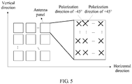
- the quantity of CSI-RS signals to be sent at each level includes a quantity of CSI-RS signals that have a same polarization direction in a horizontal direction and a quantity of CSI-RS signals that have a same polarization direction in a vertical direction
- the sampling rate at each level includes a sampling rate in the horizontal direction and a sampling rate in the vertical direction
- the CSI-RS configuration parameter further includes a CSI-RS send window parameter
- the CSI-RS send window parameter is used to represent a sending manner of the CSI-RS signal at each level
- the sending manner includes at least one of the following manners: a manner in which the CSI-RS signal at each level is sent by using a time domain window, a manner in which the CSI-RS signal at each level is sent by using a frequency domain window, or a manner in which the CSI-RS signal at each level is sent by using both a time domain window and a frequency domain window.
- the CSI-RS configuration parameter includes a quantity of CSI-RS signals to be sent by the access network device at a first level, a quantity of CSI-RSs to be sent at a second level, a sampling rate at the first level, and a sampling rate at the second level, and the receiving, by the access network device after sending, based on the quantity of CSI-RS signals at each level, a CSI-RS signal corresponding to each level to the UE, a beamforming parameter at each level that is reported by the UE for the CSI-RS signal at each level specifically includes:
- the first beamforming parameter includes an identifier of a first main beam in a horizontal antenna direction, an identifier of a second main beam in a vertical antenna direction, an offset relative to the first main beam in the horizontal antenna direction, and an offset relative to the second main beam in the vertical antenna direction; and the second beamforming parameter includes an identifier of a beam in the horizontal antenna direction, an identifier of a beam in the vertical antenna direction, and a phase difference in two antenna polarization directions.
- the access network device sends, to the UE, the CSI-RS configuration parameter that includes the quantity of CSI-RS signals at each level and the sampling rate at each level, and then sends the first CSI-RS signal to the UE based on the quantity of CSI-RS signals to be sent at the first level and the preset first beam group, so that the UE determines the first beamforming parameter based on the quantity of CSI-RS signals to be sent at the first level, the sampling rate at the first level, and the first CSI-RS signal, and reports the first beamforming parameter to the access network device, and the access network device then determines the second beam group based on the first beamforming parameter, and sends the second CSI-RS signal to the UE based on the quantity of CSI-RS signals to be sent at the second level and the second beam group, so that the UE determines the second beamforming parameter based on the quantity of CSI-RS signals to be sent at the second level, the sampling rate at the second level,
- the UE may calculate the accurate beamforming parameter based on the CSI-RS configuration parameter and the CSI-RS signal delivered at each level, the width of the beam represented by the beamforming parameter at each level is less than the width of the beamforming used for delivering the CSI-RS signal at each level, and the width of the beamforming used for delivering the CSI-RS signal at the current level is less than or equal to the width of the beam represented by the beamforming parameter reported at the previous level.
- the width of the beam represented by the beamforming parameter finally reported by the UE to the access network device is far less than the width of the beam reported by the UE to the access network device at the second level in the prior art, accuracy of the beam direction is greatly improved, and the beam is more directive. Therefore, when the access network device performs downlink data transmission, interference between neighboring cells can be obviously avoided, and average frequency efficiency of a cell and frequency efficiency of a cell-edge user are greatly improved.
- the CSI-RS send window parameter includes a first send window parameter and a second send window parameter
- the first send window parameter includes a start sending symbol or subframe of a CSI-RS signal in time domain, a symbol or subframe offset of the CSI-RS signal in time domain, and a total quantity of symbols or subframes occupied by the CSI-RS signal in time domain, and is used to indicate, to the UE, that the access network device sends a CSI-RS signal at the first level by using the time domain window
- the second send window parameter includes a start sending subcarrier, resource block, or sub-band of a CSI-RS signal in frequency domain, a subcarrier, resource block, or sub-band offset of the CSI-RS signal in frequency domain, and a total quantity of subcarriers, resource blocks, or sub-bands occupied by the CSI-RS signal in frequency domain, and is used to indicate, to the UE, that the access network device sends a CSI-RS signal at the second level by
- the access network device sends the CSI-RS signal at the first level in the time domain window, and sends the CSI-RS signal at the second level in the frequency domain window. Therefore, not only coverage performance of the CSI-RS signal at the first level can be enhanced, but also a measurement rate of the CSI-RS signal at the second level can be accelerated, thereby improving channel measurement accuracy, and improving a traffic channel transmission rate.
- an embodiment of the present invention provides an information transmission method, including:
- the quantity of CSI-RS signals to be sent at each level includes a quantity of CSI-RS signals that have a same polarization direction in a horizontal direction and a quantity of CSI-RS signals that have a same polarization direction in a vertical direction
- the sampling rate at each level includes a sampling rate in the horizontal direction and a sampling rate in the vertical direction
- the CSI-RS configuration parameter further includes a CSI-RS send window parameter
- the CSI-RS send window parameter is used to represent a sending manner of the CSI-RS signal at each level
- the sending manner includes at least one of the following manners: a manner in which the CSI-RS signal at each level is sent by using a time domain window, a manner in which the CSI-RS signal at each level is sent by using a frequency domain window, or a manner in which the CSI-RS signal at each level is sent by using both a time domain window and a frequency domain window.
- the CSI-RS configuration parameter includes a quantity of CSI-RS signals to be sent by the access network device at a first level, a quantity of CSI-RSs to be sent at a second level, a sampling rate at the first level, and a sampling rate at the second level, and the reporting, by the UE to the access network device, a beamforming parameter at each level based on a CSI-RS signal at each level and the sampling rate at each level after receiving the CSI-RS signal at each level that is sent by the access network device specifically includes:
- the first beamforming parameter includes an identifier of a first main beam in a horizontal antenna direction, an identifier of a second main beam in a vertical antenna direction, an offset relative to the first main beam in the horizontal antenna direction, and an offset relative to the second main beam in the vertical antenna direction; and the second beamforming parameter includes an identifier of a beam in the horizontal antenna direction, an identifier of a beam in the vertical antenna direction, and a phase difference in two antenna polarization directions.
- the CSI-RS send window parameter includes a first send window parameter and a second send window parameter
- the first send window parameter includes a start sending symbol or subframe of a CSI-RS signal in time domain, a symbol or subframe offset of the CSI-RS signal in time domain, and a total quantity of symbols or subframes occupied by the CSI-RS signal in time domain, and is used to indicate, to the UE, that the access network device sends a CSI-RS signal at the first level by using the time domain window
- the second send window parameter includes a start sending subcarrier, resource block, or sub-band of a CSI-RS signal in frequency domain, a subcarrier, resource block, or sub-band offset of the CSI-RS signal in frequency domain, and a total quantity of subcarriers, resource blocks, or sub-bands occupied by the CSI-RS signal in frequency domain, and is used to indicate, to the UE, that the access network device sends a CSI-RS signal at the second level by
- an embodiment of the present invention provides an access network device, including:
- the quantity of CSI-RS signals to be sent at each level includes a quantity of CSI-RS signals that have a same polarization direction in a horizontal direction and a quantity of CSI-RS signals that have a same polarization direction in a vertical direction
- the sampling rate at each level includes a sampling rate in the horizontal direction and a sampling rate in the vertical direction
- the CSI-RS configuration parameter further includes a CSI-RS send window parameter
- the CSI-RS send window parameter is used to represent a sending manner of the CSI-RS signal at each level
- the sending manner includes at least one of the following manners: a manner in which the CSI-RS signal at each level is sent by using a time domain window, a manner in which the CSI-RS signal at each level is sent by using a frequency domain window, or a manner in which the CSI-RS signal at each level is sent by using both a time domain window and a frequency domain window.
- the CSI-RS configuration parameter includes a quantity of CSI-RS signals to be sent by the access network device at a first level, a quantity of CSI-RSs to be sent at a second level, a sampling rate at the first level, and a sampling rate at the second level
- the receiving module specifically includes:
- the first beamforming parameter includes an identifier of a first main beam in a horizontal antenna direction, an identifier of a second main beam in a vertical antenna direction, an offset relative to the first main beam in the horizontal antenna direction, and an offset relative to the second main beam in the vertical antenna direction; and the second beamforming parameter includes an identifier of a beam in the horizontal antenna direction, an identifier of a beam in the vertical antenna direction, and a phase difference in two antenna polarization directions.
- the CSI-RS send window parameter includes a first send window parameter and a second send window parameter
- the first send window parameter includes a start sending symbol or subframe of a CSI-RS signal in time domain, a symbol or subframe offset of the CSI-RS signal in time domain, and a total quantity of symbols or subframes occupied by the CSI-RS signal in time domain, and is used to indicate, to the UE, that the access network device sends a CSI-RS signal at the first level by using the time domain window
- the second send window parameter includes a start sending subcarrier, resource block, or sub-band of a CSI-RS signal in frequency domain, a subcarrier, resource block, or sub-band offset of the CSI-RS signal in frequency domain, and a total quantity of subcarriers, resource blocks, or sub-bands occupied by the CSI-RS signal in frequency domain, and is used to indicate, to the UE, that the access network device sends a CSI-RS signal at the second level by
- an embodiment of the present invention provides a terminal device, including a receiving module, a processing module, and a sending module, where the receiving module is configured to receive a channel state information-reference signal CSI-RS configuration parameter sent by an access network device, where the CSI-RS configuration parameter includes a quantity of CSI-RS signals to be sent by the access network device at each level and a sampling rate at each level; and the processing module is configured to: after the receiving module receives a CSI-RS signal at each level that is sent by the access network device, determine a beamforming parameter at each level based on the CSI-RS signal at each level and the sampling rate at each level, and report the beamforming parameter at each level to the access network device by using the sending module, where a width of a beam represented by the beamforming parameter at each level is less than a width of beamforming used for delivering the CSI-RS signal at each level, and a width of beamforming used for delivering a CSI-RS signal at a current level is less than or equal to
- the quantity of CSI-RS signals to be sent at each level includes a quantity of CSI-RS signals that have a same polarization direction in a horizontal direction and a quantity of CSI-RS signals that have a same polarization direction in a vertical direction
- the sampling rate at each level includes a sampling rate in the horizontal direction and a sampling rate in the vertical direction
- the CSI-RS configuration parameter further includes a CSI-RS send window parameter
- the CSI-RS send window parameter is used to represent a sending manner of the CSI-RS signal at each level
- the sending manner includes at least one of the following manners: a manner in which the CSI-RS signal at each level is sent by using a time domain window, a manner in which the CSI-RS signal at each level is sent by using a frequency domain window, or a manner in which the CSI-RS signal at each level is sent by using both a time domain window and a frequency domain window.
- the CSI-RS configuration parameter includes a quantity of CSI-RS signals to be sent by the access network device at a first level, a quantity of CSI-RSs to be sent at a second level, a sampling rate at the first level, and a sampling rate at the second level
- the processing module specifically includes:
- the first beamforming parameter includes an identifier of a first main beam in a horizontal antenna direction, an identifier of a second main beam in a vertical antenna direction, an offset relative to the first main beam in the horizontal antenna direction, and an offset relative to the second main beam in the vertical antenna direction; and the second beamforming parameter includes an identifier of a beam in the horizontal antenna direction, an identifier of a beam in the vertical antenna direction, and a phase difference in two antenna polarization directions.
- the CSI-RS send window parameter includes a first send window parameter and a second send window parameter
- the first send window parameter includes a start sending symbol or subframe of a CSI-RS signal in time domain, a symbol or subframe offset of the CSI-RS signal in time domain, and a total quantity of symbols or subframes occupied by the CSI-RS signal in time domain, and is used to indicate, to the UE, that the access network device sends a CSI-RS signal at the first level by using the time domain window
- the second send window parameter includes a start sending subcarrier, resource block, or sub-band of a CSI-RS signal in frequency domain, a subcarrier, resource block, or sub-band offset of the CSI-RS signal in frequency domain, and a total quantity of subcarriers, resource blocks, or sub-bands occupied by the CSI-RS signal in frequency domain, and is used to indicate, to the UE, that the access network device sends a CSI-RS signal at the second level by
- an embodiment of the present invention provides an access network device, including:
- the quantity of CSI-RS signals to be sent at each level includes a quantity of CSI-RS signals that have a same polarization direction in a horizontal direction and a quantity of CSI-RS signals that have a same polarization direction in a vertical direction
- the sampling rate at each level includes a sampling rate in the horizontal direction and a sampling rate in the vertical direction
- the CSI-RS configuration parameter further includes a CSI-RS send window parameter
- the CSI-RS send window parameter is used to represent a sending manner of the CSI-RS signal at each level
- the sending manner includes at least one of the following manners: a manner in which the CSI-RS signal at each level is sent by using a time domain window, a manner in which the CSI-RS signal at each level is sent by using a frequency domain window, or a manner in which the CSI-RS signal at each level is sent by using both a time domain window and a frequency domain window.
- the CSI-RS configuration parameter includes a quantity of CSI-RS signals to be sent by the access network device at a first level, a quantity of CSI-RSs to be sent at a second level, a sampling rate at the first level, and a sampling rate at the second level;
- the receiver is specifically configured to: after the transmitter sends a first CSI-RS signal to the UE based on the quantity of CSI-RS signals to be sent at the first level and a preset first beam group, receive a first beamforming parameter reported by the UE based on the quantity of CSI-RS signals to be sent at the first level, the sampling rate at the first level, and the first CSI-RS signal, where a width of a beam represented by the first beamforming parameter is less than a width of a beam in the first beam group, a quantity of beams in the first beam group is equal to a quantity of first CSI-RS signals, and all the first CSI-RS signals have a same beamforming factor; the transmitter is configured to send a second
- the first beamforming parameter includes an identifier of a first main beam in a horizontal antenna direction, an identifier of a second main beam in a vertical antenna direction, an offset relative to the first main beam in the horizontal antenna direction, and an offset relative to the second main beam in the vertical antenna direction; and the second beamforming parameter includes an identifier of a beam in the horizontal antenna direction, an identifier of a beam in the vertical antenna direction, and a phase difference in two antenna polarization directions.
- the CSI-RS send window parameter includes a first send window parameter and a second send window parameter
- the first send window parameter includes a start sending symbol or subframe of a CSI-RS signal in time domain, a symbol or subframe offset of the CSI-RS signal in time domain, and a total quantity of symbols or subframes occupied by the CSI-RS signal in time domain, and is used to indicate, to the UE, that the access network device sends a CSI-RS signal at the first level by using the time domain window
- the second send window parameter includes a start sending subcarrier, resource block, or sub-band of a CSI-RS signal in frequency domain, a subcarrier, resource block, or sub-band offset of the CSI-RS signal in frequency domain, and a total quantity of subcarriers, resource blocks, or sub-bands occupied by the CSI-RS signal in frequency domain, and is used to indicate, to the UE, that the access network device sends a CSI-RS signal at the second level by
- an embodiment of the present invention provides a terminal device, including: a receiver, a processor, and a transmitter, where the receiver is configured to receive a channel state information-reference signal CSI-RS configuration parameter sent by an access network device, where the CSI-RS configuration parameter includes a quantity of CSI-RS signals to be sent by the access network device at each level and a sampling rate at each level; and the processor is configured to: after the receiver receives a CSI-RS signal at each level that is sent by the access network device, determine a beamforming parameter at each level based on the CSI-RS signal at each level and the sampling rate at each level, and report the beamforming parameter at each level to the access network device by using the transmitter, where a width of a beam represented by the beamforming parameter at each level is less than a width of beamforming used for delivering the CSI-RS signal at each level, and a width of beamforming used for delivering a CSI-RS signal at a current level is less than or equal to a width of a
- the quantity of CSI-RS signals to be sent at each level includes a quantity of CSI-RS signals that have a same polarization direction in a horizontal direction and a quantity of CSI-RS signals that have a same polarization direction in a vertical direction
- the sampling rate at each level includes a sampling rate in the horizontal direction and a sampling rate in the vertical direction
- the CSI-RS configuration parameter further includes a CSI-RS send window parameter
- the CSI-RS send window parameter is used to represent a sending manner of the CSI-RS signal at each level
- the sending manner includes at least one of the following manners: a manner in which the CSI-RS signal at each level is sent by using a time domain window, a manner in which the CSI-RS signal at each level is sent by using a frequency domain window, or a manner in which the CSI-RS signal at each level is sent by using both a time domain window and a frequency domain window.
- the CSI-RS configuration parameter includes a quantity of CSI-RS signals to be sent by the access network device at a first level, a quantity of CSI-RSs to be sent at a second level, a sampling rate at the first level, and a sampling rate at the second level;
- the processor is specifically configured to: after the receiver receives a first CSI-RS signal sent by the access network device based on the quantity of CSI-RS signals to be sent at the first level and a first beam group, determine a first beamforming parameter based on the quantity of CSI-RS signals to be sent at the first level, the sampling rate at the first level, and the first CSI-RS signal, and report the first beamforming parameter to the access network device by using the transmitter, where a width of a beam represented by the first beamforming parameter is less than a width of a beam in the first beam group, a quantity of beams in the first beam group is equal to a quantity of first CSI-RS signals, and all the first CSI-RS signals have a same beam
- the first beamforming parameter includes an identifier of a first main beam in a horizontal antenna direction, an identifier of a second main beam in a vertical antenna direction, an offset relative to the first main beam in the horizontal antenna direction, and an offset relative to the second main beam in the vertical antenna direction; and the second beamforming parameter includes an identifier of a beam in the horizontal antenna direction, an identifier of a beam in the vertical antenna direction, and a phase difference in two antenna polarization directions.
- the CSI-RS send window parameter includes a first send window parameter and a second send window parameter
- the first send window parameter includes a start sending symbol or subframe of a CSI-RS signal in time domain, a symbol or subframe offset of the CSI-RS signal in time domain, and a total quantity of symbols or subframes occupied by the CSI-RS signal in time domain, and is used to indicate, to the UE, that the access network device sends a CSI-RS signal at the first level by using the time domain window
- the second send window parameter includes a start sending subcarrier, resource block, or sub-band of a CSI-RS signal in frequency domain, a subcarrier, resource block, or sub-band offset of the CSI-RS signal in frequency domain, and a total quantity of subcarriers, resource blocks, or sub-bands occupied by the CSI-RS signal in frequency domain, and is used to indicate, to the UE, that the access network device sends a CSI-RS signal at the second level by
- An information transmission method in the embodiments of the present invention is applicable to a downlink in any mobile communications system in which a plurality of antennas are used, for example, a 5G communications system in which a plurality of antennas are used, or a Long Term Evolution (Long Term Evolution, LTE for short) system in which a multiple-antenna system is used or an evolved version thereof; and is also applicable to sending of an uplink sounding reference signal.
- the communications system in which a plurality of antennas are used may include an access network device and at least one terminal device.
- the access network device delivers a CSI-RS signal to the terminal device, so that the UE performs CSI feedback for the access network device based on the CSI-RS signal.
- information that is actually fed back is a beamforming parameter, and the access network device can perform downlink data transmission based on the beamforming parameter.
- the access network device may be a base station, or may be another communications device that can communicate with the UE and that can perform downlink scheduling.
- the base station in this application may be a device that communicates with a wireless terminal by using one or more sectors on an air interface in an access network.
- the base station may be configured to mutually convert a received over-the-air frame and an IP packet and serve as a router between the wireless terminal and a remaining part of the access network.
- the remaining part of the access network may include an Internet protocol (IP) network.
- IP Internet protocol
- the base station may further coordinate attribute management of the air interface.
- the base station may be an evolved NodeB (NodeB, eNB, or e-NodeB, evolved NodeB) in LTE.
- the terminal device in this application may be a wireless terminal device or a wired terminal device.
- the wireless terminal may be a handheld device with a wireless connection function, another processing device connected to a wireless modem, or a mobile terminal that communicates with one or more core networks by using a radio access network.
- the wireless terminal may be a mobile phone (or referred to as a "cellular" phone) or a computer with a mobile terminal.
- the wireless terminal may alternatively be a portable, pocket-sized, handheld, computer built-in, or in-vehicle mobile apparatus.
- the wireless terminal may be user equipment (English: user equipment, UE for short).
- an access network device delivers CSI-RS signals to UE at two levels, and the UE performs CSI feedback for the access network device based on a CSI-RS signal delivered at each level.
- a basic principle of the CSI feedback is as follows: The UE performs channel estimation based on the CSI-RS signal delivered at each level, to select a CSI-RS sequence number corresponding to a CSI-RS signal with optimal signal quality, and reports the CSI-RS sequence number to a base station side. After receiving the CSI-RS signal, the UE merely performs simple beam selection. Therefore, in the prior art, the CSI-RS sequence number reported by the UE is inaccurate, in other words, a CSI-RS beamforming direction reported by the UE is inaccurate. Consequently, average frequency efficiency of a cell and frequency efficiency of a cell-edge user are reduced, and unnecessary interference between neighboring cells is caused.
- the method in the embodiments of the present invention is intended to resolve the foregoing problem in the prior art.
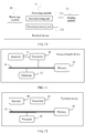
- FIG. 2 is a signaling flowchart of Embodiment 1 of an information transmission method according to an embodiment of the present invention.
- This embodiment relates to a specific process in which an access network device delivers a CSI-RS configuration parameter and a CSI-RS signal to UE so that the UE can obtain, through calculation based on the CSI-RS parameter and a CSI-RS signal delivered at each level, a beamforming parameter corresponding to each level and report the beamforming parameter to the access network device.
- a width of a beam represented by the beamforming parameter reported by the UE at each level is less than a width of beamforming used by the UE to deliver the CSI-RS signal at the level, to be specific, the beam represented by the beamforming parameter reported by the UE to the access network device has a more accurate direction and is more directive. Therefore, the access network device performs more accurate downlink data transmission, thereby avoiding interference between neighboring cells.
- the method includes the following steps.
- the access network device sends a CSI-RS configuration parameter to the terminal device UE.
- the CSI-RS configuration parameter includes a quantity of CSI-RS signals to be sent by the access network device at each level and a sampling rate at each level.
- the UE receives the CSI-RS configuration parameter sent by the access network device.
- the access network device before sending a CSI-RS signal to the UE, the access network device sends the CSI-RS configuration parameter to the UE.
- the CSI-RS configuration parameter includes the quantity of CSI-RS signals to be sent by the access network device at each level and the sampling rate at each level.
- the UE may learn of, based on the CSI-RS parameter, a quantity of levels that need to be used by the access network device to deliver CSI-RS signals and the quantity of CSI-RS signals delivered at each level, so that the UE can accurately receive all the CSI-RS signals at each level.
- the access network device After sending, based on a quantity of CSI-RS signals at each level, a CSI-RS signal corresponding to each level to the UE, the access network device receives a beamforming parameter at each level that is reported by the UE for the CSI-RS signal at each level.
- the beamforming parameter at each level is determined by the UE based on the CSI-RS signal at each level and the sampling rate at each level.
- a width of a beam represented by the beamforming parameter at each level is less than a width of beamforming used for delivering the CSI-RS signal at each level, and a width of beamforming used for delivering a CSI-RS signal at a current level is less than or equal to a width of a beam represented by a beamforming parameter reported at a previous level.
- the access network device may send, based on the quantity of the CSI-RS signals at each level that is in the CSI-RI configuration parameter, the CSI-RS signal corresponding to each level to the UE.
- the access network device sends the CSI-RS signals to the UE at levels, and for the CSI-RS signal delivered at each level, the UE reports the beamforming parameter for the CSI-RS signal at the level.
- the beamforming parameter is determined by the UE based on the CSI-RS signal at the level and the sampling rate at the level.
- the UE may determine a precoding codebook based on the quantity of CSI-RS signals at the level and the sampling rate at the level, select a beamforming vector (the beamforming vector may be one type of the beamforming parameter) with a maximum downlink transmission rate from the precoding codebook, and feed back a beam vector sequence number to the access network device.
- the access network device delivers the CSI-RS signals at levels, and therefore the UE reports beamforming parameters to the access network device at levels for the CSI-RS signals delivered at levels.
- a simple example may be used herein.
- the access network device first delivers a CSI-RS signal at the first level to the UE based on the quantity of CSI-RS signals at the first level, then delivers a CSI-RS signal at the second level to the UE after receiving a beamforming parameter at the first level that is reported by the UE based on the quantity of CSI-RS signals at the first level and the sampling rate
- the CSI-RS signal at each level that is delivered by the access network device to the UE is a signal obtained after beamforming.
- all CSI-RS signals delivered at each level have a same beamforming factor.
- the access network device may further perform a sweeping operation on the CSI-RS signal, to obtain a plurality of groups of CSI-RS signals. All CSI-RS signals in each group have a same beamforming factor, but CSI-RS signals in adjacent groups may have different beamforming factors.
- the width of the beam represented by the beamforming parameter at each level is less than the width of the beamforming used for delivering the CSI-RS signal at the level, and the width of the beamforming used for delivering the CSI-RS signal at the current level is less than or equal to the width of the beam represented by the beamforming parameter reported at the previous level.
- a width of a beam (which is set to a beam a) represented by the beamforming parameter at the first level that is reported by the UE is less than a width of beamforming (which is set to a beam A) used by the access network device to deliver the CSI-RS signal at the first level
- a width of a beam (which is set to a beam b) represented by the beamforming parameter at the second level that is reported by the UE is less than a width of beamforming (which is set to a beam B) used by the access network device to deliver the CSI-RS signal at the second level
- a width of a beam (which is set to a beam c) represented by the beamforming parameter at the third level that is reported by the UE is less than a width of beamforming (which is set to a beam group C) used by the access network device to deliver the CSI-RS signal at the third level.
- the width of the beamforming (namely, the beam B) used by the access network device to deliver the CSI-RS signal at the second level is less than or equal to the width of the beam (namely, the beam a) represented by the beamforming parameter reported by the UE at the first level
- the width of the beamforming (namely, the beam C) used by the access network device to deliver the CSI-RS signal at the third level is less than or equal to the width of the beam (namely, the beam b) represented by the beamforming parameter reported by the UE at the second level.
- a specific relationship is "the width of the beam A">"the width of the beam a" ⁇ "the width of the beam B">”the width of the beam b" ⁇ ”the width of the beam C">”the width of the beam c". It may be learned that in the entire process in which delivery and reporting are performed at levels, widths of used beams gradually decrease, the beam (namely, the beam c) represented by the beamforming parameter finally reported to the access network device has a minimum width, and the beam has an accurate beam direction, and is directive. Therefore, when the access network device performs downlink data transmission, interference between neighboring cells can be obviously avoided, and average frequency efficiency of a cell and frequency efficiency of a cell-edge user are greatly improved.
- UE merely performs simple beam selection based on CSI-RS signals delivered by an access network device at levels.
- the UE selects, from beams used to deliver the CSI-RS signals, a beam corresponding to a CSI-RS signal with high signal quality, and reports a sequence number of the beam to the access network device, in other words, a width of a beam used to deliver a CSI-RS signal at a level is the same as a width of a beam reported to the access network device at the same level. Consequently, a beam finally reported to the access network device still has a relatively large width, and is not directive.
- CSI-RS signals are delivered at two levels, and CSI-RS sequence numbers are reported at two levels.
- the access network device performs beamforming on CSI-RS signals at a first level by using a first beam group (the first beam group includes different beams), and then delivers the CSI-RS signals, where all the CSI-RS signals delivered at the first level have different beamforming factors.
- the UE selects, based on the CSI-RS signals at the first level, a beam (it is assumed that the beam is a beam D in the first beam group) corresponding to a CSI-RS signal with optimal signal quality, and reports the beam to the access network device.
- the access network device determines a relatively narrow second beam group based on the beam D to continue to deliver a CSI-RS signal at a second level.
- the UE selects a beam E from the second beam group based on a same process.
- a width of the beam E is less than a width of the beam D.
- the beam D reported at the first level and the beam D used to deliver a CSI-RS signal at the first level have a same width
- the beam E reported at the second level and the beam E used to deliver a CSI-RS signal at the second level have a same width. Therefore, there is only one beam width decrease process (to be specific, the width of the beam E is less than the width of the beam D) in the prior art.
- the foregoing example is used.
- There is one beam width decrease process (to be specific, "the width of the beam A">"the width of the beam a") in a process from delivery at the first level to reporting at the first level
- there may be one beam width decrease process ("the width of the beam a" ⁇ "the width of the beam B") in a process from reporting at the first level to delivery at the second level
- there is also one beam width decrease process ("the width of the beam B">"the width of the beam b") in a process from delivery at the second level to reporting at the second level. Therefore, there are a plurality of beam width decrease processes in this embodiment of the present invention.
- the width of the beam finally reported to the access network device in this embodiment of the present invention is far less than the width of the beam finally reported by the UE to the access network device in the prior art, and the beam has a more accurate beam direction. Therefore, when the access network device performs downlink data transmission, interference between neighboring cells can be obviously avoided, and average frequency efficiency of a cell and frequency efficiency of a cell-edge user are greatly improved.
- the access network device sends, to the UE, the CSI-RS configuration parameter that includes the quantity of CSI-RS signals at each level and the sampling rate at each level, and after sending, based on the quantity of CSI-RS signals at each level, the CSI-RS signal corresponding to each level to the UE, the access network device receives the beamforming parameter at each level that is reported by the UE for the CSI-RS signal at each level.
- the UE may calculate an accurate beamforming parameter based on the CSI-RS configuration parameter and the CSI-RS signal delivered at each level, the width of the beam represented by the beamforming parameter at each level is less than the width of the beamforming used for delivering the CSI-RS signal at each level, and the width of the beamforming used for delivering the CSI-RS signal at the current level is less than or equal to the width of the beam represented by the beamforming parameter reported at the previous level.
- the width of the beam represented by the beamforming parameter finally reported by the UE to the access network device is far less than the width of the beam reported by the UE to the access network device at the second level in the prior art, accuracy of the beam direction is greatly improved, and the beam is more directive. Therefore, when the access network device performs downlink data transmission, interference between neighboring cells can be obviously avoided, and average frequency efficiency of a cell and frequency efficiency of a cell-edge user are greatly improved.
- the quantity of the CSI-RS signals to be sent at each level that is in the CSI-RS configuration parameter may include a quantity of CSI-RS signals that have a same polarization direction in a horizontal direction and a quantity of CSI-RS signals that have a same polarization direction in a vertical direction
- the sampling rate at each level may include a sampling rate in the horizontal direction and a sampling rate in the vertical direction.
- FIG. 3 is a signaling flowchart of Embodiment 2 of an information transmission method according to an embodiment of the present invention.
- a CSI-RS configuration parameter includes a quantity of CSI-RS signals to be sent by the access network device at a first level, a quantity of CSI-RSs to be sent at a second level, a sampling rate at the first level, and a sampling rate at the second level.
- This embodiment relates to a specific process in which the access network device delivers CSI-RS signals at two levels and UE reports beamforming parameters at two levels to improve accuracy of a beam direction reported to a base station. Based on the foregoing embodiment, as shown in FIG. 3 , the method includes the following steps.
- the access network device sends a CSI-RS configuration parameter to the UE.
- the CSI-RS configuration parameter includes a quantity of CSI-RS signals to be sent by the access network device at a first level, a quantity of CSI-RSs to be sent at a second level, a sampling rate at the first level, and a sampling rate at the second level.
- the quantity of CSI-RS signals to be sent at the first level includes a quantity of CSI-RS signals that are to be sent at the first level and that have a same polarization direction in a horizontal direction and a quantity of CSI-RS signals that are to be sent at the first level and that have a same polarization direction in a vertical direction
- the sampling rate at the first level includes a sampling rate of a CSI-RS signal at the first level in the horizontal direction and a sampling rate of a CSI-RS signal at the first level in the vertical direction
- the quantity of CSI-RS signals to be sent at the second level includes a quantity of CSI-RS signals that are to be sent at the second level and that have a same polarization direction in a horizontal direction and a quantity of CSI-RS signals that are to be sent at the second level and that have a same polarization direction in a vertical direction
- the sampling rate at the second level includes a sampling rate of a CSI-RS signal at the second level
- the access network device sends a first CSI-RS signal to the UE based on a quantity of CSI-RS signals to be sent at a first level and a preset first beam group.
- a quantity of beams in the first beam group is equal to a quantity of first CSI-RS signals, and all the first CSI-RS signals have a same beamforming factor.
- the access network device when sending the CSI-RS signal at the first level to the UE, the access network device needs to perform beamforming on the to-be-sent CSI-RS signal at the first level, in other words, perform beamforming on the to-be-sent CSI-RS signal by using a beam in the preset first beam group.
- Each to-be-sent CSI-RS signal becomes the first CSI-RS signal after the beamforming, and all the first CSI-RS signals have the same beamforming factor.
- the access network device then sends all the first CSI-RS signals to the UE with reference to the quantity of CSI-RS signals to be sent at the first level.
- the first beam group includes M beams, and a width of each beam is P, as shown in a schematic diagram of feeding back a beamforming parameter in FIG. 4 .
- the UE determines a first beamforming parameter based on the quantity of CSI-RS signals to be sent at the first level, a sampling rate at the first level, and the first CSI-RS signal.
- the UE reports the first beamforming parameter to the access network device.
- a width of a beam represented by the first beamforming parameter is less than a width of the beam in the first beam group.
- the UE determines the first beamforming parameter with reference to the quantity of CSI-RS signals to be sent at the first level, the sampling rate at the first level, and all the first CSI-RS signals, and reports the first beamforming parameter to the access network device.
- the width of the beam represented by the determined first beamforming parameter is less than the width of the beam in the first beam group. Therefore, it may be learned that there is one beam width decrease process herein.
- the UE may send the first beamforming parameter through a channel such as a downlink broadcast channel or a control channel.
- the first beamforming parameter may include an identifier i1,1 of a first main beam in a horizontal antenna direction, an identifier i1,2 of a second main beam in a vertical antenna direction, an offset ⁇ i1,1 relative to the first main beam in the horizontal antenna direction, and an offset ⁇ i1,1 relative to the second main beam in the vertical antenna direction.
- the first beamforming parameter may represent a group of beams, and a width (which is set to p) of each beam in the group of beams represented by the first beamforming parameter is less than the width P of the beam in the first beam group.
- m in FIG. 4 is an identifier of a main beam (the first main beam or the second main beam)
- k is an offset relative to the main beam.
- the access network device determines a second beam group based on the first beamforming parameter.
- a width of a beam in the second beam group is less than or equal to the width of the beam represented by the first beamforming parameter, a quantity of beams in the second beam group is equal to a quantity of second CSI-RS signals, and all the second CSI-RS signals have a same beamforming factor.
- the access network device determines the second beam group based on the beam represented by the first beamforming parameter, in other words, the second beam group is related to the first beamforming parameter, and the width of the beam in the second beam group is less than or equal to the width of the beam represented by the first beamforming parameter. Therefore, when the width (which is set to Q) of the beam in the second beam group determined by the access network device is less than the width p of the beam represented by the first beamforming parameter, there is also one beam width decrease process herein.
- the access network device sends a second CSI-RS signal to the UE based on a quantity of CSI-RS signals to be sent at a second level and the second beam group.
- the access network device determines the second beam group
- the access network device performs beamforming on a to-be-sent CSI-RS signal at the second level by using a beam in the second beam group.
- Each to-be-sent CSI-RS signal becomes the second CSI-RS signal after the beamforming, and all the second CSI-RS signals have the same beamforming factor.
- the access network device then sends all the second CSI-RS signals to the UE with reference to the quantity of CSI-RS signals to be sent at the second level.
- the second beam group includes N beams, and a width of each beam is Q, as shown in the schematic diagram of feeding back a beamforming parameter in FIG. 4 .
- the UE determines a second beamforming parameter based on the quantity of CSI-RS signals to be sent at the second level, a sampling rate at the second level, and the second CSI-RS signal.
- a width of beamforming represented by the second beamforming parameter is less than the width of the beam in the second beam group.
- the UE sends the second beamforming parameter to the access network device.
- the UE determines the second beamforming parameter with reference to the quantity of CSI-RS signals to be sent at the second level, the sampling rate at the second level, and all the second CSI-RS signals, and reports the second beamforming parameter to the access network device.
- the width (which is set to q) of the beam represented by the determined second beamforming parameter is less than the width Q of the beam in the second beam group. Therefore, it may be learned that there is also one beam width decrease process herein.
- the UE may send the second beamforming parameter through a downlink traffic channel.
- the second beamforming parameter may include an identifier i2,1 of a beam in the horizontal antenna direction, an identifier i2,2 of a beam in the vertical antenna direction, and a phase difference i2,c in two antenna polarization directions.
- the second beamforming parameter represents a narrow beam n, to be specific, the identifier of the beam in the horizontal antenna direction and the identifier of the beam in the vertical antenna direction are identifiers of the narrow beam, as shown in FIG. 4 .
- a 5G mobile communications system for an antenna model, refer to FIG. 5 .
- the access network device performs downlink data transmission based on the second beamforming parameter.
- the access network device delivers the CSI-RS signals at two levels, and the UE reports the beamforming parameters at two levels, there are a plurality of beam width decrease processes, so that the width of the beam represented by the second beamforming parameter finally reported by the UE to the access network device is far less than a width of a beam reported by UE to an access network device at a second level in the prior art, accuracy of a beam direction is greatly improved, and the beam is more directive. Therefore, when the access network device performs downlink data transmission, interference between neighboring cells can be obviously avoided, and average frequency efficiency of a cell and frequency efficiency of a cell-edge user are greatly improved.
- the access network device sends, to the UE, the CSI-RS configuration parameter that includes a quantity of CSI-RS signals at each level and a sampling rate at each level, and then sends the first CSI-RS signal to the UE based on the quantity of CSI-RS signals to be sent at the first level and the preset first beam group, so that the UE determines the first beamforming parameter based on the quantity of CSI-RS signals to be sent at the first level, the sampling rate at the first level, and the first CSI-RS signal, and reports the first beamforming parameter to the access network device, and the access network device then determines the second beam group based on the first beamforming parameter, and sends the second CSI-RS signal to the UE based on the quantity of CSI-RS signals to be sent at the second level and the second beam group, so that the UE determines the second beamforming parameter based on the quantity of CSI-RS signals to be sent at the second level, the sampling rate at the second
- the UE may calculate an accurate beamforming parameter based on the CSI-RS configuration parameter and a CSI-RS signal delivered at each level, a width of a beam represented by a beamforming parameter at each level is less than a width of beamforming used for delivering a CSI-RS signal at each level, and a width of beamforming used for delivering a CSI-RS signal at a current level is less than or equal to a width of a beam represented by a beamforming parameter reported at a previous level.
- the width of the beam represented by the beamforming parameter finally reported by the UE to the access network device is far less than the width of the beam reported by the UE to the access network device at the second level in the prior art, accuracy of the beam direction is greatly improved, and the beam is more directive. Therefore, when the access network device performs downlink data transmission, interference between neighboring cells can be obviously avoided, and average frequency efficiency of a cell and frequency efficiency of a cell-edge user are greatly improved.
- the CSI-RS configuration parameter may further include a CSI-RS send window parameter, the CSI-RS send window parameter is used to represent a sending manner of a CSI-RS signal at each level, and the sending manner includes at least one of the following manners: a manner in which the CSI-RS signal at each level is sent by using a time domain window, a manner in which the CSI-RS signal at each level is sent by using a frequency domain window, or a manner in which the CSI-RS signal at each level is sent by using both a time domain window and a frequency domain window.
- the CSI-RS signal at the first level may be sent by using the time domain window, or may be sent by using the frequency domain window
- the CSI-RS signal at the second level may be sent by using the time domain window, or may be sent by using the frequency domain window.
- the CSI-RS signals at the first level may be sent in a same sending manner or different sending manners.
- the access network device may send the CSI-RS signal at the first level in the time domain window, and send the CSI-RS signal at the second level in the frequency domain window, in other words, the CSI-RS send window parameter includes a first send window parameter and a second send window parameter.
- the first send window parameter includes a start sending symbol or subframe Tstart of a CSI-RS signal in time domain, a symbol or subframe offset Toffset of the CSI-RS signal in time domain, and a total quantity Ttotal of symbols or subframes occupied by the CSI-RS signal in time domain, and is used to indicate, to the UE, that the access network device sends the CSI-RS signal at the first level by using the time domain window.
- the second send window parameter includes a start sending subcarrier, resource block, or sub-band Fstart of a CSI-RS signal in frequency domain, a subcarrier, resource block, or sub-band offset Foffset of the CSI-RS signal in frequency domain, and a total quantity Ftotal of subcarriers, resource blocks, or sub-bands occupied by the CSI-RS signal in frequency domain, and is used to indicate, to the UE, that the access network device sends the CSI-RS signal at the second level by using the frequency domain window.
- a CSI-RS signal at a first level is sent in a time domain window, and a sending period is relatively long. Because a beam used to perform beamforming on the CSI-RS signal at the first level is relatively wide, when all CSI-RS signals are sent in a time division manner, all transmit power may be concentrated on a beam corresponding to a CSI-RS signal for forming, and therefore coverage performance of the CSI-RS signal at the first level can be enhanced.
- CSI-RS signals at a second level are sent in a same subframe in a frequency division manner.
- each CSI-RS signal may occupy several subcarriers in the same subframe for sending, so that fast channel measurement can be implemented in one subframe, facilitating traffic channel sending, and improving a traffic channel transmission rate.
- the access network device sends the CSI-RS signal at the first level in the time domain window, and sends the CSI-RS signal at the second level in the frequency domain window. Therefore, not only the coverage performance of the CSI-RS signal at the first level can be enhanced, but also a measurement rate of the CSI-RS signal at the second level can be accelerated, thereby improving channel measurement accuracy, and improving a traffic channel transmission rate.
- the program may be stored in a computer readable storage medium. When the program runs, the steps of the method embodiments are performed.
- the storage medium includes any medium that can store program code, such as a ROM, a RAM, a magnetic disk, or an optical disc.
- FIG. 7 is a schematic structural diagram of Embodiment 1 of an access network device according to an embodiment of the present invention.
- the access network device may execute the foregoing method embodiments.
- the access network device may include a sending module 10 and a receiving module 11.
- the sending module 10 is configured to send a channel state information-reference signal CSI-RS configuration parameter to a terminal device UE.
- the CSI-RS configuration parameter includes a quantity of CSI-RS signals to be sent by the access network device at each level and a sampling rate at each level.
- the receiving module 11 is configured to: after the sending module 10 sends, based on the quantity of CSI-RS signals at each level, a CSI-RS signal corresponding to each level to the UE, receive a beamforming parameter at each level that is reported by the UE for the CSI-RS signal at each level.
- the beamforming parameter at each level is determined by the UE based on the CSI-RS signal at each level and the sampling rate at each level, a width of a beam represented by the beamforming parameter at each level is less than a width of beamforming used for delivering the CSI-RS signal at each level, and a width of beamforming used for delivering a CSI-RS signal at a current level is less than or equal to a width of a beam represented by a beamforming parameter reported at a previous level.
- the sending module 10 may be implemented by corresponding hardware or software, for example, may be implemented by a transmitter, a transmit antenna, or a transmitter chip.
- the receiving module 11 may be implemented by corresponding hardware or software, for example, may be implemented by a receiver, a receive antenna, or a receiver chip. This is not limited in this embodiment of the present invention.
- the access network device provided in this embodiment of the present invention may execute the foregoing method embodiments, and an implementation principle and a technical effect thereof are similar. Details are not described herein.
- the quantity of CSI-RS signals to be sent at each level includes a quantity of CSI-RS signals that have a same polarization direction in a horizontal direction and a quantity of CSI-RS signals that have a same polarization direction in a vertical direction
- the sampling rate at each level includes a sampling rate in the horizontal direction and a sampling rate in the vertical direction.
- the CSI-RS configuration parameter further includes a CSI-RS send window parameter
- the CSI-RS send window parameter is used to represent a sending manner of the CSI-RS signal at each level
- the sending manner includes at least one of the following manners: a manner in which the CSI-RS signal at each level is sent by using a time domain window, a manner in which the CSI-RS signal at each level is sent by using a frequency domain window, or a manner in which the CSI-RS signal at each level is sent by using both a time domain window and a frequency domain window.
- FIG. 8 is a schematic structural diagram of Embodiment 2 of an access network device according to an embodiment of the present invention.
- the CSI-RS configuration parameter includes a quantity of CSI-RS signals to be sent by the access network device at a first level, a quantity of CSI-RSs to be sent at a second level, a sampling rate at the first level, and a sampling rate at the second level.
- the receiving module 11 specifically includes a first receiving unit 111, a determining unit 112, and a second receiving unit 113.
- the first receiving unit 111 is configured to: after the sending module 10 sends a first CSI-RS signal to the UE based on the quantity of CSI-RS signals to be sent at the first level and a preset first beam group, receive a first beamforming parameter reported by the UE based on the quantity of CSI-RS signals to be sent at the first level, the sampling rate at the first level, and the first CSI-RS signal.
- a width of a beam represented by the first beamforming parameter is less than a width of a beam in the first beam group, a quantity of beams in the first beam group is equal to a quantity of first CSI-RS signals, and all the first CSI-RS signals have a same beamforming factor.
- the determining unit 112 is configured to determine a second beam group based on the first beamforming parameter.
- the sending module 10 is further configured to send a second CSI-RS signal to the UE based on the quantity of CSI-RS signals to be sent at the second level and the second beam group.
- a width of a beam in the second beam group is less than or equal to the width of the beam represented by the first beamforming parameter, a quantity of beams in the second beam group is equal to a quantity of second CSI-RS signals, and all the second CSI-RS signals have a same beamforming factor.
- the second receiving unit 113 is configured to receive a second beamforming parameter reported by the UE based on the quantity of CSI-RS signals to be sent at the second level, the sampling rate at the second level, and the second CSI-RS signal.
- a width of beamforming represented by the second beamforming parameter is less than the width of the beam in the second beam group.
- the first beamforming parameter includes an identifier of a first main beam in a horizontal antenna direction, an identifier of a second main beam in a vertical antenna direction, an offset relative to the first main beam in the horizontal antenna direction, and an offset relative to the second main beam in the vertical antenna direction; and the second beamforming parameter includes an identifier of a beam in the horizontal antenna direction, an identifier of a beam in the vertical antenna direction, and a phase difference in two antenna polarization directions.
- the CSI-RS send window parameter includes a first send window parameter and a second send window parameter
- the first send window parameter includes a start sending symbol or subframe of a CSI-RS signal in time domain, a symbol or subframe offset of the CSI-RS signal in time domain, and a total quantity of symbols or subframes occupied by the CSI-RS signal in time domain, and is used to indicate, to the UE, that the access network device sends a CSI-RS signal at the first level by using the time domain window
- the second send window parameter includes a start sending subcarrier, resource block, or sub-band of a CSI-RS signal in frequency domain, a subcarrier, resource block, or sub-band offset of the CSI-RS signal in frequency domain, and a total quantity of subcarriers, resource blocks, or sub-bands occupied by the CSI-RS signal in frequency domain, and is used to indicate, to the UE, that the access network device sends a CSI-RS signal at the second level by using the frequency
- the access network device provided in this embodiment of the present invention may execute the foregoing method embodiments, and an implementation principle and a technical effect thereof are similar. Details are not described herein.
- FIG. 9 is a schematic structural diagram of Embodiment 1 of a terminal device according to an embodiment of the present invention. As shown in FIG. 9 , the terminal device includes a receiving module 20, a processing module 21, and a sending module 22.
- the receiving module 20 is configured to receive a channel state information-reference signal CSI-RS configuration parameter sent by an access network device.
- the CSI-RS configuration parameter includes a quantity of CSI-RS signals to be sent by the access network device at each level and a sampling rate at each level.
- the processing module 21 is configured to: after the receiving module 20 receives a CSI-RS signal at each level that is sent by the access network device, determine a beamforming parameter at each level based on the CSI-RS signal at each level and the sampling rate at each level, and report the beamforming parameter at each level to the access network device by using the sending module 22.
- a width of a beam represented by the beamforming parameter at each level is less than a width of beamforming used for delivering the CSI-RS signal at each level, and a width of beamforming used for delivering a CSI-RS signal at a current level is less than or equal to a width of a beam represented by a beamforming parameter reported at a previous level.
- the sending module 22 may be implemented by corresponding hardware or software, for example, may be implemented by a transmitter, a transmit antenna, or a transmitter chip.
- the receiving module 20 may be implemented by corresponding hardware or software, for example, may be implemented by a receiver, a receive antenna, or a receiver chip. This is not limited in this embodiment of the present invention.
- the processing module 21 may be implemented by a corresponding processor or processing chip in the terminal device.
- the terminal device provided in this embodiment of the present invention may execute the foregoing method embodiments, and an implementation principle and a technical effect thereof are similar. Details are not described herein.
- the quantity of CSI-RS signals to be sent at each level includes a quantity of CSI-RS signals that have a same polarization direction in a horizontal direction and a quantity of CSI-RS signals that have a same polarization direction in a vertical direction
- the sampling rate at each level includes a sampling rate in the horizontal direction and a sampling rate in the vertical direction.
- the CSI-RS configuration parameter further includes a CSI-RS send window parameter
- the CSI-RS send window parameter is used to represent a sending manner of the CSI-RS signal at each level
- the sending manner includes at least one of the following manners: a manner in which the CSI-RS signal at each level is sent by using a time domain window, a manner in which the CSI-RS signal at each level is sent by using a frequency domain window, or a manner in which the CSI-RS signal at each level is sent by using both a time domain window and a frequency domain window.
- FIG. 10 is a schematic structural diagram of Embodiment 2 of a terminal device according to an embodiment of the present invention.
- the CSI-RS configuration parameter includes a quantity of CSI-RS signals to be sent by the access network device at a first level, a quantity of CSI-RSs to be sent at a second level, a sampling rate at the first level, and a sampling rate at the second level.
- the processing module 21 specifically includes a first processing unit 221 and a second processing unit 222.
- the first processing unit 221 is configured to: after the receiving module 20 receives a first CSI-RS signal sent by the access network device based on the quantity of CSI-RS signals to be sent at the first level and a first beam group, determine a first beamforming parameter based on the quantity of CSI-RS signals to be sent at the first level, the sampling rate at the first level, and the first CSI-RS signal, and report the first beamforming parameter to the access network device by using the sending module 22.
- a width of a beam represented by the first beamforming parameter is less than a width of a beam in the first beam group, a quantity of beams in the first beam group is equal to a quantity of first CSI-RS signals, and all the first CSI-RS signals have a same beamforming factor.
- the second processing unit 222 is configured to: after the receiving module 20 receives a second CSI-RS signal sent by the access network device based on the quantity of CSI-RS signals to be sent at the second level and a second beam group, determine a second beamforming parameter based on the quantity of CSI-RS signals to be sent at the second level, the sampling rate at the second level, and the second CSI-RS signal, and report the second beamforming parameter to the access network device by using the sending module 22.
- the second beam group is determined by the access network device based on the first beamforming parameter, a width of a beam in the second beam group is less than or equal to the width of the beam represented by the first beamforming parameter, a quantity of beams in the second beam group is equal to a quantity of second CSI-RS signals, all the second CSI-RS signals have a same beamforming factor, and a width of beamforming represented by the second beamforming parameter is less than the width of the beam in the second beam group.
- the first beamforming parameter includes an identifier of a first main beam in a horizontal antenna direction, an identifier of a second main beam in a vertical antenna direction, an offset relative to the first main beam in the horizontal antenna direction, and an offset relative to the second main beam in the vertical antenna direction; and the second beamforming parameter includes an identifier of a beam in the horizontal antenna direction, an identifier of a beam in the vertical antenna direction, and a phase difference in two antenna polarization directions.
- the CSI-RS send window parameter includes a first send window parameter and a second send window parameter
- the first send window parameter includes a start sending symbol or subframe of a CSI-RS signal in time domain, a symbol or subframe offset of the CSI-RS signal in time domain, and a total quantity of symbols or subframes occupied by the CSI-RS signal in time domain, and is used to indicate, to the UE, that the access network device sends a CSI-RS signal at the first level by using the time domain window
- the second send window parameter includes a start sending subcarrier, resource block, or sub-band of a CSI-RS signal in frequency domain, a subcarrier, resource block, or sub-band offset of the CSI-RS signal in frequency domain, and a total quantity of subcarriers, resource blocks, or sub-bands occupied by the CSI-RS signal in frequency domain, and is used to indicate, to the UE, that the access network device sends a CSI-RS signal at the second level by using the frequency
- the terminal device provided in this embodiment of the present invention may execute the foregoing method embodiments, and an implementation principle and a technical effect thereof are similar. Details are not described herein.
- FIG. 11 is a schematic structural diagram of Embodiment 3 of an access network device according to an embodiment of the present invention.
- the access network device may include a transmitter 30, a receiver 31, a processor 32, a memory 33, and at least one communications bus 34.
- the communications bus 34 is configured to implement a communication connection between components.
- the memory 33 may include a high-speed RAM memory, and may further include a nonvolatile memory NVM, for example, at least one magnetic disk memory.
- the memory 33 may store various programs, to complete various processing functions and implement the method steps in the embodiments.
- the receiver 31 in this embodiment may be a radio frequency module or a baseband module in the access network device, and the transmitter 30 in this embodiment may also be the radio frequency module or the baseband module in the access network device.
- the transmitter 30 and the receiver 31 may be integrated into a transceiver.
- the transmitter 30 is configured to send a channel state information-reference signal CSI-RS configuration parameter to a terminal device UE.
- the CSI-RS configuration parameter includes a quantity of CSI-RS signals to be sent by the access network device at each level and a sampling rate at each level.
- the receiver 31 is configured to: after the transmitter 30 sends, based on the quantity of CSI-RS signals at each level, a CSI-RS signal corresponding to each level to the UE, receive a beamforming parameter at each level that is reported by the UE for the CSI-RS signal at each level.
- the beamforming parameter at each level is determined by the UE based on the CSI-RS signal at each level and the sampling rate at each level, a width of a beam represented by the beamforming parameter at each level is less than a width of beamforming used for delivering the CSI-RS signal at each level, and a width of beamforming used for delivering a CSI-RS signal at a current level is less than or equal to a width of a beam represented by a beamforming parameter reported at a previous level.
- the quantity of CSI-RS signals to be sent at each level includes a quantity of CSI-RS signals that have a same polarization direction in a horizontal direction and a quantity of CSI-RS signals that have a same polarization direction in a vertical direction
- the sampling rate at each level includes a sampling rate in the horizontal direction and a sampling rate in the vertical direction.
- the CSI-RS configuration parameter further includes a CSI-RS send window parameter
- the CSI-RS send window parameter is used to represent a sending manner of the CSI-RS signal at each level
- the sending manner includes at least one of the following manners: a manner in which the CSI-RS signal at each level is sent by using a time domain window, a manner in which the CSI-RS signal at each level is sent by using a frequency domain window, or a manner in which the CSI-RS signal at each level is sent by using both a time domain window and a frequency domain window.
- the CSI-RS configuration parameter includes a quantity of CSI-RS signals to be sent by the access network device at a first level, a quantity of CSI-RSs to be sent at a second level, a sampling rate at the first level, and a sampling rate at the second level.
- the receiver 31 is specifically configured to: after the transmitter 30 sends a first CSI-RS signal to the UE based on the quantity of CSI-RS signals to be sent at the first level and a preset first beam group, receive a first beamforming parameter reported by the UE based on the quantity of CSI-RS signals to be sent at the first level, the sampling rate at the first level, and the first CSI-RS signal.
- a width of a beam represented by the first beamforming parameter is less than a width of a beam in the first beam group, a quantity of beams in the first beam group is equal to a quantity of first CSI-RS signals, and all the first CSI-RS signals have a same beamforming factor.
- the transmitter 30 is configured to send a second CSI-RS signal to the UE based on the quantity of CSI-RS signals to be sent at the second level and a second beam group determined by the processor 32 with reference to the first beamforming parameter.
- a width of a beam in the second beam group is less than or equal to the width of the beam represented by the first beamforming parameter, a quantity of beams in the second beam group is equal to a quantity of second CSI-RS signals, and all the second CSI-RS signals have a same beamforming factor.
- the receiver 31 is further configured to receive a second beamforming parameter reported by the UE based on the quantity of CSI-RS signals to be sent at the second level, the sampling rate at the second level, and the second CSI-RS signal.
- a width of beamforming represented by the second beamforming parameter is less than the width of the beam in the second beam group.
- the first beamforming parameter includes an identifier of a first main beam in a horizontal antenna direction, an identifier of a second main beam in a vertical antenna direction, an offset relative to the first main beam in the horizontal antenna direction, and an offset relative to the second main beam in the vertical antenna direction; and the second beamforming parameter includes an identifier of a beam in the horizontal antenna direction, an identifier of a beam in the vertical antenna direction, and a phase difference in two antenna polarization directions.
- the CSI-RS send window parameter includes a first send window parameter and a second send window parameter
- the first send window parameter includes a start sending symbol or subframe of a CSI-RS signal in time domain, a symbol or subframe offset of the CSI-RS signal in time domain, and a total quantity of symbols or subframes occupied by the CSI-RS signal in time domain, and is used to indicate, to the UE, that the access network device sends a CSI-RS signal at the first level by using the time domain window
- the second send window parameter includes a start sending subcarrier, resource block, or sub-band of a CSI-RS signal in frequency domain, a subcarrier, resource block, or sub-band offset of the CSI-RS signal in frequency domain, and a total quantity of subcarriers, resource blocks, or sub-bands occupied by the CSI-RS signal in frequency domain, and is used to indicate, to the UE, that the access network device sends a CSI-RS signal at the second level by using the frequency
- the access network device provided in this embodiment of the present invention may execute the foregoing method embodiments, and an implementation principle and a technical effect thereof are similar. Details are not described herein.
- FIG. 12 is a schematic structural diagram of Embodiment 3 of a terminal device according to an embodiment of the present invention.
- the terminal device may include a receiver 40, a transmitter 41, a processor 42, a memory 43, and at least one communications bus 44.
- the communications bus 44 is configured to implement a communication connection between components.
- the memory 43 may include a high-speed RAM memory, and may further include a nonvolatile memory NVM, for example, at least one magnetic disk memory.
- the memory 43 may store various programs, to complete various processing functions and implement the method steps in the embodiments.
- the receiver 40 in this embodiment may be a radio frequency module or a baseband module in the access network device, and the transmitter 41 in this embodiment may also be the radio frequency module or the baseband module in the access network device.
- the transmitter 41 and the receiver 40 may be integrated into a transceiver.
- the receiver 40 is configured to receive a channel state information-reference signal CSI-RS configuration parameter sent by an access network device.
- the CSI-RS configuration parameter includes a quantity of CSI-RS signals to be sent by the access network device at each level and a sampling rate at each level.
- the processor 42 is configured to: after the receiver 40 receives a CSI-RS signal at each level that is sent by the access network device, determine a beamforming parameter at each level based on the CSI-RS signal at each level and the sampling rate at each level, and report the beamforming parameter at each level to the access network device by using the transmitter 41.
- a width of a beam represented by the beamforming parameter at each level is less than a width of beamforming used for delivering the CSI-RS signal at each level, and a width of beamforming used for delivering a CSI-RS signal at a current level is less than or equal to a width of a beam represented by a beamforming parameter reported at a previous level.
- the quantity of CSI-RS signals to be sent at each level includes a quantity of CSI-RS signals that have a same polarization direction in a horizontal direction and a quantity of CSI-RS signals that have a same polarization direction in a vertical direction
- the sampling rate at each level includes a sampling rate in the horizontal direction and a sampling rate in the vertical direction.
- the CSI-RS configuration parameter further includes a CSI-RS send window parameter
- the CSI-RS send window parameter is used to represent a sending manner of the CSI-RS signal at each level
- the sending manner includes at least one of the following manners: a manner in which the CSI-RS signal at each level is sent by using a time domain window, a manner in which the CSI-RS signal at each level is sent by using a frequency domain window, or a manner in which the CSI-RS signal at each level is sent by using both a time domain window and a frequency domain window.
- the CSI-RS configuration parameter includes a quantity of CSI-RS signals to be sent by the access network device at a first level, a quantity of CSI-RSs to be sent at a second level, a sampling rate at the first level, and a sampling rate at the second level.
- the processor 42 is specifically configured to: after the receiver 40 receives a first CSI-RS signal sent by the access network device based on the quantity of CSI-RS signals to be sent at the first level and a first beam group, determine a first beamforming parameter based on the quantity of CSI-RS signals to be sent at the first level, the sampling rate at the first level, and the first CSI-RS signal, and report the first beamforming parameter to the access network device by using the transmitter 41.
- a width of a beam represented by the first beamforming parameter is less than a width of a beam in the first beam group, a quantity of beams in the first beam group is equal to a quantity of first CSI-RS signals, and all the first CSI-RS signals have a same beamforming factor.
- the processor 42 is further configured to: after the receiver 40 receives a second CSI-RS signal sent by the access network device based on the quantity of CSI-RS signals to be sent at the second level and a second beam group, determine a second beamforming parameter based on the quantity of CSI-RS signals to be sent at the second level, the sampling rate at the second level, and the second CSI-RS signal, and report the second beamforming parameter to the access network device by using the transmitter 41.
- the second beam group is determined by the access network device based on the first beamforming parameter, a width of a beam in the second beam group is less than or equal to the width of the beam represented by the first beamforming parameter, a quantity of beams in the second beam group is equal to a quantity of second CSI-RS signals, all the second CSI-RS signals have a same beamforming factor, and a width of beamforming represented by the second beamforming parameter is less than the width of the beam in the second beam group.
- the first beamforming parameter includes an identifier of a first main beam in a horizontal antenna direction, an identifier of a second main beam in a vertical antenna direction, an offset relative to the first main beam in the horizontal antenna direction, and an offset relative to the second main beam in the vertical antenna direction; and the second beamforming parameter includes an identifier of a beam in the horizontal antenna direction, an identifier of a beam in the vertical antenna direction, and a phase difference in two antenna polarization directions.
- the CSI-RS send window parameter includes a first send window parameter and a second send window parameter
- the first send window parameter includes a start sending symbol or subframe of a CSI-RS signal in time domain, a symbol or subframe offset of the CSI-RS signal in time domain, and a total quantity of symbols or subframes occupied by the CSI-RS signal in time domain, and is used to indicate, to the UE, that the access network device sends a CSI-RS signal at the first level by using the time domain window
- the second send window parameter includes a start sending subcarrier, resource block, or sub-band of a CSI-RS signal in frequency domain, a subcarrier, resource block, or sub-band offset of the CSI-RS signal in frequency domain, and a total quantity of subcarriers, resource blocks, or sub-bands occupied by the CSI-RS signal in frequency domain, and is used to indicate, to the UE, that the access network device sends a CSI-RS signal at the second level by using the frequency
- the terminal device provided in this embodiment of the present invention may execute the foregoing method embodiments, and an implementation principle and a technical effect thereof are similar. Details are not described herein.
Claims (15)
- Datenübertragungsverfahren, das durch eine Zugangsnetzvorrichtung durchgeführt wird, wobei das Verfahren Folgendes umfasst:• Senden eines Kanalzustandsdatenbezugssignal-Konfigurationsparameters, CSI-RS-Konfigurationsparameters, zu einem Endgerät, UE, wobei der CSI-RS-Konfigurationsparameter eine Menge von CSI-RS-Signalen, die durch die Zugangsnetzvorrichtung bei jedem Pegel und einer Abtastrate bei jedem Pegel gesendet werden sollen, umfasst (Schritt 101); und• Empfangen nach dem Senden auf der Grundlage der Menge von CSI-RS-Signalen bei jedem Pegel eines CSI-RS-Signals, das jedem Pegel entspricht, zum UE eines Strahlformungsparameters bei jedem Pegel, der durch das UE für das CSI-RS-Signal bei jedem Pegel berichtet wird, wobei der Strahlformungsparameter bei jedem Pegel durch das UE auf der Grundlage des CSI-RS-Signals bei jedem Pegel und der Abtastrate bei jedem Pegel bestimmt wird, wobei eine Breite eines Strahls, der durch den Strahlformungsparameter bei jedem Pegel repräsentiert wird, kleiner als eine Breite der Strahlformung ist, die zum Übermitteln des CSI-RS-Signals bei jedem Pegel verwendet wird, und eine Breite der Strahlformung, die zum Übermitteln eines CSI-RS-Signals bei einem aktuellen Pegel verwendet wird, kleiner als eine Breite eines Strahls ist, der durch einen Strahlformungsparameter, der bei einem vorhergehenden Pegel berichtet wurde, repräsentiert wird (Schritt 103).
- Verfahren nach Anspruch 1, wobei die Menge von CSI-RS-Signalen, die bei jedem Pegel gesendet werden sollen, eine Menge von CSI-RS-Signalen, die dieselbe Polarisationsrichtung in einer Horizontalrichtung besitzen, und eine Menge von CSI-RS-Signalen, die dieselbe Polarisationsrichtung in einer Vertikalrichtung besitzen, umfasst und die Abtastrate bei jedem Pegel eine Abtastrate in der Horizontalrichtung und eine Abtastrate in der Vertikalrichtung umfasst.
- Verfahren nach Anspruch 1 oder 2, wobei der CSI-RS-Konfigurationsparameter ferner einen CSI-RS-Sendefensterparameter umfasst, der CSI-RS-Sendefensterparameter verwendet wird, um eine Sendeweise des CSI-RS-Signals bei jedem Pegel zu repräsentieren, und die Sendeweise mindestens eine der folgenden Weisen umfasst: eine Weise, in der das CSI-RS-Signal bei jedem Pegel unter Verwendung eines Zeitdomänenfensters gesendet wird, eine Weise, in der das CSI-RS-Signal bei jedem Pegel unter Verwendung eines Frequenzdomänenfensters gesendet wird, oder eine Weise, in der das CSI-RS-Signal bei jedem Pegel unter Verwendung sowohl eines Zeitdomänenfensters als auch eines Frequenzdomänenfensters gesendet wird; wobei
der CSI-RS-Konfigurationsparameter eine Menge von CSI-RS-Signalen, die durch die Zugangsnetzvorrichtung bei einem ersten Pegel gesendet werden sollen, eine Menge von CSI-RSs, die bei einem zweiten Pegel gesendet werden sollen, eine Abtastrate beim ersten Pegel und eine Abtastrate beim zweiten Pegel umfasst und das Empfangen durch die Zugangsnetzvorrichtung nach dem Senden auf der Grundlage der Menge von CSI-RS-Signalen bei jedem Pegel eines CSI-RS-Signals, das jedem Pegel entspricht, zum UE eines Strahlformungsparameters bei jedem Pegel, der durch das UE für das CSI-RS-Signal bei jedem Pegel berichtet wird, speziell Folgendes umfasst:Empfangen nach dem Senden eines ersten CSI-RS-Signals zum UE auf der Grundlage der Menge von CSI-RS-Signalen, die beim ersten Pegel gesendet werden sollen, und einer voreingestellten ersten Strahlgruppe durch die Zugangsnetzvorrichtung eines ersten Strahlformungsparameters, der durch das UE auf der Grundlage der Menge von CSI-RS-Signalen, die beim ersten Pegel gesendet werden sollen, der Abtastrate beim ersten Pegel und des ersten CSI-RS-Signals berichtet wird, wobei eine Breite eines Strahls, der durch den ersten Strahlformungsparameter repräsentiert wird, kleiner als eine Breite eines Strahls in der ersten Strahlgruppe ist, eine Menge von Strahlen in der ersten Strahlgruppe gleich einer Menge von ersten CSI-RS-Signalen ist und alle ersten CSI-RS-Signale denselben Strahlformungsfaktor besitzen;Bestimmen durch die Zugangsnetzvorrichtung einer zweiten Strahlgruppe auf der Grundlage des ersten Strahlformungsparameters und Senden eines zweiten CSI-RS-Signals zum UE auf der Grundlage der Menge von CSI-RS-Signalen, die beim zweiten Pegel gesendet werden sollen, und der zweiten Strahlgruppe, wobei eine Breite eines Strahls in der zweiten Strahlgruppe kleiner oder gleich der Breite des Strahls ist, der durch den ersten Strahlformungsparameter repräsentiert wird, eine Menge von Strahlen in der zweiten Strahlgruppe gleich einer Menge zweiter CSI-RS-Signale ist und alle zweiten CSI-RS-Signale denselben Strahlformungsfaktor besitzen; undEmpfangen durch die Zugangsnetzvorrichtung eines zweiten Strahlformungsparameters, der durch das UE auf der Grundlage der Menge von CSI-RS-Signalen, die beim zweiten Pegel gesendet werden sollen, der Abtastrate beim zweiten Pegel und des zweiten CSI-RS-Signals berichtet wird, wobei eine Breite der Strahlformung, die durch den zweiten Strahlformungsparameter repräsentiert wird, kleiner als die Breite des Strahls in der zweiten Strahlgruppe ist; wobei der erste Strahlformungsparameter eine Kennung eines ersten Hauptstrahls in einer horizontalen Antennenrichtung, eine Kennung eines zweiten Hauptstrahls in einer vertikalen Antennenrichtung, einen Versatz in Bezug auf den ersten Hauptstrahl in der horizontalen Antennenrichtung und einen Versatz in Bezug auf den zweiten Hauptstrahl in der vertikalen Antennenrichtung umfasst undder zweite Strahlformungsparameter eine Kennung eines Strahls in der horizontalen Antennenrichtung, eine Kennung eines Strahls in der vertikalen Antennenrichtung und eine Phasendifferenz in zwei Antennenpolarisationsrichtungen umfasst; wobei der CSI-RS-Sendefensterparameter einen ersten Sendefensterparameter und einen zweiten Sendefensterparameter umfasst und der erste Sendefensterparameter ein Sendestartsymbol oder einen Sendestartunterrahmen eines CSI-RS-Signals in der Zeitdomäne, ein Symbol oder einen Unterrahmen, der vom CSI-RS-Signal in der Zeitdomäne versetzt ist, und eine Gesamtmenge von Symbolen oder Unterrahmen, die durch das CSI-RS-Signal in der Zeitdomäne belegt sind, umfasst und verwendet wird, zum UE anzuzeigen, dass die Zugangsnetzvorrichtung ein CSI-RS-Signal beim ersten Pegel unter Verwendung des Zeitdomänenfensters sendet; undder zweite Sendefensterparameter einen Sendestartunterträger, einen Sendestartbetriebsmittelblock oder ein Sendestartunterband eines CSI-RS-Signals in der Frequenzdomäne, einen Unterträger, einen Betriebsmittelblock oder einen Unterbandversatz des CSI-RS-Signals in der Frequenzdomäne und eine Gesamtmenge von Unterträgern, Betriebsmittelblöcken oder Unterbändern, die durch das CSI-RS-Signal in der Frequenzdomäne belegt sind, umfasst und verwendet wird, zum UE anzuzeigen, dass die Zugangsnetzvorrichtung ein CSI-RS-Signal beim zweiten Pegel unter Verwendung des Frequenzdomänenfensters sendet. - Zugangsnetzvorrichtung, die Folgendes umfasst:ein Sendemodul (10), das konfiguriert ist zum Senden eines Kanalzustandsdatenbezugssignal-Konfigurationsparameters, CSI-RS-Konfigurationsparameters, zu einem Endgerät, UE, wobei der CSI-RS-Konfigurationsparameter eine Menge von CSI-RS-Signalen, die durch die Zugangsnetzvorrichtung bei jedem Pegel und einer Abtastrate bei jedem Pegel gesendet werden sollen, umfasst; undein Empfangsmodul (11), das konfiguriert ist zum Empfangen, nachdem das Sendemodul auf der Grundlage der Menge von CSI-RS-Signalen bei jedem Pegel ein CSI-RS-Signal, das jedem Pegel entspricht, zum UE gesendet hat, eines Strahlformungsparameters bei jedem Pegel, der durch das UE für das CSI-RS-Signal bei jedem Pegel berichtet wird, wobei der Strahlformungsparameter bei jedem Pegel durch das UE auf der Grundlage des CSI-RS-Signals bei jedem Pegel und der Abtastrate bei jedem Pegel bestimmt wird, wobei eine Breite eines Strahls, der durch den Strahlformungsparameter bei jedem Pegel repräsentiert wird, kleiner als eine Breite der Strahlformung ist, die zum Übermitteln des CSI-RS-Signals bei jedem Pegel verwendet wird, und eine Breite der Strahlformung, die zum Übermitteln eines CSI-RS-Signals bei einem aktuellen Pegel verwendet wird, kleiner als eine Breite eines Strahls ist, der durch einen Strahlformungsparameter, der bei einem vorhergehenden Pegel berichtet wird, repräsentiert wird.
- Zugangsnetzvorrichtung nach Anspruch 4, wobei die Menge von CSI-RS-Signalen, die bei jedem Pegel gesendet werden sollen, eine Menge von CSI-RS-Signalen, die dieselbe Polarisationsrichtung in einer Horizontalrichtung besitzen, und eine Menge von CSI-RS-Signalen, die dieselbe Polarisationsrichtung in einer Vertikalrichtung besitzen, umfasst und die Abtastrate bei jedem Pegel eine Abtastrate in der Horizontalrichtung und eine Abtastrate in der Vertikalrichtung umfasst.
- Zugangsnetzvorrichtung nach Anspruch 4 oder 5, wobei der CSI-RS-Konfigurationsparameter ferner einen CSI-RS-Sendefensterparameter umfasst, der CSI-RS-Sendefensterparameter verwendet wird, um eine Sendeweise des CSI-RS-Signals bei jedem Pegel zu repräsentieren, und die Sendeweise mindestens eine der folgenden Weisen umfasst: eine Weise, in der das CSI-RS-Signal bei jedem Pegel unter Verwendung eines Zeitdomänenfensters gesendet wird, eine Weise, in der das CSI-RS-Signal bei jedem Pegel unter Verwendung eines Frequenzdomänenfensters gesendet wird, oder eine Weise, in der das CSI-RS-Signal bei jedem Pegel unter Verwendung sowohl eines Zeitdomänenfensters als auch eines Frequenzdomänenfensters gesendet wird.
- Zugangsnetzvorrichtung nach Anspruch 6, wobei der CSI-RS-Konfigurationsparameter eine Menge von CSI-RS-Signalen, die durch die Zugangsnetzvorrichtung bei einem ersten Pegel gesendet werden sollen, eine Menge von CSI-RSs, die bei einem zweiten Pegel gesendet werden sollen, eine Abtastrate beim ersten Pegel und eine Abtastrate beim zweiten Pegel umfasst und das Empfangsmodul speziell Folgendes umfasst:eine erste Empfangseinheit, die konfiguriert ist zum Empfangen, nachdem das Sendemodul ein erstes CSI-RS-Signal zum UE auf der Grundlage der Menge von CSI-RS-Signalen, die beim ersten Pegel gesendet werden sollen, und einer voreingestellten ersten Strahlgruppe gesendet hat, eines ersten Strahlformungsparameters, der durch das UE auf der Grundlage der Menge von CSI-RS-Signalen, die beim ersten Pegel gesendet werden sollen, der Abtastrate beim ersten Pegel und des ersten CSI-RS-Signals berichtet wird, wobei eine Breite eines Strahls, der durch den ersten Strahlformungsparameter repräsentiert wird, kleiner als eine Breite eines Strahls in der ersten Strahlgruppe ist, eine Menge von Strahlen in der ersten Strahlgruppe gleich einer Menge von ersten CSI-RS-Signalen ist und alle ersten CSI-RS-Signale denselben Strahlformungsfaktor besitzen;eine Bestimmungseinheit, die konfiguriert ist zum Bestimmen einer zweiten Strahlgruppe auf der Grundlage des ersten Strahlformungsparameters, wobei das Sendemodul ferner konfiguriert ist zum Senden eines zweiten CSI-RS-Signals zum UE auf der Grundlage der Menge von CSI-RS-Signalen, die beim zweiten Pegel gesendet werden sollen, und der zweiten Strahlgruppe, wobei eine Breite eines Strahls in der zweiten Strahlgruppe kleiner oder gleich der Breite des Strahls ist, der durch den ersten Strahlformungsparameter repräsentiert wird, eine Menge von Strahlen in der zweiten Strahlgruppe gleich einer Menge zweiter CSI-RS-Signale ist und alle zweiten CSI-RS-Signale denselben Strahlformungsfaktor besitzen; undeine zweite Empfangseinheit, die konfiguriert ist zum Empfangen eines zweiten Strahlformungsparameters, der durch das UE auf der Grundlage der Menge von CSI-RS-Signalen, die beim zweiten Pegel gesendet werden sollen, der Abtastrate beim zweiten Pegel und des zweiten CSI-RS-Signals berichtet wird, wobei eine Breite der Strahlformung, die durch den zweiten Strahlformungsparameter repräsentiert wird, kleiner als die Breite des Strahls in der zweiten Strahlgruppe ist.
- Zugangsnetzvorrichtung nach Anspruch 7, wobei der erste Strahlformungsparameter eine Kennung eines ersten Hauptstrahls in einer horizontalen Antennenrichtung, eine Kennung eines zweiten Hauptstrahls in einer vertikalen Antennenrichtung, einen Versatz in Bezug auf den ersten Hauptstrahl in der horizontalen Antennenrichtung und einen Versatz in Bezug auf den zweiten Hauptstrahl in der vertikalen Antennenrichtung umfasst und
der zweite Strahlformungsparameter eine Kennung eines Strahls in der horizontalen Antennenrichtung, eine Kennung eines Strahls in der vertikalen Antennenrichtung und eine Phasendifferenz in zwei Antennenpolarisationsrichtungen umfasst. - Zugangsnetzvorrichtung nach Anspruch 7, wobei der CSI-RS-Sendefensterparameter einen ersten Sendefensterparameter und einen zweiten Sendefensterparameter umfasst und der erste Sendefensterparameter ein Sendestartsymbol oder einen Sendestartunterrahmen eines CSI-RS-Signals in der Zeitdomäne, ein Symbol oder einen Unterrahmen, der vom CSI-RS-Signal in der Zeitdomäne versetzt ist, und eine Gesamtmenge von Symbolen oder Unterrahmen, die durch das CSI-RS-Signal in der Zeitdomäne belegt sind, umfasst und verwendet wird, zum UE anzuzeigen, dass die Zugangsnetzvorrichtung ein CSI-RS-Signal beim ersten Pegel unter Verwendung des Zeitdomänenfensters sendet; und
der zweite Sendefensterparameter einen Sendestartunterträger, einen Sendestartbetriebsmittelblock oder ein Sendestartunterband eines CSI-RS-Signals in der Frequenzdomäne, einen Unterträger, einen Betriebsmittelblock oder einen Unterbandversatz des CSI-RS-Signals in der Frequenzdomäne und eine Gesamtmenge von Unterträgern, Betriebsmittelblöcken oder Unterbändern, die durch das CSI-RS-Signal in der Frequenzdomäne belegt sind, umfasst und verwendet wird, zum UE anzuzeigen, dass die Zugangsnetzvorrichtung ein CSI-RS-Signal beim zweiten Pegel unter Verwendung des Frequenzdomänenfensters sendet. - Endgerät, das ein Empfangsmodul (20), ein Verarbeitungsmodul (21) und ein Sendemodul (22) umfasst, wobei
das Empfangsmodul (20) konfiguriert ist zum Empfangen eines Kanalzustandsdatenbezugssignal-Konfigurationsparameters, CSI-RS-Konfigurationsparameters, der durch eine Zugangsnetzvorrichtung gesendet wurde, wobei der CSI-RS-Konfigurationsparameter eine Menge von CSI-RS-Signalen, die durch die Zugangsnetzvorrichtung bei jedem Pegel und einer Abtastrate bei jedem Pegel gesendet werden sollen, umfasst; und
das Verarbeitungsmodul (21) konfiguriert ist zum Bestimmen, nachdem das Empfangsmodul (20) ein CSI-RS-Signal bei jedem Pegel, das durch die Zugangsnetzvorrichtung gesendet wurde, empfangen hat, eines Strahlformungsparameters bei jedem Pegel auf der Grundlage des CSI-RS-Signals bei jedem Pegel und der Abtastrate bei jedem Pegel und Berichten des Strahlformungsparameters bei jedem Pegel zur Zugangsnetzvorrichtung unter Verwendung des Sendemoduls, wobei eine Breite eines Strahls, der durch den Strahlformungsparameter bei jedem Pegel repräsentiert wird, kleiner als eine Breite der Strahlformung ist, die zum Übermitteln des CSI-RS-Signals bei jedem Pegel verwendet wird, und eine Breite der Strahlformung, die zum Übermitteln eines CSI-RS-Signals bei einem aktuellen Pegel verwendet wird, kleiner als eine Breite eines Strahls ist, der durch einen Strahlformungsparameter, der bei einem vorhergehenden Pegel berichtet wurde, repräsentiert wird. - Endgerät nach Anspruch 10, wobei die Menge von CSI-RS-Signalen, die bei jedem Pegel gesendet werden sollen, eine Menge von CSI-RS-Signalen, die dieselbe Polarisationsrichtung in einer Horizontalrichtung besitzen, und eine Menge von CSI-RS-Signalen, die dieselbe Polarisationsrichtung in einer Vertikalrichtung besitzen, umfasst und die Abtastrate bei jedem Pegel eine Abtastrate in der Horizontalrichtung und eine Abtastrate in der Vertikalrichtung umfasst.
- Endgerät nach Anspruch 10 oder 11, wobei der CSI-RS-Konfigurationsparameter ferner einen CSI-RS-Sendefensterparameter umfasst, der CSI-RS-Sendefensterparameter verwendet wird, um eine Sendeweise des CSI-RS-Signals bei jedem Pegel zu repräsentieren, und die Sendeweise mindestens eine der folgenden Weisen umfasst: eine Weise, in der das CSI-RS-Signal bei jedem Pegel unter Verwendung eines Zeitdomänenfensters gesendet wird, eine Weise, in der das CSI-RS-Signal bei jedem Pegel unter Verwendung eines Frequenzdomänenfensters gesendet wird, oder eine Weise, in der das CSI-RS-Signal bei jedem Pegel unter Verwendung sowohl eines Zeitdomänenfensters als auch eines Frequenzdomänenfensters gesendet wird.
- Endgerät nach Anspruch 12, wobei der CSI-RS-Konfigurationsparameter eine Menge von CSI-RS-Signalen, die durch die Zugangsnetzvorrichtung bei einem ersten Pegel gesendet werden sollen, eine Menge von CSI-RSs, die bei einem zweiten Pegel gesendet werden sollen, eine Abtastrate beim ersten Pegel und eine Abtastrate beim zweiten Pegel umfasst und das Verarbeitungsmodul speziell Folgendes umfasst:eine erste Verarbeitungseinheit, die konfiguriert ist zum Bestimmen, nachdem das Empfangsmodul ein erstes CSI-RS-Signal, das durch die Zugangsnetzvorrichtung auf der Grundlage der Menge von CSI-RS-Signalen, die beim ersten Pegel gesendet werden sollen, und einer ersten Strahlgruppe gesendet wurde, empfangen hat, eines ersten Strahlformungsparameters auf der Grundlage der Menge von CSI-RS-Signalen, die beim ersten Pegel gesendet werden sollen, der Abtastrate beim ersten Pegel und des ersten CSI-RS-Signals und Berichten des ersten Strahlformungsparameters zur Zugangsnetzvorrichtung unter Verwendung des Sendemoduls, wobei eine Breite eines Strahls, der durch den ersten Strahlformungsparameter repräsentiert wird, kleiner als eine Breite eines Strahls in der ersten Strahlgruppe ist, eine Menge von Strahlen in der ersten Strahlgruppe gleich einer Menge erster CSI-RS-Signale ist und alle ersten CSI-RS-Signale denselben Strahlformungsfaktor besitzen; undeine zweite Verarbeitungseinheit, die konfiguriert ist zum Bestimmen, nachdem das Empfangsmodul ein zweites CSI-RS-Signal, das durch die Zugangsnetzvorrichtung auf der Grundlage der Menge von CSI-RS-Signalen, die beim zweiten Pegel gesendet werden sollen, und einer zweiten Strahlgruppe gesendet wurde, empfangen hat, eines zweiten Strahlformungsparameters auf der Grundlage der Menge von CSI-RS-Signalen, die beim zweiten Pegel gesendet werden sollen, der Abtastrate beim zweiten Pegel und des zweiten CSI-RS-Signals und Berichten des zweiten Strahlformungsparameters zur Zugangsnetzvorrichtung unter Verwendung des Sendemoduls, wobei die zweite Strahlgruppe durch die Zugangsnetzvorrichtung auf der Grundlage des ersten Strahlformungsparameters bestimmt wird, eine Breite eines Strahls in der zweiten Strahlgruppe kleiner oder gleich der Breite des Strahls ist, der durch den ersten Strahlformungsparameter repräsentiert wird, eine Menge von Strahlen in der zweiten Strahlgruppe gleich einer Menge zweiter CSI-RS-Signale ist, alle zweiten CSI-RS-Signale denselben Strahlformungsfaktor besitzen und eine Breite der Strahlformung, die durch den zweiten Strahlformungsparameter repräsentiert wird, kleiner als die Breite des Strahls in der zweiten Strahlgruppe ist.
- Endgerät nach Anspruch 13, wobei der erste Strahlformungsparameter eine Kennung eines ersten Hauptstrahls in einer horizontalen Antennenrichtung, eine Kennung eines zweiten Hauptstrahls in einer vertikalen Antennenrichtung, einen Versatz in Bezug auf den ersten Hauptstrahl in der horizontalen Antennenrichtung und einen Versatz in Bezug auf den zweiten Hauptstrahl in der vertikalen Antennenrichtung umfasst und
der zweite Strahlformungsparameter eine Kennung eines Strahls in der horizontalen Antennenrichtung, eine Kennung eines Strahls in der vertikalen Antennenrichtung und eine Phasendifferenz in zwei Antennenpolarisationsrichtungen umfasst. - Endgerät nach Anspruch 13, wobei der CSI-RS-Sendefensterparameter einen ersten Sendefensterparameter und einen zweiten Sendefensterparameter umfasst und der erste Sendefensterparameter ein Sendestartsymbol oder einen Sendestartunterrahmen eines CSI-RS-Signals in der Zeitdomäne, ein Symbol oder einen Unterrahmen, der vom CSI-RS-Signal in der Zeitdomäne versetzt ist, und eine Gesamtmenge von Symbolen oder Unterrahmen, die durch das CSI-RS-Signal in der Zeitdomäne belegt sind, umfasst und verwendet wird, zum UE anzuzeigen, dass die Zugangsnetzvorrichtung ein CSI-RS-Signal beim ersten Pegel unter Verwendung des Zeitdomänenfenster sendet; und
der zweite Sendefensterparameter einen Sendestartunterträger, einen Sendestartbetriebsmittelblock oder ein Sendestartunterband eines CSI-RS-Signals in der Frequenzdomäne, einen Unterträger, einen Betriebsmittelblock oder einen Unterbandversatz des CSI-RS-Signals in der Frequenzdomäne und eine Gesamtmenge von Unterträgern, Betriebsmittelblöcken oder Unterbändern, die durch das CSI-RS-Signal in der Frequenzdomäne belegt sind, umfasst und verwendet wird, zum UE anzuzeigen, dass die Zugangsnetzvorrichtung ein CSI-RS-Signal beim zweiten Pegel unter Verwendung des Frequenzdomänenfensters sendet.
Applications Claiming Priority (1)
| Application Number | Priority Date | Filing Date | Title |
|---|---|---|---|
| PCT/CN2016/103857 WO2018076305A1 (zh) | 2016-10-28 | 2016-10-28 | 信息传输方法、接入网设备和终端设备 |
Publications (3)
| Publication Number | Publication Date |
|---|---|
| EP3525360A1 EP3525360A1 (de) | 2019-08-14 |
| EP3525360A4 EP3525360A4 (de) | 2019-10-30 |
| EP3525360B1 true EP3525360B1 (de) | 2020-08-26 |
Family
ID=62023138
Family Applications (1)
| Application Number | Title | Priority Date | Filing Date |
|---|---|---|---|
| EP16920304.9A Active EP3525360B1 (de) | 2016-10-28 | 2016-10-28 | Informationsübertragungsverfahren, zugangsnetzvorrichtung und endgerätevorrichtung |
Country Status (4)
| Country | Link |
|---|---|
| US (1) | US20190319688A1 (de) |
| EP (1) | EP3525360B1 (de) |
| CN (1) | CN109479296B (de) |
| WO (1) | WO2018076305A1 (de) |
Families Citing this family (7)
| Publication number | Priority date | Publication date | Assignee | Title |
|---|---|---|---|---|
| US10271334B2 (en) * | 2016-12-21 | 2019-04-23 | Verizon Patent And Licensing Inc. | System and method for controlling the distribution of antenna beams between an access network and a backhaul link based on network traffic conditions |
| CN110622433B (zh) | 2017-05-05 | 2022-09-20 | 苹果公司 | Mimo通信系统的管理 |
| CN110034802B (zh) * | 2018-01-12 | 2021-08-20 | 大唐移动通信设备有限公司 | 一种信息传输方法及装置 |
| WO2021042349A1 (en) * | 2019-09-06 | 2021-03-11 | Qualcomm Incorporated | Channel state information determination and reporting techniques |
| US10998945B1 (en) * | 2020-01-10 | 2021-05-04 | Huawei Technologies Co., Ltd. | Beam acquisition methods and communication devices |
| GB2601815B (en) | 2020-12-11 | 2023-05-03 | Cambium Networks Ltd | Establishing wireless communication in a system forming a beam by selecting from a pre-determined plurality of antenna weight vectors |
| WO2023201518A1 (en) * | 2022-04-19 | 2023-10-26 | Zte Corporation | Method and system for transmission resource indication |
Family Cites Families (5)
| Publication number | Priority date | Publication date | Assignee | Title |
|---|---|---|---|---|
| CN104184561B (zh) * | 2014-01-13 | 2019-04-30 | 中兴通讯股份有限公司 | 预编码导频处理方法、装置、基站及终端 |
| JP2015185953A (ja) * | 2014-03-20 | 2015-10-22 | 株式会社Nttドコモ | ビーム選択方法、基地局、およびユーザ装置 |
| CN105245310B (zh) * | 2014-07-09 | 2020-01-14 | 中兴通讯股份有限公司 | 一种下行导频信号的处理方法及系统 |
| CN105322988B (zh) * | 2014-08-01 | 2018-09-07 | 电信科学技术研究院 | 一种三维波束预编码信息确定方法及装置 |
| US10056958B2 (en) * | 2014-10-27 | 2018-08-21 | Samsung Electronics Co., Ltd. | Method and apparatus for multiuser beamforming in mmWave wireless LAN systems |
-
2016
- 2016-10-28 WO PCT/CN2016/103857 patent/WO2018076305A1/zh unknown
- 2016-10-28 CN CN201680087635.7A patent/CN109479296B/zh active Active
- 2016-10-28 EP EP16920304.9A patent/EP3525360B1/de active Active
- 2016-10-28 US US16/345,566 patent/US20190319688A1/en not_active Abandoned
Non-Patent Citations (1)
| Title |
|---|
| None * |
Also Published As
| Publication number | Publication date |
|---|---|
| WO2018076305A1 (zh) | 2018-05-03 |
| CN109479296B (zh) | 2020-12-08 |
| US20190319688A1 (en) | 2019-10-17 |
| EP3525360A4 (de) | 2019-10-30 |
| EP3525360A1 (de) | 2019-08-14 |
| CN109479296A (zh) | 2019-03-15 |
Similar Documents
| Publication | Publication Date | Title |
|---|---|---|
| EP3525360B1 (de) | Informationsübertragungsverfahren, zugangsnetzvorrichtung und endgerätevorrichtung | |
| US11936584B2 (en) | System and method for control signaling | |
| US10743195B2 (en) | Communication method and apparatus | |
| US10547364B2 (en) | Quasi co-location for beamforming | |
| US10009083B2 (en) | Communication method, base station, and user equipment | |
| CN108900224B (zh) | 通信系统、通信系统中的网络节点、用户设备及方法 | |
| JP6683378B2 (ja) | 基準信号を送受信するための方法及び装置 | |
| EP2893753B1 (de) | Kommunikationssystem zum konfigurieren von kanalstatusinformationen | |
| US9960826B2 (en) | Method and apparatus for controlling RI report | |
| US8743724B2 (en) | Method and apparatus for transmitting signal using spatial silencing | |
| CN110546929A (zh) | 用于层3(l3)移动性的信道状态信息参考信号(csi-rs) | |
| US10804979B2 (en) | Method and device for acquiring and feeding back transmission beam information | |
| US10263680B2 (en) | Method and apparatus for generating feedback in a communication system | |
| US9538400B2 (en) | Radio communication system, base station, mobile station, and radio communication method | |
| WO2013085150A1 (en) | Method and apparatus of reference signal dropping | |
| KR102059983B1 (ko) | Pucch를 통한 고도 pmi 보고 | |
| JP2014027430A (ja) | 通信システム、基地局装置、端末装置、及び通信方法 | |
| CN105530075A (zh) | 一种fd-mimo 通信中的csi 反馈方法和装置 | |
| EP3442288B1 (de) | Csi-rs-konfigurations- und csi-rückkopplungsverfahren und -vorrichtung | |
| CN105515732A (zh) | 一种3d mimo通信方法和装置 | |
| CN102449924B (zh) | 使用空间静默传输信号的方法和装置 | |
| CN103684557A (zh) | 多点协作的信息传输方法与装置 | |
| CN105282859A (zh) | 一种有源天线系统的传输方法和装置 |
Legal Events
| Date | Code | Title | Description |
|---|---|---|---|
| STAA | Information on the status of an ep patent application or granted ep patent |
Free format text: STATUS: THE INTERNATIONAL PUBLICATION HAS BEEN MADE |
|
| PUAI | Public reference made under article 153(3) epc to a published international application that has entered the european phase |
Free format text: ORIGINAL CODE: 0009012 |
|
| STAA | Information on the status of an ep patent application or granted ep patent |
Free format text: STATUS: REQUEST FOR EXAMINATION WAS MADE |
|
| 17P | Request for examination filed |
Effective date: 20190508 |
|
| AK | Designated contracting states |
Kind code of ref document: A1 Designated state(s): AL AT BE BG CH CY CZ DE DK EE ES FI FR GB GR HR HU IE IS IT LI LT LU LV MC MK MT NL NO PL PT RO RS SE SI SK SM TR |
|
| AX | Request for extension of the european patent |
Extension state: BA ME |
|
| A4 | Supplementary search report drawn up and despatched |
Effective date: 20191001 |
|
| RIC1 | Information provided on ipc code assigned before grant |
Ipc: H04B 7/04 20170101AFI20190925BHEP |
|
| DAV | Request for validation of the european patent (deleted) | ||
| DAX | Request for extension of the european patent (deleted) | ||
| GRAP | Despatch of communication of intention to grant a patent |
Free format text: ORIGINAL CODE: EPIDOSNIGR1 |
|
| STAA | Information on the status of an ep patent application or granted ep patent |
Free format text: STATUS: GRANT OF PATENT IS INTENDED |
|
| INTG | Intention to grant announced |
Effective date: 20200416 |
|
| GRAS | Grant fee paid |
Free format text: ORIGINAL CODE: EPIDOSNIGR3 |
|
| GRAA | (expected) grant |
Free format text: ORIGINAL CODE: 0009210 |
|
| STAA | Information on the status of an ep patent application or granted ep patent |
Free format text: STATUS: THE PATENT HAS BEEN GRANTED |
|
| AK | Designated contracting states |
Kind code of ref document: B1 Designated state(s): AL AT BE BG CH CY CZ DE DK EE ES FI FR GB GR HR HU IE IS IT LI LT LU LV MC MK MT NL NO PL PT RO RS SE SI SK SM TR |
|
| REG | Reference to a national code |
Ref country code: GB Ref legal event code: FG4D |
|
| REG | Reference to a national code |
Ref country code: CH Ref legal event code: EP |
|
| REG | Reference to a national code |
Ref country code: AT Ref legal event code: REF Ref document number: 1307389 Country of ref document: AT Kind code of ref document: T Effective date: 20200915 |
|
| REG | Reference to a national code |
Ref country code: IE Ref legal event code: FG4D |
|
| REG | Reference to a national code |
Ref country code: DE Ref legal event code: R096 Ref document number: 602016043015 Country of ref document: DE |
|
| REG | Reference to a national code |
Ref country code: LT Ref legal event code: MG4D |
|
| PG25 | Lapsed in a contracting state [announced via postgrant information from national office to epo] |
Ref country code: FI Free format text: LAPSE BECAUSE OF FAILURE TO SUBMIT A TRANSLATION OF THE DESCRIPTION OR TO PAY THE FEE WITHIN THE PRESCRIBED TIME-LIMIT Effective date: 20200826 Ref country code: LT Free format text: LAPSE BECAUSE OF FAILURE TO SUBMIT A TRANSLATION OF THE DESCRIPTION OR TO PAY THE FEE WITHIN THE PRESCRIBED TIME-LIMIT Effective date: 20200826 Ref country code: HR Free format text: LAPSE BECAUSE OF FAILURE TO SUBMIT A TRANSLATION OF THE DESCRIPTION OR TO PAY THE FEE WITHIN THE PRESCRIBED TIME-LIMIT Effective date: 20200826 Ref country code: PT Free format text: LAPSE BECAUSE OF FAILURE TO SUBMIT A TRANSLATION OF THE DESCRIPTION OR TO PAY THE FEE WITHIN THE PRESCRIBED TIME-LIMIT Effective date: 20201228 Ref country code: GR Free format text: LAPSE BECAUSE OF FAILURE TO SUBMIT A TRANSLATION OF THE DESCRIPTION OR TO PAY THE FEE WITHIN THE PRESCRIBED TIME-LIMIT Effective date: 20201127 Ref country code: NO Free format text: LAPSE BECAUSE OF FAILURE TO SUBMIT A TRANSLATION OF THE DESCRIPTION OR TO PAY THE FEE WITHIN THE PRESCRIBED TIME-LIMIT Effective date: 20201126 Ref country code: SE Free format text: LAPSE BECAUSE OF FAILURE TO SUBMIT A TRANSLATION OF THE DESCRIPTION OR TO PAY THE FEE WITHIN THE PRESCRIBED TIME-LIMIT Effective date: 20200826 Ref country code: BG Free format text: LAPSE BECAUSE OF FAILURE TO SUBMIT A TRANSLATION OF THE DESCRIPTION OR TO PAY THE FEE WITHIN THE PRESCRIBED TIME-LIMIT Effective date: 20201126 |
|
| REG | Reference to a national code |
Ref country code: NL Ref legal event code: MP Effective date: 20200826 |
|
| REG | Reference to a national code |
Ref country code: AT Ref legal event code: MK05 Ref document number: 1307389 Country of ref document: AT Kind code of ref document: T Effective date: 20200826 |
|
| PG25 | Lapsed in a contracting state [announced via postgrant information from national office to epo] |
Ref country code: RS Free format text: LAPSE BECAUSE OF FAILURE TO SUBMIT A TRANSLATION OF THE DESCRIPTION OR TO PAY THE FEE WITHIN THE PRESCRIBED TIME-LIMIT Effective date: 20200826 Ref country code: NL Free format text: LAPSE BECAUSE OF FAILURE TO SUBMIT A TRANSLATION OF THE DESCRIPTION OR TO PAY THE FEE WITHIN THE PRESCRIBED TIME-LIMIT Effective date: 20200826 Ref country code: LV Free format text: LAPSE BECAUSE OF FAILURE TO SUBMIT A TRANSLATION OF THE DESCRIPTION OR TO PAY THE FEE WITHIN THE PRESCRIBED TIME-LIMIT Effective date: 20200826 Ref country code: PL Free format text: LAPSE BECAUSE OF FAILURE TO SUBMIT A TRANSLATION OF THE DESCRIPTION OR TO PAY THE FEE WITHIN THE PRESCRIBED TIME-LIMIT Effective date: 20200826 Ref country code: IS Free format text: LAPSE BECAUSE OF FAILURE TO SUBMIT A TRANSLATION OF THE DESCRIPTION OR TO PAY THE FEE WITHIN THE PRESCRIBED TIME-LIMIT Effective date: 20201226 |
|
| PG25 | Lapsed in a contracting state [announced via postgrant information from national office to epo] |
Ref country code: RO Free format text: LAPSE BECAUSE OF FAILURE TO SUBMIT A TRANSLATION OF THE DESCRIPTION OR TO PAY THE FEE WITHIN THE PRESCRIBED TIME-LIMIT Effective date: 20200826 Ref country code: CZ Free format text: LAPSE BECAUSE OF FAILURE TO SUBMIT A TRANSLATION OF THE DESCRIPTION OR TO PAY THE FEE WITHIN THE PRESCRIBED TIME-LIMIT Effective date: 20200826 Ref country code: DK Free format text: LAPSE BECAUSE OF FAILURE TO SUBMIT A TRANSLATION OF THE DESCRIPTION OR TO PAY THE FEE WITHIN THE PRESCRIBED TIME-LIMIT Effective date: 20200826 Ref country code: EE Free format text: LAPSE BECAUSE OF FAILURE TO SUBMIT A TRANSLATION OF THE DESCRIPTION OR TO PAY THE FEE WITHIN THE PRESCRIBED TIME-LIMIT Effective date: 20200826 Ref country code: SM Free format text: LAPSE BECAUSE OF FAILURE TO SUBMIT A TRANSLATION OF THE DESCRIPTION OR TO PAY THE FEE WITHIN THE PRESCRIBED TIME-LIMIT Effective date: 20200826 |
|
| REG | Reference to a national code |
Ref country code: DE Ref legal event code: R097 Ref document number: 602016043015 Country of ref document: DE |
|
| PG25 | Lapsed in a contracting state [announced via postgrant information from national office to epo] |
Ref country code: AL Free format text: LAPSE BECAUSE OF FAILURE TO SUBMIT A TRANSLATION OF THE DESCRIPTION OR TO PAY THE FEE WITHIN THE PRESCRIBED TIME-LIMIT Effective date: 20200826 Ref country code: AT Free format text: LAPSE BECAUSE OF FAILURE TO SUBMIT A TRANSLATION OF THE DESCRIPTION OR TO PAY THE FEE WITHIN THE PRESCRIBED TIME-LIMIT Effective date: 20200826 Ref country code: ES Free format text: LAPSE BECAUSE OF FAILURE TO SUBMIT A TRANSLATION OF THE DESCRIPTION OR TO PAY THE FEE WITHIN THE PRESCRIBED TIME-LIMIT Effective date: 20200826 |
|
| REG | Reference to a national code |
Ref country code: CH Ref legal event code: PL |
|
| PG25 | Lapsed in a contracting state [announced via postgrant information from national office to epo] |
Ref country code: SK Free format text: LAPSE BECAUSE OF FAILURE TO SUBMIT A TRANSLATION OF THE DESCRIPTION OR TO PAY THE FEE WITHIN THE PRESCRIBED TIME-LIMIT Effective date: 20200826 Ref country code: MC Free format text: LAPSE BECAUSE OF FAILURE TO SUBMIT A TRANSLATION OF THE DESCRIPTION OR TO PAY THE FEE WITHIN THE PRESCRIBED TIME-LIMIT Effective date: 20200826 Ref country code: LU Free format text: LAPSE BECAUSE OF NON-PAYMENT OF DUE FEES Effective date: 20201028 |
|
| PLBE | No opposition filed within time limit |
Free format text: ORIGINAL CODE: 0009261 |
|
| STAA | Information on the status of an ep patent application or granted ep patent |
Free format text: STATUS: NO OPPOSITION FILED WITHIN TIME LIMIT |
|
| REG | Reference to a national code |
Ref country code: BE Ref legal event code: MM Effective date: 20201031 |
|
| PG25 | Lapsed in a contracting state [announced via postgrant information from national office to epo] |
Ref country code: IT Free format text: LAPSE BECAUSE OF FAILURE TO SUBMIT A TRANSLATION OF THE DESCRIPTION OR TO PAY THE FEE WITHIN THE PRESCRIBED TIME-LIMIT Effective date: 20200826 |
|
| 26N | No opposition filed |
Effective date: 20210527 |
|
| PG25 | Lapsed in a contracting state [announced via postgrant information from national office to epo] |
Ref country code: LI Free format text: LAPSE BECAUSE OF NON-PAYMENT OF DUE FEES Effective date: 20201031 Ref country code: SI Free format text: LAPSE BECAUSE OF FAILURE TO SUBMIT A TRANSLATION OF THE DESCRIPTION OR TO PAY THE FEE WITHIN THE PRESCRIBED TIME-LIMIT Effective date: 20200826 Ref country code: BE Free format text: LAPSE BECAUSE OF NON-PAYMENT OF DUE FEES Effective date: 20201031 Ref country code: CH Free format text: LAPSE BECAUSE OF NON-PAYMENT OF DUE FEES Effective date: 20201031 |
|
| PG25 | Lapsed in a contracting state [announced via postgrant information from national office to epo] |
Ref country code: IE Free format text: LAPSE BECAUSE OF NON-PAYMENT OF DUE FEES Effective date: 20201028 |
|
| PG25 | Lapsed in a contracting state [announced via postgrant information from national office to epo] |
Ref country code: TR Free format text: LAPSE BECAUSE OF FAILURE TO SUBMIT A TRANSLATION OF THE DESCRIPTION OR TO PAY THE FEE WITHIN THE PRESCRIBED TIME-LIMIT Effective date: 20200826 Ref country code: MT Free format text: LAPSE BECAUSE OF FAILURE TO SUBMIT A TRANSLATION OF THE DESCRIPTION OR TO PAY THE FEE WITHIN THE PRESCRIBED TIME-LIMIT Effective date: 20200826 Ref country code: CY Free format text: LAPSE BECAUSE OF FAILURE TO SUBMIT A TRANSLATION OF THE DESCRIPTION OR TO PAY THE FEE WITHIN THE PRESCRIBED TIME-LIMIT Effective date: 20200826 |
|
| PG25 | Lapsed in a contracting state [announced via postgrant information from national office to epo] |
Ref country code: MK Free format text: LAPSE BECAUSE OF FAILURE TO SUBMIT A TRANSLATION OF THE DESCRIPTION OR TO PAY THE FEE WITHIN THE PRESCRIBED TIME-LIMIT Effective date: 20200826 |
|
| PGFP | Annual fee paid to national office [announced via postgrant information from national office to epo] |
Ref country code: GB Payment date: 20230907 Year of fee payment: 8 |
|
| PGFP | Annual fee paid to national office [announced via postgrant information from national office to epo] |
Ref country code: FR Payment date: 20230911 Year of fee payment: 8 |
|
| PGFP | Annual fee paid to national office [announced via postgrant information from national office to epo] |
Ref country code: DE Payment date: 20230906 Year of fee payment: 8 |