EP3524951B2 - Heizkostenverteiler zur erfassung der durch einen heizkörper abgegebenen wärmemenge - Google Patents
Heizkostenverteiler zur erfassung der durch einen heizkörper abgegebenen wärmemenge Download PDFInfo
- Publication number
- EP3524951B2 EP3524951B2 EP19154512.8A EP19154512A EP3524951B2 EP 3524951 B2 EP3524951 B2 EP 3524951B2 EP 19154512 A EP19154512 A EP 19154512A EP 3524951 B2 EP3524951 B2 EP 3524951B2
- Authority
- EP
- European Patent Office
- Prior art keywords
- radiator
- temperature
- valve
- heat
- cost allocator
- Prior art date
- Legal status (The legal status is an assumption and is not a legal conclusion. Google has not performed a legal analysis and makes no representation as to the accuracy of the status listed.)
- Active
Links
Images

Classifications
-
- G—PHYSICS
- G01—MEASURING; TESTING
- G01K—MEASURING TEMPERATURE; MEASURING QUANTITY OF HEAT; THERMALLY-SENSITIVE ELEMENTS NOT OTHERWISE PROVIDED FOR
- G01K17/00—Measuring quantity of heat
- G01K17/06—Measuring quantity of heat conveyed by flowing media, e.g. in heating systems e.g. the quantity of heat in a transporting medium, delivered to or consumed in an expenditure device
- G01K17/08—Measuring quantity of heat conveyed by flowing media, e.g. in heating systems e.g. the quantity of heat in a transporting medium, delivered to or consumed in an expenditure device based upon measurement of temperature difference or of a temperature
-
- F—MECHANICAL ENGINEERING; LIGHTING; HEATING; WEAPONS; BLASTING
- F24—HEATING; RANGES; VENTILATING
- F24D—DOMESTIC- OR SPACE-HEATING SYSTEMS, e.g. CENTRAL HEATING SYSTEMS; DOMESTIC HOT-WATER SUPPLY SYSTEMS; ELEMENTS OR COMPONENTS THEREFOR
- F24D19/00—Details
- F24D19/10—Arrangement or mounting of control or safety devices
- F24D19/1006—Arrangement or mounting of control or safety devices for water heating systems
- F24D19/1009—Arrangement or mounting of control or safety devices for water heating systems for central heating
- F24D19/1015—Arrangement or mounting of control or safety devices for water heating systems for central heating using a valve or valves
- F24D19/1018—Radiator valves
-
- F—MECHANICAL ENGINEERING; LIGHTING; HEATING; WEAPONS; BLASTING
- F24—HEATING; RANGES; VENTILATING
- F24D—DOMESTIC- OR SPACE-HEATING SYSTEMS, e.g. CENTRAL HEATING SYSTEMS; DOMESTIC HOT-WATER SUPPLY SYSTEMS; ELEMENTS OR COMPONENTS THEREFOR
- F24D19/00—Details
- F24D19/10—Arrangement or mounting of control or safety devices
- F24D19/1006—Arrangement or mounting of control or safety devices for water heating systems
- F24D19/1009—Arrangement or mounting of control or safety devices for water heating systems for central heating
- F24D19/1048—Counting of energy consumption
-
- G—PHYSICS
- G05—CONTROLLING; REGULATING
- G05D—SYSTEMS FOR CONTROLLING OR REGULATING NON-ELECTRIC VARIABLES
- G05D23/00—Control of temperature
- G05D23/19—Control of temperature characterised by the use of electric means
- G05D23/1927—Control of temperature characterised by the use of electric means using a plurality of sensors
- G05D23/193—Control of temperature characterised by the use of electric means using a plurality of sensors sensing the temperaure in different places in thermal relationship with one or more spaces
- G05D23/1931—Control of temperature characterised by the use of electric means using a plurality of sensors sensing the temperaure in different places in thermal relationship with one or more spaces to control the temperature of one space
Definitions
- the invention relates to a heat cost allocator for detecting the amount of heat emitted by a radiator according to the preamble of claim 1.
- the heat cost allocator comprises a flow temperature sensor for measuring the flow temperature of a heat transfer medium, preferably directly at the flow of the radiator, and a room air temperature sensor for measuring a radiator temperature.
- the heat cost allocator comprises an associated radiator control valve and a device for determining a valve stroke position of the radiator control valve.
- a computing unit of the proposed heat cost allocator is configured to determine the amount of heat emitted using the measured temperatures.
- Heat cost allocators are widely used to distribute heating costs among the various tenants, especially in multi-family homes, based on consumption.
- the heat cost allocators are attached to the building's radiators. They record the amount of heat emitted by each radiator. The total heating costs are then allocated to the units according to a distribution key based on base and consumption costs.
- the basic principle of heat cost allocators is to determine the heat output Q ⁇ using measured temperatures, but not using the heating medium flow (mass flow) ⁇ (or the volume flow V ⁇ ) of the heating medium. This would require the installation of a corresponding flow meter in the piping system, for example, upstream of the radiator, which would make the installation of a heating cost recording system very complex and expensive.
- Heat cost allocators are therefore also regulated differently from heat meters.
- Heat cost allocators that comply with the product standard DIN EN 834 and whose conformity has been tested and certified by an expert body are not subject to calibration regulations or the provisions for heat meters of the European Measuring Instruments Directive (MID), but may be used without further ado for consumption recording in accordance with the Heating Cost Ordinance.
- Devices that measure the heating medium flow ⁇ or the volume flow V ⁇ of the heat transfer medium on the other hand, must meet the requirements for heat meters. In addition to high measurement accuracy requirements, these meters also have calibration periods of five years.
- thermostatic radiator control valves also known as “mechanical thermostatic valves” or “TRV”
- room temperature controls with electric motorized adjustment of the radiator control valve also known as “electronic thermostatic valves” or “eTRV”
- Both mechanical and electronic thermostatic valves consist of the “valve body” and “thermostatic head” assemblies.
- the “valve body” assembly is mounted in the pipe and essentially contains the actual hydraulic valve with an outwardly directed valve stem.
- the mechanical or electronic thermostatic head is attached to this assembly, which actuates the valve stem to regulate flow and thus temperature.
- the stem is actuated by the thermal expansion of an expansion element, while electronic thermostatic heads usually operate by electric motors.
- TRV Mechanical thermostatic valves
- HeizenderV Heating Cost Ordinance
- EnEV Energy Saving Ordinance
- eTRV Electronic thermostatic heads
- eTRV typically offer the option of pre-programming a room temperature time profile to conveniently save energy (nighttime reduction, temperature reduction during regular absences, or similar profile settings).
- the key challenge for determining heat output when integrating a heat cost allocator into a thermostatic valve is that the temperatures measured at the installation location of the thermostatic valve (supply temperature and room air temperature) are not sufficient. Instead, according to the principle of a 3-sensor or 2-sensor heat cost allocator, an additional measurement, particularly a radiator surface temperature or a return temperature, is required to implement the principle of a 3-sensor or 2-sensor heat cost allocator. However, implementing an additional temperature measuring point would negate the structural advantages of integration. Furthermore, attaching 2-sensor heat cost allocators to radiators (used synonymously with the term "heating surfaces” in this text) using clamping elements or weld studs (for which the paint at the weld point must be removed) is complex and expensive. Furthermore, this type of attachment is perceived as unsightly and disruptive, or even as damaging in the case of designer radiators. After a possible later switch to other systems, disturbing traces remain after disassembly.
- a method for determining heat dissipation from a radiator in which the heating medium temperature and a variable representing the flow rate of the heating medium are recorded only in the supply line or only in the return line of the radiator, and heat dissipation is calculated from these variables, a room temperature, and data stored for a radiator.
- the variable representing the flow rate and the heating medium temperature can be measured in a control valve assigned to a radiator.
- the variable representing the flow rate is the auxiliary variable 'valve stroke' because, for a given differential pressure across the valve, the flow rate is a clear function of the valve stroke.
- the comparatively complex volume flow measurement can thus be replaced by a length measurement, with the differential pressure across the valve also being measured.
- valve stroke itself is a function of the control deviation (P-control behavior).
- the direct measurement of the valve stroke can therefore also be carried out by determining the setpoint setting, e.g., by tapping the setting angle using a potentiometer, and measuring the room temperature, preferably at the location of the device.
- the measurement of the differential pressure and the list of characteristic values for the various differential pressures (or other measured quantities) - which must be determined in advance through series of measurements - remains complex.
- the EP 3 217 157 A1 describes a heat cost allocator for recording the amount of heat emitted by a radiator, comprising a flow temperature sensor for measuring the flow temperature of a heat transfer medium, a radiator temperature sensor for measuring a radiator temperature, and a computing unit configured to determine the amount of heat emitted.
- the heat cost allocator comprises a radiator control valve with a known and, if necessary, presettable operating characteristic for the relationship between the valve stroke position and the volume flow at a known differential pressure of the heat transfer medium across the radiator control valve, wherein the differential pressure across the radiator control valve is known at the operating point.
- the heat cost allocator has a device for determining the valve stroke position of the radiator control valve, and the computing unit of the heat cost allocator is configured to calculate the amount of heat emitted from the valve stroke position, flow temperature, and radiator temperature using the operating characteristic of the radiator control valve for the known differential pressure.
- This requires at least two radiator temperature sensors: a temperature sensor for the flow temperature, which can be easily integrated into a heat cost allocator arranged on the radiator thermostat valve, and another temperature sensor on the radiator surface or on the return line, which is complex to install and expensive.
- the heat cost allocator on the radiator thermostat valve has a room air temperature sensor in addition to the flow temperature sensor (in the sense of a radiator temperature sensor).
- the object of the invention is to propose a heat cost allocator installed on the thermostatic valve, which requires neither an additional temperature measuring point on the radiator, such as a second radiator temperature sensor on the radiator surface or on the radiator return, nor the installation of a flow meter, nor characteristic value lists or other auxiliary variables for determining the volume flow V ⁇ or heating medium flow ⁇ of the heating medium.
- the heat cost allocator comprises a radiator control valve with a dynamic valve base that keeps the pressure difference across the thermostatic valve in a heating system essentially constant, i.e., within tolerances. During commissioning, the heating system is adjusted as usual so that a sufficient pre-pressure is applied to all radiators. Furthermore, the heat cost allocator comprises a device for determining the valve stroke position h of the radiator valve.
- the computing unit of the heat cost allocator is set up to calculate the released heat quantity ⁇ Q from the determined valve stroke position as well as the measured flow temperature ⁇ VL and the measured room air temperature ⁇ Kunststoff , whereby from the flow temperature ⁇ VL and the room air temperature ⁇ Kunststoff , using the constant differential pressure ⁇ p across the radiator valve, a further radiator temperature ⁇ RL , ⁇ log , ⁇ HK that is characteristic of the heat quantity released by the radiator is first determined, without the characteristic radiator temperature being measured by a temperature sensor, in particular not by a further radiator temperature sensor fixed to the radiator. The released heat quantity ⁇ Q is then calculated using at least the measured flow temperature ⁇ VL and the further characteristic radiator temperature ⁇ RL , ⁇ log , ⁇ HK .
- the heat cost allocator according to the invention is therefore particularly characterized by the fact that no radiator surface temperature sensor and no radiator return temperature sensor are provided.
- heat cost allocator This reduces the effort and costs for manufacturing, assembly and operation of the heat cost allocator and combines the functions of heat output determination (heat cost distribution) and room temperature control in a simple way in one device.
- K V ( h ) must be in a montonically increasing relationship to h (strictly monotonically increasing in the control range), i.e. with increasing valve opening, the volume flow must also increase monotonically.
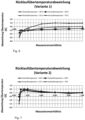
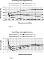
- Figure 8 shows the accuracy of the calculated radiator output in deviation from measured values.
- Q ⁇ Q ⁇ N m ⁇ m ⁇ N ⁇ VL ⁇ ⁇ RL N ⁇ ⁇ VL ⁇ ⁇ Kunststoff ⁇ ⁇ VL ⁇ ⁇ Kunststoff 1 ⁇ y + ⁇ RL ⁇ ⁇ Kunststoff 1 ⁇ y ⁇ ⁇ VL ⁇ ⁇ Kunststoff 1 ⁇ y N ⁇ m ⁇ N m ⁇ 1 1 ⁇ y
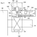
- the radiator control valve 150 has a dynamic valve base 151 that keeps the pressure difference ⁇ p of a heating medium across the radiator control valve 150 constant, regardless of the heating medium flow ⁇ flowing through the radiator control valve 150.
- a dynamic valve base 151 that keeps the pressure difference ⁇ p of a heating medium across the radiator control valve 150 constant, regardless of the heating medium flow ⁇ flowing through the radiator control valve 150.
- Such valves with dynamic valve bases are known in the prior art.
- the radiator control valve 150 is arranged in the inlet connection 61 of a radiator 60, also referred to as the supply connection.
- the heating medium flow ⁇ is adjusted via a valve stem 152, which is displaced in a known manner by a thermostatic head 153 of the radiator control valve 150 in accordance with the room temperature to be regulated in the valve base 151 in order to change the valve flow.
- the thermostatic head 153 has a mimic 160, which, in the case of a conventional mechanical thermostatic head 153 shown here, has a gas, wax, liquid cartridge 161 or similar device that changes its expansion depending on the temperature and is connected to the valve stem 152, so that it adjusts the valve stem 152 depending on the temperature.
- the gas, wax, liquid cartridge 161 itself can be mechanically adjusted by a temperature selection device 162, for example, to preselect a desired room temperature by rotating the thermostatic head 153 in a known manner.
- the heat cost allocator 100 is fastened according to the invention in the area of the conventional thermostatic head 153 and the valve base 151, also referred to as the valve housing, at the inlet connection 61 of the radiator 60.
- the heat cost allocator 100 is received between the valve base 151 and the thermostatic head 153 in such a way that the valve tappet 152 extends through the heat cost allocator 100.
- this is a preferred arrangement because it allows the valve stroke position h to be measured directly in the heat cost allocator 100, other arrangements are also conceivable, for example with an external position sensor or a position sensor integrated into the radiator control valve, which is operated (i.e. supplied with energy and read) via an interface, for example.
- the heat cost allocator 100 (as well as all other described heat cost allocators) can have a radio communication unit (not shown) for communication in a local building network for reading consumption costs and/or for remote communication with a consumption service provider, for example by means of mobile radio communication.
- a radio communication unit (not shown) for communication in a local building network for reading consumption costs and/or for remote communication with a consumption service provider, for example by means of mobile radio communication.
- the heat cost allocator 100 further comprises a flow temperature sensor 101 for measuring the flow temperature ⁇ VL of the heat transfer medium, a room air temperature sensor 102 for measuring the room flow temperature ⁇ Jardin and a device 103 for determining a valve stroke position h of the radiator control valve 150.
- the room air temperature sensor 102 preferably comprises a sensor arranged on the inside of the front side of the housing.
- the flow temperature sensor 101 can, for example, be a wired contact sensor on the valve housing (i.e., the valve base 151) or a sensor arranged on the valve stem 152, as in Fig. 2 shown.
- the device 103 for determining the valve stroke position h measures the stroke h of the valve tappet 152, which was set by the thermostatic head 153, with a position sensor 104.
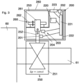
- the variant of the heat cost allocator 200 with radiator control valve 250 has an identical valve base 251 with valve stem 252 in terms of structure and arrangement.
- the thermostatic head 253 and the actuator 260 which includes a gas, wax, or liquid cartridge, and the temperature selection device 262, are also fundamentally identical in structure.
- the components of the heat cost allocator 200 i.e. in particular the flow temperature sensor 201, the room air temperature sensor 202, the device 203 for determining the valve stroke position h with the position sensor 204, the power supply 220 of the heat cost allocator 200, the computing unit 221, the circuit board 222 and the display device 223, are arranged such that the heat cost allocator 200 and the thermostat head 253 are arranged in a common housing 280.
- the housing 280 is preferably constructed rotationally symmetrically around the valve stem 252 so that the mechanical thermostat head 253 can be adjusted in the usual way to set the desired room temperature.
- the advantage of the two previously described variants with a mechanically operated thermostatic head 153, 253 of the radiator control valve 150, 250 is the energy-free temperature control by the radiator control valve 150, 250.
- a power supply (power supply 120, 220) is only required and used for the measurement, calculation, communication, and display functions of the heat cost allocator 100, 200.
- Temperature control by the mechanical thermostatic head 153, 253 does not require a battery.
- the actuator 160, 260 of the mechanical thermostat head 153, 253 can be combined with an electric setpoint adjustment drive. While the room temperature continues to be controlled conventionally and without external energy to the specified setpoint, the setpoint adjustment drive adjusts the setpoint at specified times, thus lowering it, for example, when a night-time setback is activated.
- This can be easily achieved using an electric motor-driven actuator for the temperature selection device 162, 262, which can be controlled, for example, by the processing unit 121, 221 of the heat cost allocator 100, 200 and its power supply 220, 221.
- the display device 123 223, which is used to display consumption values and, if applicable, other values or data of the heat cost allocator 100, 200 and which usually also has function keys, e.g., for switching between the display of various data or for activating the display, can also be used for operating and programming the setback times according to a time profile.
- this pure lowering function for the room temperature can be realized cost-effectively.
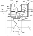
- Fig. 4 finally shows a further embodiment of the invention with an electronic room temperature control in the radiator control valve 350.
- the heat cost allocator 300 with radiator control valve 350 proposed according to this embodiment variant has, instead of a mechanical thermostatic head with the conventional control insert (gas, wax, liquid cartridge), a thermostatic head 353 with an electronic room temperature controller 360 with actuator 361, which replaces the mimic 160, 260 of the mechanical thermostatic head 153, 253 of the previous embodiments.
- the radiator control valve 350 with the dynamic valve base 351 and the valve stem 352 is constructed in a comparable manner.
- the heat cost allocator 300 and the thermostat head 353 are arranged in a common housing 380.
- a particularly advantageous embodiment is the possibility of using the device 303 present in the heat cost allocator 300 for determining the valve stroke position h with the position sensor 304 or a stroke setpoint used in the electronic room temperature controller 360.
- the temperature sensors present for the heat cost allocator function can then be used equally for the control function of the electronic room temperature controller 360. This also results in a compact device without separate sensors.
- the electronic room temperature controller 360 can be integrated into the computing unit 321, which then controls the actuator 361.
- the higher energy requirement compared to the mechanical thermostat head can be covered by a larger battery capacity of the power supply 320, by a replaceable battery or batteries, or by obtaining ambient energy (energy harvesting, e.g. thermally from the heating medium or the surface temperatures).
- radiator or room temperature controller 360 requires a relatively high power and therefore currents for a short time period for the control function of the actuator 361 to regulate the heating medium flow ⁇ , but can manage with little or no power supply during non-heating operating times.
- the heat cost allocator 300 must typically be continuously active for long periods of time, but requires only a low power supply, so that operation, including radio communication, over typical operating times of 10 years from a relatively small battery is common. It may therefore be sensible to operate the actuator with a replaceable battery or with energy harvesting (e.g. a Peltier element), while the heat cost allocation function and the communication and other functions are powered by a permanent battery.
- the Fig. 4 The variant of the embodiment of the heat cost allocator 300 with the radiator control valve 350 shown shows an electronic room temperature controller 360 that is separate from the computing unit 321 of the heat cost allocator 300 and optionally also has a separate display and operating unit as a display device 323. Furthermore, for the functions of the room temperature controller 360, including the operation of the actuator 361, a separate power supply 362 for the radiator control valve 350 is provided, which is equipped with user-replaceable batteries.
- the heat cost allocator 300 with the radiator control valve 350 and the electronic room temperature controller 360 is provided in such a way that the heat cost allocator with the components necessary for heat cost distribution (as described) is provided in an encapsulated part of the housing (corresponding to the representation of the heat cost allocator 350), wherein the encapsulated part is part of the common housing 380.
- a communication connection is provided between the computing unit 321 of the heat cost allocator 300 and the electronic room temperature control 360 of the radiator control valve 350 via an undesignated interface.
- This allows the mono- or bidirectional exchange of data between the radiator control valve 350 and the heat cost allocator 300, whereby the heat cost allocator also remains autonomously functional and protected against tampering.
- the display device 323 may also be omitted due to a display device integrated into the room temperature controller 360.
- the system proposed by the invention consisting of a combined heat cost allocator and radiator control valve (preferably including a room temperature controller), meets the regulatory requirements (Heiz dealtV / EnEV / EED) and is eligible for approval according to EN 834. Therefore, full heat cost allocator functionality is achieved with ease of use, because the system looks and can be used like a conventional or electronic thermostatic valve. Due to its universal design and technical concept, the system is also suitable for surface heating systems, serially flowing multi-layer radiators, and radiators with variable operating characteristics (e.g. additional thermostatic activation or activation of individual or several layers).
Landscapes
- Engineering & Computer Science (AREA)
- Physics & Mathematics (AREA)
- Chemical & Material Sciences (AREA)
- Combustion & Propulsion (AREA)
- Thermal Sciences (AREA)
- Mechanical Engineering (AREA)
- General Engineering & Computer Science (AREA)
- General Physics & Mathematics (AREA)
- Remote Sensing (AREA)
- Automation & Control Theory (AREA)
- Steam Or Hot-Water Central Heating Systems (AREA)
- Temperature-Responsive Valves (AREA)
Priority Applications (1)
| Application Number | Priority Date | Filing Date | Title |
|---|---|---|---|
| PL19154512.8T PL3524951T5 (pl) | 2018-02-13 | 2019-01-30 | Podzielnik kosztów ogrzewania do rejestracji ilości ciepła oddawanej przez grzejnik |
Applications Claiming Priority (1)
| Application Number | Priority Date | Filing Date | Title |
|---|---|---|---|
| DE102018103144.0A DE102018103144A1 (de) | 2018-02-13 | 2018-02-13 | Heizkostenverteiler zur Erfassung der durch einen Heizkörper abgegebenen Wärmemenge |
Publications (3)
| Publication Number | Publication Date |
|---|---|
| EP3524951A1 EP3524951A1 (de) | 2019-08-14 |
| EP3524951B1 EP3524951B1 (de) | 2021-03-24 |
| EP3524951B2 true EP3524951B2 (de) | 2025-03-26 |
Family
ID=65268816
Family Applications (1)
| Application Number | Title | Priority Date | Filing Date |
|---|---|---|---|
| EP19154512.8A Active EP3524951B2 (de) | 2018-02-13 | 2019-01-30 | Heizkostenverteiler zur erfassung der durch einen heizkörper abgegebenen wärmemenge |
Country Status (5)
| Country | Link |
|---|---|
| EP (1) | EP3524951B2 (pl) |
| DE (1) | DE102018103144A1 (pl) |
| DK (1) | DK3524951T4 (pl) |
| ES (1) | ES2878139T5 (pl) |
| PL (1) | PL3524951T5 (pl) |
Families Citing this family (4)
| Publication number | Priority date | Publication date | Assignee | Title |
|---|---|---|---|---|
| DE102021203000B4 (de) * | 2021-03-26 | 2023-01-19 | Qundis Gmbh | Verfahren zum Betrieb einer Heizkostenverteilervorrichtung und Heizkostenverteilervorrichtung |
| DE102021203001B4 (de) | 2021-03-26 | 2023-01-19 | Qundis Gmbh | Verfahren zum Betrieb einer Heizkostenverteilervorrichtung und Heizkostenverteilervorrichtung |
| AT526287A1 (de) * | 2022-06-27 | 2024-01-15 | Purmo Group Plc | Energiemessung von Heizkörpern |
| DE102024205282A1 (de) * | 2024-06-07 | 2025-12-11 | Viessmann Holding International GmbH | Verfahren zum Betrieb eines Smarthome-Systems |
Family Cites Families (7)
| Publication number | Priority date | Publication date | Assignee | Title |
|---|---|---|---|---|
| DE3301422A1 (de) | 1983-01-18 | 1983-09-08 | Johann-Marius Dipl.-Ing. 8520 Erlangen Milosiu | Heizkostenverteiler mit elektrischer messgroessenfassung im kompaktgehaeuse |
| DE3644966A1 (de) * | 1986-12-19 | 1988-06-30 | Gentischer Josef Dipl Ing Fh | Anordnung zur waermeverbrauchsmessung an warmwasser-heizungsanlagen |
| DE102007059253A1 (de) | 2007-12-07 | 2009-06-10 | Ista International Gmbh | Verfahren und Vorrichtung zur Erfassung der Wärmeabgabe einer Heizfläche |
| DE102010033428B4 (de) | 2010-08-04 | 2024-04-18 | Micropelt Gmbh | Heizkörperventil mit Steuerung für ein Stellglied und Heizungssteuerung |
| DE102015121418B3 (de) | 2015-12-09 | 2017-03-16 | Oventrop Gmbh & Co. Kg | Verfahren zum automatischen hydraulischen Abgleich von Verbrauchern in einer Heizungs- und/oder Kühlanlage |
| DE102016104204A1 (de) | 2016-03-08 | 2017-09-14 | Techem Energy Services Gmbh | Vorrichtung und Verfahren zur Ermittlung des Betriebszustands eines Heizkörpers mit einem Heizkörperregelventil |
| DE102016104225A1 (de) * | 2016-03-08 | 2017-09-14 | Techem Energy Services Gmbh | Heizkostenverteiler und Verfahren zur Erfassung der durch einen Heizkörper abgegebenen Wärmemenge |
-
2018
- 2018-02-13 DE DE102018103144.0A patent/DE102018103144A1/de not_active Withdrawn
-
2019
- 2019-01-30 ES ES19154512T patent/ES2878139T5/es active Active
- 2019-01-30 PL PL19154512.8T patent/PL3524951T5/pl unknown
- 2019-01-30 EP EP19154512.8A patent/EP3524951B2/de active Active
- 2019-01-30 DK DK19154512.8T patent/DK3524951T4/da active
Also Published As
| Publication number | Publication date |
|---|---|
| DE102018103144A1 (de) | 2019-08-14 |
| DK3524951T3 (da) | 2021-06-21 |
| ES2878139T5 (en) | 2025-07-10 |
| EP3524951B1 (de) | 2021-03-24 |
| PL3524951T5 (pl) | 2025-07-28 |
| PL3524951T3 (pl) | 2021-10-18 |
| EP3524951A1 (de) | 2019-08-14 |
| DK3524951T4 (da) | 2025-06-23 |
| ES2878139T3 (es) | 2021-11-18 |
Similar Documents
| Publication | Publication Date | Title |
|---|---|---|
| EP3524951B2 (de) | Heizkostenverteiler zur erfassung der durch einen heizkörper abgegebenen wärmemenge | |
| EP3217157B1 (de) | Heizkostenverteiler und verfahren zur erfassung der durch einen heizkörper abgegebenen wärmemenge | |
| EP3376122B1 (de) | Verfahren und vorrichtung zur erfassung der wärmeabgabe eines heizkörpers | |
| DE60119531T2 (de) | Programmierbare brauchwasserheizanlage | |
| EP1936290B1 (de) | Verfahren und Vorrichtung zur Detektion des hydraulischen Zustands einer Heizungsanlage | |
| EP1645928B1 (de) | Verfahren zur Bestimmung eines Heizflächen-Versorgungszustands und Versorgungszustandsregler | |
| EP1770469A2 (de) | Verfahren und System zur Bestimmung von Wärmekenndaten eines Heizkörpers | |
| EP2420748A2 (de) | Verfahren und System zur Durchführung eines hydraulischen Abgleichs in einem Heizungssystem | |
| DE102012023848A1 (de) | Verfahren und Vorrichtung zur Vereinfachung des hydraulischen Abgleichs von fluiddurchströmten Leitungsnetzen | |
| EP2009536B1 (de) | Verfahren und Vorrichtung zur Einstellung der Heizleistungsreserve | |
| EP2068138B1 (de) | Verfahren und Vorrichtung zur Erfassung der Wärmeabgabe einer Heizfläche | |
| DE3529257A1 (de) | Verfahren und anordnung zur ermittlung der waermeabgabe von heizflaechen einer heizungsanlage | |
| EP3599583A1 (de) | Bestimmung des verbrauchs an heiz- oder kühlenergie einer baulichen untereinheit | |
| EP2327971B1 (de) | Verfahren zur Analyse der Wärmemengenverteilung in einem Heizsystem und Vorrichtung zur Durchführung des Verfahrens | |
| EP1235131A2 (de) | Raumtemperaturregelung | |
| EP1235130B1 (de) | Verfahren und Vorrichtung zur Regelung der Raumtemperatur | |
| EP1777465A2 (de) | Verfahren zur Bestimmung des Heizwärmebedarfs eines Gebäudes | |
| EP3168540A1 (de) | Verfahren zum durchführen eines automatisierten hydraulischen abgleichs, ventil und heizungsanlage hierzu | |
| DE102004044106B3 (de) | Heizkostenverteiler | |
| EP3336500B1 (de) | Elektronisches gerät und verfahren zur hybriden wärme- und kältemengenverteilung über standardheizflächen | |
| DE102021203000B4 (de) | Verfahren zum Betrieb einer Heizkostenverteilervorrichtung und Heizkostenverteilervorrichtung | |
| DE102021203001B4 (de) | Verfahren zum Betrieb einer Heizkostenverteilervorrichtung und Heizkostenverteilervorrichtung | |
| EP2151676A2 (de) | Verfahren zum Betrieb eines elektronischen Heizkostenverteilers und gemäss dem Verfahren betriebener elektronischer Heizkostenverteiler | |
| EP4488789B1 (de) | Regelungssystem für die heizungsanlage eines gebäudes | |
| DE102010024741A1 (de) | Verfahren zum Regeln einer Raumtemperatur sowie eine Messvorrichtung und eine Raumtemperaturregelungsanordnung |
Legal Events
| Date | Code | Title | Description |
|---|---|---|---|
| PUAI | Public reference made under article 153(3) epc to a published international application that has entered the european phase |
Free format text: ORIGINAL CODE: 0009012 |
|
| STAA | Information on the status of an ep patent application or granted ep patent |
Free format text: STATUS: THE APPLICATION HAS BEEN PUBLISHED |
|
| AK | Designated contracting states |
Kind code of ref document: A1 Designated state(s): AL AT BE BG CH CY CZ DE DK EE ES FI FR GB GR HR HU IE IS IT LI LT LU LV MC MK MT NL NO PL PT RO RS SE SI SK SM TR |
|
| AX | Request for extension of the european patent |
Extension state: BA ME |
|
| STAA | Information on the status of an ep patent application or granted ep patent |
Free format text: STATUS: REQUEST FOR EXAMINATION WAS MADE |
|
| 17P | Request for examination filed |
Effective date: 20200212 |
|
| RBV | Designated contracting states (corrected) |
Designated state(s): AL AT BE BG CH CY CZ DE DK EE ES FI FR GB GR HR HU IE IS IT LI LT LU LV MC MK MT NL NO PL PT RO RS SE SI SK SM TR |
|
| RIC1 | Information provided on ipc code assigned before grant |
Ipc: G05D 23/19 20060101ALN20200930BHEP Ipc: F24D 19/10 20060101ALI20200930BHEP Ipc: G01K 17/08 20060101AFI20200930BHEP |
|
| GRAP | Despatch of communication of intention to grant a patent |
Free format text: ORIGINAL CODE: EPIDOSNIGR1 |
|
| STAA | Information on the status of an ep patent application or granted ep patent |
Free format text: STATUS: GRANT OF PATENT IS INTENDED |
|
| RIC1 | Information provided on ipc code assigned before grant |
Ipc: F24D 19/10 20060101ALI20201029BHEP Ipc: G01K 17/08 20060101AFI20201029BHEP Ipc: G05D 23/19 20060101ALN20201029BHEP |
|
| INTG | Intention to grant announced |
Effective date: 20201123 |
|
| RIN1 | Information on inventor provided before grant (corrected) |
Inventor name: KAEHLER, ARNE, DR. Inventor name: KLEIN, JOACHIM |
|
| GRAS | Grant fee paid |
Free format text: ORIGINAL CODE: EPIDOSNIGR3 |
|
| GRAA | (expected) grant |
Free format text: ORIGINAL CODE: 0009210 |
|
| STAA | Information on the status of an ep patent application or granted ep patent |
Free format text: STATUS: THE PATENT HAS BEEN GRANTED |
|
| AK | Designated contracting states |
Kind code of ref document: B1 Designated state(s): AL AT BE BG CH CY CZ DE DK EE ES FI FR GB GR HR HU IE IS IT LI LT LU LV MC MK MT NL NO PL PT RO RS SE SI SK SM TR |
|
| REG | Reference to a national code |
Ref country code: GB Ref legal event code: FG4D Free format text: NOT ENGLISH |
|
| REG | Reference to a national code |
Ref country code: CH Ref legal event code: EP |
|
| REG | Reference to a national code |
Ref country code: IE Ref legal event code: FG4D Free format text: LANGUAGE OF EP DOCUMENT: GERMAN |
|
| REG | Reference to a national code |
Ref country code: DE Ref legal event code: R096 Ref document number: 502019001028 Country of ref document: DE Ref country code: AT Ref legal event code: REF Ref document number: 1374974 Country of ref document: AT Kind code of ref document: T Effective date: 20210415 |
|
| REG | Reference to a national code |
Ref country code: DK Ref legal event code: T3 Effective date: 20210617 |
|
| REG | Reference to a national code |
Ref country code: NL Ref legal event code: FP |
|
| REG | Reference to a national code |
Ref country code: LT Ref legal event code: MG9D |
|
| PG25 | Lapsed in a contracting state [announced via postgrant information from national office to epo] |
Ref country code: NO Free format text: LAPSE BECAUSE OF FAILURE TO SUBMIT A TRANSLATION OF THE DESCRIPTION OR TO PAY THE FEE WITHIN THE PRESCRIBED TIME-LIMIT Effective date: 20210624 Ref country code: GR Free format text: LAPSE BECAUSE OF FAILURE TO SUBMIT A TRANSLATION OF THE DESCRIPTION OR TO PAY THE FEE WITHIN THE PRESCRIBED TIME-LIMIT Effective date: 20210625 Ref country code: FI Free format text: LAPSE BECAUSE OF FAILURE TO SUBMIT A TRANSLATION OF THE DESCRIPTION OR TO PAY THE FEE WITHIN THE PRESCRIBED TIME-LIMIT Effective date: 20210324 Ref country code: HR Free format text: LAPSE BECAUSE OF FAILURE TO SUBMIT A TRANSLATION OF THE DESCRIPTION OR TO PAY THE FEE WITHIN THE PRESCRIBED TIME-LIMIT Effective date: 20210324 Ref country code: BG Free format text: LAPSE BECAUSE OF FAILURE TO SUBMIT A TRANSLATION OF THE DESCRIPTION OR TO PAY THE FEE WITHIN THE PRESCRIBED TIME-LIMIT Effective date: 20210624 |
|
| PG25 | Lapsed in a contracting state [announced via postgrant information from national office to epo] |
Ref country code: SE Free format text: LAPSE BECAUSE OF FAILURE TO SUBMIT A TRANSLATION OF THE DESCRIPTION OR TO PAY THE FEE WITHIN THE PRESCRIBED TIME-LIMIT Effective date: 20210324 Ref country code: RS Free format text: LAPSE BECAUSE OF FAILURE TO SUBMIT A TRANSLATION OF THE DESCRIPTION OR TO PAY THE FEE WITHIN THE PRESCRIBED TIME-LIMIT Effective date: 20210324 Ref country code: LV Free format text: LAPSE BECAUSE OF FAILURE TO SUBMIT A TRANSLATION OF THE DESCRIPTION OR TO PAY THE FEE WITHIN THE PRESCRIBED TIME-LIMIT Effective date: 20210324 |
|
| PG25 | Lapsed in a contracting state [announced via postgrant information from national office to epo] |
Ref country code: LT Free format text: LAPSE BECAUSE OF FAILURE TO SUBMIT A TRANSLATION OF THE DESCRIPTION OR TO PAY THE FEE WITHIN THE PRESCRIBED TIME-LIMIT Effective date: 20210324 Ref country code: EE Free format text: LAPSE BECAUSE OF FAILURE TO SUBMIT A TRANSLATION OF THE DESCRIPTION OR TO PAY THE FEE WITHIN THE PRESCRIBED TIME-LIMIT Effective date: 20210324 Ref country code: CZ Free format text: LAPSE BECAUSE OF FAILURE TO SUBMIT A TRANSLATION OF THE DESCRIPTION OR TO PAY THE FEE WITHIN THE PRESCRIBED TIME-LIMIT Effective date: 20210324 Ref country code: SM Free format text: LAPSE BECAUSE OF FAILURE TO SUBMIT A TRANSLATION OF THE DESCRIPTION OR TO PAY THE FEE WITHIN THE PRESCRIBED TIME-LIMIT Effective date: 20210324 |
|
| REG | Reference to a national code |
Ref country code: ES Ref legal event code: FG2A Ref document number: 2878139 Country of ref document: ES Kind code of ref document: T3 Effective date: 20211118 |
|
| PG25 | Lapsed in a contracting state [announced via postgrant information from national office to epo] |
Ref country code: IS Free format text: LAPSE BECAUSE OF FAILURE TO SUBMIT A TRANSLATION OF THE DESCRIPTION OR TO PAY THE FEE WITHIN THE PRESCRIBED TIME-LIMIT Effective date: 20210724 Ref country code: PT Free format text: LAPSE BECAUSE OF FAILURE TO SUBMIT A TRANSLATION OF THE DESCRIPTION OR TO PAY THE FEE WITHIN THE PRESCRIBED TIME-LIMIT Effective date: 20210726 Ref country code: RO Free format text: LAPSE BECAUSE OF FAILURE TO SUBMIT A TRANSLATION OF THE DESCRIPTION OR TO PAY THE FEE WITHIN THE PRESCRIBED TIME-LIMIT Effective date: 20210324 Ref country code: SK Free format text: LAPSE BECAUSE OF FAILURE TO SUBMIT A TRANSLATION OF THE DESCRIPTION OR TO PAY THE FEE WITHIN THE PRESCRIBED TIME-LIMIT Effective date: 20210324 |
|
| REG | Reference to a national code |
Ref country code: DE Ref legal event code: R026 Ref document number: 502019001028 Country of ref document: DE |
|
| PLBI | Opposition filed |
Free format text: ORIGINAL CODE: 0009260 |
|
| PLAX | Notice of opposition and request to file observation + time limit sent |
Free format text: ORIGINAL CODE: EPIDOSNOBS2 |
|
| 26 | Opposition filed |
Opponent name: ISTA INTERNATIONAL GMBH Effective date: 20211222 Opponent name: MOLNIA, DAVID Effective date: 20211221 |
|
| PG25 | Lapsed in a contracting state [announced via postgrant information from national office to epo] |
Ref country code: AL Free format text: LAPSE BECAUSE OF FAILURE TO SUBMIT A TRANSLATION OF THE DESCRIPTION OR TO PAY THE FEE WITHIN THE PRESCRIBED TIME-LIMIT Effective date: 20210324 |
|
| PG25 | Lapsed in a contracting state [announced via postgrant information from national office to epo] |
Ref country code: SI Free format text: LAPSE BECAUSE OF FAILURE TO SUBMIT A TRANSLATION OF THE DESCRIPTION OR TO PAY THE FEE WITHIN THE PRESCRIBED TIME-LIMIT Effective date: 20210324 |
|
| PG25 | Lapsed in a contracting state [announced via postgrant information from national office to epo] |
Ref country code: IS Free format text: LAPSE BECAUSE OF FAILURE TO SUBMIT A TRANSLATION OF THE DESCRIPTION OR TO PAY THE FEE WITHIN THE PRESCRIBED TIME-LIMIT Effective date: 20210724 |
|
| PLBB | Reply of patent proprietor to notice(s) of opposition received |
Free format text: ORIGINAL CODE: EPIDOSNOBS3 |
|
| PG25 | Lapsed in a contracting state [announced via postgrant information from national office to epo] |
Ref country code: MC Free format text: LAPSE BECAUSE OF FAILURE TO SUBMIT A TRANSLATION OF THE DESCRIPTION OR TO PAY THE FEE WITHIN THE PRESCRIBED TIME-LIMIT Effective date: 20210324 |
|
| REG | Reference to a national code |
Ref country code: BE Ref legal event code: MM Effective date: 20220131 |
|
| PG25 | Lapsed in a contracting state [announced via postgrant information from national office to epo] |
Ref country code: LU Free format text: LAPSE BECAUSE OF NON-PAYMENT OF DUE FEES Effective date: 20220130 |
|
| PG25 | Lapsed in a contracting state [announced via postgrant information from national office to epo] |
Ref country code: BE Free format text: LAPSE BECAUSE OF NON-PAYMENT OF DUE FEES Effective date: 20220131 |
|
| PG25 | Lapsed in a contracting state [announced via postgrant information from national office to epo] |
Ref country code: IE Free format text: LAPSE BECAUSE OF NON-PAYMENT OF DUE FEES Effective date: 20220130 |
|
| GBPC | Gb: european patent ceased through non-payment of renewal fee |
Effective date: 20230130 |
|
| PG25 | Lapsed in a contracting state [announced via postgrant information from national office to epo] |
Ref country code: GB Free format text: LAPSE BECAUSE OF NON-PAYMENT OF DUE FEES Effective date: 20230130 |
|
| APBM | Appeal reference recorded |
Free format text: ORIGINAL CODE: EPIDOSNREFNO |
|
| APBP | Date of receipt of notice of appeal recorded |
Free format text: ORIGINAL CODE: EPIDOSNNOA2O |
|
| APAH | Appeal reference modified |
Free format text: ORIGINAL CODE: EPIDOSCREFNO |
|
| APBU | Appeal procedure closed |
Free format text: ORIGINAL CODE: EPIDOSNNOA9O |
|
| PG25 | Lapsed in a contracting state [announced via postgrant information from national office to epo] |
Ref country code: MK Free format text: LAPSE BECAUSE OF FAILURE TO SUBMIT A TRANSLATION OF THE DESCRIPTION OR TO PAY THE FEE WITHIN THE PRESCRIBED TIME-LIMIT Effective date: 20210324 Ref country code: CY Free format text: LAPSE BECAUSE OF FAILURE TO SUBMIT A TRANSLATION OF THE DESCRIPTION OR TO PAY THE FEE WITHIN THE PRESCRIBED TIME-LIMIT Effective date: 20210324 |
|
| PG25 | Lapsed in a contracting state [announced via postgrant information from national office to epo] |
Ref country code: HU Free format text: LAPSE BECAUSE OF FAILURE TO SUBMIT A TRANSLATION OF THE DESCRIPTION OR TO PAY THE FEE WITHIN THE PRESCRIBED TIME-LIMIT; INVALID AB INITIO Effective date: 20190130 |
|
| PG25 | Lapsed in a contracting state [announced via postgrant information from national office to epo] |
Ref country code: TR Free format text: LAPSE BECAUSE OF FAILURE TO SUBMIT A TRANSLATION OF THE DESCRIPTION OR TO PAY THE FEE WITHIN THE PRESCRIBED TIME-LIMIT Effective date: 20210324 |
|
| PG25 | Lapsed in a contracting state [announced via postgrant information from national office to epo] |
Ref country code: MT Free format text: LAPSE BECAUSE OF FAILURE TO SUBMIT A TRANSLATION OF THE DESCRIPTION OR TO PAY THE FEE WITHIN THE PRESCRIBED TIME-LIMIT Effective date: 20210324 |
|
| PLAB | Opposition data, opponent's data or that of the opponent's representative modified |
Free format text: ORIGINAL CODE: 0009299OPPO |
|
| R26 | Opposition filed (corrected) |
Opponent name: ISTA INTERNATIONAL GMBH Effective date: 20211222 |
|
| PUAH | Patent maintained in amended form |
Free format text: ORIGINAL CODE: 0009272 |
|
| STAA | Information on the status of an ep patent application or granted ep patent |
Free format text: STATUS: PATENT MAINTAINED AS AMENDED |
|
| 27A | Patent maintained in amended form |
Effective date: 20250326 |
|
| AK | Designated contracting states |
Kind code of ref document: B2 Designated state(s): AL AT BE BG CH CY CZ DE DK EE ES FI FR GB GR HR HU IE IS IT LI LT LU LV MC MK MT NL NO PL PT RO RS SE SI SK SM TR |
|
| REG | Reference to a national code |
Ref country code: DE Ref legal event code: R102 Ref document number: 502019001028 Country of ref document: DE |
|
| PGFP | Annual fee paid to national office [announced via postgrant information from national office to epo] |
Ref country code: CH Payment date: 20250201 Year of fee payment: 7 |
|
| PGFP | Annual fee paid to national office [announced via postgrant information from national office to epo] |
Ref country code: PL Payment date: 20250130 Year of fee payment: 7 |
|
| REG | Reference to a national code |
Ref country code: DK Ref legal event code: T4 Effective date: 20250617 |
|
| REG | Reference to a national code |
Ref country code: NL Ref legal event code: FP |
|
| REG | Reference to a national code |
Ref country code: ES Ref legal event code: DC2A Ref document number: 2878139 Country of ref document: ES Kind code of ref document: T5 Effective date: 20250710 |
|
| REG | Reference to a national code |
Ref country code: CH Ref legal event code: U11 Free format text: ST27 STATUS EVENT CODE: U-0-0-U10-U11 (AS PROVIDED BY THE NATIONAL OFFICE) Effective date: 20260201 |
|
| PGFP | Annual fee paid to national office [announced via postgrant information from national office to epo] |
Ref country code: NL Payment date: 20260121 Year of fee payment: 8 |
|
| PGFP | Annual fee paid to national office [announced via postgrant information from national office to epo] |
Ref country code: ES Payment date: 20260217 Year of fee payment: 8 |
|
| PGFP | Annual fee paid to national office [announced via postgrant information from national office to epo] |
Ref country code: DK Payment date: 20260121 Year of fee payment: 8 Ref country code: DE Payment date: 20260120 Year of fee payment: 8 |
|
| PGFP | Annual fee paid to national office [announced via postgrant information from national office to epo] |
Ref country code: AT Payment date: 20260123 Year of fee payment: 8 |
|
| PGFP | Annual fee paid to national office [announced via postgrant information from national office to epo] |
Ref country code: IT Payment date: 20260130 Year of fee payment: 8 |
|
| PGFP | Annual fee paid to national office [announced via postgrant information from national office to epo] |
Ref country code: FR Payment date: 20260121 Year of fee payment: 8 |