EP3524861A1 - Sealing device and sealing assembly - Google Patents
Sealing device and sealing assembly Download PDFInfo
- Publication number
- EP3524861A1 EP3524861A1 EP17858262.3A EP17858262A EP3524861A1 EP 3524861 A1 EP3524861 A1 EP 3524861A1 EP 17858262 A EP17858262 A EP 17858262A EP 3524861 A1 EP3524861 A1 EP 3524861A1
- Authority
- EP
- European Patent Office
- Prior art keywords
- seal portion
- tube
- valve body
- sealing device
- valve
- Prior art date
- Legal status (The legal status is an assumption and is not a legal conclusion. Google has not performed a legal analysis and makes no representation as to the accuracy of the status listed.)
- Withdrawn
Links
Images



Classifications
-
- F—MECHANICAL ENGINEERING; LIGHTING; HEATING; WEAPONS; BLASTING
- F16—ENGINEERING ELEMENTS AND UNITS; GENERAL MEASURES FOR PRODUCING AND MAINTAINING EFFECTIVE FUNCTIONING OF MACHINES OR INSTALLATIONS; THERMAL INSULATION IN GENERAL
- F16J—PISTONS; CYLINDERS; SEALINGS
- F16J15/00—Sealings
- F16J15/16—Sealings between relatively-moving surfaces
- F16J15/34—Sealings between relatively-moving surfaces with slip-ring pressed against a more or less radial face on one member
- F16J15/3464—Mounting of the seal
- F16J15/3472—Means for centering or aligning the contacting faces
-
- F—MECHANICAL ENGINEERING; LIGHTING; HEATING; WEAPONS; BLASTING
- F16—ENGINEERING ELEMENTS AND UNITS; GENERAL MEASURES FOR PRODUCING AND MAINTAINING EFFECTIVE FUNCTIONING OF MACHINES OR INSTALLATIONS; THERMAL INSULATION IN GENERAL
- F16J—PISTONS; CYLINDERS; SEALINGS
- F16J15/00—Sealings
- F16J15/16—Sealings between relatively-moving surfaces
- F16J15/18—Sealings between relatively-moving surfaces with stuffing-boxes for elastic or plastic packings
-
- F—MECHANICAL ENGINEERING; LIGHTING; HEATING; WEAPONS; BLASTING
- F16—ENGINEERING ELEMENTS AND UNITS; GENERAL MEASURES FOR PRODUCING AND MAINTAINING EFFECTIVE FUNCTIONING OF MACHINES OR INSTALLATIONS; THERMAL INSULATION IN GENERAL
- F16J—PISTONS; CYLINDERS; SEALINGS
- F16J15/00—Sealings
- F16J15/16—Sealings between relatively-moving surfaces
- F16J15/32—Sealings between relatively-moving surfaces with elastic sealings, e.g. O-rings
- F16J15/3204—Sealings between relatively-moving surfaces with elastic sealings, e.g. O-rings with at least one lip
-
- F—MECHANICAL ENGINEERING; LIGHTING; HEATING; WEAPONS; BLASTING
- F16—ENGINEERING ELEMENTS AND UNITS; GENERAL MEASURES FOR PRODUCING AND MAINTAINING EFFECTIVE FUNCTIONING OF MACHINES OR INSTALLATIONS; THERMAL INSULATION IN GENERAL
- F16J—PISTONS; CYLINDERS; SEALINGS
- F16J15/00—Sealings
- F16J15/16—Sealings between relatively-moving surfaces
- F16J15/32—Sealings between relatively-moving surfaces with elastic sealings, e.g. O-rings
- F16J15/3204—Sealings between relatively-moving surfaces with elastic sealings, e.g. O-rings with at least one lip
- F16J15/3208—Sealings between relatively-moving surfaces with elastic sealings, e.g. O-rings with at least one lip provided with tension elements, e.g. elastic rings
- F16J15/3212—Sealings between relatively-moving surfaces with elastic sealings, e.g. O-rings with at least one lip provided with tension elements, e.g. elastic rings with metal springs
-
- F—MECHANICAL ENGINEERING; LIGHTING; HEATING; WEAPONS; BLASTING
- F16—ENGINEERING ELEMENTS AND UNITS; GENERAL MEASURES FOR PRODUCING AND MAINTAINING EFFECTIVE FUNCTIONING OF MACHINES OR INSTALLATIONS; THERMAL INSULATION IN GENERAL
- F16J—PISTONS; CYLINDERS; SEALINGS
- F16J15/00—Sealings
- F16J15/16—Sealings between relatively-moving surfaces
- F16J15/32—Sealings between relatively-moving surfaces with elastic sealings, e.g. O-rings
- F16J15/3204—Sealings between relatively-moving surfaces with elastic sealings, e.g. O-rings with at least one lip
- F16J15/3224—Sealings between relatively-moving surfaces with elastic sealings, e.g. O-rings with at least one lip capable of accommodating changes in distances or misalignment between the surfaces, e.g. able to compensate for defaults of eccentricity or angular deviations
-
- F—MECHANICAL ENGINEERING; LIGHTING; HEATING; WEAPONS; BLASTING
- F16—ENGINEERING ELEMENTS AND UNITS; GENERAL MEASURES FOR PRODUCING AND MAINTAINING EFFECTIVE FUNCTIONING OF MACHINES OR INSTALLATIONS; THERMAL INSULATION IN GENERAL
- F16J—PISTONS; CYLINDERS; SEALINGS
- F16J15/00—Sealings
- F16J15/16—Sealings between relatively-moving surfaces
- F16J15/34—Sealings between relatively-moving surfaces with slip-ring pressed against a more or less radial face on one member
- F16J15/3496—Sealings between relatively-moving surfaces with slip-ring pressed against a more or less radial face on one member use of special materials
-
- F—MECHANICAL ENGINEERING; LIGHTING; HEATING; WEAPONS; BLASTING
- F16—ENGINEERING ELEMENTS AND UNITS; GENERAL MEASURES FOR PRODUCING AND MAINTAINING EFFECTIVE FUNCTIONING OF MACHINES OR INSTALLATIONS; THERMAL INSULATION IN GENERAL
- F16K—VALVES; TAPS; COCKS; ACTUATING-FLOATS; DEVICES FOR VENTING OR AERATING
- F16K5/00—Plug valves; Taps or cocks comprising only cut-off apparatus having at least one of the sealing faces shaped as a more or less complete surface of a solid of revolution, the opening and closing movement being predominantly rotary
- F16K5/06—Plug valves; Taps or cocks comprising only cut-off apparatus having at least one of the sealing faces shaped as a more or less complete surface of a solid of revolution, the opening and closing movement being predominantly rotary with plugs having spherical surfaces; Packings therefor
-
- F—MECHANICAL ENGINEERING; LIGHTING; HEATING; WEAPONS; BLASTING
- F16—ENGINEERING ELEMENTS AND UNITS; GENERAL MEASURES FOR PRODUCING AND MAINTAINING EFFECTIVE FUNCTIONING OF MACHINES OR INSTALLATIONS; THERMAL INSULATION IN GENERAL
- F16K—VALVES; TAPS; COCKS; ACTUATING-FLOATS; DEVICES FOR VENTING OR AERATING
- F16K5/00—Plug valves; Taps or cocks comprising only cut-off apparatus having at least one of the sealing faces shaped as a more or less complete surface of a solid of revolution, the opening and closing movement being predominantly rotary
- F16K5/06—Plug valves; Taps or cocks comprising only cut-off apparatus having at least one of the sealing faces shaped as a more or less complete surface of a solid of revolution, the opening and closing movement being predominantly rotary with plugs having spherical surfaces; Packings therefor
- F16K5/0663—Packings
- F16K5/0673—Composite packings
- F16K5/0678—Composite packings in which only one of the components of the composite packing is contacting the plug
-
- F—MECHANICAL ENGINEERING; LIGHTING; HEATING; WEAPONS; BLASTING
- F16—ENGINEERING ELEMENTS AND UNITS; GENERAL MEASURES FOR PRODUCING AND MAINTAINING EFFECTIVE FUNCTIONING OF MACHINES OR INSTALLATIONS; THERMAL INSULATION IN GENERAL
- F16K—VALVES; TAPS; COCKS; ACTUATING-FLOATS; DEVICES FOR VENTING OR AERATING
- F16K5/00—Plug valves; Taps or cocks comprising only cut-off apparatus having at least one of the sealing faces shaped as a more or less complete surface of a solid of revolution, the opening and closing movement being predominantly rotary
- F16K5/08—Details
- F16K5/14—Special arrangements for separating the sealing faces or for pressing them together
- F16K5/20—Special arrangements for separating the sealing faces or for pressing them together for plugs with spherical surfaces
- F16K5/201—Special arrangements for separating the sealing faces or for pressing them together for plugs with spherical surfaces with the housing or parts of the housing mechanically pressing the seal against the plug
Definitions
- the present invention relates to a sealing device for preventing a fluid from leaking from a tube which is connected to a valve box or is a part of the valve box and a valve body by sealing therebetween, and a sealing assembly having such a sealing device.
- Patent Document 1 relates to a refrigerant control valve device and this refrigerant control valve device comprises, as shown in Figure 6 , a valve housing 100 and a valve body 102 that is rotatably disposed about an axis of rotation X in the valve housing 100 and controls the flow of a refrigerant.
- a discharge cylinder 104 is connected to the valve housing 100.
- a sealing mechanism for sealing between the discharge cylinder 104 and the valve body 102 is provided at the connection between the valve housing (valve box) 100 and the discharge cylinder (tube) 104.
- This sealing mechanism has three ring-shaped members: a seal ring 106, a packing body 108, and a support ring 110, centered on the central axis Y of the discharge cylinder 104. Further, the sealing mechanism has a spring 112.
- the seal ring 106 is formed from a resin material and contacts the outer surface of the valve body 102.
- the packing body 108 is formed from a resin material and contacts the outer surface of a sleeve 104A at a tip of the discharge cylinder 104.
- the support ring 110 is constituted by a metal material such as stainless steel.
- the spring 112 applies a biasing force to the seal ring 106 via the support ring 110.
- Patent Document 1 JP 2016-114125 A
- a seal portion preferably constantly closely contacts the outer surface of a valve body, the number of parts of the sealing mechanism is preferably small, and mounting on a valve device is preferably easy.
- the objective of the present invention is to provide a sealing device with high contact of a seal portion to the outer surface of a valve body, a small number of parts, and easy mounting on a valve device, and a sealing assembly comprising such a sealing device.
- the sealing device is characterized by being a sealing device for sealing between a valve body which is movably disposed in a valve box and which controls a flow of a fluid and a tube which is connected to the valve box or is a part of the valve box and through which the fluid flows, comprising a first seal portion that is a resin annular plate or film and is to be closely contacted with the outer surface of the valve body and a cylindrical second seal portion which is formed from a material more flexible than that of the first seal portion, contacts the inner surface or outer surface of the tube, and prevents the fluid from leaking from the tube, wherein the first seal portion and the second seal portion are integrally joined.
- the first seal portion which is a plate or film to be closely contacted with the outer surface of the valve body, and the cylindrical second seal portion, which contacts the inner surface or outer surface of the tube, are integrally joined.
- the second seal portion is formed from a material more flexible than that of the first seal portion, the first seal portion can be contacted to the outer surface of the valve body by pressing the annular first seal portion via the cylindrical second seal portion and contact of the first seal portion to the outer surface of the valve body is high.
- the first seal portion and the second seal portion are integrally joined, so the number of parts is reduced.
- the sealing device is disposed on the inside or outside of a tube, the first seal portion is closely contacted to the outer surface of a valve body by pressing the first seal portion via the second seal portion, and the sealing device may be fixed in this state. Accordingly, mounting on a valve device is easy.
- the entirety of the surface of the first seal portion on the opposite side of the surface to be closely contacted with the outer surface of the valve body is joined to the second seal portion.
- the entirety of the plate-shaped or film-shaped first seal portion is supported by the second seal portion, which is more flexible than the first seal portion. Accordingly, contact of the first seal portion to the outer surface of the valve body is high and even if the outer surface of the valve body is rough, the first seal portion can contact the outer surface of the valve body over a wide surface area. Further, when the valve body moves in the valve box, the first seal portion constantly closely contacts the outer surface of the valve body.
- a flange joined to the first seal portion is formed on an edge of the second seal portion and the flange protrudes inwards in the radial direction of the second seal portion.
- a fluid can flow inside the cylindrical second seal portion.
- the flange protruding inwards in the radial direction of the second seal portion receives high pressure from the fluid in the direction toward the valve body. Due to the flange on the second seal portion receiving such pressure, the first seal portion joined to the flange is also pressed toward the valve body. Accordingly, contact of the first seal portion to the outer surface of the valve body is further increased.
- the sealing assembly comprises the abovementioned sealing device and a pressing mechanism which is fixed to the tube and presses the first seal portion and the second seal portion toward the valve body and closely contacts the first seal portion with the outer surface of the valve body.
- a sealing assembly in mounting a sealing device on a valve device, it is possible for the sealing device to be fixed by disposing the sealing device on the inside or outside of a tube, closely contacting the first seal portion to the outer surface of the valve body by the pressing mechanism pressing the first seal portion via the second seal portion, and fixing the pressing mechanism to the tube in this state. Accordingly, mounting of the sealing device is easy.
- the pressing mechanism comprises a ring that fits into a peripheral groove formed on the inner peripheral surface or the outer peripheral surface of the tube. In this case, it is possible to easily fix the sealing device by fitting the ring in the peripheral groove.
- contact of the first seal portion to the outer surface of the valve body is high. Moreover, the number of parts is reduced. Furthermore, mounting on a valve device is easy.
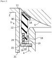
- FIG 1 is a cross-sectional view of part of a sealing assembly 1 according to the first embodiment of the present invention.
- the sealing assembly 1 is applied to a valve device 2, which is similar to the refrigerant control valve device shown in Figure 6 .
- the valve device 2 comprises a valve box 3 (corresponding to valve housing 100 in Figure 6 ), a tube 4 (corresponding to discharge cylinder 104 in Figure 6 ) which is connected to the valve box 3 or is a part of the valve box 3 and through which a fluid flows, and a valve body 6 (corresponding to valve body 102 in Figure 6 ) which is disposed in the valve box 3 and controls a flow of a fluid.
- the valve device 2 to which the sealing assembly 1 is applied may be, for example, a valve device for supplying cooling water (refrigerant) for an internal combustion engine to a radiator, or may be another valve device.
- the fluid controlled by the valve device 2 may be a refrigerant such as cooling water or may be another fluid.
- the illustrated tube 4 is provided downstream of the valve box 3 and the fluid moving through the valve box 3 transits the tube 4, but the tube 4 may be provided upstream of the valve box 3 and the fluid moving through the tube 4 transits the valve box 3.
- valve body 6 can move within the valve box 3, for example, can rotate, and along with this movement, adjusts the flow rate of the fluid transiting the valve device 2.
- valve box 3 and the valve body 6 are only partially shown, but, similar to the valve body 102 in Figure 6 , the valve body 6 is disposed in the valve box 3 and can rotate about the same axis of rotation as axis of rotation X (not illustrated, but extending laterally above the section illustrated in Figure 1 ).
- the sealing assembly 1 has a sealing device 10 for preventing the fluid from leaking from the tube 4 and the valve body 6 by sealing therebetween and a pressing mechanism (a ring 22 and a coil spring 24 in this embodiment) for pressing the sealing device 10 toward the valve body 6.
- the sealing device 10 is approximately circular and engages with the cylindrical tube 4, but only the left-hand portion thereof is shown in Figure 1 . Only the left-hand portions of the ring 22 and the coil spring 24 are shown as well.
- the sealing device 10 has a first seal portion 11 which is an annular resin plate or film and a cylindrical second seal portion 12 formed from a material more flexible than that of the first seal portion 11.
- the first seal portion 11 is formed from, for example, polytetrafluoroethylene (PTFE).
- the second seal portion 12 is formed from an elastic body, for example, an elastomer.
- the first seal portion 11 is to be closely contacted with the outer surface of the valve body 6.
- the second seal portion 12 is disposed inside the tube 4, contacts the inner peripheral surface of the tube 4, and prevents fluid from leaking from the tube 4.
- the sealing device 10 seals such that the fluid transiting the valve body 6 and the tube 4 does not leak.
- the first seal portion 11 and the second seal portion 12 are integrally joined.
- the technique for integration is arbitrary and may be, for example, adhering with an adhesive, or the first seal portion 11 and the second seal portion 12 may be bonded by making use of crosslinking of the material of the second seal portion 12.
- a flange 14 is formed on the edge of the second seal portion 12 on the valve body 6 side and the flange 14 protrudes inwards in the radial direction of the second seal portion 12.
- the entirety of the surface of the first seal portion 11 on the opposite side of the surface to be closely contacted with the outer surface of the valve body 6 is joined to the flange 14 of the second seal portion 12.
- a peripheral groove 20 is formed on the inner peripheral surface of the tube 4 and the ring 22, preferably a snap ring, fits into the peripheral groove 20.
- the ring 22 is fixed to the tube 4 and presses the second seal portion 12 and the first seal portion 11 toward the valve body 6, constituting a pressing mechanism for closely contacting the first seal portion 11 with the outer surface of the valve body 6.
- the inner diameter of the ring 22 is set to a size with minimal disruption of the flow of the fluid in the tube 4.
- the pressing mechanism further has a coil spring 24.
- the coil spring 24 is disposed between the ring 22 and the second seal portion 12 and presses the sealing device 10 toward the valve body 6 via the restoring force thereof.
- a cutout into which the coil spring 24 fits is formed on an edge 16 of the second seal portion 12 on the opposite side of the first seal portion 11.
- a lip that is, a protrusion 18 for contacting the inner peripheral surface of the tube 4 across the entire periphery is formed on the peripheral external surface of the second seal portion 12 facing the tube 4.
- the protrusion 18 is an annular thin plate continuous in the circumferential direction, supported by the edge 16 of the second seal portion 12 on the inward radial side, and extending toward the free end on the outward radial side. The free end of the protrusion 18 is in contact with the inner peripheral surface of the tube 4 across the entire periphery.
- the protrusion 18 Upon receiving pressure from the fluid in the tube 4, the protrusion 18 is strongly pushed against the inner peripheral surface of the tube 4, such that the function of sealing the fluid increases.
- the protrusion 18 is in contact with the inner peripheral surface of the tube 4 even when not receiving pressure from the fluid in the tube 4.
- the protrusion 18 may be modified so that the protrusion 18 does not contact the tube 4 when not receiving pressure from the fluid in the tube 4 and the protrusion 18 contacts the inner peripheral surface of the tube 4 across the entire periphery due to elastic deformation upon receiving pressure from the fluid in the tube 4.
- the sealing device 10 in mounting the sealing device 10 on the valve device 2, it is possible to dispose the second seal portion 12 inside the tube 4 in a state in which the second seal portion 12 does not contact the tube 4 and there is little frictional resistance.
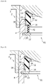
- the sealing device 10 In mounting the sealing device 10 on the valve device 2, as shown in Figure 2 , the sealing device 10 is disposed inside the tube 4 and the first seal portion 11 is made to contact the outer surface of the valve body 6. In this state, a large portion of the flange 14 of the second seal portion 12 extends diagonally upwards from the edge of the outer side of the flange 14 in the illustration.
- the first seal portion 11 to be closely contacted with the outer surface of the valve body 6 and the second seal portion 12 that contacts the inner surface of the tube 4 are integrally joined.
- the second seal portion 12 is formed from a material more flexible than that of the first seal portion 11, so the first seal portion 11 can be contacted to the outer surface of the valve body 6 by pressing the annular first seal portion 11 via the cylindrical second seal portion 11 and contact of the first seal portion 11 to the outer surface of the valve body 6 is high. Further, the entirety of the plate-shaped or film-shaped first seal portion 11 is supported by the second seal portion 12, which is more flexible than the first seal portion 11.
- the first seal portion 11 contact of the first seal portion 11 to the outer surface of the valve body 6 is high and, even if the outer surface of the valve body 6 is rough, it is possible for the first seal portion 11 to contact the outer surface of the valve body 6 over a wide surface area. Further, when the valve body 6 moves in the valve box 3, the first seal portion 11 constantly closely contacts the outer surface of the valve body 6.
- the fluid can flow inside the cylindrical second seal portion 12.
- the flange 14 protruding in the radial inner direction of the second seal portion 12 receives high pressure from the fluid in the direction toward the valve body 6. Due to the flange 14 of the second seal portion 12 receiving such pressure, the first seal portion 11 joined to the flange 14 is also pressed toward the valve body 6. Accordingly, contact of the first seal portion 11 to the outer surface of the valve body 6 is further increased.
- the first seal portion 11 and the second seal portion 12 are integrally joined, so the number of parts is reduced. Accordingly, in mounting on the valve device 2, labor such as searching for parts and confirming the disposal direction can be reduced.
- the sealing device 10 in mounting the sealing device 10 on the valve device 2, it is possible to fix the sealing device 10 by disposing the sealing device 10 inside the tube 4, closely contacting the first seal portion 11 to the outer surface of the valve body 6 by the pressing mechanism pressing the first seal portion 11 via the second seal portion 12, and fixing the pressing mechanism to the tube 4 in this state. Accordingly, mounting the sealing device 10 is easy.
- the pressing mechanism comprises the ring 22 which fits into the peripheral groove 20 formed on the inner peripheral surface of the tube 4, so it is possible to easily fix the sealing device 10 by fitting the ring 22 in the peripheral groove 20 of the tube 4.
- the ring 22 is a snap ring, the ring 22 is not continuous over the entire periphery, so the amount of deformation of the ring 22 is large and it is possible to easily fit the ring 22 in the peripheral groove 20 of the tube 4.
- the protrusion 18 formed on the second seal portion 12 contacts the tube 4 across the entire periphery and is strongly pressed against the inner surface of the tube 4 upon receiving pressure from the fluid, so contact of the second seal portion 12 to the tube 4 is increased.
- the second seal portion 12 is eccentric with respect to the tube 4, close contact of the second seal portion 12 to the tube 4 by the protrusion 18 is reliable.
- the outer diameter of the second seal portion 12 is set smaller than the inner diameter of the tube 4. Therefore, in mounting the sealing device 10 on the valve device 2, it is possible to dispose the second seal portion 12 inside the tube 4 in a state with little frictional resistance by avoiding contacting the second seal portion 12, excluding the protrusion 18, with the tube 4.
- FIG. 3 shows a sealing assembly 31 according to the second embodiment of the present invention.
- the same reference numbers are used to indicate components shared with the first embodiment and these components will not be explained in detail.
- the sealing assembly 31 has a sealing device 30 for preventing fluid from leaking from the tube 4 and the valve body 6 by sealing therebetween and a pressing mechanism (the ring 22 and the coil spring 24 in this embodiment) for pressing the sealing device 30 toward the valve body 6.
- the sealing device 10 and the coil spring 24 are disposed inside the tube 4 in the first embodiment, whereas the sealing device 30 and the coil spring 24 are disposed outside the tube 24 in the second embodiment. Accordingly, in this embodiment, the peripheral groove 20 is formed on the outer peripheral surface of the tube 4 and the ring 22, preferably a snap ring, fits into the peripheral groove 20.
- a lip that is, the protrusion 18 for contacting the outer peripheral surface of the tube 4 across the entire periphery is formed on the inner peripheral surface of the second seal portion 12 facing the tube 4.
- the protrusion 18 is an annular thin plate continuous in the circumferential direction, supported by the edge 16 of the second seal portion 12 on the outward radial side, and extending toward the free end on the radial outward side. The free end of the protrusion 18 contacts the outer peripheral surface of the tube 4 over the entire periphery.
- the protrusion 18 Upon receiving pressure from the fluid in the tube 4, the protrusion 18 is strongly pressed against the outer peripheral surface of the tube 4 such that the function of sealing the fluid increases.
- the protrusion 18 contacts the outer peripheral surface of the tube 4 even when not receiving pressure from the fluid in the tube 4.
- the protrusion 18 may be modified so that the protrusion 18 does not contact the tube 4 when not receiving pressure from the fluid in the tube 4 and the protrusion 18 contacts the outer peripheral surface of the tube 4 across the entire periphery due to elastic deformation upon receiving pressure from the fluid in the tube 4.
- the sealing device 10 in mounting the sealing device 10 on the valve device 2, it is possible to dispose the second seal portion 12 outside the tube 4 in a state in which the second seal portion 12 does not contact the tube 4 and there is little frictional resistance.
- the sealing device 30 In the mounting of the sealing device 30 on the valve device 2, the sealing device 30 is disposed on the outside of the tube 4 and the first seal portion 11 is made to contact the outer surface of the valve body 6.
- the entirety of the outer surface of the first seal portion 11 is closely contacted to the outer surface of the valve body 6 by pressing the first seal portion 11 via the coil spring 24 and the second seal portion 12.
- the ring 22 can be fit into the peripheral groove 20 of the tube 4 and the sealing device 30 fixed.
- the inner diameter of the second seal portion 12 (locations excluding the flange 14 among the locations of the second seal portion 12 which have the possibility of approaching the outer peripheral surface of the tube 4) is set larger than the outer diameter of the tube 4. Therefore, in mounting the sealing device 10 on the valve device 2, it is possible to dispose the second seal portion 12 outside the tube 4 in a state with little frictional resistance by avoiding contacting the second seal portion 12, excluding the protrusion 18, with the tube 4.
- FIG. 4 shows a sealing assembly 41 according to the third embodiment of the present invention.
- the sealing assembly 41 has a sealing device 10 which is the same as that in the first embodiment and a pressing mechanism (in this embodiment, the ring 22 and a cylindrical elastic body 42) for pressing the sealing device 10 toward the valve body 6.
- the cylindrical elastic body 42 is provided in place of the coil spring 24.
- the cylindrical elastic body 42 is formed from, for example, an elastomer.
- the cylindrical elastic body 42 is disposed between the ring 22 and the second seal portion 12 and presses the sealing device 10 toward the valve body 6 via the restoring force thereof.
- a cutout into which the cylindrical elastic body 42 fits is formed on the edge 16 of the second seal portion 12 on the opposite side of the first seal portion 11.
- the cylindrical elastic body 42 may be provided in place of the coil spring 42 in the second embodiment ( Figure 3 ).
- FIG. 5 shows a sealing assembly 51 according to the fourth embodiment of the present invention.
- the sealing assembly 51 has a sealing device 50 similar to the sealing device 10 of the first embodiment and a pressing mechanism (in this embodiment, only the ring 22) for pressing the sealing device 50 toward the valve body 6.
- the sealing device 50 is pressed toward the valve body 6 only by the ring 22 fit into the peripheral groove 20 on the inner peripheral surface of the tube 4, without providing the coil spring 24 or the cylindrical elastic body 42.
- the second seal portion 12 of the sealing device 50 is an elastic body and is compressed between the ring 22 and the valve body 6. Due to the restoring force of the second seal portion 12, the first seal portion 11 of the sealing device 50 is pressed toward the valve body 6.
- the valve body 6 has an outer surface similar to a part of a sphere.
- the valve body 6 may be cylindrical.
- the sealing device would be modified so as to have a shape and dimensions in accordance with the shape of the outer surface of the valve body 6 such that the first seal portion 11 closely contacts the outer surface of the valve body 6.
- a valve device comprising a valve box connected to a tube through which a fluid flows or having the tube, a valve body that is movably disposed in the valve box and controls flowing of the fluid, and a sealing device according to the present invention for sealing between the valve body and the tube is also an aspect of the present invention.
Landscapes
- Engineering & Computer Science (AREA)
- General Engineering & Computer Science (AREA)
- Mechanical Engineering (AREA)
- Gasket Seals (AREA)
- Valve Housings (AREA)
- Taps Or Cocks (AREA)
- Sealing Devices (AREA)
Abstract
Description
- The present invention relates to a sealing device for preventing a fluid from leaking from a tube which is connected to a valve box or is a part of the valve box and a valve body by sealing therebetween, and a sealing assembly having such a sealing device.
- Conventionally, as a sealing mechanism for sealing between a tube connected to a valve box and a valve body there is, for example, the invention disclosed in Patent Document 1. Patent Document 1 relates to a refrigerant control valve device and this refrigerant control valve device comprises, as shown in
Figure 6 , avalve housing 100 and avalve body 102 that is rotatably disposed about an axis of rotation X in thevalve housing 100 and controls the flow of a refrigerant. Adischarge cylinder 104 is connected to thevalve housing 100. - A sealing mechanism for sealing between the
discharge cylinder 104 and thevalve body 102 is provided at the connection between the valve housing (valve box) 100 and the discharge cylinder (tube) 104. This sealing mechanism has three ring-shaped members: aseal ring 106, apacking body 108, and asupport ring 110, centered on the central axis Y of thedischarge cylinder 104. Further, the sealing mechanism has aspring 112. - The
seal ring 106 is formed from a resin material and contacts the outer surface of thevalve body 102. Thepacking body 108 is formed from a resin material and contacts the outer surface of asleeve 104A at a tip of thedischarge cylinder 104. Thesupport ring 110 is constituted by a metal material such as stainless steel. Thespring 112 applies a biasing force to theseal ring 106 via thesupport ring 110. - Patent Document 1:
JP 2016-114125 A - In this type of sealing mechanism, a seal portion preferably constantly closely contacts the outer surface of a valve body, the number of parts of the sealing mechanism is preferably small, and mounting on a valve device is preferably easy.
- Thus, the objective of the present invention is to provide a sealing device with high contact of a seal portion to the outer surface of a valve body, a small number of parts, and easy mounting on a valve device, and a sealing assembly comprising such a sealing device.
- To solve the abovementioned problem, the sealing device according to the present invention is characterized by being a sealing device for sealing between a valve body which is movably disposed in a valve box and which controls a flow of a fluid and a tube which is connected to the valve box or is a part of the valve box and through which the fluid flows, comprising a first seal portion that is a resin annular plate or film and is to be closely contacted with the outer surface of the valve body and a cylindrical second seal portion which is formed from a material more flexible than that of the first seal portion, contacts the inner surface or outer surface of the tube, and prevents the fluid from leaking from the tube, wherein the first seal portion and the second seal portion are integrally joined.
- In the sealing device according to the present invention, the first seal portion, which is a plate or film to be closely contacted with the outer surface of the valve body, and the cylindrical second seal portion, which contacts the inner surface or outer surface of the tube, are integrally joined. As the second seal portion is formed from a material more flexible than that of the first seal portion, the first seal portion can be contacted to the outer surface of the valve body by pressing the annular first seal portion via the cylindrical second seal portion and contact of the first seal portion to the outer surface of the valve body is high. The first seal portion and the second seal portion are integrally joined, so the number of parts is reduced. Furthermore, in mounting on a valve device, the sealing device is disposed on the inside or outside of a tube, the first seal portion is closely contacted to the outer surface of a valve body by pressing the first seal portion via the second seal portion, and the sealing device may be fixed in this state. Accordingly, mounting on a valve device is easy.
- In the sealing device in one aspect of the present invention, the entirety of the surface of the first seal portion on the opposite side of the surface to be closely contacted with the outer surface of the valve body is joined to the second seal portion. In this case, the entirety of the plate-shaped or film-shaped first seal portion is supported by the second seal portion, which is more flexible than the first seal portion. Accordingly, contact of the first seal portion to the outer surface of the valve body is high and even if the outer surface of the valve body is rough, the first seal portion can contact the outer surface of the valve body over a wide surface area. Further, when the valve body moves in the valve box, the first seal portion constantly closely contacts the outer surface of the valve body.
- In the sealing device in one aspect of the present invention, a flange joined to the first seal portion is formed on an edge of the second seal portion and the flange protrudes inwards in the radial direction of the second seal portion. A fluid can flow inside the cylindrical second seal portion. At this time, the flange protruding inwards in the radial direction of the second seal portion receives high pressure from the fluid in the direction toward the valve body. Due to the flange on the second seal portion receiving such pressure, the first seal portion joined to the flange is also pressed toward the valve body. Accordingly, contact of the first seal portion to the outer surface of the valve body is further increased.
- The sealing assembly according to the present invention comprises the abovementioned sealing device and a pressing mechanism which is fixed to the tube and presses the first seal portion and the second seal portion toward the valve body and closely contacts the first seal portion with the outer surface of the valve body. According to such a sealing assembly, in mounting a sealing device on a valve device, it is possible for the sealing device to be fixed by disposing the sealing device on the inside or outside of a tube, closely contacting the first seal portion to the outer surface of the valve body by the pressing mechanism pressing the first seal portion via the second seal portion, and fixing the pressing mechanism to the tube in this state. Accordingly, mounting of the sealing device is easy.
- In the sealing assembly in one aspect of the present invention, the pressing mechanism comprises a ring that fits into a peripheral groove formed on the inner peripheral surface or the outer peripheral surface of the tube. In this case, it is possible to easily fix the sealing device by fitting the ring in the peripheral groove.
- In the present invention, contact of the first seal portion to the outer surface of the valve body is high. Moreover, the number of parts is reduced. Furthermore, mounting on a valve device is easy.
-
- [
Figure 1 ] A cross-sectional view of part of a sealing assembly according to the first embodiment of the present invention. - [
Figure 2 ] A drawing showing a step for mounting the sealing assembly according to the first embodiment. - [
Figure 3 ] A cross-sectional view of part of a sealing assembly according to the second embodiment of the present invention. - [
Figure 4 ] A cross-sectional view of part of a sealing assembly according to the third embodiment of the present invention. - [
Figure 5 ] A cross-sectional view of part of a sealing assembly according to the fourth embodiment of the present invention. - [
Figure 6 ] A cross-sectional view of a conventional refrigerant control valve device. - Below, various embodiments according to the present invention shall be explained with reference to the attached drawings.
-
Figure 1 is a cross-sectional view of part of a sealing assembly 1 according to the first embodiment of the present invention. The sealing assembly 1 is applied to avalve device 2, which is similar to the refrigerant control valve device shown inFigure 6 . Thevalve device 2 comprises a valve box 3 (corresponding tovalve housing 100 inFigure 6 ), a tube 4 (corresponding todischarge cylinder 104 inFigure 6 ) which is connected to thevalve box 3 or is a part of thevalve box 3 and through which a fluid flows, and a valve body 6 (corresponding tovalve body 102 inFigure 6 ) which is disposed in thevalve box 3 and controls a flow of a fluid. - The
valve device 2 to which the sealing assembly 1 is applied may be, for example, a valve device for supplying cooling water (refrigerant) for an internal combustion engine to a radiator, or may be another valve device. The fluid controlled by thevalve device 2 may be a refrigerant such as cooling water or may be another fluid. Further, the illustratedtube 4 is provided downstream of thevalve box 3 and the fluid moving through thevalve box 3 transits thetube 4, but thetube 4 may be provided upstream of thevalve box 3 and the fluid moving through thetube 4 transits thevalve box 3. - The
valve body 6 can move within thevalve box 3, for example, can rotate, and along with this movement, adjusts the flow rate of the fluid transiting thevalve device 2. InFigure 1 , thevalve box 3 and thevalve body 6 are only partially shown, but, similar to thevalve body 102 inFigure 6 , thevalve body 6 is disposed in thevalve box 3 and can rotate about the same axis of rotation as axis of rotation X (not illustrated, but extending laterally above the section illustrated inFigure 1 ). - The sealing assembly 1 has a
sealing device 10 for preventing the fluid from leaking from thetube 4 and thevalve body 6 by sealing therebetween and a pressing mechanism (aring 22 and acoil spring 24 in this embodiment) for pressing thesealing device 10 toward thevalve body 6. - The
sealing device 10 is approximately circular and engages with thecylindrical tube 4, but only the left-hand portion thereof is shown inFigure 1 . Only the left-hand portions of thering 22 and thecoil spring 24 are shown as well. Thesealing device 10 has afirst seal portion 11 which is an annular resin plate or film and a cylindricalsecond seal portion 12 formed from a material more flexible than that of thefirst seal portion 11. Thefirst seal portion 11 is formed from, for example, polytetrafluoroethylene (PTFE). Thesecond seal portion 12 is formed from an elastic body, for example, an elastomer. - The
first seal portion 11 is to be closely contacted with the outer surface of thevalve body 6. Thesecond seal portion 12 is disposed inside thetube 4, contacts the inner peripheral surface of thetube 4, and prevents fluid from leaking from thetube 4. Thus, the sealingdevice 10 seals such that the fluid transiting thevalve body 6 and thetube 4 does not leak. - The
first seal portion 11 and thesecond seal portion 12 are integrally joined. The technique for integration is arbitrary and may be, for example, adhering with an adhesive, or thefirst seal portion 11 and thesecond seal portion 12 may be bonded by making use of crosslinking of the material of thesecond seal portion 12. - A
flange 14 is formed on the edge of thesecond seal portion 12 on thevalve body 6 side and theflange 14 protrudes inwards in the radial direction of thesecond seal portion 12. The entirety of the surface of thefirst seal portion 11 on the opposite side of the surface to be closely contacted with the outer surface of thevalve body 6 is joined to theflange 14 of thesecond seal portion 12. - A
peripheral groove 20 is formed on the inner peripheral surface of thetube 4 and thering 22, preferably a snap ring, fits into theperipheral groove 20. Thering 22 is fixed to thetube 4 and presses thesecond seal portion 12 and thefirst seal portion 11 toward thevalve body 6, constituting a pressing mechanism for closely contacting thefirst seal portion 11 with the outer surface of thevalve body 6. Preferably, the inner diameter of thering 22 is set to a size with minimal disruption of the flow of the fluid in thetube 4. - In this embodiment, the pressing mechanism further has a
coil spring 24. Thecoil spring 24 is disposed between thering 22 and thesecond seal portion 12 and presses the sealingdevice 10 toward thevalve body 6 via the restoring force thereof. A cutout into which thecoil spring 24 fits is formed on anedge 16 of thesecond seal portion 12 on the opposite side of thefirst seal portion 11. The sealingdevice 10 and the pressing mechanism (in this embodiment, thering 22 and the coil spring 24) can be considered to constitute one sealing assembly 1. - A lip, that is, a
protrusion 18 for contacting the inner peripheral surface of thetube 4 across the entire periphery is formed on the peripheral external surface of thesecond seal portion 12 facing thetube 4. Theprotrusion 18 is an annular thin plate continuous in the circumferential direction, supported by theedge 16 of thesecond seal portion 12 on the inward radial side, and extending toward the free end on the outward radial side. The free end of theprotrusion 18 is in contact with the inner peripheral surface of thetube 4 across the entire periphery. Upon receiving pressure from the fluid in thetube 4, theprotrusion 18 is strongly pushed against the inner peripheral surface of thetube 4, such that the function of sealing the fluid increases. In this embodiment, theprotrusion 18 is in contact with the inner peripheral surface of thetube 4 even when not receiving pressure from the fluid in thetube 4. - However, the
protrusion 18 may be modified so that theprotrusion 18 does not contact thetube 4 when not receiving pressure from the fluid in thetube 4 and theprotrusion 18 contacts the inner peripheral surface of thetube 4 across the entire periphery due to elastic deformation upon receiving pressure from the fluid in thetube 4. In this case, in mounting the sealingdevice 10 on thevalve device 2, it is possible to dispose thesecond seal portion 12 inside thetube 4 in a state in which thesecond seal portion 12 does not contact thetube 4 and there is little frictional resistance. - In mounting the sealing
device 10 on thevalve device 2, as shown inFigure 2 , the sealingdevice 10 is disposed inside thetube 4 and thefirst seal portion 11 is made to contact the outer surface of thevalve body 6. In this state, a large portion of theflange 14 of thesecond seal portion 12 extends diagonally upwards from the edge of the outer side of theflange 14 in the illustration. - Next, in a state in which the
coil spring 24 is fit into the cutout in theedge 16 of thesecond seal portion 12, the entirety of the outer surface of thefirst seal portion 11 is closely contacted to the outer surface of thevalve body 6 by pressing thefirst seal portion 11 via thecoil spring 24 and thesecond seal portion 12. Furthermore, as shown inFigure 1 , in this state, thering 22 can be fit in theperipheral groove 20 of thetube 4 and the sealingdevice 10 fixed. As shown inFigure 1 , in a state equipped with the sealingdevice 10, a large portion of theflange 14 of thesecond seal portion 12 is pressed against the outer surface of thevalve body 6 and extends diagonally downwards from the edge of the outer side of theflange 14 in the illustration. - In the
sealing device 10 according to this embodiment, thefirst seal portion 11 to be closely contacted with the outer surface of thevalve body 6 and thesecond seal portion 12 that contacts the inner surface of thetube 4 are integrally joined. Thesecond seal portion 12 is formed from a material more flexible than that of thefirst seal portion 11, so thefirst seal portion 11 can be contacted to the outer surface of thevalve body 6 by pressing the annularfirst seal portion 11 via the cylindricalsecond seal portion 11 and contact of thefirst seal portion 11 to the outer surface of thevalve body 6 is high. Further, the entirety of the plate-shaped or film-shapedfirst seal portion 11 is supported by thesecond seal portion 12, which is more flexible than thefirst seal portion 11. Accordingly, contact of thefirst seal portion 11 to the outer surface of thevalve body 6 is high and, even if the outer surface of thevalve body 6 is rough, it is possible for thefirst seal portion 11 to contact the outer surface of thevalve body 6 over a wide surface area. Further, when thevalve body 6 moves in thevalve box 3, thefirst seal portion 11 constantly closely contacts the outer surface of thevalve body 6. - The fluid can flow inside the cylindrical
second seal portion 12. At this time, theflange 14 protruding in the radial inner direction of thesecond seal portion 12 receives high pressure from the fluid in the direction toward thevalve body 6. Due to theflange 14 of thesecond seal portion 12 receiving such pressure, thefirst seal portion 11 joined to theflange 14 is also pressed toward thevalve body 6. Accordingly, contact of thefirst seal portion 11 to the outer surface of thevalve body 6 is further increased. - The
first seal portion 11 and thesecond seal portion 12 are integrally joined, so the number of parts is reduced. Accordingly, in mounting on thevalve device 2, labor such as searching for parts and confirming the disposal direction can be reduced. - Furthermore, in mounting the sealing
device 10 on thevalve device 2, it is possible to fix thesealing device 10 by disposing the sealingdevice 10 inside thetube 4, closely contacting thefirst seal portion 11 to the outer surface of thevalve body 6 by the pressing mechanism pressing thefirst seal portion 11 via thesecond seal portion 12, and fixing the pressing mechanism to thetube 4 in this state. Accordingly, mounting the sealingdevice 10 is easy. - The pressing mechanism comprises the
ring 22 which fits into theperipheral groove 20 formed on the inner peripheral surface of thetube 4, so it is possible to easily fix thesealing device 10 by fitting thering 22 in theperipheral groove 20 of thetube 4. When thering 22 is a snap ring, thering 22 is not continuous over the entire periphery, so the amount of deformation of thering 22 is large and it is possible to easily fit thering 22 in theperipheral groove 20 of thetube 4. - The
protrusion 18 formed on thesecond seal portion 12 contacts thetube 4 across the entire periphery and is strongly pressed against the inner surface of thetube 4 upon receiving pressure from the fluid, so contact of thesecond seal portion 12 to thetube 4 is increased. In particular, even if thesecond seal portion 12 is eccentric with respect to thetube 4, close contact of thesecond seal portion 12 to thetube 4 by theprotrusion 18 is reliable. - Meanwhile, excluding the
protrusion 18, the outer diameter of thesecond seal portion 12 is set smaller than the inner diameter of thetube 4. Therefore, in mounting the sealingdevice 10 on thevalve device 2, it is possible to dispose thesecond seal portion 12 inside thetube 4 in a state with little frictional resistance by avoiding contacting thesecond seal portion 12, excluding theprotrusion 18, with thetube 4. -
Figure 3 shows a sealingassembly 31 according to the second embodiment of the present invention. In drawings fromFigure 3 onward, the same reference numbers are used to indicate components shared with the first embodiment and these components will not be explained in detail. - The sealing
assembly 31 has a sealingdevice 30 for preventing fluid from leaking from thetube 4 and thevalve body 6 by sealing therebetween and a pressing mechanism (thering 22 and thecoil spring 24 in this embodiment) for pressing thesealing device 30 toward thevalve body 6. - The sealing
device 10 and thecoil spring 24 are disposed inside thetube 4 in the first embodiment, whereas the sealingdevice 30 and thecoil spring 24 are disposed outside thetube 24 in the second embodiment. Accordingly, in this embodiment, theperipheral groove 20 is formed on the outer peripheral surface of thetube 4 and thering 22, preferably a snap ring, fits into theperipheral groove 20. - A lip, that is, the
protrusion 18 for contacting the outer peripheral surface of thetube 4 across the entire periphery is formed on the inner peripheral surface of thesecond seal portion 12 facing thetube 4. Theprotrusion 18 is an annular thin plate continuous in the circumferential direction, supported by theedge 16 of thesecond seal portion 12 on the outward radial side, and extending toward the free end on the radial outward side. The free end of theprotrusion 18 contacts the outer peripheral surface of thetube 4 over the entire periphery. Upon receiving pressure from the fluid in thetube 4, theprotrusion 18 is strongly pressed against the outer peripheral surface of thetube 4 such that the function of sealing the fluid increases. In this embodiment, theprotrusion 18 contacts the outer peripheral surface of thetube 4 even when not receiving pressure from the fluid in thetube 4. - However, the
protrusion 18 may be modified so that theprotrusion 18 does not contact thetube 4 when not receiving pressure from the fluid in thetube 4 and theprotrusion 18 contacts the outer peripheral surface of thetube 4 across the entire periphery due to elastic deformation upon receiving pressure from the fluid in thetube 4. In this case, in mounting the sealingdevice 10 on thevalve device 2, it is possible to dispose thesecond seal portion 12 outside thetube 4 in a state in which thesecond seal portion 12 does not contact thetube 4 and there is little frictional resistance. - In the mounting of the sealing
device 30 on thevalve device 2, the sealingdevice 30 is disposed on the outside of thetube 4 and thefirst seal portion 11 is made to contact the outer surface of thevalve body 6. Next, in a state in which thecoil spring 24 is fit into the cutout in theedge 16 of thesecond seal portion 12, the entirety of the outer surface of thefirst seal portion 11 is closely contacted to the outer surface of thevalve body 6 by pressing thefirst seal portion 11 via thecoil spring 24 and thesecond seal portion 12. Furthermore, in this state, thering 22 can be fit into theperipheral groove 20 of thetube 4 and the sealingdevice 30 fixed. - According to this embodiment, even if there is a difference in the positions of the sealing device and the
coil spring 24, it is possible to achieve effects similar to those of the first embodiment. Excluding theprotrusion 18 and theflange 14, the inner diameter of the second seal portion 12 (locations excluding theflange 14 among the locations of thesecond seal portion 12 which have the possibility of approaching the outer peripheral surface of the tube 4) is set larger than the outer diameter of thetube 4. Therefore, in mounting the sealingdevice 10 on thevalve device 2, it is possible to dispose thesecond seal portion 12 outside thetube 4 in a state with little frictional resistance by avoiding contacting thesecond seal portion 12, excluding theprotrusion 18, with thetube 4. -
Figure 4 shows a sealingassembly 41 according to the third embodiment of the present invention. The sealingassembly 41 has a sealingdevice 10 which is the same as that in the first embodiment and a pressing mechanism (in this embodiment, thering 22 and a cylindrical elastic body 42) for pressing thesealing device 10 toward thevalve body 6. - In this embodiment, the cylindrical
elastic body 42 is provided in place of thecoil spring 24. The cylindricalelastic body 42 is formed from, for example, an elastomer. The cylindricalelastic body 42 is disposed between thering 22 and thesecond seal portion 12 and presses the sealingdevice 10 toward thevalve body 6 via the restoring force thereof. A cutout into which the cylindricalelastic body 42 fits is formed on theedge 16 of thesecond seal portion 12 on the opposite side of thefirst seal portion 11. - The cylindrical
elastic body 42 may be provided in place of thecoil spring 42 in the second embodiment (Figure 3 ). -
Figure 5 shows a sealingassembly 51 according to the fourth embodiment of the present invention. The sealingassembly 51 has a sealingdevice 50 similar to the sealingdevice 10 of the first embodiment and a pressing mechanism (in this embodiment, only the ring 22) for pressing thesealing device 50 toward thevalve body 6. - In this embodiment, the sealing
device 50 is pressed toward thevalve body 6 only by thering 22 fit into theperipheral groove 20 on the inner peripheral surface of thetube 4, without providing thecoil spring 24 or the cylindricalelastic body 42. Thesecond seal portion 12 of the sealingdevice 50 is an elastic body and is compressed between thering 22 and thevalve body 6. Due to the restoring force of thesecond seal portion 12, thefirst seal portion 11 of the sealingdevice 50 is pressed toward thevalve body 6. - Effects similar to those of the first embodiment can be achieved according to this embodiment as well. The second embodiment may also be modified as in the fourth embodiment.
- In the above embodiments, the
valve body 6 has an outer surface similar to a part of a sphere. However, thevalve body 6 may be cylindrical. In this case, the sealing device would be modified so as to have a shape and dimensions in accordance with the shape of the outer surface of thevalve body 6 such that thefirst seal portion 11 closely contacts the outer surface of thevalve body 6. - Applicant recognizes that a valve device comprising a valve box connected to a tube through which a fluid flows or having the tube, a valve body that is movably disposed in the valve box and controls flowing of the fluid, and a sealing device according to the present invention for sealing between the valve body and the tube is also an aspect of the present invention.
-
- 1, 31, 41, 51
- Sealing assembly
- 10, 30, 50
- Sealing device
- 2
- Valve device
- 3
- Valve box
- 4
- Tube
- 6
- Valve body
- 11
- First seal portion
- 12
- Second seal portion
- 14
- Flange
- 16
- Edge
- 18
- Protrusion
- 20
- Peripheral groove
- 22
- Ring
- 24
- Coil spring
- 42
- Cylindrical elastic body
Claims (5)
- A sealing device for sealing between a valve body that is movably disposed in a valve box and controls a flow of a fluid and a tube that is connected to the valve box or is a part of the valve box and through which the fluid flows, comprising:a first seal portion which is a resin annular plate or film and is to be closely contacted with an outer surface of the valve body; anda cylindrical second seal portion which is formed from a material more flexible than the material of the first seal portion, contacts an inner surface or an outer surface of the tube, and prevents the fluid from leaking from the tube,wherein the first seal portion and the second seal portion are integrally joined.
- The sealing device according to claim 1, wherein the entirety of the surface of the first seal portion on the opposite side of the surface to be closely contacted with the outer surface of the valve body is joined to the second seal portion.
- The sealing device according to claim 1 or 2, wherein a flange joined to the first seal portion is formed on an edge of the second seal portion and the flange protrudes inwards in the radial direction of the second seal portion.
- A sealing assembly comprising:the sealing device according to any one of claims 1-3; anda pressing mechanism which is fixed to the tube and presses the second seal portion and the first seal portion toward the valve body and closely contacts the first seal portion with the outer surface of the valve body.
- The sealing assembly according to claim 4, wherein the pressing mechanism comprises a ring that fits into a peripheral groove formed on an inner peripheral surface or an outer peripheral surface of the tube.
Applications Claiming Priority (2)
| Application Number | Priority Date | Filing Date | Title |
|---|---|---|---|
| JP2016196441 | 2016-10-04 | ||
| PCT/JP2017/034880 WO2018066424A1 (en) | 2016-10-04 | 2017-09-27 | Sealing device and sealing assembly |
Publications (2)
| Publication Number | Publication Date |
|---|---|
| EP3524861A1 true EP3524861A1 (en) | 2019-08-14 |
| EP3524861A4 EP3524861A4 (en) | 2020-06-10 |
Family
ID=61831246
Family Applications (1)
| Application Number | Title | Priority Date | Filing Date |
|---|---|---|---|
| EP17858262.3A Withdrawn EP3524861A4 (en) | 2016-10-04 | 2017-09-27 | SEALING DEVICE AND SEALING ARRANGEMENT |
Country Status (5)
| Country | Link |
|---|---|
| US (1) | US10794488B2 (en) |
| EP (1) | EP3524861A4 (en) |
| JP (1) | JP7023835B2 (en) |
| CN (1) | CN109642674B (en) |
| WO (1) | WO2018066424A1 (en) |
Cited By (1)
| Publication number | Priority date | Publication date | Assignee | Title |
|---|---|---|---|---|
| EP4056880A1 (en) * | 2021-03-12 | 2022-09-14 | WOCO Industrietechnik GmbH | Rotary piston sealing |
Families Citing this family (8)
| Publication number | Priority date | Publication date | Assignee | Title |
|---|---|---|---|---|
| KR102751267B1 (en) * | 2018-11-05 | 2025-01-09 | 현대자동차주식회사 | Sealing member for a multi direction changeover valve and multi direction changeover valve including thereof |
| JP7172749B2 (en) * | 2019-03-06 | 2022-11-16 | 株式会社デンソー | valve device |
| USD982375S1 (en) | 2019-06-06 | 2023-04-04 | Sharkninja Operating Llc | Food preparation device |
| KR102714476B1 (en) * | 2019-10-11 | 2024-10-07 | 현대자동차주식회사 | Valve assembly and seal member applied to the valve assembly |
| JP7287245B2 (en) * | 2019-11-12 | 2023-06-06 | 株式会社デンソー | control valve |
| JP2023109527A (en) * | 2022-01-27 | 2023-08-08 | 愛三工業株式会社 | valve device |
| US12429140B2 (en) * | 2023-10-19 | 2025-09-30 | Schaeffler Technologies AG & Co. KG | Coolant control valve |
| CN222783051U (en) * | 2024-08-09 | 2025-04-22 | 盾安环境技术有限公司 | Directional valve |
Family Cites Families (40)
| Publication number | Priority date | Publication date | Assignee | Title |
|---|---|---|---|---|
| US2503639A (en) * | 1943-10-01 | 1950-04-11 | Thompson Prod Inc | Selector valve |
| GB1009984A (en) * | 1961-12-14 | 1965-11-17 | Saunders Valve Co Ltd | Fluid controlling valves |
| US3357679A (en) * | 1963-10-31 | 1967-12-12 | Acf Ind Inc | Multi-material elastomer seal |
| GB1093711A (en) * | 1964-02-25 | 1967-12-06 | Saunders Valve Co Ltd | Fluid controlling valves |
| US3210042A (en) * | 1964-07-29 | 1965-10-05 | Jamesbury Corp | Ball valve seat |
| US3380708A (en) * | 1965-04-12 | 1968-04-30 | Balon Corp | Body pressure relieving valve and seals therefor |
| US3397861A (en) * | 1966-08-25 | 1968-08-20 | Scaramucci Domer | Valve seat with backing |
| AT272779B (en) * | 1966-09-05 | 1969-07-25 | Istag A G Suhr Ag | Cock with ball plug |
| FR1599678A (en) * | 1967-06-02 | 1970-07-20 | ||
| US3592440A (en) * | 1969-10-16 | 1971-07-13 | Hills Mccanna Co | Ball valve |
| US4269391A (en) * | 1977-04-28 | 1981-05-26 | Nippon Petrochemicals Co., Ltd. | Valve sealing device and a valve |
| JPS5723743Y2 (en) * | 1979-07-20 | 1982-05-22 | ||
| US4593918A (en) * | 1984-07-11 | 1986-06-10 | Alfred Geissler | Sealing arrangement |
| JP3352597B2 (en) * | 1996-12-09 | 2002-12-03 | 株式会社クボタ | Ball valve seat ring |
| JP2000161505A (en) * | 1998-11-26 | 2000-06-16 | Hitachi Valve Kk | Eccentric rotary valve |
| DE10238478A1 (en) * | 2002-08-22 | 2004-03-04 | Pierburg Gmbh | ball valve |
| JP2004251368A (en) * | 2003-02-20 | 2004-09-09 | Air Water Inc | Manufacturing method of valve seat ring and manufacturing method of valve body |
| JP2008506906A (en) * | 2004-07-15 | 2008-03-06 | スワゲロック カンパニー | Ball valve seat device |
| JP2007182921A (en) * | 2006-01-05 | 2007-07-19 | Nagahori Kogyo Kk | Valve seat and ball valve |
| US7712724B2 (en) * | 2007-06-21 | 2010-05-11 | Tac, Llc | Dynamic ball valve sealing device for three-way valves |
| CN201159295Y (en) * | 2007-07-25 | 2008-12-03 | 项石 | Mold-pressing valve body and ball, ball valve with abrasion-proof valve seat capable of self-abrasion compensation |
| JP5096285B2 (en) | 2008-10-27 | 2012-12-12 | 株式会社キッツ | Ball valve |
| US8733733B2 (en) * | 2010-04-30 | 2014-05-27 | Fisher Controls International Llc | Sleeve seal assembly and rotary valve having sleeve seal assembly |
| CN202149220U (en) * | 2011-07-04 | 2012-02-22 | 江门市鑫辉密封科技有限公司 | High-temperature resistant and abrasion resistant oil seal |
| JP5806871B2 (en) * | 2011-07-27 | 2015-11-10 | 株式会社ケーヒン | Valve device |
| CN202469061U (en) * | 2012-02-14 | 2012-10-03 | 吴瑛 | Novel sealing structure of novel ball valve |
| JP5821886B2 (en) * | 2013-03-29 | 2015-11-24 | 株式会社デンソー | Valve device |
| US9897217B2 (en) * | 2013-05-17 | 2018-02-20 | Magna Powertrain Inc. | Low-drag sealing method for thermal management valve |
| CN104006183A (en) * | 2014-04-22 | 2014-08-27 | 贺增华 | Valve seat used for floating ball valve |
| JP6478551B2 (en) * | 2014-10-07 | 2019-03-06 | 株式会社バルカー | Composite sealing material for excavator |
| KR101956090B1 (en) | 2014-10-28 | 2019-03-08 | 가부시키가이샤 기츠 | Trunnion-type ball valve |
| US9879789B2 (en) * | 2014-12-09 | 2018-01-30 | Cameron International Corporation | Ball valve seal |
| JP6380073B2 (en) * | 2014-12-12 | 2018-08-29 | アイシン精機株式会社 | Refrigerant control valve device |
| CN204692635U (en) * | 2015-05-17 | 2015-10-07 | 黄丽英 | Ball valve ball seal structure |
| CN106286888A (en) * | 2015-05-25 | 2017-01-04 | 舍弗勒技术股份两合公司 | Thermal management module and rotary valve thereof |
| CN106090281B (en) * | 2015-11-19 | 2018-12-18 | 舍弗勒技术股份两合公司 | Ball valve and sealing member for ball valve |
| CN105333173A (en) * | 2015-12-08 | 2016-02-17 | 天津百利展发集团有限公司 | Valve seat structure of abrasion-resistant ball valve |
| CN205371690U (en) * | 2016-02-18 | 2016-07-06 | 西诺威阀门控制(苏州)有限公司 | Seal structure of ball valve |
| DE102016116361B3 (en) * | 2016-05-03 | 2017-06-29 | Borgwarner Ludwigsburg Gmbh | Control device for the coolant flow in a cooling circuit of an internal combustion engine |
| EP3242061B1 (en) * | 2016-05-04 | 2019-03-06 | Hyundai Motor Company | Coolant control valve unit having sealing structure |
-
2017
- 2017-09-27 CN CN201780053579.XA patent/CN109642674B/en not_active Expired - Fee Related
- 2017-09-27 WO PCT/JP2017/034880 patent/WO2018066424A1/en not_active Ceased
- 2017-09-27 US US16/333,452 patent/US10794488B2/en active Active
- 2017-09-27 EP EP17858262.3A patent/EP3524861A4/en not_active Withdrawn
- 2017-09-27 JP JP2018506643A patent/JP7023835B2/en active Active
Cited By (1)
| Publication number | Priority date | Publication date | Assignee | Title |
|---|---|---|---|---|
| EP4056880A1 (en) * | 2021-03-12 | 2022-09-14 | WOCO Industrietechnik GmbH | Rotary piston sealing |
Also Published As
| Publication number | Publication date |
|---|---|
| EP3524861A4 (en) | 2020-06-10 |
| CN109642674B (en) | 2020-10-27 |
| US10794488B2 (en) | 2020-10-06 |
| US20190219171A1 (en) | 2019-07-18 |
| JP7023835B2 (en) | 2022-02-22 |
| WO2018066424A1 (en) | 2018-04-12 |
| JPWO2018066424A1 (en) | 2019-08-08 |
| CN109642674A (en) | 2019-04-16 |
Similar Documents
| Publication | Publication Date | Title |
|---|---|---|
| US10794488B2 (en) | Sealing device and sealing assembly | |
| RU2485383C2 (en) | Control valve device and seal | |
| EP3159583B1 (en) | Mechanical seal | |
| KR101500478B1 (en) | Lip type seal | |
| RU2368825C1 (en) | Sealing ring | |
| JP5216084B2 (en) | Lip type seal | |
| JP5064903B2 (en) | Fluid control valve | |
| JP6356373B1 (en) | Sealing device | |
| JP2016505125A (en) | Diaphragm valve with welded diaphragm valve seat carrier | |
| CN109073090A (en) | Mechanical sealing member | |
| JP2011192159A (en) | Valve structure for fluid pressure device | |
| CN111133236B (en) | Sealing device and method of assembling the same | |
| US7648144B2 (en) | Sealing device | |
| WO2019176259A1 (en) | Structure for attaching gasket to block, and gasket | |
| CN111664266B (en) | Valve device | |
| EP3070379B1 (en) | Mechanical seal | |
| EP2321561B1 (en) | Improvements in and relating to spring energised plastic seals | |
| JP2008190504A (en) | Shaft seal retaining ring | |
| US11933252B2 (en) | Sealing device | |
| US10436326B2 (en) | Sealing system and a valve provided therewith | |
| JP2002054750A (en) | Sealing device | |
| US20160069457A1 (en) | Slide ring seal | |
| JP4775556B2 (en) | Sealing device | |
| JP2005265161A (en) | Seal for fuel injection pump | |
| JPWO2018207747A1 (en) | mechanical seal |
Legal Events
| Date | Code | Title | Description |
|---|---|---|---|
| STAA | Information on the status of an ep patent application or granted ep patent |
Free format text: STATUS: THE INTERNATIONAL PUBLICATION HAS BEEN MADE |
|
| PUAI | Public reference made under article 153(3) epc to a published international application that has entered the european phase |
Free format text: ORIGINAL CODE: 0009012 |
|
| STAA | Information on the status of an ep patent application or granted ep patent |
Free format text: STATUS: REQUEST FOR EXAMINATION WAS MADE |
|
| 17P | Request for examination filed |
Effective date: 20190502 |
|
| AK | Designated contracting states |
Kind code of ref document: A1 Designated state(s): AL AT BE BG CH CY CZ DE DK EE ES FI FR GB GR HR HU IE IS IT LI LT LU LV MC MK MT NL NO PL PT RO RS SE SI SK SM TR |
|
| AX | Request for extension of the european patent |
Extension state: BA ME |
|
| DAV | Request for validation of the european patent (deleted) | ||
| DAX | Request for extension of the european patent (deleted) | ||
| A4 | Supplementary search report drawn up and despatched |
Effective date: 20200512 |
|
| RIC1 | Information provided on ipc code assigned before grant |
Ipc: F16J 15/3212 20160101ALI20200506BHEP Ipc: F16K 5/06 20060101ALI20200506BHEP Ipc: F16J 15/3204 20160101ALI20200506BHEP Ipc: F16J 15/18 20060101AFI20200506BHEP Ipc: F16J 15/3224 20160101ALI20200506BHEP |
|
| STAA | Information on the status of an ep patent application or granted ep patent |
Free format text: STATUS: EXAMINATION IS IN PROGRESS |
|
| 17Q | First examination report despatched |
Effective date: 20210723 |
|
| STAA | Information on the status of an ep patent application or granted ep patent |
Free format text: STATUS: THE APPLICATION IS DEEMED TO BE WITHDRAWN |
|
| 18D | Application deemed to be withdrawn |
Effective date: 20240130 |