EP3524818A1 - Screw compressor - Google Patents
Screw compressor Download PDFInfo
- Publication number
- EP3524818A1 EP3524818A1 EP17875093.1A EP17875093A EP3524818A1 EP 3524818 A1 EP3524818 A1 EP 3524818A1 EP 17875093 A EP17875093 A EP 17875093A EP 3524818 A1 EP3524818 A1 EP 3524818A1
- Authority
- EP
- European Patent Office
- Prior art keywords
- pressurizing
- discharge
- gas
- rotor
- space
- Prior art date
- Legal status (The legal status is an assumption and is not a legal conclusion. Google has not performed a legal analysis and makes no representation as to the accuracy of the status listed.)
- Withdrawn
Links
- 239000011796 hollow space material Substances 0.000 claims description 2
- 238000000034 method Methods 0.000 description 6
- 230000006835 compression Effects 0.000 description 4
- 238000007906 compression Methods 0.000 description 4
- 238000005192 partition Methods 0.000 description 3
- 239000000463 material Substances 0.000 description 1
Images



Classifications
-
- F—MECHANICAL ENGINEERING; LIGHTING; HEATING; WEAPONS; BLASTING
- F04—POSITIVE - DISPLACEMENT MACHINES FOR LIQUIDS; PUMPS FOR LIQUIDS OR ELASTIC FLUIDS
- F04C—ROTARY-PISTON, OR OSCILLATING-PISTON, POSITIVE-DISPLACEMENT MACHINES FOR LIQUIDS; ROTARY-PISTON, OR OSCILLATING-PISTON, POSITIVE-DISPLACEMENT PUMPS
- F04C18/00—Rotary-piston pumps specially adapted for elastic fluids
- F04C18/08—Rotary-piston pumps specially adapted for elastic fluids of intermeshing-engagement type, i.e. with engagement of co-operating members similar to that of toothed gearing
- F04C18/12—Rotary-piston pumps specially adapted for elastic fluids of intermeshing-engagement type, i.e. with engagement of co-operating members similar to that of toothed gearing of other than internal-axis type
- F04C18/14—Rotary-piston pumps specially adapted for elastic fluids of intermeshing-engagement type, i.e. with engagement of co-operating members similar to that of toothed gearing of other than internal-axis type with toothed rotary pistons
- F04C18/16—Rotary-piston pumps specially adapted for elastic fluids of intermeshing-engagement type, i.e. with engagement of co-operating members similar to that of toothed gearing of other than internal-axis type with toothed rotary pistons with helical teeth, e.g. chevron-shaped, screw type
-
- F—MECHANICAL ENGINEERING; LIGHTING; HEATING; WEAPONS; BLASTING
- F04—POSITIVE - DISPLACEMENT MACHINES FOR LIQUIDS; PUMPS FOR LIQUIDS OR ELASTIC FLUIDS
- F04C—ROTARY-PISTON, OR OSCILLATING-PISTON, POSITIVE-DISPLACEMENT MACHINES FOR LIQUIDS; ROTARY-PISTON, OR OSCILLATING-PISTON, POSITIVE-DISPLACEMENT PUMPS
- F04C28/00—Control of, monitoring of, or safety arrangements for, pumps or pumping installations specially adapted for elastic fluids
- F04C28/10—Control of, monitoring of, or safety arrangements for, pumps or pumping installations specially adapted for elastic fluids characterised by changing the positions of the inlet or outlet openings with respect to the working chamber
- F04C28/12—Control of, monitoring of, or safety arrangements for, pumps or pumping installations specially adapted for elastic fluids characterised by changing the positions of the inlet or outlet openings with respect to the working chamber using sliding valves
- F04C28/125—Control of, monitoring of, or safety arrangements for, pumps or pumping installations specially adapted for elastic fluids characterised by changing the positions of the inlet or outlet openings with respect to the working chamber using sliding valves with sliding valves controlled by the use of fluid other than the working fluid
-
- F—MECHANICAL ENGINEERING; LIGHTING; HEATING; WEAPONS; BLASTING
- F04—POSITIVE - DISPLACEMENT MACHINES FOR LIQUIDS; PUMPS FOR LIQUIDS OR ELASTIC FLUIDS
- F04C—ROTARY-PISTON, OR OSCILLATING-PISTON, POSITIVE-DISPLACEMENT MACHINES FOR LIQUIDS; ROTARY-PISTON, OR OSCILLATING-PISTON, POSITIVE-DISPLACEMENT PUMPS
- F04C18/00—Rotary-piston pumps specially adapted for elastic fluids
- F04C18/08—Rotary-piston pumps specially adapted for elastic fluids of intermeshing-engagement type, i.e. with engagement of co-operating members similar to that of toothed gearing
- F04C18/12—Rotary-piston pumps specially adapted for elastic fluids of intermeshing-engagement type, i.e. with engagement of co-operating members similar to that of toothed gearing of other than internal-axis type
- F04C18/14—Rotary-piston pumps specially adapted for elastic fluids of intermeshing-engagement type, i.e. with engagement of co-operating members similar to that of toothed gearing of other than internal-axis type with toothed rotary pistons
-
- F—MECHANICAL ENGINEERING; LIGHTING; HEATING; WEAPONS; BLASTING
- F04—POSITIVE - DISPLACEMENT MACHINES FOR LIQUIDS; PUMPS FOR LIQUIDS OR ELASTIC FLUIDS
- F04C—ROTARY-PISTON, OR OSCILLATING-PISTON, POSITIVE-DISPLACEMENT MACHINES FOR LIQUIDS; ROTARY-PISTON, OR OSCILLATING-PISTON, POSITIVE-DISPLACEMENT PUMPS
- F04C28/00—Control of, monitoring of, or safety arrangements for, pumps or pumping installations specially adapted for elastic fluids
- F04C28/10—Control of, monitoring of, or safety arrangements for, pumps or pumping installations specially adapted for elastic fluids characterised by changing the positions of the inlet or outlet openings with respect to the working chamber
- F04C28/12—Control of, monitoring of, or safety arrangements for, pumps or pumping installations specially adapted for elastic fluids characterised by changing the positions of the inlet or outlet openings with respect to the working chamber using sliding valves
-
- F—MECHANICAL ENGINEERING; LIGHTING; HEATING; WEAPONS; BLASTING
- F04—POSITIVE - DISPLACEMENT MACHINES FOR LIQUIDS; PUMPS FOR LIQUIDS OR ELASTIC FLUIDS
- F04C—ROTARY-PISTON, OR OSCILLATING-PISTON, POSITIVE-DISPLACEMENT MACHINES FOR LIQUIDS; ROTARY-PISTON, OR OSCILLATING-PISTON, POSITIVE-DISPLACEMENT PUMPS
- F04C28/00—Control of, monitoring of, or safety arrangements for, pumps or pumping installations specially adapted for elastic fluids
- F04C28/24—Control of, monitoring of, or safety arrangements for, pumps or pumping installations specially adapted for elastic fluids characterised by using valves controlling pressure or flow rate, e.g. discharge valves or unloading valves
- F04C28/26—Control of, monitoring of, or safety arrangements for, pumps or pumping installations specially adapted for elastic fluids characterised by using valves controlling pressure or flow rate, e.g. discharge valves or unloading valves using bypass channels
Definitions
- the present disclosure relates to a screw compressor including an internal-volume-ratio adjusting valve.
- a screw compressor includes a screw rotor including a pair of a male rotor and a female rotor, and a rotor casing accommodating the screw rotor.
- the rotor casing has a suction gas passage and a suction port through which a gas to be compressed is sucked, and a discharge port and a discharge gas passage through which the compressed gas is discharged.
- a tooth space is formed between the screw rotor and the rotor casing, and when the male rotor and the female rotor rotate in opposite directions, a gas is sucked into the tooth space from the suction port.
- the gas sealed in the tooth space is compressed as the tooth space gradually contracts with the rotation of the screw rotor, and the compressed gas is discharged from the discharge port.
- the screw compressor is the most effective when the pressure of the gas sealed in the tooth space just before communication with the discharge port is equal to the pressure of the gas in the discharge gas passage (which is substantially equal to the discharge pressure of the compressor).
- the tooth space is shifted toward the discharge side with the rotation of the screw rotor, and when the volume of the tooth space is maximized, the tooth space is isolated from the suction port.
- a ratio of this maximum volume to the tooth space volume just before communication with the discharge port is an internal volume ratio (maximum volume / tooth space volume just before discharge), and an internal-volume-ratio adjusting valve is used for adjusting the internal volume ratio to obtain the maximum efficiency.
- Examples of the internal-volume-ratio adjusting valve include a slide valve which moves a valve body in the axial direction of the screw rotor within the rotor casing and defines the discharge position of the gas.
- a method of operating the slide valve there may be mentioned a method of manually operating the valve body, and a method of hydraulically driving the valve body using a hydraulic circuit in accordance with command from an external controller.
- Patent Document 1 discloses a configuration with a hydraulic cylinder, in which a valve body is coupled to a piston slidably disposed within the cylinder via a piston rod, and the piston is moved in the axial direction of the screw rotor by hydraulic driving.
- Patent Document 2 discloses a configuration which eliminates a driving mechanism using hydraulic driving or the like.
- an internal space of a cylinder which contains a piston coupled to a valve body is divided into three pressurizing chambers, and discharge gas or suction gas is selectively introduced into the pressurizing chambers, so that three-stage different differential pressures are imparted to the piston by differential pressure between discharge gas and suction gas or total pressure of discharge gas and suction gas. This allows the piston to be moved into three positions.
- the method of operating a valve body by hydraulic driving requires a hydraulic instrument and accessories such as an electromagnetic valve for moving the valve body, and a control instrument including sensors, resulting in costly.
- Patent Document 2 is advantageous in that it does not require a hydraulic instrument for driving the valve body.
- the position of the valve body of the slide valve is limited to three positions, and thus continuous positional control is difficult. Further, this means fails to adjust the position of the valve body so that the pressure of the gas sealed in the tooth space just before communication with the discharge port is equal to the pressure of the gas in the discharge gas passage.
- An object of some embodiments is to improve the efficiency of a screw compressor by equalizing the pressure of a gas in a tooth space just before discharge with the discharge pressure of the compressor, without expensive driving and control instruments.
- the second one of the two pressurizing spaces, which communicates with the second communication passage, is located closest, of the pressurizing spaces formed by the first pressurizing chamber and the second pressurizing chamber, to the discharge port.
- the screw compressor during operating of the screw compressor, it is possible to constantly equalize the pressure of the gas in a tooth space just before discharge with the pressure of the gas discharged from the discharge port. Thereby, it is possible to constantly operate the screw compressor at high efficiency. Further, since driving and control instruments are unnecessary for operating the valve body of the internal-volume-ratio adjusting valve, it is possible to reduce the cost.
- an expression of relative or absolute arrangement such as “in a direction”, “along a direction”, “parallel”, “orthogonal”, “centered”, “concentric” and “coaxial” shall not be construed as indicating only the arrangement in a strict literal sense, but also includes a state where the arrangement is relatively displaced by a tolerance, or by an angle or a distance whereby it is possible to achieve the same function.
- an expression of an equal state such as “same” “equal” and “uniform” shall not be construed as indicating only the state in which the feature is strictly equal, but also includes a state in which there is a tolerance or a difference that can still achieve the same function.
- an expression of a shape such as a rectangular shape or a cylindrical shape shall not be construed as only the geometrically strict shape, but also includes a shape with unevenness or chamfered corners within the range in which the same effect can be achieved.
- a screw compressor 10 (10A, 10B) includes a screw rotor 14 composed of a pair of male rotor and a female rotor and accommodated in a rotor casing 12, as shown in FIGs. 1 and 2 .
- the rotor casing 12 has a suction gas passage 15 and a suction port 16 through which a gas G is sucked, and a discharge port 18 and a discharge gas passage 19 through which the gas G after compression is discharged.
- an internal-volume-ratio adjusting valve 20 capable of changing the internal volume ratio is provided.
- the internal-volume-ratio adjusting valve 20 includes a valve body 22 and a cylinder 24 having a cylinder rod 26 coupled to the valve body 22.
- the valve body 22 is disposed within the rotor casing 12, is movable along the rotor axial direction, and defines a discharge position at which the gas G is discharged through the discharge port 18.
- the cylinder 24 is disposed, for instance, so as to protrude to the outside of the rotor casing 12.
- the cylinder 24 contains at least one pressurizing chamber 28.
- the cylinder rod 26 is disposed along the rotor axial direction and has a first end connected to the valve body 22 and a second end introduced into the pressurizing chamber 28.
- a piston 30 is disposed in the pressurizing chamber 28 and fixed to the cylinder rod 26.
- the pressurizing chamber 28 is divided into two pressurizing spaces s1 and s2 along the rotor axial direction by the piston 30.
- a first communication passage 32 communicating with the pressurizing space s2 of the two pressurizing spaces s1, s2 and with the discharge gas passage 19 is provided.
- a second communication passage 34 connecting the pressurizing space s1 of the two pressurizing spaces s1, s2 with the tooth space St 2 immediately adjacent to the tooth space St 1 that communicates with the discharge port 18 at the axial end of the screw rotor 14 on the discharge side is provided.
- the gas G sucked through the suction port 16 to the tooth space with the rotation of the screw rotor 14 and sealed in the tooth space is compressed as the tooth space gradually contracts toward the discharge port 18.
- the compressed gas is then discharged with a predetermined discharge pressure Pd from the discharge port 18.
- the gas G discharged from the discharge port 18 and having the discharge pressure Pd is introduced into the pressurizing space s2 via the first communication passage 32.
- the gas G having an intermediate pressure Pm in the just-before-discharge tooth space St 2 is introduced into the pressurizing space s1 via the second communication passage 34.
- the pressure Pm of the just-before-discharge tooth space St 2 is higher than the discharge pressure Pd, so that the operating efficiency is reduced due to power loss Lp.
- the pressure of the gas G in the just-before-discharge tooth space St 2 is lower than the predetermined discharge pressure.
- the gas G will flow back from the discharge port 18 into the tooth space during discharge, and the pressure of the tooth space increases to the discharge pressure Pd.
- extra work is caused for ejecting the backflow of the gas G from the discharge port 18 to the discharge gas passage 19, which reduces the compression efficiency.
- the valve body 22 of the internal-volume-ratio adjusting valve 20 moves in the rotor axial direction by the differential pressure between the pressures (forces) f 1 and f 2 applied to the piston 30 from both sides.
- the pressures (forces) f 1 and f 2 are equal to each other, i.e., when the discharge pressure Pd of the gas G discharged from the discharge port 18 is equal to the pressure (intermediate pressure Pm) of the gas G in the just-before-discharge tooth space St 2 , the movement of the valve body 22 in the axial direction is stopped.
- the valve body 22 is automatically stopped at a rotor-axial-directional position where the discharge pressure Pd is equal to the intermediate pressure Pm, the discharge pressure Pd can be always made equal to the intermediate pressure Pm.
- the discharge position of the discharge port 18 it is possible to adjust the discharge position of the discharge port 18 to be the optimum position automatically and continuously, and thus it is possible to constantly operate the screw compressor 10 most efficiently.
- valve body 22 is operated by the difference between pressures applied to the piston 30 from both sides, it is unnecessary to provide driving and control instruments for driving and controlling the internal-volume-ratio adjusting valve 20, and it is possible to reduce the cost.
- the pressurizing space s2 communicating with the discharge gas passage 19 via the first communication passage 32 is located on the suction port side with respect to the piston 30.
- the pressurizing space s1 communicating with the just-before-discharge tooth space St 2 is located on the discharge port side with respect to the piston 30. Accordingly, the discharge pressure is transmitted to the pressurizing space s2, and the pressure of the just-before-discharge tooth space St 2 is transmitted to the pressurizing space s1.
- the valve body 22 of the internal-volume-ratio adjusting valve 20 is pushed toward the discharge port; whereas if the pressure of the just-before-discharge tooth space St 2 is higher, the valve body 22 of the internal-volume-ratio adjusting valve 20 is pushed toward the suction port. Consequently, the pressure of the gas G in the just-before-discharge tooth space St 2 is automatically adjusted so as to be equal to the discharge pressure of the compressor.
- a part of the discharge port 18 (a notch 40 for defining the discharge position) is formed on a second end surface 38 of the valve body 22 facing the discharge gas passage 19.
- the rotor casing 12 has a suction-side end surface 42 and a discharge-side end surface 44.
- the dashed dotted line 45 represents a rotational center axis of the male rotor or the female rotor of the screw rotor 14.
- the valve body 22 has a first end surface 36 facing the suction gas space 21 communicating with the suction gas passage 15 and a second end surface facing the discharge gas passage 19.
- the cylinder 24 has a first pressurizing chamber 28 and a second pressurizing chamber 46 arranged along the rotor axial direction.
- the cylinder rod 26 is introduced into the first pressurizing chamber 28 and the second pressurizing chamber 46.
- a piston 30 is disposed in the first pressurizing chamber 28, and a piston 48 is disposed in the second pressurizing chamber 46.
- the pistons 30 and 48 are fixed to the cylinder rod 26.
- the first pressurizing chamber 28 is divided into two pressurizing spaces s1 and s2 in the rotor axial direction by the piston 30, and the second pressurizing chamber 46 is divided into two pressurizing spaces s3 and s4 in the rotor axial direction.
- the piston 48 receives a force f3 from the discharge side toward the suction side of the screw rotor 14 by a gas supplied to the forward pressurizing space s3, and receives a force f4 from the suction side toward the discharge side of the rotor casing 12 by a gas supplied to the backward pressurizing space s4.
- the forces f3 and f4 are applied to the piston 48 in opposite directions to each other.
- a third communication passage 50 connecting the suction gas passage 15 with the forward pressurizing space s3 is provided, and a fourth communication passage 52 connecting the discharge gas passage 19 with the backward pressurizing space s4 is provided.
- the compressor is configured so that the area of a pressure-receiving surface of the first end surface 36 receiving the pressure Ps of suction gas is equal to the area of a pressure-receiving surface p1 of the piston 48 in the forward pressurizing space s3, and the area of a pressure-receiving surface of the second end surface 38 receiving the pressure Pd of discharge gas is equal to the area of a pressure-receiving surface p2 of the piston 48 in the backward pressurizing space s4.
- the pressure-receiving surface p2 also includes an end surface 26a of the cylinder rod 26 so as to have the same area as the pressure-receiving surface of the discharge gas passage 19.
- the gas G in the suction gas passage 15 is introduced into the forward pressurizing space s3 via the third communication passage 50, and the gas G from the discharge gas passage 19 is introduced into the backward pressurizing space s4 via the fourth communication passage 52.
- Asv1 be the area of the pressure-receiving surface of the first end surface 36 of the valve body 22
- Asv2 be the area of the pressure-receiving surface of the second end surface 38
- Ap1 be the area of the pressure-receiving surface p1 of the piston 48
- Ap2 be the area of the pressure-receiving surface p2.
- the areas of the pressure-receiving surfaces at which the piston 30 receives the forces f1 and f2 from the pressurizing spaces s1 and s2 are assumed equal and defined as Ap3.
- a part of the first communication passage 32 and a part of the fourth communication passage 52 are formed by a single main communication passage 31 communicating with the discharge gas passage 19.
- a partition wall 54 is disposed in the single cylinder 24 to form the first pressurizing chamber 28 and the second pressurizing chamber 46.
- two cylinders may be disposed, and the first pressurizing chamber 28 may be contained in one of the cylinders while the second pressurizing chamber 46 may be contained in the other of the cylinders.
- the two cylinders are arranged in series with a single cylinder rod 26 so that the cylinder rod 26 is introduced into the two cylinder rods.
- the second communication passage 34 includes a hollow portion 56 formed in the valve body 22, a hollow portion 57 formed in the cylinder rod 26, a first communication hole 58 formed in the valve body 22 and connecting the just-before-discharge tooth space St 2 and the hollow portion 56, and a second communication hole 60 formed in the cylinder rod 26 and connecting the hollow portion 57 and the pressurizing space s1 of the first pressurizing chamber 28.
- the second communication passage 34 includes a channel 62 formed in the rotor casing 12 facing a discharge side end of the screw rotor 14.
- the channel 62 includes an opening 64 opening to the just-before-discharge tooth space St 2 .
- the just-before-discharge tooth space St 2 communicates with the second communication passage 34 at a position where the just-before-discharge tooth space St 2 is closest to the discharge port 18. Accordingly, it is possible to improve the precision for controlling the pressure of the gas G in the just-before-discharge tooth space St 2 so as to be equal to the pressure of the discharge gas in the discharge gas passage 19.
- FIG. 6 shows the male rotor 14a and the female rotor 14b inside the rotor casing 12.
- the channel 62 is formed in the rotor casing 12 facing a discharge-side end of the male rotor 14a, and the opening 64 opens to the rotor casing 12 on the male rotor side.
- the channel 62 is connected to a communication pipe 66 disposed outside the rotor casing 12. The communication pipe 66 communicates with the pressurizing space s1 via the communication hole 68 formed in the partition wall of the cylinder 24 and the rotor casing 12, as shown in FIG. 2 .
- the channel 62 is formed in the rotor casing 12 facing a discharge-side end of the female rotor 14b, and the opening 64 opens to the rotor casing 12 on the female rotor side.
- the first pressurizing chamber 28 is located on the discharge port side of the screw rotor 14 with respect to the second pressurizing chamber 46, and the pressurizing space s1 communicating with the second communication passage 34, of the two pressurizing spaces s1 and s2 formed in the first pressurizing chamber 28, is located on the discharge port side of the screw rotor 14 with respect to the pressurizing space s2.
- the pressurizing space s1 is located closest of the four pressurizing spaces s1 to s4 to the discharge port 18.
Landscapes
- Engineering & Computer Science (AREA)
- Mechanical Engineering (AREA)
- General Engineering & Computer Science (AREA)
- Physics & Mathematics (AREA)
- Fluid Mechanics (AREA)
- Applications Or Details Of Rotary Compressors (AREA)
Abstract
Description
- The present disclosure relates to a screw compressor including an internal-volume-ratio adjusting valve.
- A screw compressor includes a screw rotor including a pair of a male rotor and a female rotor, and a rotor casing accommodating the screw rotor. The rotor casing has a suction gas passage and a suction port through which a gas to be compressed is sucked, and a discharge port and a discharge gas passage through which the compressed gas is discharged.
- A tooth space is formed between the screw rotor and the rotor casing, and when the male rotor and the female rotor rotate in opposite directions, a gas is sucked into the tooth space from the suction port. The gas sealed in the tooth space is compressed as the tooth space gradually contracts with the rotation of the screw rotor, and the compressed gas is discharged from the discharge port.
- The screw compressor is the most effective when the pressure of the gas sealed in the tooth space just before communication with the discharge port is equal to the pressure of the gas in the discharge gas passage (which is substantially equal to the discharge pressure of the compressor).
- (The discharge pressure of the compressor, the pressure of the gas in the discharge gas passage, and the pressure of the gas discharged from the discharge port are treated as equal, regardless of pressure loss.)
- The tooth space is shifted toward the discharge side with the rotation of the screw rotor, and when the volume of the tooth space is maximized, the tooth space is isolated from the suction port. A ratio of this maximum volume to the tooth space volume just before communication with the discharge port is an internal volume ratio (maximum volume / tooth space volume just before discharge), and an internal-volume-ratio adjusting valve is used for adjusting the internal volume ratio to obtain the maximum efficiency.
- Examples of the internal-volume-ratio adjusting valve include a slide valve which moves a valve body in the axial direction of the screw rotor within the rotor casing and defines the discharge position of the gas. As a method of operating the slide valve, there may be mentioned a method of manually operating the valve body, and a method of hydraulically driving the valve body using a hydraulic circuit in accordance with command from an external controller.
-
Patent Document 1 discloses a configuration with a hydraulic cylinder, in which a valve body is coupled to a piston slidably disposed within the cylinder via a piston rod, and the piston is moved in the axial direction of the screw rotor by hydraulic driving. -
Patent Document 2 discloses a configuration which eliminates a driving mechanism using hydraulic driving or the like. In this configuration, an internal space of a cylinder which contains a piston coupled to a valve body is divided into three pressurizing chambers, and discharge gas or suction gas is selectively introduced into the pressurizing chambers, so that three-stage different differential pressures are imparted to the piston by differential pressure between discharge gas and suction gas or total pressure of discharge gas and suction gas. This allows the piston to be moved into three positions. -
- Patent Document 1:
JPH10-2288A - Patent Document 2:
JP2014-206098A - It is difficult to frequently operate a valve body with the method of manually controlling the position of a valve body of an internal-volume-ratio adjusting valve. Accordingly, it is difficult to keep the screw compressor at high efficiency by this method.
- The method of operating a valve body by hydraulic driving requires a hydraulic instrument and accessories such as an electromagnetic valve for moving the valve body, and a control instrument including sensors, resulting in costly.
- The means disclosed in
Patent Document 2 is advantageous in that it does not require a hydraulic instrument for driving the valve body. However, in this means, the position of the valve body of the slide valve is limited to three positions, and thus continuous positional control is difficult. Further, this means fails to adjust the position of the valve body so that the pressure of the gas sealed in the tooth space just before communication with the discharge port is equal to the pressure of the gas in the discharge gas passage. - An object of some embodiments is to improve the efficiency of a screw compressor by equalizing the pressure of a gas in a tooth space just before discharge with the discharge pressure of the compressor, without expensive driving and control instruments.
-
- (1) According to some embodiments, a screw compressor includes: a screw rotor including a pair of a male rotor and a female rotor; a rotor casing accommodating the screw rotor, the rotor casing having a suction gas passage and a suction port through which a gas is sucked and a discharge port and a discharge gas passage through which the gas is discharged; and an internal-volume-ratio adjusting valve capable of changing an internal volume ratio. The internal-volume-ratio adjusting valve includes: a valve body disposed inside the rotor casing, the valve body being movable along an axial direction of the screw rotor and defining a discharge position at which the gas is discharged from tooth spaces formed between the screw rotor and the rotor casing to the discharge port; and a cylinder containing at least one pressurizing chamber and having a cylinder rod and a piston, the cylinder rod being coupled to the valve body and being disposed along the axial direction of the screw rotor, the piston being fixed inside the or each pressurizing chamber to the cylinder rod and dividing the or each pressurizing chamber into two pressurizing spaces along the axial direction of the screw rotor. The screw compressor further includes: a first communication passage connecting a first one of the two pressurizing spaces with the discharge gas passage; and a second communication passage connecting a second one of the two pressurizing spaces with a just-before-discharge tooth space immediately before a tooth space that communicates with the discharge port.
To the piston of the internal-volume-ratio adjusting valve, the pressure of gas supplied to the two pressurizing spaces is applied, and thus, opposite forces are applied to the piston along the axial direction of the screw rotor (hereinafter, also referred to as "rotor axial direction").
Into one of the two pressurizing spaces, the gas in the discharge gas passage is introduced via the first communication passage, and thus the pressure of the discharge gas is applied to the piston. Into the other of the two pressurizing spaces, the gas is introduced from the just-before-discharge tooth space via the second communication passage, and the pressure of this gas is applied to the piston.
The valve body is moved in the rotor axial direction by the difference between the pressures applied to the piston from both sides. When the pressures applied from both sides are equal to each other, the movement of the valve body of the internal-volume-ratio adjusting valve in the screw rotor axial direction is stopped.
In this way, since the valve body is automatically moved into a position where the discharge pressure in the discharge gas passage is equal to the pressure in the just-before-discharge tooth space, the pressure of the gas in the discharge gas passage is always made equal to the pressure of the gas in the just-before-discharge tooth space. Thus, it is possible to automatically and continuously move the valve body into the optimum position always, and thus it is possible to constantly operate the screw compressor most efficiently. On the other hand, since the valve body is operated by the difference between pressures applied to the piston from both sides, it is unnecessary to provide driving and control instruments for driving and controlling the valve body - (2) In an embodiment, in the above configuration (1), the first one of the two pressurizing spaces is located on a suction port side with respect to the piston, and the second one of the two pressurizing spaces is located on a discharge port side with respect to the piston.
With the above configuration (2), the discharge pressure of the compressor is transmitted to one of the two pressurizing spaces, and the pressure of the just-before-discharge tooth space is transmitted to the other of the pressurizing spaces.
Thus, for instance, if the discharge pressure of the compressor is higher, the valve body of the internal-volume-ratio adjusting valve is pushed toward the discharge port; whereas if the pressure of the just-before-discharge tooth space is higher, the valve body of the internal-volume-ratio adjusting valve is pushed toward the suction port. Consequently, the pressure of the gas in the just-before-discharge tooth space is automatically adjusted so as to be equal to the pressure of the discharge gas passage. - (3) In an embodiment, in the above configuration (1) or (2), the valve body has a first end surface facing a space filled with a gas of suction pressure (hereinafter, also referred to as "suction gas space") communicating with the suction gas passage and a second end surface facing the discharge gas passage, and the cylinder contains a first pressurizing chamber and a second pressurizing chamber which are arranged along the axial direction of the screw rotor. In the first pressurizing chamber, the first one of the two pressurizing spaces separated by the piston communicates with the first communication passage, and the second one of the two pressurizing spaces communicates with the second communication passage. Further, the screw compressor includes: a third communication passage connecting the suction gas passage with a forward pressurizing space, where the piston is pressurized in a forward direction from the discharge port toward the suction port, of the two pressurizing spaces separated by the piston in the second pressurizing chamber; and a fourth communication passage connecting the discharge gas passage with a backward pressurizing space, where the piston is pressurized in a backward direction from the suction port toward the discharge port, of the two pressurizing spaces formed in the second pressurizing chamber. An area of a pressure-receiving surface of the first end surface pressurized by the gas in the suction gas space is equal to an area of a pressure-receiving surface of the piston in the forward pressurizing space, and an area of a pressure-receiving surface of the second end surface pressurized by the gas in the discharge gas passage is equal to an area of a pressure-receiving surface of the piston in the backward pressurizing space.
In the above embodiment, the valve body of the internal-volume-ratio adjusting valve has a first end surface facing the suction gas space and a second end surface facing the discharge gas passage. In this embodiment, the pressure of the gas sucked from the suction port to the screw rotor is applied to the first end surface, and the pressure of the gas discharged from the discharge port to the discharge gas passage is applied to the second end surface.
In this embodiment, the gas in the suction gas passage is introduced into the forward pressurizing space in the second pressurizing chamber, and thus the piston receives a pressure equal and opposite to the pressure applied to the first end surface from the gas in the suction gas space. Further, the gas in the suction gas passage is introduced into the backward pressurizing space in the second pressurizing chamber, and thus the piston receives a pressure equal and opposite to the pressure applied to the second end surface from the gas in the discharge gas space.
As a result, the pressures applied to the valve body of the internal-volume-ratio adjusting valve from the discharge gas passage and the suction gas passage are canceled, and thus the valve body is operated only by the pressure applied to the piston in the first pressurizing chamber.
The first pressurizing chamber may be located at a position closer to the discharge port than the second chamber is, or the second pressurizing chamber may be located at a position closer to the discharge port than the first chamber is. - (4) In an embodiment, in any one of the above configurations (1) to (3), the second communication passage includes: a hollow portion formed in the valve body and in the cylinder rod; a first communication hole formed in the valve body and connecting the just-before-discharge tooth space and the hollow space; and a second communication hole formed in the cylinder rod and connecting the hollow portion and the second one of the two pressurizing spaces.
With the above configuration (4), since the second communication passage is formed within the valve body and the cylinder rod, a space outside the valve body and the cylinder for forming the second communication passage is unnecessary. Thus, it is possible to downsize the screw compressor. - (5) In an embodiment, in any one of the above configurations (1) to (3), the second communication passage includes a channel formed in the rotor casing facing a discharge-side end of the screw rotor, and the channel has an opening open to the just-before-discharge tooth space from a wall surface of the rotor casing.
With the above configuration (5), the just-before-discharge tooth space communicates with the second communication passage, via the opening and the channel, at a position where the just-before-discharge tooth space is closest to the discharge port. Accordingly, it is possible to improve the precision for making the pressure of the gas in the just-before-discharge tooth space equal to the pressure of the gas discharged from the discharge port. - (6) In an embodiment, in any one of the above configurations (1) to (5), the cylinder contains a first pressurizing chamber and a second pressurizing chamber which are arranged along the axial direction of the screw rotor, the first pressurizing chamber is located on a discharge port side of the screw rotor with respect to the second pressurizing chamber, among the two pressurizing spaces formed in the first pressurizing chamber, the second one, communicating with the second communication passage, of the two pressurizing spaces is located on the discharge port side with respect to the first one of the two pressurizing spaces.
- With the above configuration (6), the second one of the two pressurizing spaces, which communicates with the second communication passage, is located closest, of the pressurizing spaces formed by the first pressurizing chamber and the second pressurizing chamber, to the discharge port. Thus, it is possible to reduce the volume of the hollow portion formed in the valve body and the rod, and it is possible to easily form the second communication passage.
- According to some embodiments, during operating of the screw compressor, it is possible to constantly equalize the pressure of the gas in a tooth space just before discharge with the pressure of the gas discharged from the discharge port. Thereby, it is possible to constantly operate the screw compressor at high efficiency. Further, since driving and control instruments are unnecessary for operating the valve body of the internal-volume-ratio adjusting valve, it is possible to reduce the cost.
-
-
FIG. 1 is a vertical front view of a screw compressor according to an embodiment. -
FIG. 2 is a vertical front view of a screw compressor according to an embodiment. -
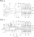
FIG. 3 is a top view of an internal-volume-ratio adjusting valve according to an embodiment, where the internal-volume-ratio adjusting valve is partially shown by a cross-section. -
FIG. 4 is a vertical front view of an internal-volume-ratio adjusting valve according to an embodiment. -
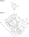
FIG. 5 is a front view of a valve body, showing an end surface of the valve body, as seen in the direction of arrow A inFIG. 4 . -
FIG. 6 is a perspective view of an internal-volume-ratio adjusting valve and a rotor casing according to an embodiment. -
FIG. 7 is a graph showing a case where the pressure of a just-before-discharge tooth space is optimum. -
FIG. 8 is a graph showing a case where the pressure of a just-before-discharge tooth space is in excessive compression. -
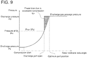
FIG. 9 is a graph showing a case where the pressure of a just-before-discharge tooth space is in insufficient compression. - Embodiments of the present invention will now be described in detail with reference to the accompanying drawings. It is intended, however, that unless particularly specified, dimensions, materials, shapes, relative positions and the like of components described in the embodiments shall be interpreted as illustrative only and not intended to limit the scope of the present invention.
- For instance, an expression of relative or absolute arrangement such as "in a direction", "along a direction", "parallel", "orthogonal", "centered", "concentric" and "coaxial" shall not be construed as indicating only the arrangement in a strict literal sense, but also includes a state where the arrangement is relatively displaced by a tolerance, or by an angle or a distance whereby it is possible to achieve the same function.
- For instance, an expression of an equal state such as "same" "equal" and "uniform" shall not be construed as indicating only the state in which the feature is strictly equal, but also includes a state in which there is a tolerance or a difference that can still achieve the same function.
- Further, for instance, an expression of a shape such as a rectangular shape or a cylindrical shape shall not be construed as only the geometrically strict shape, but also includes a shape with unevenness or chamfered corners within the range in which the same effect can be achieved.
- On the other hand, an expression such as "comprise", "include", "have", "contain" and "constitute" are not intended to be exclusive of other components.
- A screw compressor 10 (10A, 10B) according to some embodiments includes a
screw rotor 14 composed of a pair of male rotor and a female rotor and accommodated in arotor casing 12, as shown inFIGs. 1 and2 . Therotor casing 12 has asuction gas passage 15 and asuction port 16 through which a gas G is sucked, and adischarge port 18 and adischarge gas passage 19 through which the gas G after compression is discharged. Additionally, an internal-volume-ratio adjusting valve 20 capable of changing the internal volume ratio is provided. - Between the
screw rotor 14 and therotor casing 12, multiple tooth spaces St1, St2 are formed along the rotor axial direction. - The internal-volume-
ratio adjusting valve 20 includes avalve body 22 and acylinder 24 having acylinder rod 26 coupled to thevalve body 22. Thevalve body 22 is disposed within therotor casing 12, is movable along the rotor axial direction, and defines a discharge position at which the gas G is discharged through thedischarge port 18. Thecylinder 24 is disposed, for instance, so as to protrude to the outside of therotor casing 12. Thecylinder 24 contains at least one pressurizingchamber 28. Thecylinder rod 26 is disposed along the rotor axial direction and has a first end connected to thevalve body 22 and a second end introduced into the pressurizingchamber 28. Apiston 30 is disposed in the pressurizingchamber 28 and fixed to thecylinder rod 26. The pressurizingchamber 28 is divided into two pressurizing spaces s1 and s2 along the rotor axial direction by thepiston 30. - Further, a
first communication passage 32 communicating with the pressurizing space s2 of the two pressurizing spaces s1, s2 and with thedischarge gas passage 19 is provided. Asecond communication passage 34 connecting the pressurizing space s1 of the two pressurizing spaces s1, s2 with the tooth space St2 immediately adjacent to the tooth space St1 that communicates with thedischarge port 18 at the axial end of thescrew rotor 14 on the discharge side is provided. - In the above configuration, the gas G sucked through the
suction port 16 to the tooth space with the rotation of thescrew rotor 14 and sealed in the tooth space is compressed as the tooth space gradually contracts toward thedischarge port 18. The compressed gas is then discharged with a predetermined discharge pressure Pd from thedischarge port 18. - The gas G discharged from the
discharge port 18 and having the discharge pressure Pd is introduced into the pressurizing space s2 via thefirst communication passage 32. The gas G having an intermediate pressure Pm in the just-before-discharge tooth space St2 is introduced into the pressurizing space s1 via thesecond communication passage 34. - As shown in
FIGs. 3 and 4 , opposite forces f1 and f2 along the rotor axial direction are applied to thepiston 30, which divides the pressurizingchamber 28 into the two pressurizing spaces s1 and s2, due to the gas supplied to each of the pressurizing spaces s1 and s2. - As shown in
FIG. 7 , when the pressure Pm of the just-before-discharge tooth space St2 is equal to the discharge pressure Pd of the tooth space St1, the operating efficiency of thescrew compressor 10 is maximized. - In an operating example shown in
FIG. 8 , the pressure Pm of the just-before-discharge tooth space St2 is higher than the discharge pressure Pd, so that the operating efficiency is reduced due to power loss Lp. - In an operating example shown in
FIG. 9 , the pressure of the gas G in the just-before-discharge tooth space St2 is lower than the predetermined discharge pressure. In this case, the gas G will flow back from thedischarge port 18 into the tooth space during discharge, and the pressure of the tooth space increases to the discharge pressure Pd. Thus, extra work is caused for ejecting the backflow of the gas G from thedischarge port 18 to thedischarge gas passage 19, which reduces the compression efficiency. - In
FIGs. 1 and2 , thevalve body 22 of the internal-volume-ratio adjusting valve 20 moves in the rotor axial direction by the differential pressure between the pressures (forces) f1 and f2 applied to thepiston 30 from both sides. When the pressures (forces) f1 and f2 are equal to each other, i.e., when the discharge pressure Pd of the gas G discharged from thedischarge port 18 is equal to the pressure (intermediate pressure Pm) of the gas G in the just-before-discharge tooth space St2, the movement of thevalve body 22 in the axial direction is stopped. - In this way, since the
valve body 22 is automatically stopped at a rotor-axial-directional position where the discharge pressure Pd is equal to the intermediate pressure Pm, the discharge pressure Pd can be always made equal to the intermediate pressure Pm. Thus, it is possible to adjust the discharge position of thedischarge port 18 to be the optimum position automatically and continuously, and thus it is possible to constantly operate thescrew compressor 10 most efficiently. - On the other hand, since the
valve body 22 is operated by the difference between pressures applied to thepiston 30 from both sides, it is unnecessary to provide driving and control instruments for driving and controlling the internal-volume-ratio adjusting valve 20, and it is possible to reduce the cost. - In an embodiment, as shown in
FIGs. 1 and2 , the pressurizing space s2 communicating with thedischarge gas passage 19 via thefirst communication passage 32 is located on the suction port side with respect to thepiston 30. The pressurizing space s1 communicating with the just-before-discharge tooth space St2 is located on the discharge port side with respect to thepiston 30. Accordingly, the discharge pressure is transmitted to the pressurizing space s2, and the pressure of the just-before-discharge tooth space St2 is transmitted to the pressurizing space s1. - Thus, for instance, if the discharge pressure of the gas G is higher, the
valve body 22 of the internal-volume-ratio adjusting valve 20 is pushed toward the discharge port; whereas if the pressure of the just-before-discharge tooth space St2 is higher, thevalve body 22 of the internal-volume-ratio adjusting valve 20 is pushed toward the suction port. Consequently, the pressure of the gas G in the just-before-discharge tooth space St2 is automatically adjusted so as to be equal to the discharge pressure of the compressor. - In an embodiment, as shown in
FIGs. 3 to 5 , a part of the discharge port 18 (anotch 40 for defining the discharge position) is formed on asecond end surface 38 of thevalve body 22 facing thedischarge gas passage 19. - Additionally, as shown in
FIGs. 3 and 4 , therotor casing 12 has a suction-side end surface 42 and a discharge-side end surface 44. - When the tooth space St1 communicates with the
discharge port 18, the gas G sealed in the tooth space St1 is discharged to thedischarge port 18. - The dashed
dotted line 45 represents a rotational center axis of the male rotor or the female rotor of thescrew rotor 14. - In some embodiments, as shown in
FIGs. 1 and2 , thevalve body 22 has afirst end surface 36 facing thesuction gas space 21 communicating with thesuction gas passage 15 and a second end surface facing thedischarge gas passage 19. Thecylinder 24 has afirst pressurizing chamber 28 and asecond pressurizing chamber 46 arranged along the rotor axial direction. - The
cylinder rod 26 is introduced into the first pressurizingchamber 28 and thesecond pressurizing chamber 46. Apiston 30 is disposed in the first pressurizingchamber 28, and apiston 48 is disposed in thesecond pressurizing chamber 46. Thepistons cylinder rod 26. Thefirst pressurizing chamber 28 is divided into two pressurizing spaces s1 and s2 in the rotor axial direction by thepiston 30, and thesecond pressurizing chamber 46 is divided into two pressurizing spaces s3 and s4 in the rotor axial direction. - As shown in
FIGs. 3 and 4 , thepiston 48 receives a force f3 from the discharge side toward the suction side of thescrew rotor 14 by a gas supplied to the forward pressurizing space s3, and receives a force f4 from the suction side toward the discharge side of therotor casing 12 by a gas supplied to the backward pressurizing space s4. The forces f3 and f4 are applied to thepiston 48 in opposite directions to each other. - Further, as shown in
FIGs. 1 and2 , athird communication passage 50 connecting thesuction gas passage 15 with the forward pressurizing space s3 is provided, and afourth communication passage 52 connecting thedischarge gas passage 19 with the backward pressurizing space s4 is provided. Additionally, the compressor is configured so that the area of a pressure-receiving surface of thefirst end surface 36 receiving the pressure Ps of suction gas is equal to the area of a pressure-receiving surface p1 of thepiston 48 in the forward pressurizing space s3, and the area of a pressure-receiving surface of thesecond end surface 38 receiving the pressure Pd of discharge gas is equal to the area of a pressure-receiving surface p2 of thepiston 48 in the backward pressurizing space s4. The pressure-receiving surface p2 also includes anend surface 26a of thecylinder rod 26 so as to have the same area as the pressure-receiving surface of thedischarge gas passage 19. - In the above configuration, the gas G in the
suction gas passage 15 is introduced into the forward pressurizing space s3 via thethird communication passage 50, and the gas G from thedischarge gas passage 19 is introduced into the backward pressurizing space s4 via thefourth communication passage 52. - Let Asv1 be the area of the pressure-receiving surface of the
first end surface 36 of thevalve body 22, Asv2 be the area of the pressure-receiving surface of thesecond end surface 38, Ap1 be the area of the pressure-receiving surface p1 of thepiston 48, and Ap2 be the area of the pressure-receiving surface p2. Further, the areas of the pressure-receiving surfaces at which thepiston 30 receives the forces f1 and f2 from the pressurizing spaces s1 and s2 are assumed equal and defined as Ap3. - In this case, assuming that the direction from the discharge port toward the suction port is positive (forward), force F applied to the
valve body 22 is calculated by the following expression (1):
- In expression (1), since Asv1=Ap1 and Asv2=Ap2, expression (1) is rewritten as expression (2):

- Accordingly, when Pm is equal to Pd, F is 0, i.e., the
valve body 22 is stopped. That is, when thevalve body 22 is stopped, the operating efficiency of thescrew compressor 10 is maximized. - Thus, since the area of the pressure-receiving surface of the
first end surface 36 is equal to the area of the pressure-receiving surface p1 of thepiston 48 to which the force f3 is applied, the pressure of the gas G applied to thefirst end surface 36 and the force f3 are canceled. Further, since the area of the pressure-receiving surface of thesecond end surface 38 is equal to the area of the pressure-receiving surface p2 of thepiston 48 to which the force f4 is applied, the pressure of the gas G applied to thesecond end surface 38 and the force f4 are canceled. Consequently, only the forces f1 and f2 are applied to thevalve body 22, and thevalve body 22 is moved in the rotor axial direction by the difference between the forces f1 and f2. - According to the present embodiment, it is possible to automatically and continuously adjust the position of the
valve body 22 in the rotor axial direction into the optimum position so that the forces f1 and f2 are equal to each other by canceling the pressures of the gas G applied to thefirst end surface 36 and thesecond end surface 38 of thevalve body 22. Thus, it is possible to constantly operate thescrew compressor 10 most efficiently. - In the embodiments shown in
FIGs. 1 and2 , a part of thefirst communication passage 32 and a part of thefourth communication passage 52 are formed by a singlemain communication passage 31 communicating with thedischarge gas passage 19. - Additionally, a
partition wall 54 is disposed in thesingle cylinder 24 to form the first pressurizingchamber 28 and thesecond pressurizing chamber 46. Alternatively, two cylinders may be disposed, and the first pressurizingchamber 28 may be contained in one of the cylinders while thesecond pressurizing chamber 46 may be contained in the other of the cylinders. In this case, the two cylinders are arranged in series with asingle cylinder rod 26 so that thecylinder rod 26 is introduced into the two cylinder rods. - In an embodiment, as shown in
FIGs. 1 and4 , thesecond communication passage 34 includes ahollow portion 56 formed in thevalve body 22, a hollow portion 57 formed in thecylinder rod 26, afirst communication hole 58 formed in thevalve body 22 and connecting the just-before-discharge tooth space St2 and thehollow portion 56, and asecond communication hole 60 formed in thecylinder rod 26 and connecting the hollow portion 57 and the pressurizing space s1 of the first pressurizingchamber 28. - With the above configuration, since the
second communication passage 34 is formed within thevalve body 22 and thecylinder rod 26, a space outside thevalve body 22 and thecylinder rod 26 for forming thesecond communication passage 34 is unnecessary. Thus, it is possible to downsize the screw compressor 10 (10A, 10B). - In an embodiment, as shown in
FIGs. 2 and6 , thesecond communication passage 34 includes achannel 62 formed in therotor casing 12 facing a discharge side end of thescrew rotor 14. Thechannel 62 includes anopening 64 opening to the just-before-discharge tooth space St2. - With the above configuration, the just-before-discharge tooth space St2 communicates with the
second communication passage 34 at a position where the just-before-discharge tooth space St2 is closest to thedischarge port 18. Accordingly, it is possible to improve the precision for controlling the pressure of the gas G in the just-before-discharge tooth space St2 so as to be equal to the pressure of the discharge gas in thedischarge gas passage 19. -
FIG. 6 shows themale rotor 14a and thefemale rotor 14b inside therotor casing 12. In the embodiment shown inFIG. 6 , thechannel 62 is formed in therotor casing 12 facing a discharge-side end of themale rotor 14a, and theopening 64 opens to therotor casing 12 on the male rotor side. Additionally, thechannel 62 is connected to acommunication pipe 66 disposed outside therotor casing 12. Thecommunication pipe 66 communicates with the pressurizing space s1 via the communication hole 68 formed in the partition wall of thecylinder 24 and therotor casing 12, as shown inFIG. 2 . In an exemplary embodiment, thechannel 62 is formed in therotor casing 12 facing a discharge-side end of thefemale rotor 14b, and theopening 64 opens to therotor casing 12 on the female rotor side. - In an embodiment, as shown in
FIG. 1 , the first pressurizingchamber 28 is located on the discharge port side of thescrew rotor 14 with respect to thesecond pressurizing chamber 46, and the pressurizing space s1 communicating with thesecond communication passage 34, of the two pressurizing spaces s1 and s2 formed in the first pressurizingchamber 28, is located on the discharge port side of thescrew rotor 14 with respect to the pressurizing space s2. - With the above configuration, the pressurizing space s1 is located closest of the four pressurizing spaces s1 to s4 to the
discharge port 18. Thus, it is possible to reduce thehollow portions 56 and 57 formed inside thevalve body 22 and thecylinder rod 26, and it is possible to easily form the hollow portions. - According to some embodiments, it is possible to improve the efficiency of a screw compressor at low cost by equalizing the pressure of a gas in a tooth space just before discharge with the discharge pressure of the compressor, without expensive driving and control instruments.
-
- 10 (10A, 10B)
- Screw compressor
- 12
- Rotor casing
- 14
- Screw rotor
- 14a
- Male rotor
- 14b
- Female rotor
- 15
- Suction gas passage
- 16
- Suction port
- 18
- Discharge port
- 19
- Discharge gas passage
- 20
- Internal-volume-ratio adjusting valve
- 21
- Suction gas space
- 22
- Valve body
- 24
- Cylinder
- 26
- Cylinder rod
- 28
- First pressurizing chamber
- 30, 48
- Piston
- 31
- Main communication passage
- 32
- First communication passage
- 34
- Second communication passage
- 36
- First end surface
- 38
- Second end surface
- 40
- Notch
- 42
- Suction-side end surface
- 44
- Discharge-side end surface
- 46
- Second pressurizing chamber
- 50
- Third communication passage
- 52
- Fourth communication passage
- 54
- Partition wall
- 56, 57
- Hollow portion
- 58
- First communication hole
- 60
- Second communication hole
- 62
- Channel
- 64
- Opening
- 66
- Communication pipe
- 68
- Communication hole
- G
- Gas
- Pd
- Discharge pressure
- Pm
- Intermediate pressure
- Ps
- Suction pressure
- St1
- Tooth space
- St2
- Just-before-discharge tooth space
- p1, p2
- Pressure receiving surface
Claims (6)
- A screw compressor comprising:a screw rotor including a pair of a male rotor and a female rotor;a rotor casing accommodating the screw rotor, the rotor casing having a suction gas passage and a suction port through which a gas is sucked and a discharge port and a discharge gas passage through which the gas is discharged; andan internal-volume-ratio adjusting valve capable of changing an internal volume ratio,wherein the internal-volume-ratio adjusting valve includes:a valve body disposed inside the rotor casing, the valve body being movable along an axial direction of the screw rotor and defining a discharge position at which the gas is discharged from tooth spaces formed between the screw rotor and the rotor casing to the discharge port; anda cylinder containing at least one pressurizing chamber and having a cylinder rod and a piston, the cylinder rod being coupled to the valve body and being disposed along the axial direction of the screw rotor, the piston being fixed inside the or each pressurizing chamber to the cylinder rod and dividing the or each pressurizing chamber into two pressurizing spaces along the axial direction of the screw rotor,wherein the screw compressor further comprises:a first communication passage connecting a first one of the two pressurizing spaces with the discharge gas passage; anda second communication passage connecting a second one of the two pressurizing spaces with a just-before-discharge tooth space immediately before a tooth space that communicates with the discharge port.
- The screw compressor according to claim 1,
wherein the first one of the two pressurizing spaces is located on a suction port side with respect to the piston, and
wherein the second one of the two pressurizing spaces is located on a discharge port side with respect to the piston. - The screw compressor according to claim 1 or 2,
wherein the valve body has a first end surface facing a suction gas space communicating with the suction gas passage and a second end surface facing the discharge gas passage,
wherein the cylinder contains a first pressurizing chamber and a second pressurizing chamber which are arranged along the axial direction of the screw rotor,
wherein, in the first pressurizing chamber, the first one of the two pressurizing spaces separated by the piston communicates with the first communication passage, and the second one of the two pressurizing spaces communicates with the second communication passage,
wherein the screw compressor further comprises:a third communication passage connecting the suction gas passage with a forward pressurizing space of the two pressurizing spaces separated by the piston in the second pressurizing chamber, wherein, in the forward pressurizing space, the piston is pressurized in a forward direction from the discharge port toward the suction port; anda fourth communication passage connecting the discharge gas passage with a backward pressurizing space of the two pressurizing spaces formed in the second pressurizing chamber, wherein, in the backward pressurizing space, the piston is pressurized in a backward direction from the suction port toward the discharge port,wherein an area of a pressure-receiving surface of the first end surface pressurized by the gas in the suction gas space is equal to an area of a pressure-receiving surface of the piston in the forward pressurizing space, and an area of a pressure-receiving surface of the second end surface pressurized by the gas in the discharge gas passage is equal to an area of a pressure-receiving surface of the piston in the backward pressurizing space. - The screw compressor according to any one of claims 1 to 3,
wherein the second communication passage includes:a hollow portion formed in the valve body and in the cylinder rod;a first communication hole formed in the valve body and connecting the just-before-discharge tooth space and the hollow space; anda second communication hole formed in the cylinder rod and connecting the hollow portion and the second one of the two pressurizing spaces. - The screw compressor according to any one of claims 1 to 3,
wherein the second communication passage includes a channel formed in the rotor casing facing a discharge-side end of the screw rotor, and the channel has an opening open to the just-before-discharge tooth space from a wall surface of the rotor casing. - The screw compressor according to any one of claims 1 to 5,
wherein the cylinder contains a first pressurizing chamber and a second pressurizing chamber which are arranged along the axial direction of the screw rotor,
wherein the first pressurizing chamber is located on a discharge port side of the screw rotor with respect to the second pressurizing chamber, and
wherein, among the two pressurizing spaces formed in the first pressurizing chamber, the second one, communicating with the second communication passage, of the two pressurizing spaces is located on the discharge port side with respect to the first one of the two pressurizing spaces.
Applications Claiming Priority (2)
| Application Number | Priority Date | Filing Date | Title |
|---|---|---|---|
| JP2016231286 | 2016-11-29 | ||
| PCT/JP2017/037793 WO2018100911A1 (en) | 2016-11-29 | 2017-10-19 | Screw compressor |
Publications (2)
| Publication Number | Publication Date |
|---|---|
| EP3524818A1 true EP3524818A1 (en) | 2019-08-14 |
| EP3524818A4 EP3524818A4 (en) | 2019-11-20 |
Family
ID=62242445
Family Applications (1)
| Application Number | Title | Priority Date | Filing Date |
|---|---|---|---|
| EP17875093.1A Withdrawn EP3524818A4 (en) | 2016-11-29 | 2017-10-19 | Screw compressor |
Country Status (4)
| Country | Link |
|---|---|
| US (1) | US20200040896A1 (en) |
| EP (1) | EP3524818A4 (en) |
| JP (1) | JPWO2018100911A1 (en) |
| WO (1) | WO2018100911A1 (en) |
Cited By (1)
| Publication number | Priority date | Publication date | Assignee | Title |
|---|---|---|---|---|
| EP3786453A1 (en) * | 2019-09-02 | 2021-03-03 | Allan McDiarmid | Apparatus and method |
Families Citing this family (3)
| Publication number | Priority date | Publication date | Assignee | Title |
|---|---|---|---|---|
| WO2020178895A1 (en) * | 2019-03-01 | 2020-09-10 | 三菱電機株式会社 | Screw compressor |
| CN110779248B (en) * | 2019-10-12 | 2020-11-13 | 珠海格力电器股份有限公司 | Compressor control method, controller and air conditioning unit |
| CN114198311B (en) * | 2021-12-23 | 2024-10-25 | 珠海格力电器股份有限公司 | Fixed frequency screw compressor and refrigerating system |
Family Cites Families (8)
| Publication number | Priority date | Publication date | Assignee | Title |
|---|---|---|---|---|
| SE430709B (en) * | 1982-04-30 | 1983-12-05 | Sullair Tech Ab | SCREW COMPRESSOR WITH DEVICE FOR CONTROL OF INTERNAL COMPRESSION SCREW COMPRESSOR WITH DEVICE FOR REGULATION OF INTERNAL COMPRESSION |
| JP3778460B2 (en) | 1996-06-17 | 2006-05-24 | 株式会社前川製作所 | Slide valve for screw type fluid machine |
| JP5281978B2 (en) * | 2009-07-15 | 2013-09-04 | 日立アプライアンス株式会社 | Screw compressor |
| JP5355336B2 (en) * | 2009-10-05 | 2013-11-27 | 荏原冷熱システム株式会社 | Screw compressor and refrigerator |
| US8888466B2 (en) * | 2011-05-05 | 2014-11-18 | Johnson Controls Technology Company | Compressor |
| JP5818522B2 (en) * | 2011-06-13 | 2015-11-18 | 三菱電機株式会社 | Screw compressor |
| JP2013092091A (en) * | 2011-10-25 | 2013-05-16 | Mitsubishi Electric Corp | Double stage screw compressor |
| JP6136499B2 (en) | 2013-04-12 | 2017-05-31 | 三菱電機株式会社 | Screw compressor |
-
2017
- 2017-10-19 EP EP17875093.1A patent/EP3524818A4/en not_active Withdrawn
- 2017-10-19 US US16/339,449 patent/US20200040896A1/en not_active Abandoned
- 2017-10-19 WO PCT/JP2017/037793 patent/WO2018100911A1/en not_active Ceased
- 2017-10-19 JP JP2018553706A patent/JPWO2018100911A1/en active Pending
Cited By (1)
| Publication number | Priority date | Publication date | Assignee | Title |
|---|---|---|---|---|
| EP3786453A1 (en) * | 2019-09-02 | 2021-03-03 | Allan McDiarmid | Apparatus and method |
Also Published As
| Publication number | Publication date |
|---|---|
| US20200040896A1 (en) | 2020-02-06 |
| JPWO2018100911A1 (en) | 2019-10-17 |
| WO2018100911A1 (en) | 2018-06-07 |
| EP3524818A4 (en) | 2019-11-20 |
Similar Documents
| Publication | Publication Date | Title |
|---|---|---|
| US20200040896A1 (en) | Screw compressor | |
| KR101590281B1 (en) | Swash plate piston pump | |
| EP2177759A1 (en) | Tandem piston pump | |
| EP2988003B1 (en) | Piston of axial piston pump motor, cylinder block for axial piston pump motor, and axial piston pump motor | |
| US20060008375A1 (en) | Screw compressor | |
| GB2119446A (en) | Rotary positive-displacement gas-compressor | |
| EP1573203B1 (en) | Screw compressor with axially sliding capacity control valve | |
| US11674505B2 (en) | Swash-plate type piston pump | |
| TW202020594A (en) | Fluid pumps and related systems and methods | |
| JP5595209B2 (en) | Screw compressor | |
| JP5090883B2 (en) | 2 capacity pump | |
| CN105275804B (en) | The displacement-variable device and screw compressor of screw compressor | |
| EP3048301B1 (en) | Hydraulic radial piston device with improved pressure transition mechanism | |
| EP3660314B1 (en) | Screw compressor and refrigeration device | |
| JP5818522B2 (en) | Screw compressor | |
| JP2018091386A (en) | Electrically-driven fluid pressure type linear actuator | |
| JP2013228036A (en) | Fluid pressure actuator | |
| CN113090601B (en) | Remote pressure control valve and hydraulic system having the same | |
| JP6739646B2 (en) | Screw compressor | |
| JP5060444B2 (en) | Variable displacement vane pump | |
| JPH04342891A (en) | Screw compressor | |
| EP3557063A1 (en) | Screw compressor | |
| JP2005264791A (en) | Two-stage screw compressor and refrigeration system | |
| JP2016183602A (en) | Screw compressor | |
| JP6699456B2 (en) | Pump device |
Legal Events
| Date | Code | Title | Description |
|---|---|---|---|
| PUAI | Public reference made under article 153(3) epc to a published international application that has entered the european phase |
Free format text: ORIGINAL CODE: 0009012 |
|
| 17P | Request for examination filed |
Effective date: 20190507 |
|
| AK | Designated contracting states |
Kind code of ref document: A1 Designated state(s): AL AT BE BG CH CY CZ DE DK EE ES FI FR GB GR HR HU IE IS IT LI LT LU LV MC MK MT NL NO PL PT RO RS SE SI SK SM TR |
|
| AX | Request for extension of the european patent |
Extension state: BA ME |
|
| A4 | Supplementary search report drawn up and despatched |
Effective date: 20191021 |
|
| RIC1 | Information provided on ipc code assigned before grant |
Ipc: F04C 18/16 20060101AFI20191015BHEP Ipc: F04C 28/12 20060101ALI20191015BHEP Ipc: F04C 28/26 20060101ALI20191015BHEP |
|
| DAV | Request for validation of the european patent (deleted) | ||
| DAX | Request for extension of the european patent (deleted) | ||
| STAA | Information on the status of an ep patent application or granted ep patent |
Free format text: STATUS: THE APPLICATION HAS BEEN WITHDRAWN |
|
| 18W | Application withdrawn |
Effective date: 20200406 |