EP3524770B1 - System for blocking a tube, and stabiliser provided with such a system - Google Patents
System for blocking a tube, and stabiliser provided with such a system Download PDFInfo
- Publication number
- EP3524770B1 EP3524770B1 EP19153379.3A EP19153379A EP3524770B1 EP 3524770 B1 EP3524770 B1 EP 3524770B1 EP 19153379 A EP19153379 A EP 19153379A EP 3524770 B1 EP3524770 B1 EP 3524770B1
- Authority
- EP
- European Patent Office
- Prior art keywords
- tube
- blocking
- lever
- stabilizer
- previous
- Prior art date
- Legal status (The legal status is an assumption and is not a legal conclusion. Google has not performed a legal analysis and makes no representation as to the accuracy of the status listed.)
- Active
Links
- 239000003381 stabilizer Substances 0.000 title claims description 86
- 230000000903 blocking effect Effects 0.000 title claims description 42
- 230000009471 action Effects 0.000 claims description 10
- 230000000295 complement effect Effects 0.000 claims description 5
- 238000003825 pressing Methods 0.000 claims description 3
- 230000000994 depressogenic effect Effects 0.000 claims description 2
- 238000004519 manufacturing process Methods 0.000 description 5
- 238000005096 rolling process Methods 0.000 description 5
- 238000003780 insertion Methods 0.000 description 4
- 230000037431 insertion Effects 0.000 description 4
- 238000006073 displacement reaction Methods 0.000 description 3
- 230000000694 effects Effects 0.000 description 2
- 230000007246 mechanism Effects 0.000 description 2
- 230000006641 stabilisation Effects 0.000 description 2
- 238000011105 stabilization Methods 0.000 description 2
- 230000000087 stabilizing effect Effects 0.000 description 2
- 239000012815 thermoplastic material Substances 0.000 description 2
- 229910000838 Al alloy Inorganic materials 0.000 description 1
- 241001272720 Medialuna californiensis Species 0.000 description 1
- 230000003042 antagnostic effect Effects 0.000 description 1
- 230000000712 assembly Effects 0.000 description 1
- 238000000429 assembly Methods 0.000 description 1
- 238000005452 bending Methods 0.000 description 1
- 230000033228 biological regulation Effects 0.000 description 1
- 230000008859 change Effects 0.000 description 1
- 230000008878 coupling Effects 0.000 description 1
- 238000010168 coupling process Methods 0.000 description 1
- 238000005859 coupling reaction Methods 0.000 description 1
- 230000034994 death Effects 0.000 description 1
- 231100000517 death Toxicity 0.000 description 1
- 230000001066 destructive effect Effects 0.000 description 1
- 230000008034 disappearance Effects 0.000 description 1
- 229920001971 elastomer Polymers 0.000 description 1
- 239000000806 elastomer Substances 0.000 description 1
- 230000003100 immobilizing effect Effects 0.000 description 1
- 238000009434 installation Methods 0.000 description 1
- 238000007726 management method Methods 0.000 description 1
- 238000000034 method Methods 0.000 description 1
- 238000000465 moulding Methods 0.000 description 1
- 230000008569 process Effects 0.000 description 1
- 230000001681 protective effect Effects 0.000 description 1
- 230000002787 reinforcement Effects 0.000 description 1
- 230000003252 repetitive effect Effects 0.000 description 1
- 238000007665 sagging Methods 0.000 description 1
- 238000004904 shortening Methods 0.000 description 1
- 238000003860 storage Methods 0.000 description 1
- 238000012559 user support system Methods 0.000 description 1
Images


Classifications
-
- E—FIXED CONSTRUCTIONS
- E06—DOORS, WINDOWS, SHUTTERS, OR ROLLER BLINDS IN GENERAL; LADDERS
- E06C—LADDERS
- E06C7/00—Component parts, supporting parts, or accessories
- E06C7/42—Ladder feet; Supports therefor
- E06C7/423—Ladder stabilising struts
-
- E—FIXED CONSTRUCTIONS
- E06—DOORS, WINDOWS, SHUTTERS, OR ROLLER BLINDS IN GENERAL; LADDERS
- E06C—LADDERS
- E06C1/00—Ladders in general
- E06C1/02—Ladders in general with rigid longitudinal member or members
- E06C1/14—Ladders capable of standing by themselves
- E06C1/16—Ladders capable of standing by themselves with hinged struts which rest on the ground
- E06C1/20—Ladders capable of standing by themselves with hinged struts which rest on the ground with supporting struts formed as poles
- E06C1/22—Ladders capable of standing by themselves with hinged struts which rest on the ground with supporting struts formed as poles with extensible, e.g. telescopic, ladder parts or struts
-
- F—MECHANICAL ENGINEERING; LIGHTING; HEATING; WEAPONS; BLASTING
- F16—ENGINEERING ELEMENTS AND UNITS; GENERAL MEASURES FOR PRODUCING AND MAINTAINING EFFECTIVE FUNCTIONING OF MACHINES OR INSTALLATIONS; THERMAL INSULATION IN GENERAL
- F16B—DEVICES FOR FASTENING OR SECURING CONSTRUCTIONAL ELEMENTS OR MACHINE PARTS TOGETHER, e.g. NAILS, BOLTS, CIRCLIPS, CLAMPS, CLIPS OR WEDGES; JOINTS OR JOINTING
- F16B7/00—Connections of rods or tubes, e.g. of non-circular section, mutually, including resilient connections
- F16B7/10—Telescoping systems
- F16B7/14—Telescoping systems locking in intermediate non-discrete positions
- F16B7/1454—Telescoping systems locking in intermediate non-discrete positions with a clamp locking the telescoping members by swinging a handle provided with a locking cam
-
- E—FIXED CONSTRUCTIONS
- E04—BUILDING
- E04G—SCAFFOLDING; FORMS; SHUTTERING; BUILDING IMPLEMENTS OR AIDS, OR THEIR USE; HANDLING BUILDING MATERIALS ON THE SITE; REPAIRING, BREAKING-UP OR OTHER WORK ON EXISTING BUILDINGS
- E04G25/00—Shores or struts; Chocks
- E04G25/04—Shores or struts; Chocks telescopic
- E04G2025/045—Shores or struts; Chocks telescopic which telescoping action effected by a lever
-
- F—MECHANICAL ENGINEERING; LIGHTING; HEATING; WEAPONS; BLASTING
- F16—ENGINEERING ELEMENTS AND UNITS; GENERAL MEASURES FOR PRODUCING AND MAINTAINING EFFECTIVE FUNCTIONING OF MACHINES OR INSTALLATIONS; THERMAL INSULATION IN GENERAL
- F16B—DEVICES FOR FASTENING OR SECURING CONSTRUCTIONAL ELEMENTS OR MACHINE PARTS TOGETHER, e.g. NAILS, BOLTS, CIRCLIPS, CLAMPS, CLIPS OR WEDGES; JOINTS OR JOINTING
- F16B2/00—Friction-grip releasable fastenings
- F16B2/20—Clips, i.e. with gripping action effected solely by the inherent resistance to deformation of the material of the fastening
- F16B2/22—Clips, i.e. with gripping action effected solely by the inherent resistance to deformation of the material of the fastening of resilient material, e.g. rubbery material
- F16B2/24—Clips, i.e. with gripping action effected solely by the inherent resistance to deformation of the material of the fastening of resilient material, e.g. rubbery material of metal
- F16B2/241—Clips, i.e. with gripping action effected solely by the inherent resistance to deformation of the material of the fastening of resilient material, e.g. rubbery material of metal of sheet metal
- F16B2/245—Clips, i.e. with gripping action effected solely by the inherent resistance to deformation of the material of the fastening of resilient material, e.g. rubbery material of metal of sheet metal external, i.e. with contracting action
- F16B2/246—Clips, i.e. with gripping action effected solely by the inherent resistance to deformation of the material of the fastening of resilient material, e.g. rubbery material of metal of sheet metal external, i.e. with contracting action the clip being released by tilting the clip or a part thereof to a position in which the axis of the openings surrounding the gripped elements is parallel to, or coincides with, the axis of the gripped elements
Definitions
- the invention relates to the field of stabilization devices intended to be mounted on work equipment at height.
- the invention relates to a system for locking stabilizers fitted to a device for working at height.
- stepladders according to standard NF EN 14183
- portable ladders according to standard NF EN 131 EN
- rolling scaffolding within the meaning of standards NF EN 1004 and NF P 93 -520
- rolling platforms within the meaning of standards NF 93-353 and NF 93-352.
- Equipment for working at height meets strict safety standards, in order to ensure the safety of users, and in particular in order to limit the risk of falls.
- Such falls may result from a overturning of the working at height device, in particular for rolling platforms or ladders.
- Such stabilizers are generally in the form of telescopic tubes, offering height adjustment.
- the stabilizers thus equipped with such tubes can rest on the ground surrounding the working device at height, whatever the difference in level, within the limit of the length of the tubes.
- the stabilizers provide stability to the device for working at height, in particular by limiting the risk of lateral rollover when used by a user.
- Stabilizers generally have an end hinged to a piece of equipment for working at height, so as to facilitate their transport and deployment.
- the stabilizer When moving the work equipment, the stabilizer is generally retracted, then hooked directly to the work at height device, by means of devices provided for this purpose.
- Stabilizers can be distinguished into different categories, depending on the height adjustment mode they offer.
- the height adjustment is carried out by predetermined positions, as disclosed for example in the document US 3901354 , which proposes a system comprising a pin which is positioned within notches arranged in one of the tubes.
- Similar blocking modes are also presented in the documents US 1610596 , US 3508628 , US 4175641 , US 4433754 , US 4947962 , US 2008000721 .
- Such locking modes do not allow precise adjustment of the height of a stabilizer, due to the too great spacing between the predetermined positions. A user can thus find himself in a situation where stable support is impossible, forcing him to move the working device at height, in order to be able to find a support surface for the stabilizers.
- the height adjustment is obtained by a so-called millimeter adjustment, that is to say over a predetermined adjustment range.
- Such an adjustment is obtained by providing the stabilizer with a means making it possible to lock and unlock the telescopic tubes between them.
- the user unlocks the tubes between them, adjusts the length to the desired dimension, by moving one of the tubes, then locks the tubes together.
- clamping ring assemblies have been described, for example in documents US 4872529 , GB 2180875 , or WO 2012168684 .
- ring arrangements do not offer optimum security, since there is nothing to indicate to the user that the tightening torque is sufficient to allow secure locking of the tubes between them.
- a ring in particular when made of a thermoplastic material, can deteriorate from repetitive tightening and loosening.
- the installation of a stabilizer equipped with a ring is not without difficulties. The user must first loosen the ring, position the stabilizer by positioning the tubes to each other, then tighten the ring, while maintaining the position of the stabilizer.
- Such an assembly requires the use of both hands on the stabilizer, and a certain dexterity on the part of the user, to maintain the position when the ring is tightened.
- the document FR 1169142 proposes a support support comprising two tubes mounted to slide relative to each other.
- a first tube is provided with a sleeve comprising a conical recess, in order to allow the displacement of a locking plate.
- a second tube passes through the plate, through an opening.
- the plate is curved and has at its end a part forming a handle. When no force is applied to the handle, the spring pushes the plate down, locking the tubes together, the plate being released by pressing on the lower part of the handle.
- the mechanism described in the document FR 1169142 has various drawbacks.
- the handle is located in a location preventing easy gripping. The user is obliged to position both hands to manipulate the stabilizer.
- the position of the spring makes the adjustment imprecise, the plate making the bracing not being guided, so that the user must press on the part. lower part of the handle to allow movement of the plate. The user must therefore position his hand at a very precise location, on the handle, making the sleeve inconvenient to use.
- the document FR 2946989 discloses a stabilizing leg provided with a locking member for lengthening or shortening the leg.
- the stabilization device is actuated by biasing an L-shaped handle, allowing the release of a shoring slide.
- the handling of such a system entails risks of jamming, the spring being disposed in the vicinity of the gripping surface, that is to say near the place where the user positions his fingers to apply the handle.
- the handle is arranged in a not very intuitive direction, requiring the user to turn his hand, which is not very ergonomic.
- the document EP2213885 describes a support device comprising at least one support foot for a camera or cameras, formed of an outer tube and an inner tube connected together telescopically and provided with a clamping device comprising a sleeve which is fixed at one end of the outer tube.
- This document shows a locking system according to the preamble of claim 1.
- the invention proposes to respond to the aforementioned drawbacks.
- a first object of the invention is to provide a locking system for telescopic stabilizer tubes, for work equipment at height, the locking system allowing deployment of the stabilizer with one hand.
- a second object of the invention is to provide such a system, ergonomic and without risk for the user, in particular in terms of finger jamming.
- a third object of the invention is to provide such a system, easy to assemble and having reduced production costs.
- a fourth object of the invention is to provide a stabilizer provided with such a system.
- a fifth object of the invention is to provide equipment for working at height comprising such a stabilizer.
- FIG. 1 shows a device 1 for working at height, provided for example with two telescopic stabilizers 2, each comprising a locking system 3.
- the stabilizers 2 have in particular a stabilizing function, by forming supports which reduce the risk of the working device 1 tipping sideways when a user climbs on it.
- the device 1 for working at height is a ladder 1, comprising two parallel uprights 4 connected by cross members 5.
- the device 1 for working at height is a step, a stepladder, an individual rolling platform, a light individual rolling platform, or a scaffolding.
- the stabilizers 2 of scale 1 are symmetrical to one another. Consequently, we limit our to the description of a single stabilizer 2, the other stabilizer 2 being structurally identical except for a symmetry, with respect to a plane perpendicular to the sleepers 5, the plane intersecting the middle of the sleepers 5.
- the stabilizer 2 comprises a first tube 6, mounted to slide in a second tube 7, so as to form a telescopic assembly 8.
- the tubes 6, 7 are advantageously metallic, for example made of aluminum alloy, which gives them a reduced mass, and facilitates their handling by the user.
- the first tube 6 is a hollow cylinder, advantageously profiled, which facilitates manufacture.
- the second tube 7 comprises an internal hollow cylinder 9 , receiving the first tube 6 in sliding manner.
- the internal hollow cylinder 9 is connected by means of ribs 10 to an external hollow cylinder 11.
- Such an arrangement makes it possible to reinforce the rigidity of the second tube 7, preventing sagging of the second tube 7 when the user climbs the ladder 1.
- the first tube 6 comprises a first end 12 articulated to the upright 4, so as to allow the movement of the stabilizer 2, as well as a second end (not visible in the figures) inserted within the second tube 7.
- the second tube 7 has a first end part 13 , intended to come into contact with the ground, and a second end part 14 , allowing the locking system 3 to stop, as described below.
- the first end part 13 is covered with a protective cap 15 , made for example of thermoplastic material.
- the locking system 3 makes it possible to block the translation of the first tube 6 with respect to the second tube 7.
- the translation of the first tube 6 relative to the second tube 7 can be released, in the direction of deployment of the stabilizer 2, by exerting a tensile force on the first tube 7, that is to say. say a force having an intensity greater than a predefined value, aimed at moving the first tube 6 away from the second tube 7.
- a tensile force on the first tube 7, that is to say. say a force having an intensity greater than a predefined value, aimed at moving the first tube 6 away from the second tube 7.
- the translation of the first tube 6 relative to the second tube 7 is released in the direction of deployment and in the direction of retraction of the stabilizer 2, by means of an action on a button 16 integrated within the locking system 3 , the button 16 being made accessible to the user.
- the actuation of the button 16 is a means for adjusting the length of the telescopic assembly 8 , making it possible, depending on the desired position, to retract or deploy the stabilizer 2.
- a pulling action on the second tube 7 is a means for adjusting the deployment. stabilizer 2.
- Such arrangements make it possible to adapt the length of stabilizer 2 to any ground configuration, within the limit of the maximum extension length of stabilizer 2.
- Stabilizer 2 offers continuous adjustment, referred to as millimeter.
- the stabilizer 2 comprises a link 17, which acts in particular as a reinforcement at the level of the second tube 7, by taking up the bending stresses, which stiffens the stabilizer 2, making use of the scale 1 safer.
- the rod 17 comprises a first end 18, pivoting relative to the upright 4, and a second end 19 , pivoting relative to the second tube 7, so as to give the second tube 7 a circular translational movement.
- Such an arrangement has the particular function of guiding the pivoting movement of the telescopic assembly 8 relative to the upright 4.
- the stabilizer 2 thus takes on the constitution of an articulated system, helping to make it manipulable with one hand.
- the stabilizer 2 is in the stowed position, the telescopic assembly 8 being retracted.
- the connecting rod 17 and the telescopic assembly 8 are hooked parallel to the upright, for example by means of a device 20 for hooking by clipping.
- the locking system 3 is then in a locked state, immobilizing the telescopic assembly 8 , and by extension the stabilizer 2.
- the stabilizer 2 is therefore kept immobile by both the locking system 3 and the hooking device 20. .
- Such redundancy prevents untimely unhooking of the stabilizer 2 from its storage position, including when the coupling device 20 is faulty.
- a tensile force is exerted on the second tube 7, against the attachment device 20.
- the user positions one hand on the locking system 3 , and his other hand on the upright 4, which makes it possible to take support in order to release the stabilizer 2 from the upright 4.
- the stabilizer 2 is shown being deployed in an intermediate position.
- the user continues the tensile force making it possible to tilt the second tube 7.
- the rod 17 in the deployment of the stabilizer 2 guides the movement. stabilizer 2 descent.
- the stabilizer can then be operated with one hand, the other hand holding scale 1 for example to prevent it from moving.
- the stabilizer 2 is in a deployed position, making it possible to support the device 1 for working at height, the first end part 13 being in contact with the ground.
- the user releases the stabilizer 2, the desired position being obtained.
- the user supports the ladder 1, which is thus made stable, limiting the risk of lateral overturning.
- the terms “longitudinal” or “longitudinally” refer to a direction coincident with the X axis
- the terms “transverse” or “transversely” refer to a direction coincident with the Y axis
- the terms “vertical” or “vertically” refer to a direction coincident with the Z axis.
- the terms of absolute position such as “front”, “rear”, “top” , “bottom”, “left”, “right”, or relative like “above”, “upper”, “below”, “lower”, “outside”, “inside” are defined with respect to the second tube 7.
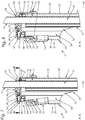
- the locking system 3 comprises a support means, for example a box 21, a lever 22, as well as a return means such as an elastic stud 23.
- the housing 21 is made integral with the second tube 7, and comprises a boss 24 serving in particular as a support to allow the rotation of the lever 22.
- the lever 22 is in the form of a plate, provided with an actuating part 25 , and a locking part 26.
- the actuation part 25 is provided with the button 16, the locking part 26 comprises an opening 27, having a contour 28, homothetically greater than the section of the first tube 6.
- the first tube 6 moves within the opening 27, a functional play of the order for example of a few millimeters, being left between the first tube 6 and the opening 27.
- a play makes it possible to move the part. 26 for locking with respect to the first tube 6.
- the locking part 26 is able to be positioned in an overhanging position on the first tube 6.
- the lever 22 is arranged so that the actuating part 25 and the locking part 26 are both arranged on either side of the boss 24.
- the lever 22 pivots around the boss 24, which causes an upward movement of the locking part 26.
- Pressure on the actuating part 25 makes it possible to give an orientation to the lever 22, and thus to change the angle between the locking part 26 and the direction of extension of the first tube 6.
- the weight of the scale 1 with under the user located above has the consequence of creating a mechanical action by the first tube 6 on the contour 28 .
- Due to the blocking of the contour 28 on the first tube 6, a such mechanical action drives the blocking part 26 downwards, increasing the angle between the blocking part 26 , and the direction of extension of the first tube 6, which further reinforces the blocking effect linked to the arcing phenomenon -butting.
- increasing the load increases the blocking force.
- Such an effect is advantageous in terms of safety of use for the user.
- the contour 28 is not in contact with the first tube 6, which allows the passage of the first tube 6 and makes it possible to obtain the extension or the retraction of the telescopic assembly 8 , allowing any movement of the stabilizer 2.
- the block 23 aims to maintain the locking part 26 in a situation of equilibrium, that is to say when the user does not exert any pressure on the button 16.
- a pressure or a push exerted on the button 16 causes a biasing of the lever 22, against the stud 23. Following such a mechanical action, the lever 22 pivots and crushes the stud 23, while positioning the locking part 26. in the unlocked position.
- the release of the button 16 causes the disappearance of the force antagonistic to the stud 23.
- the stud 23 returns to its initial shape, that is to say before crushing, by causing the return of the lever 22 to a position of equilibrium which corresponds. to a locked position.
- Such an operation is advantageous, because it offers a means making it possible to unlock and block the telescopic assembly 8 , respectively by a pressure action, or a simple release of the button 16.
- the locking system 3 In the state of equilibrium, that is to say. ie when the button 16 is not requested, the locking system 3 is in the locked position.
- the stabilizer 2 is therefore by default in the locked position, which prevents any user error, and increases the safety of use of the scale 1.
- the case 21 is advantageously hollow.
- the housing 21 comprises an outer wall 29 defining a substantially oblong shape in a transverse plane.
- the case advantageously has two recesses 30 allowing for example the fingers to grip the locking system 3 , which makes it easier to maintain the support of the handle using one hand.
- the housing 21 extends substantially in a vertical direction between an upper part 31 and a lower part 32.
- a lateral part 33 connects the upper part 31 to the lower part 32.
- the upper part 31 is positioned in the vicinity of the second end part 14 , while the lower part 32 is arranged above the articulation of the connecting rod 17. In this way, the risk of jamming the fingers when handling the stabilizer 2 is limited.
- the upper part 31 advantageously comprises a substantially planar portion, and a bore 34 allowing the first tube 6 to pass through.
- the lower part 32 of the housing 21 has a rim 35 provided projecting from the outer wall 29 and a cavity 36, having for example the function of forming an obstacle for the hand of a user handling the locking system 3.
- the cavity 36 advantageously comprises a fixing portion 37 , making it possible to receive the second tube 7, and an actuating portion 38 allowing in particular the reception of the actuating part 25 of the lever 22.
- the fixing portion 37 has an inner wall 39 defining a fraction 40 of cylindrical shape, complementary to the second tube 7, allowing the second tube 7 to be fitted by fitting into the fixing portion 37 , the holding in position being carried out at the same time. 'Using a fixing screw 55.
- the fraction 40 of cylindrical shape is advantageously provided with ridges 41, limiting the contact surfaces between the inner wall 39 and the second tube 7, which facilitates assembly.
- the upper part 31 of the fixing portion 37 comprises a top zone 42 and the bore 34.
- the bore 34 is advantageously cylindrical and has a sufficiently large diameter to allow movement of the first tube 6 without contact with the bore 34, while avoiding the risk of introducing a finger when handling the stabilizer 2, or other foreign bodies.
- the upper part 31 comprises, for example within the fixing portion 37 , a housing 43 adapted to the insertion of the deformable elastic stud 23 , facilitating assembly.
- Unit 43 is advantageously produced by molding within the inner wall 39 of the housing 21, on the upper part 31. In this way, the stud 23 protrudes from the housing 43 while being oriented downwards, which makes it possible to come into contact with the lever 22.
- the stud 23 is arranged between the lever 22 and the upper part 31 , so as to exert a thrust force, when biased and deformed by the lever 22.
- the actuation portion 38 comprises in particular the actuation part 25 , the stud 23 and the boss 24.
- the part 26 for locking the lever 22 is included within the fixing portion 37.
- the box 21 thus surrounds the lever 22, the stud 23 and the boss 24, which makes it possible to create a physical protection of the actuating mechanism of the locking system 3. In this way, any risk of pinching or for example of involuntary introduction of a finger is avoided.
- the actuating portion 38 is provided with a recess 44 starting from the upper part 31 and extending to a predefined position of the lateral part 33. Such a position corresponds to the position reached by the button 16 during the rotation of the lever 22 around the boss 24 .
- the recess 44 opens onto the upper part 31 of the housing 21, which in particular allows the introduction of the lever 22. The assembly of the locking system 3 is thus facilitated.
- the recess 44 advantageously has dimensions complementary to the dimension of the lever 22, so that a minimum clearance is left between the recess and the lever 22. In this way, optimal guidance is provided to the lever by the lever. recess 44, making it possible to obtain a movement of the lever 22 which is substantially identical regardless of the location of the user's effort on the button 16.
- the boss 24 protrudes from the inner wall 39 of the housing 21 and extends both in a vertical and transverse direction.
- the boss 24 has sufficient dimensions to enable the load exerted by the lever 22 to be supported.
- the boss 24 comprises a plate 46 and at least one support section 47.
- the plate 46 which extends along the width of the recess 44, acts as a support for the support section 47 , making it possible to limit any phenomenon of stress concentration around the boss 24.
- the boss 24 is provided with at least one support section 47 , for example two.
- the support sections 47 are preferably both arranged against the inner wall 39 , as can be seen in the figure. figure 10 . In this way, the mechanical actions exerted by the lever 22 are taken up directly by the inner wall 39.
- the support section 47 advantageously has, along a vertical plane, the shape of a half-moon.
- the support section 47 comprises a vertical surface 48 , a curved surface 49.
- the curved surface 49 allows the lever 22 to be pivoted.
- the lever 22 has, for example, an elbow 50, between the actuating part 25 and the locking part 26.
- the actuating part 25 comprises an end portion 51 , allowing the insertion of the button 16.
- the button 16 is arranged so as to protrude from the outer wall 29 of the housing 21 in equilibrium, that is to say when the blocking system 3 is in a blocked state. The button 16 is thus physically and visually accessible to the user, facilitating the handling of the stabilizer 2.
- the button 16 comprises an incision 52, having a shape complementary to the actuation part 25. In this way, the button 16 is engaged within the lever 22.
- the maintaining in position of the button 16 is advantageously accomplished by means of an elastic tongue 53 , projecting within a crevice formed on the part 25 d. 'actuation.
- the box 21 comprises a cover 54, clipped using two notches 45 made on the upper part 31 , within the recess 44.
- access to the lever 22 is physically impossible, which helps prevent any risk involuntary introduction of the user's fingers, and avoids the insertion of foreign body or any other obstacle hindering the operation of the locking system 3.
- the housing 21, and therefore the boss 24, are for example obtained by foundry processes.
Description
L'invention a trait au domaine des dispositifs de stabilisation destinés à être montés sur des équipements de travail en hauteur.The invention relates to the field of stabilization devices intended to be mounted on work equipment at height.
Plus particulièrement, l'invention se rapporte à un système de blocage de stabilisateurs équipant un dispositif de travail en hauteur.More particularly, the invention relates to a system for locking stabilizers fitted to a device for working at height.
Par "dispositifs de travail en hauteur", il est fait référence en particulier à des escabeaux selon la norme NF EN 14183, des échelles portables selon la norme NF EN 131 EN, des échafaudages roulants au sens des normes NF EN 1004 et NF P 93-520, ainsi que des plateformes roulantes au sens des normes NF 93-353 et NF 93-352.By "devices for working at height", reference is made in particular to stepladders according to standard NF EN 14183, portable ladders according to standard NF EN 131 EN, rolling scaffolding within the meaning of standards NF EN 1004 and NF P 93 -520, as well as rolling platforms within the meaning of standards NF 93-353 and NF 93-352.
Les équipements de travail en hauteur répondent à des normes de sécurité strictes, afin d'assurer la sécurité des utilisateurs, et en particulier afin de limiter les risques de chute.Equipment for working at height meets strict safety standards, in order to ensure the safety of users, and in particular in order to limit the risk of falls.
Les chutes de hauteur ont été en 2016 à l'origine de 16% des incapacités permanentes et à l'origine de 16% des décès liés à des accidents du travail en France, tous domaines confondus (voir Rapport de gestion 2016 de l'Assurance maladie Risques professionnels, partie 5 - Sinistralité tous CTN, tableau 2, P.12).Falls from heights in 2016 were the cause of 16% of permanent disabilities and the cause of 16% of deaths related to work-related accidents in France, all areas combined (see Insurance Management Report 2016 illness Occupational risks, part 5 - Claims for all CTNs, table 2, P.12).
De telles chutes peuvent provenir d'un renversement du dispositif de travail en hauteur, en particulier pour les plateformes roulantes ou les échelles.Such falls may result from a overturning of the working at height device, in particular for rolling platforms or ladders.
Afin d'éviter la survenue d'un pareil accident, la réglementation applicable relative au travail en hauteur, notamment les articles R. 4323-81 à R. 4323-88 du code du travail, soumet les dispositifs de travail en hauteur à un certain nombre de prescriptions, et notamment le fait d'être stable en utilisation.In order to avoid the occurrence of such an accident, the applicable regulations relating to work at height, in particular Articles R. 4323-81 to R. 4323-88 of the Labor Code, subject working at height devices to a certain number of prescriptions, and in particular being stable in use.
Pour parvenir à un tel résultat, il est connu de munir le dispositif de travail en hauteur de stabilisateurs.To achieve such a result, it is known to provide the device for working at height with stabilizers.
De tels stabilisateurs se présentent généralement sous la forme de tubes télescopiques, offrant un réglage en hauteur.Such stabilizers are generally in the form of telescopic tubes, offering height adjustment.
Les stabilisateurs ainsi équipés de tels tubes peuvent prendre appui sur le sol environnant le dispositif de travail en hauteur, quelle que soit la dénivellation, dans la limite de la longueur des tubes.The stabilizers thus equipped with such tubes can rest on the ground surrounding the working device at height, whatever the difference in level, within the limit of the length of the tubes.
De cette façon, les stabilisateurs confèrent une stabilité au dispositif de travail en hauteur, notamment en limitant le risque de renversement latéral lorsqu'un utilisateur en fait usage.In this way, the stabilizers provide stability to the device for working at height, in particular by limiting the risk of lateral rollover when used by a user.
Les stabilisateurs présentent en général une extrémité articulée à un élément de l'équipement de travail en hauteur, de manière à faciliter leur transport et leur déploiement.Stabilizers generally have an end hinged to a piece of equipment for working at height, so as to facilitate their transport and deployment.
Lors du déplacement de l'équipement de travail, le stabilisateur est généralement rétracté, puis accroché directement au dispositif de travail en hauteur, par l'intermédiaire de dispositifs prévus à cet effet.When moving the work equipment, the stabilizer is generally retracted, then hooked directly to the work at height device, by means of devices provided for this purpose.
Les stabilisateurs peuvent être distingués en différentes catégories, selon le mode de réglage en hauteur qu'ils offrent.Stabilizers can be distinguished into different categories, depending on the height adjustment mode they offer.
Pour une première catégorie de stabilisateurs, le réglage en hauteur s'effectue par positions prédéterminées, comme divulgué par exemple dans le document
Dans une deuxième catégorie de stabilisateurs, le réglage en hauteur est obtenu par un réglage dit millimétrique, c'est-à-dire sur une plage de réglage prédéterminée. Un tel réglage est obtenu en munissant le stabilisateur d'un moyen permettant de verrouiller et déverrouiller entre eux les tubes télescopiques. Pour régler la hauteur du stabilisateur, l'utilisateur déverrouille les tubes entre eux, ajuste la longueur à la dimension souhaitée, en déplaçant un des tubes, puis verrouille les tubes entre eux.In a second category of stabilizers, the height adjustment is obtained by a so-called millimeter adjustment, that is to say over a predetermined adjustment range. Such an adjustment is obtained by providing the stabilizer with a means making it possible to lock and unlock the telescopic tubes between them. To adjust the height of the stabilizer, the user unlocks the tubes between them, adjusts the length to the desired dimension, by moving one of the tubes, then locks the tubes together.
Pour réaliser un tel réglage millimétrique, des montages à bague de serrage ont été décrits, par exemple dans les documents
Il est également connu de munir une paroi d'un tube d'un stabilisateur d'une vis, apte à venir serrer le tube par adhérence. Un tel principe est par exemple divulgué dans le document
Afin de pallier les inconvénients des systèmes présentés ci-dessus, il a été proposé d'utiliser un arc-boutement pour bloquer entre eux les tubes d'un stabilisateur.In order to overcome the drawbacks of the systems presented above, it has been proposed to use an overhang to block the tubes of a stabilizer between them.
Ainsi, le document
Le mécanisme décrit dans le document
Le document
L'invention se propose de répondre aux inconvénients précités.The invention proposes to respond to the aforementioned drawbacks.
Un premier objet de l'invention est de proposer un système de blocage de tubes télescopiques de stabilisateur, pour un équipement de travail en hauteur, le système de blocage permettant un déploiement du stabilisateur d'une seule main.A first object of the invention is to provide a locking system for telescopic stabilizer tubes, for work equipment at height, the locking system allowing deployment of the stabilizer with one hand.
Un deuxième objet de l'invention est de proposer un tel système, ergonomique et sans risque pour l'utilisateur, notamment en terme de coincement de doigts.A second object of the invention is to provide such a system, ergonomic and without risk for the user, in particular in terms of finger jamming.
Un troisième objet de l'invention est de proposer un tel système, facile à monter et présentant des coûts d'obtention réduits.A third object of the invention is to provide such a system, easy to assemble and having reduced production costs.
Un quatrième objet de l'invention est de proposer un stabilisateur muni d'un tel système.A fourth object of the invention is to provide a stabilizer provided with such a system.
Un cinquième objet de l'invention est de proposer un équipement pour le travail en hauteur comprenant un tel stabilisateur.A fifth object of the invention is to provide equipment for working at height comprising such a stabilizer.
A cet effet, il est proposé, en premier lieu, un système de blocage du coulissement d'un premier tube par rapport à un deuxième tube d'un stabilisateur d'un dispositif de travail en hauteur, le système de blocage comprenant :
- un moyen de support, destiné à être solidaire du deuxième tube, le moyen de support comprenant un bossage ;
- un levier comprenant une partie d'actionnement, et une partie de blocage, disposées de part et d'autre du bossage, la partie de blocage comprenant une ouverture destinée au déplacement du premier tube, le levier pivotant autour du bossage entre une position de déblocage, apte à permettre le déplacement du premier tube, et une position de blocage, apte à permettre le positionnement du premier tube en arc-boutement sur l'ouverture ;
- un moyen de rappel, disposé entre le moyen de support et la partie de blocage, exerçant un effort de rappel sur la partie de blocage maintenant le levier en position de blocage, le moyen de rappel exerçant un effort de poussée sur la partie de blocage, de sorte qu'une action de pression appliquée sur la partie d'actionnement fasse pivoter le levier entraînant le positionnement du moyen de blocage en position de déblocage,
- a support means, intended to be integral with the second tube, the support means comprising a boss;
- a lever comprising an actuating part, and a locking part, arranged on either side of the boss, the locking part comprising an opening intended for the movement of the first tube, the lever pivoting around the boss between an unlocking position , adapted to allow the displacement of the first tube, and a blocking position, adapted to allow the positioning of the first tube in bracing on the opening;
- a return means, arranged between the support means and the blocking part, exerting a return force on the blocking part maintaining the lever in the blocking position, the return means exerting a pushing force on the blocking part, so that a pressure action applied to the actuating part rotates the lever causing the positioning of the locking means in the unlocked position,
Diverses caractéristiques supplémentaires peuvent être prévues, seules ou en combinaison :
- le moyen de support comprend un boitier entourant la partie de blocage et le moyen de rappel ;
- le boitier comprend un évidement présentant des dimensions complémentaires à la partie d'actionnement ;
- le boitier comprend un alésage destiné au passage du premier tube et une fraction de forme cylindrique de dimension supérieure à l'alésage, la fraction de forme cylindrique étant destinée à être emmanchée sur le deuxième tube ;
- le bossage est pourvu une section d'appui comprenant une surface incurvée, en contact avec le levier, la section d'appui étant configurée pour permettre la rotation du levier ;
- le moyen de rappel comprend un plot élastique déformable ;
- il comprend un bouton, monté enfoncé et maintenu enclipsé sur une portion extrême de la partie d'actionnement
- the support means comprises a housing surrounding the blocking part and the return means;
- the housing comprises a recess having dimensions complementary to the actuating part;
- the housing comprises a bore intended for the passage of the first tube and a portion of cylindrical shape of dimension greater than the bore, the portion of cylindrical shape being intended to be fitted onto the second tube;
- the boss is provided with a bearing section comprising a curved surface, in contact with the lever, the bearing section being configured to allow rotation of the lever;
- the return means comprises a deformable elastic pad;
- it comprises a button, mounted depressed and kept clipped on an end portion of the actuating part
Il est proposé, en deuxième lieu, un stabilisateur télescopique d'un dispositif de travail en hauteur, le stabilisateur comprenant :
- un premier tube,
- un deuxième tube,
- un système de blocage tel que présenté ci-dessus, le système de blocage étant solidaire par rapport au deuxième tube, le premier tube traversant l'ouverture.
- a first hit,
- a second tube,
- a locking system as presented above, the locking system being integral with the second tube, the first tube passing through the opening.
Il est proposé, en troisième lieu, un dispositif de travail en hauteur intégrant un stabilisateur tel que présenté ci-dessus.Thirdly, there is proposed a device for working at height incorporating a stabilizer as presented above.
D'autres caractéristiques et avantages de l'invention apparaîtront plus clairement et de manière concrète à la lecture de la description ci-après de modes de réalisation, laquelle est faite en référence aux dessins annexés dans lesquels :
- la
figure 1 représente une vue schématique en perspective d'une échelle munie de deux stabilisateurs comprenant chacun un système de blocage, un médaillon représentant en détail une partie d'un stabilisateur ; - la
figure 2 représente une vue schématique en perspective d'un stabilisateur, le stabilisateur étant illustré en position rangée ; - la
figure 3 représente une vue schématique en perspective d'un stabilisateur, le stabilisateur étant illustré en cours de déploiement ; - la
figure 4 représente une vue schématique en perspective d'un stabilisateur, le stabilisateur étant illustré en position déployée ; - la
figure 5 représente une vue schématique en perspective du système de blocage ; - la
figure 6 représente une vue schématique en perspective du système de blocage, le levier, le bouton et le plot étant représentés en traits pleins, les autres pièces étant représentées en traits pointillés ; - la
figure 7 représente une vue schématique en coupe par rapport au plan de coupe A-A de lafigure 5 , le système de blocage étant illustré en position de blocage ; - la
figure 8 représente une vue schématique en coupe par rapport au plan de coupe A-A de fafigure 5 , le système de blocage étant illustré en positon de déblocage ; - la
figure 9 représente une vue schématique en coupe du système de blocage, selon le plan de coupe B-B de lafigure 7 ; - la
figure 10 représente une vue schématique en coupe du boitier et du deuxième tube du système de blocage, selon le plan de coupe B-B de lafigure 7 .
- the
figure 1 represents a schematic perspective view of a ladder provided with two stabilizers each comprising a locking system, a medallion representing in detail a part of a stabilizer; - the
figure 2 is a schematic perspective view of a stabilizer, the stabilizer being shown in the stowed position; - the
figure 3 is a schematic perspective view of a stabilizer, the stabilizer being illustrated during deployment; - the
figure 4 is a schematic perspective view of a stabilizer, the stabilizer being shown in the deployed position; - the
figure 5 shows a schematic perspective view of the locking system; - the
figure 6 shows a schematic perspective view of the locking system, the lever, the button and the stud being shown in solid lines, the other parts being shown in dotted lines; - the
figure 7 shows a schematic sectional view with respect to the sectional plane AA of thefigure 5 , the locking system being illustrated in the locked position; - the
figure 8 represents a schematic sectional view with respect to the sectional plane AA of fafigure 5 , the locking system being illustrated in the unlocking position; - the
figure 9 shows a schematic sectional view of the system blocking, according to the section plane BB of thefigure 7 ; - the
figure 10 shows a schematic sectional view of the housing and of the second tube of the locking system, according to the section plane BB of thefigure 7 .
L'on se réfère à la
Les stabilisateurs 2 ont notamment une fonction stabilisatrice, en formant des appuis qui réduisent le risque de renversement latéral du dispositif 1 de travail, lorsqu'un utilisateur monte dessus.The
De manière non limitative, le dispositif 1 de travail en hauteur est une échelle 1, comprenant deux montants 4 parallèles reliés par des traverses 5. In a non-limiting manner, the
Dans d'autres modes de réalisation, non représentés, le dispositif 1 de travail en hauteur est un marchepied, un escabeau, une plateforme individuelle roulante, une plateforme individuelle roulante légère, ou un échafaudage.In other embodiments, not shown, the
Selon les modes de réalisation représentés, les stabilisateurs 2 de l'échelle 1 sont symétriques l'un de l'autre. Par conséquent, l'on se limite à la description d'un seul stabilisateur 2, l'autre stabilisateur 2 étant structurellement identique à une symétrie près, par rapport à un plan perpendiculaire aux traverses 5, le plan intersectant le milieu des traverses 5. According to the embodiments shown, the
Dans les modes de réalisation représentés, le stabilisateur 2 comprend un premier tube 6, monté coulissant dans un deuxième tube 7, de sorte à former un ensemble 8 télescopique.In the embodiments shown, the
Les tubes 6, 7 sont avantageusement métalliques, par exemple en alliage d'aluminium, ce qui leur confère une masse réduite, et facilite leur manipulation par l'utilisateur.The
Dans les modes de réalisation représentés, le premier tube 6 est un cylindre creux, avantageusement profilé, ce qui facilite la fabrication.In the embodiments shown, the
Comme représenté notamment sur la
Comme il peut être constaté sur les
Le deuxième tube 7 présente une première partie 13 extrême, destinée à entrer en contact avec le sol, et une deuxième partie 14 extrême, permettant l'arrêt du système 3 de blocage, comme décrit plus loin.The
Afin de protéger le deuxième tube 7 et éviter l'introduction de corps étrangers au sein du stabilisateur, la première partie 13 extrême est recouverte d'un bouchon 15 protecteur, réalisé par exemple en matériau thermoplastique.In order to protect the
Comme il peut être observé sur les figures, le système 3 de blocage permet de bloquer la translation du premier tube 6 par rapport au deuxième tube 7. As can be seen in the figures, the
Dans le mode de réalisation représenté, la translation du premier tube 6 par rapport au deuxième tube 7 peut être débloquée, dans le sens du déploiement du stabilisateur 2, en exerçant un effort de traction sur le premier tube 7, c'est-à-dire un effort présentant une intensité supérieure à une valeur prédéfinie, visant à écarter le premier tube 6 du deuxième tube 7. Une telle disposition autorise à l'utilisateur de déployer le stabilisateur 2 par exemple en tirant uniquement sur le deuxième tube 7. In the embodiment shown, the translation of the
La translation du premier tube 6 par rapport au deuxième tube 7 est débloquée dans le sens du déploiement et dans le sens de la rétraction du stabilisateur 2, à l'aide d'une action sur un bouton 16 intégré au sein du système 3 de blocage, le bouton 16 étant rendu accessible à l'utilisateur.The translation of the
L'actionnement du bouton 16 est un moyen de réglage de la longueur de l'ensemble 8 télescopique, permettant selon la position souhaitée de rétracter ou déployer le stabilisateur 2. Une action de traction sur le deuxième tube 7 est un moyen de réglage en déploiement du stabilisateur 2. De telles dispositions permettent d'adapter la longueur du stabilisateur 2 à toute configuration de sol, dans la limite de la longueur maximale d'extension du stabilisateur 2. Le stabilisateur 2 offre un réglage continu, qualifié de millimétrique.The actuation of the
Dans les modes de réalisation représentés, le stabilisateur 2 comprend une biellette 17, qui agit notamment en tant que renfort au niveau du deuxième tube 7, en reprenant les sollicitations de flexion, ce qui rigidifie le stabilisateur 2, rendant l'utilisation de l'échelle 1 plus sûre.In the embodiments shown, the
La biellette 17 comprend un premier bout 18 extrême, pivotant par rapport au montant 4, et un deuxième bout 19 extrême, pivotant par rapport au deuxième tube 7, de manière à conférer au deuxième tube 7 un mouvement de translation circulaire. Une telle disposition a notamment pour fonction de guider le mouvement de pivotement de l'ensemble 8 télescopique par rapport au montant 4. Le stabilisateur 2 prend ainsi alors la constitution d'un système articulé, contribuant à le rendre manipulable d'une seule main.The
L'on se réfère à présent aux
Sur la
Afin de permettre le déploiement du stabilisateur 2, un effort de traction est exercé sur le deuxième tube 7, à l'encontre du dispositif 20 d'accrochage. L'utilisateur positionne par exemple une main sur le système 3 de blocage, et son autre main sur le montant 4, ce qui permet de prendre appui pour réaliser le décrochage du stabilisateur 2 du montant 4. In order to allow the deployment of the
Dans la
Sur la
L'on s'intéresse désormais plus particulièrement à la description du système 3 de blocage, en se référant aux
L'on définit par rapport au deuxième tube 7, un repère orthogonal XYZ formant un trièdre direct, comprenant trois axes perpendiculaires deux à deux, à savoir :
- un axe X, définissant une direction longitudinale, horizontale,
- un axe Y, définissant une direction transversale, horizontale, qui avec l'axe X définit un plan XY horizontal,
- un axe Z, définissant une direction verticale, perpendiculaire au plan XY horizontal, et confondue avec une direction générale d'extension du stabilisateur 2.
- an X axis, defining a longitudinal, horizontal direction,
- a Y axis, defining a transverse, horizontal direction, which together with the X axis defines a horizontal XY plane,
- a Z axis, defining a vertical direction, perpendicular to the horizontal XY plane, and coincident with a general direction of extension of the
stabilizer 2.
Dans la suite de la description, et en relation au repère défini ci-dessus, les termes "longitudinal" ou "longitudinalement" font référence à une direction confondue avec l'axe X, les termes "transversal" ou "transversalement" font référence à une direction confondue avec l'axe Y, et les termes "vertical" ou "verticalement" font référence à une direction confondue avec l'axe Z. Les termes de position absolue, tels que "avant", "arrière", "haut", "bas", "gauche", "droite", ou relatifs comme "dessus", "supérieur", "dessous", "inférieur", "extérieur", "intérieur" sont définis par rapport au deuxième tube 7. In the remainder of the description, and in relation to the reference defined above, the terms “longitudinal” or “longitudinally” refer to a direction coincident with the X axis, the terms “transverse” or “transversely” refer to a direction coincident with the Y axis, and the terms "vertical" or "vertically" refer to a direction coincident with the Z axis. The terms of absolute position, such as "front", "rear", "top" , "bottom", "left", "right", or relative like "above", "upper", "below", "lower", "outside", "inside" are defined with respect to the
Comme représenté sur les
Le boitier 21 est rendu solidaire au deuxième tube 7, et comprend un bossage 24 servant notamment d'appui pour permettre la rotation du levier 22. The
Comme représenté sur la
La partie 25 d'actionnement est munie du bouton 16, la partie 26 de blocage comprend une ouverture 27, présentant un contour 28, homothétiquement supérieur à la section du premier tube 6. The
Avantageusement, le premier tube 6 se déplace au sein de l'ouverture 27, un jeu fonctionnel de l'ordre par exemple de quelques millimètres, étant laissé entre le premier tube 6 et l'ouverture 27. Un tel jeu permet de déplacer la partie 26 de blocage par rapport au premier tube 6. De cette façon, la partie 26 de blocage est apte à se positionner en arc-boutement sur le premier tube 6. Advantageously, the
Le levier 22 est disposé de sorte que la partie 25 d'actionnement et la partie 26 de blocage sont toutes les deux disposées de part et d'autre du bossage 24. Ainsi, lorsqu'une pression est appliquée par exemple vers le bas sur la partie 25 d'actionnement, le levier 22 pivote autour du bossage 24, ce qui entraîne un déplacement vers le haut de la partie 26 de blocage.The
Une pression sur la partie 25 d'actionnement permet de donner une orientation au levier 22, et ainsi de faire évoluer l'angle entre la partie 26 de blocage et la direction d'extension du premier tube 6. Pressure on the
Dans une position de blocage, représentée
En utilisation, le poids de l'échelle 1 avec sous l'utilisateur situé dessus a pour conséquence de créer une action mécanique par le premier tube 6 sur le contour 28.. Du fait du blocage du contour 28 sur le premier tube 6, une telle action mécanique entraîne la partie 26 de blocage vers le bas, augmentant l'angle entre la partie 26 de blocage, et la direction d'extension du premier tube 6, ce qui renforce davantage l'effet de blocage lié au phénomène d'arc-boutement. Aussi, l'accroissement de la charge augmente l'effort de blocage. Un tel effet est avantageux en termes de sécurité d'utilisation pour l'utilisateur.In use, the weight of the
En position de blocage, si l'utilisateur exerce un effort sur l'ensemble 8 télescopique visant à écarter le premier tube 6 du deuxième tube 7, par exemple en tirant sur le deuxième tube 7 vers le bas ou sur le premier tube 6 vers le haut, le levier 8 en arc-boutement sur le premier tube 6 est entraîné en rotation vers le haut. Un tel déplacement réduit l'angle entre la partie 26 de blocage, et la direction d'extension du premier tube 6, la portion de contour 28 en contact avec le premier tube 6, ce qui limite l'effet d'adhérence causé par l'arc-boutement. Dans une position de déblocage du système 3 de blocage, représentée
Le plot 23, disposé entre le boitier 21 et la partie 26 de blocage exerce un effort de poussée sur la partie 26 de blocage, c'est-à-dire tend à éloigner la partie 26 de blocage du boitier 21. Le plot 23 vise à maintenir la partie 26 de blocage dans une situation d'équilibre, c'est-à-dire lorsque l'utilisateur n'exerce aucune pression sur le bouton 16. The
Une pression ou une poussée exercée sur le bouton 16 entraîne une sollicitation du levier 22, à l'encontre du plot 23. Suite à une telle action mécanique, le levier 22 pivote et écrase le plot 23, tout en positionnant la partie 26 de blocage en position de déblocage. Le relâchement du bouton 16 entraîne une disparition de l'effort antagoniste au plot 23. Le plot 23 reprend sa forme initiale, c'est-à-dire avant écrasement, en provoquant le retour du levier 22 à une position d'équilibre qui correspond à une position de blocage.A pressure or a push exerted on the
Un tel fonctionnement est avantageux, car il offre un moyen permettant de débloquer et bloquer l'ensemble 8 télescopique, respectivement par une action de pression, ou un simple relâchement du bouton 16. A l'état d'équilibre, c'est-à-dire lorsque le bouton 16 n'est pas sollicité, le système 3 de blocage est en position de blocage. Le stabilisateur 2 est donc par défaut en position bloqué, ce qui évite toute erreur de l'utilisateur, et accroît la sécurité d'utilisation de l'échelle 1. Such an operation is advantageous, because it offers a means making it possible to unlock and block the
Comme il apparaît sur les
Dans les modes de réalisation représentés, le boitier 21 s'étend sensiblement selon une direction verticale entre une partie 31 supérieure et une partie 32 inférieure. Une partie 33 latérale relie la partie 31 supérieure à la partie 32 inférieure. La partie 31 supérieure est positionnée au voisinage de la deuxième partie 14 extrême, alors que la partie 32 inférieure est agencée au-dessus de l'articulation de la biellette 17. De cette manière, le risque de se coincer les doigts lors du maniement du stabilisateur 2 est limité.In the embodiments shown, the
Comme représenté notamment sur la
La cavité 36 comprend avantageusement une portion 37 de fixation, permettant de recevoir le deuxième tube 7, et une portion 38 d'actionnement permettant notamment l'accueil de la partie 25 d'actionnement du levier 22. The
Avantageusement, la portion 37 de fixation présente une paroi 39 intérieure définissant une fraction 40 de forme cylindrique, complémentaire au deuxième tube 7, permettant de monter le deuxième tube 7 par emmanchement dans la portion 37 de fixation, le maintien en position étant réalisé à l'aide d'une vis 55 de fixation. La fraction 40 de forme cylindrique est avantageusement munie de crêtes 41, limitant les surfaces de contact entre la paroi 39 intérieure et le deuxième tube 7, ce qui facilite le montage.Advantageously, the fixing
Avantageusement, la partie 31 supérieure de la portion 37 de fixation comprend une zone 42 de dessus et l'alésage 34. L'alésage 34 est avantageusement cylindrique et présente un diamètre suffisamment important pour permettre un déplacement du premier tube 6 sans contact avec l'alésage 34, tout en évitant le risque d'introduction d'un doigt lors de la manipulation du stabilisateur 2, ou d'autres corps étrangers.Advantageously, the
La partie 31 supérieure comprend, par exemple au sein de la portion 37 de fixation, un logement 43 adapté à l'insertion du plot 23 élastique déformable, facilitant le montage. Le logement 43 est avantageusement réalisé par moulage au sein de la paroi 39 intérieure du boitier 21, sur la partie 31 supérieure. De cette manière, le plot 23 fait saillie du logement 43 en étant orienté vers le bas, ce qui permet d'entrer au contact du levier 22. The
Dans les modes de réalisation représentés, le plot 23 est disposé entre le levier 22 et la partie 31 supérieure, de manière à exercer un effort de poussée, lorsque sollicité et déformé par le levier 22. Un tel plot 23, réalisé en élastomère, limite les coûts de fabrication, et s'oxyde moins rapidement que d'autres moyens de rappel, notamment métalliques, par exemple un ressort à spires jointives.In the embodiments shown, the
La portion 38 d'actionnement comprend notamment la partie 25 d'actionnement, le plot 23 et le bossage 24. La partie 26 de blocage du levier 22 est comprise au sein de la portion 37 de fixation. Le boitier 21 entoure ainsi le levier 22, le plot 23 et le bossage 24, ce qui permet de créer une protection physique du mécanisme d'actionnement du système 3 de blocage. De cette façon, tout risque de pincement ou par exemple d'introduction involontaire d'un doigt est évité.The
La portion 38 d'actionnement est pourvue d'un évidement 44 partant de la partie 31 supérieure et s'étendant jusqu'à une position prédéfinie de la partie 33 latérale. Une telle position correspond à la position atteinte par le bouton 16 lors de la rotation du levier 22 autour du bossage 24.The actuating
L'évidement 44 débouche sur la partie 31 supérieure du boitier 21, ce qui permet notamment l'introduction du levier 22. Le montage du système 3 de blocage est ainsi facilité.The
L'évidement 44 présente avantageusement des dimensions complémentaires à la dimension du levier 22, de manière à ce qu'un jeu minimum soit laissé entre l'évidement et le levier 22. De cette manière, un guidage optimal est assuré au levier par l'évidement 44, permettant d'obtenir un mouvement du levier 22 sensiblement identique quelle que soit la localisation de l'effort de l'utilisateur sur le bouton 16. The
Selon les modes de réalisation représentés, le bossage 24 saille de la paroi 39 intérieure du boitier 21 et s'étend à la fois dans une direction verticale et transversale. Le bossage 24 présente des dimensions suffisantes pour permettre de supporter la charge exercée par le levier 22. According to the embodiments shown, the
Selon les modes de réalisation représentés sur les
Avantageusement, le bossage 24 est muni d'au moins une section 47 d'appui, par exemple deux. Les sections 47 d'appui sont préférentiellement toutes les deux disposées contre la paroi 39 intérieure, comme il peut être observé sur la
En se référant aux
Pour faciliter un tel pivotement, le levier 22 présente par exemple un coude 50, entre la partie 25 d'actionnement et la partie 26 de blocage.To facilitate such pivoting, the
Dans les modes de réalisation représentés, la partie 25 d'actionnement comprend une portion 51 extrême, permettant l'insertion du bouton 16. Le bouton 16 est agencé de manière à faire saillie de la paroi 29 extérieure du boitier 21 à l'équilibre, c'est-à-dire lorsque le système 3 de blocage est en état de blocage. Le bouton 16 est ainsi physiquement et visuellement accessible à l'utilisateur, facilitant la manipulation du stabilisateur 2. In the embodiments shown, the actuating
Dans les modes de réalisation représentés, le bouton 16 comprend une incision 52, présentant une forme complémentaire à la partie 25 d'actionnement. De cette façon, le bouton 16 est engoncé au sein du levier 22. Le maintien en position du bouton 16 est avantageusement accompli par l'intermédiaire d'une languette 53 élastique, faisant saillie au sein d'une anfractuosité ménagée sur la partie 25 d'actionnement.In the embodiments shown, the
Avantageusement, le boitier 21 comprend un couvercle 54, clipsé à l'aide de deux encoches 45 ménagées sur la partie 31 supérieure, au sein de l'évidement 44. De cette façon, l'accès au levier 22 est physiquement impossible, ce qui permet de prévenir tout risque d'introduction involontaire des doigts de l'utilisateur, et évite l'insertion de corps étranger ou tout autre obstacle gênant le fonctionnement du système 3 de blocage.Advantageously, the
Afin de limiter les coûts de fabrication, le boitier 21, donc le bossage 24, sont par exemple obtenus par des procédés de fonderie.In order to limit the manufacturing costs, the
Le système 3 de blocage présente un grand nombre d'avantages, comme par exemple:
- une grande facilité d'utilisation, nécessitant un nombre minimum de gestes, qui présentent un minimum de contraintes physiques pour l'utilisateur ;
- un blocage automatique du stabilisateur 2, puisque le relâchement du bouton 16 par l'utilisateur permet de bloquer le
premier tube 6, ce qui élimine tout risque d'accident en raison d'un mauvais blocage du stabilisateur 2 ; - une préhension d'une seule main, permettant de faciliter le déploiement et le rangement du stabilisateur 2 ;
- un montage aisé sur le stabilisateur 2, réalisable en un nombre réduit d'opérations, et nécessitant qu'un usage limité d'outils ;
un système 3 de blocage sûr d'utilisation, et minimisant les risques de pincements.
- great ease of use, requiring a minimum number of gestures, which present a minimum of physical constraints for the user;
- automatic locking of the
stabilizer 2, since the release of thebutton 16 by the user makes it possible to block thefirst tube 6, which eliminates any risk of accident due to a bad locking of thestabilizer 2 ; - a single-handed grip, making it easier to deploy and store the
stabilizer 2 ; - easy mounting on
stabilizer 2, achievable in a reduced number of operations, and requiring only limited use of tools; - a
locking system 3 that is safe to use and minimizes the risk of pinching.
Claims (9)
- A system (3) for blocking sliding of a first tube (6) relative to a second tube (7) of a stabiliser (2) of a work at height device (1), the blocking system (3) comprising:• a support means, for being integral with the second tube (7), the support means comprising a boss (24),• a lever (22) comprising an actuating part (25), and a blocking part (26), disposed on either side of the boss (24), the blocking part (26) comprising an opening (27) for moving the first tube (6), the lever (22) pivoting about the boss (24) between an unblocking position able to enable the first tube (6) to be moved, and a blocking position able to enable the first tube (6) to be positioned on the opening (27) in an arching manner,• a return means, disposed between the support means and the blocking part (26), the return means exerting a return force on the blocking part (26) holding the lever (22) in a blocking position,the return means exerts a thrust force on the blocking part (26), so that a pressing action applied to the actuating part pivots the lever (22), causing the blocking means to be positioned into an unblocking position, the blocking system (3) being characterised in that the lever (22) is in the form of a plate provided with the actuating part (25) and blocking part (26).
- The blocking system according to the previous claim, characterised in that the support means comprises a casing (21) surrounding the blocking part (26) and return means.
- The blocking system according to the previous claim, characterised in that the casing (21) comprises a recess (44) having dimensions complementary to the actuating part (25).
- The blocking system according to claim 2 or 3, characterised in that the casing (21) comprises a bore (34) for passing the first tube (6) and a cylindrical-shaped fraction (40) having a greater dimension than the bore (34), the cylindrical-shaped fraction (40) being to be fitted to the second tube (7).
- The blocking system according to any of the previous claims, characterised in that the boss (24) is provided with a bearing section (47) comprising a curved surface (49), in contact with the lever (22), the pressing section being configured to enable the lever (22) to be rotated.
- The blocking system according to any of the previous claims, characterised in that the return means comprises a deformable elastic stud (23).
- The blocking system according to any of the previous claims, characterised in that it comprises a button (16), mounted depressed and held clicked on an end portion (51) of the actuating part (25).
- A telescopic stabiliser (2) of a work at height device (1), the stabiliser comprising:• a first tube (6),• a second tube (7),• a blocking system (3) according to any of the previous claims, the blocking system (3) being integral with the second tube (7), the first tube (6) passing through the opening.
- The work at height device (1) integrating a stabiliser (2) according to the previous claim.
Applications Claiming Priority (1)
| Application Number | Priority Date | Filing Date | Title |
|---|---|---|---|
| FR1851016A FR3077598B1 (en) | 2018-02-07 | 2018-02-07 | TUBE LOCKING SYSTEM, AND STABILIZER PROVIDED WITH SUCH A SYSTEM |
Publications (2)
| Publication Number | Publication Date |
|---|---|
| EP3524770A1 EP3524770A1 (en) | 2019-08-14 |
| EP3524770B1 true EP3524770B1 (en) | 2021-03-03 |
Family
ID=62222867
Family Applications (1)
| Application Number | Title | Priority Date | Filing Date |
|---|---|---|---|
| EP19153379.3A Active EP3524770B1 (en) | 2018-02-07 | 2019-01-23 | System for blocking a tube, and stabiliser provided with such a system |
Country Status (2)
| Country | Link |
|---|---|
| EP (1) | EP3524770B1 (en) |
| FR (1) | FR3077598B1 (en) |
Family Cites Families (17)
| Publication number | Priority date | Publication date | Assignee | Title |
|---|---|---|---|---|
| US1610596A (en) | 1925-04-28 | 1926-12-14 | Fred J Bird | Extensible side brace for stepladders |
| CH338594A (en) * | 1956-03-07 | 1959-05-31 | Hostettler Ernst | Longitudinal adjustable support |
| US3508628A (en) | 1968-10-17 | 1970-04-28 | Charles J Conrad | Ladder with stabilizer means |
| US3856112A (en) | 1971-08-31 | 1974-12-24 | A Stewart | Safety accessories for ladders |
| US3901354A (en) | 1974-07-05 | 1975-08-26 | Alex J Grebausky | Stepladder stabilizer |
| US4175641A (en) | 1978-01-20 | 1979-11-27 | Reyes George Q | Step ladder leg support |
| US4433754A (en) | 1981-11-13 | 1984-02-28 | John Beach | Stepladder stabilizer assembly |
| GB2180875B (en) | 1985-09-26 | 1988-11-23 | Richard Henry Young | A structure for stabilising a ladder |
| US4872529A (en) | 1989-01-11 | 1989-10-10 | Viets Michael I | Ladder stabilizer assembly |
| US4947962A (en) | 1989-08-21 | 1990-08-14 | Helsper Steve M | Adjustable scaffold support |
| FR2827921B1 (en) * | 2001-07-24 | 2007-05-25 | Pascal Guidetti | DEVICE FOR LOCKING TWO TELESCOPIC ELONGATED ELEMENTS |
| WO2004092525A2 (en) * | 2003-04-09 | 2004-10-28 | Ramirez Paul V | Outrigger stabilizer and ladder combination |
| US20080000721A1 (en) | 2005-10-20 | 2008-01-03 | Clifton Deal | Ladder safety device |
| DE102009006789B4 (en) * | 2009-01-30 | 2012-09-27 | Cullmann Foto-Audio-Video Gmbh | Telescopic support device with clamping device |
| FR2946989B1 (en) | 2009-06-22 | 2016-09-16 | Duarib | STRUCTURE STABILIZATION DEVICE EQUIPPED WITH A STRUCTURE BONDING ARM |
| GB201109693D0 (en) | 2011-06-10 | 2011-07-27 | Mcdonald Garry | Support apparatus and improved height access apparatus |
| KR101465869B1 (en) * | 2013-03-26 | 2014-11-27 | 반도산업 주식회사 | Length Adjusting Device For Hanger |
-
2018
- 2018-02-07 FR FR1851016A patent/FR3077598B1/en active Active
-
2019
- 2019-01-23 EP EP19153379.3A patent/EP3524770B1/en active Active
Non-Patent Citations (1)
| Title |
|---|
| None * |
Also Published As
| Publication number | Publication date |
|---|---|
| EP3524770A1 (en) | 2019-08-14 |
| FR3077598A1 (en) | 2019-08-09 |
| FR3077598B1 (en) | 2020-02-14 |
Similar Documents
| Publication | Publication Date | Title |
|---|---|---|
| EP1905921B1 (en) | Improved pliable structure for corbel working | |
| EP0803268B1 (en) | Pulley with pivoting side plate and integral clamp | |
| EP2407413B1 (en) | Pulley with unlockable blocker | |
| FR2997141A3 (en) | DOUBLE LOCKED SAFETY CARABINER | |
| EP0362087A1 (en) | Snap hook | |
| FR2857400A1 (en) | Airplane structures panels connecting lock, has compression link with locking pin contacting with hook surface, situated in front of operating unit, during opening of lock | |
| FR2783737A1 (en) | Tightening and loosening device for strap used in securing piles of boxes at stable state on truck during transporting | |
| EP2003268B1 (en) | Tie for supporting and attaching a structure to a wall, associated structure and corresponding structure assembly | |
| FR2904801A3 (en) | Locking device for push chair, has lateral spacers each including end pivotably connected to locking element, and another end pivotably connected to respective uprights, where element is slidably pre-disposed on mechanism to lock mechanism | |
| EP0752255A1 (en) | Mobile fall arrest device for flexible safety rope | |
| EP3237077B1 (en) | Safety restraint system, carabiner which can be used for such a system and restraint assembly comprising such a system | |
| EP3345660B1 (en) | Abutment of a binding device of a boot | |
| WO2009068766A1 (en) | Folding/locking system for scooter | |
| EP0701770B1 (en) | Locking mechanism for agricultural machine | |
| EP3524770B1 (en) | System for blocking a tube, and stabiliser provided with such a system | |
| EP0522939B1 (en) | Linear actuator, having one roller, for locking two interconnected elements | |
| FR3059559A1 (en) | AUTOBLOATING DESCENDER | |
| EP1914378A1 (en) | Sliding safety ladder for working at height | |
| FR2689959A1 (en) | Docking foot fitted with a lock. | |
| EP2907939B1 (en) | Support and/or setting device with telescopic development | |
| WO2022069173A1 (en) | Device for managing access to and use of a ladder | |
| FR2621952A1 (en) | Level compensator device for a ladder | |
| EP1193137B1 (en) | Motor vehicle provided with extensible rods for passenger compartment protection | |
| FR2928617A1 (en) | Adjustable telescopic stand for parking motorcycle, has lock configured such that lock leaves from and remains in housing by exerting force directed towards bottom and top, on tube, respectively, when lock is in position inside housing | |
| EP2386333A1 (en) | Attachment element with adjustable position on a ski board |
Legal Events
| Date | Code | Title | Description |
|---|---|---|---|
| PUAI | Public reference made under article 153(3) epc to a published international application that has entered the european phase |
Free format text: ORIGINAL CODE: 0009012 |
|
| STAA | Information on the status of an ep patent application or granted ep patent |
Free format text: STATUS: THE APPLICATION HAS BEEN PUBLISHED |
|
| AK | Designated contracting states |
Kind code of ref document: A1 Designated state(s): AL AT BE BG CH CY CZ DE DK EE ES FI FR GB GR HR HU IE IS IT LI LT LU LV MC MK MT NL NO PL PT RO RS SE SI SK SM TR |
|
| AX | Request for extension of the european patent |
Extension state: BA ME |
|
| STAA | Information on the status of an ep patent application or granted ep patent |
Free format text: STATUS: REQUEST FOR EXAMINATION WAS MADE |
|
| STAA | Information on the status of an ep patent application or granted ep patent |
Free format text: STATUS: EXAMINATION IS IN PROGRESS |
|
| 17P | Request for examination filed |
Effective date: 20191227 |
|
| RBV | Designated contracting states (corrected) |
Designated state(s): AL AT BE BG CH CY CZ DE DK EE ES FI FR GB GR HR HU IE IS IT LI LT LU LV MC MK MT NL NO PL PT RO RS SE SI SK SM TR |
|
| 17Q | First examination report despatched |
Effective date: 20200129 |
|
| GRAP | Despatch of communication of intention to grant a patent |
Free format text: ORIGINAL CODE: EPIDOSNIGR1 |
|
| STAA | Information on the status of an ep patent application or granted ep patent |
Free format text: STATUS: GRANT OF PATENT IS INTENDED |
|
| INTG | Intention to grant announced |
Effective date: 20201028 |
|
| GRAS | Grant fee paid |
Free format text: ORIGINAL CODE: EPIDOSNIGR3 |
|
| STAA | Information on the status of an ep patent application or granted ep patent |
Free format text: STATUS: GRANT OF PATENT IS INTENDED |
|
| GRAA | (expected) grant |
Free format text: ORIGINAL CODE: 0009210 |
|
| STAA | Information on the status of an ep patent application or granted ep patent |
Free format text: STATUS: THE PATENT HAS BEEN GRANTED |
|
| AK | Designated contracting states |
Kind code of ref document: B1 Designated state(s): AL AT BE BG CH CY CZ DE DK EE ES FI FR GB GR HR HU IE IS IT LI LT LU LV MC MK MT NL NO PL PT RO RS SE SI SK SM TR |
|
| REG | Reference to a national code |
Ref country code: GB Ref legal event code: FG4D Free format text: NOT ENGLISH |
|
| REG | Reference to a national code |
Ref country code: CH Ref legal event code: EP Ref country code: AT Ref legal event code: REF Ref document number: 1367375 Country of ref document: AT Kind code of ref document: T Effective date: 20210315 |
|
| REG | Reference to a national code |
Ref country code: DE Ref legal event code: R096 Ref document number: 602019002831 Country of ref document: DE |
|
| REG | Reference to a national code |
Ref country code: IE Ref legal event code: FG4D Free format text: LANGUAGE OF EP DOCUMENT: FRENCH |
|
| REG | Reference to a national code |
Ref country code: LT Ref legal event code: MG9D |
|
| PG25 | Lapsed in a contracting state [announced via postgrant information from national office to epo] |
Ref country code: FI Free format text: LAPSE BECAUSE OF FAILURE TO SUBMIT A TRANSLATION OF THE DESCRIPTION OR TO PAY THE FEE WITHIN THE PRESCRIBED TIME-LIMIT Effective date: 20210303 Ref country code: GR Free format text: LAPSE BECAUSE OF FAILURE TO SUBMIT A TRANSLATION OF THE DESCRIPTION OR TO PAY THE FEE WITHIN THE PRESCRIBED TIME-LIMIT Effective date: 20210604 Ref country code: HR Free format text: LAPSE BECAUSE OF FAILURE TO SUBMIT A TRANSLATION OF THE DESCRIPTION OR TO PAY THE FEE WITHIN THE PRESCRIBED TIME-LIMIT Effective date: 20210303 Ref country code: BG Free format text: LAPSE BECAUSE OF FAILURE TO SUBMIT A TRANSLATION OF THE DESCRIPTION OR TO PAY THE FEE WITHIN THE PRESCRIBED TIME-LIMIT Effective date: 20210603 Ref country code: NO Free format text: LAPSE BECAUSE OF FAILURE TO SUBMIT A TRANSLATION OF THE DESCRIPTION OR TO PAY THE FEE WITHIN THE PRESCRIBED TIME-LIMIT Effective date: 20210603 Ref country code: LT Free format text: LAPSE BECAUSE OF FAILURE TO SUBMIT A TRANSLATION OF THE DESCRIPTION OR TO PAY THE FEE WITHIN THE PRESCRIBED TIME-LIMIT Effective date: 20210303 |
|
| REG | Reference to a national code |
Ref country code: NL Ref legal event code: MP Effective date: 20210303 |
|
| REG | Reference to a national code |
Ref country code: AT Ref legal event code: MK05 Ref document number: 1367375 Country of ref document: AT Kind code of ref document: T Effective date: 20210303 |
|
| PG25 | Lapsed in a contracting state [announced via postgrant information from national office to epo] |
Ref country code: SE Free format text: LAPSE BECAUSE OF FAILURE TO SUBMIT A TRANSLATION OF THE DESCRIPTION OR TO PAY THE FEE WITHIN THE PRESCRIBED TIME-LIMIT Effective date: 20210303 Ref country code: RS Free format text: LAPSE BECAUSE OF FAILURE TO SUBMIT A TRANSLATION OF THE DESCRIPTION OR TO PAY THE FEE WITHIN THE PRESCRIBED TIME-LIMIT Effective date: 20210303 Ref country code: LV Free format text: LAPSE BECAUSE OF FAILURE TO SUBMIT A TRANSLATION OF THE DESCRIPTION OR TO PAY THE FEE WITHIN THE PRESCRIBED TIME-LIMIT Effective date: 20210303 Ref country code: PL Free format text: LAPSE BECAUSE OF FAILURE TO SUBMIT A TRANSLATION OF THE DESCRIPTION OR TO PAY THE FEE WITHIN THE PRESCRIBED TIME-LIMIT Effective date: 20210303 |
|
| PG25 | Lapsed in a contracting state [announced via postgrant information from national office to epo] |
Ref country code: NL Free format text: LAPSE BECAUSE OF FAILURE TO SUBMIT A TRANSLATION OF THE DESCRIPTION OR TO PAY THE FEE WITHIN THE PRESCRIBED TIME-LIMIT Effective date: 20210303 |
|
| PG25 | Lapsed in a contracting state [announced via postgrant information from national office to epo] |
Ref country code: CZ Free format text: LAPSE BECAUSE OF FAILURE TO SUBMIT A TRANSLATION OF THE DESCRIPTION OR TO PAY THE FEE WITHIN THE PRESCRIBED TIME-LIMIT Effective date: 20210303 Ref country code: EE Free format text: LAPSE BECAUSE OF FAILURE TO SUBMIT A TRANSLATION OF THE DESCRIPTION OR TO PAY THE FEE WITHIN THE PRESCRIBED TIME-LIMIT Effective date: 20210303 Ref country code: AT Free format text: LAPSE BECAUSE OF FAILURE TO SUBMIT A TRANSLATION OF THE DESCRIPTION OR TO PAY THE FEE WITHIN THE PRESCRIBED TIME-LIMIT Effective date: 20210303 Ref country code: SM Free format text: LAPSE BECAUSE OF FAILURE TO SUBMIT A TRANSLATION OF THE DESCRIPTION OR TO PAY THE FEE WITHIN THE PRESCRIBED TIME-LIMIT Effective date: 20210303 |
|
| PG25 | Lapsed in a contracting state [announced via postgrant information from national office to epo] |
Ref country code: IS Free format text: LAPSE BECAUSE OF FAILURE TO SUBMIT A TRANSLATION OF THE DESCRIPTION OR TO PAY THE FEE WITHIN THE PRESCRIBED TIME-LIMIT Effective date: 20210703 Ref country code: SK Free format text: LAPSE BECAUSE OF FAILURE TO SUBMIT A TRANSLATION OF THE DESCRIPTION OR TO PAY THE FEE WITHIN THE PRESCRIBED TIME-LIMIT Effective date: 20210303 Ref country code: PT Free format text: LAPSE BECAUSE OF FAILURE TO SUBMIT A TRANSLATION OF THE DESCRIPTION OR TO PAY THE FEE WITHIN THE PRESCRIBED TIME-LIMIT Effective date: 20210705 Ref country code: RO Free format text: LAPSE BECAUSE OF FAILURE TO SUBMIT A TRANSLATION OF THE DESCRIPTION OR TO PAY THE FEE WITHIN THE PRESCRIBED TIME-LIMIT Effective date: 20210303 |
|
| REG | Reference to a national code |
Ref country code: DE Ref legal event code: R097 Ref document number: 602019002831 Country of ref document: DE |
|
| PLBE | No opposition filed within time limit |
Free format text: ORIGINAL CODE: 0009261 |
|
| STAA | Information on the status of an ep patent application or granted ep patent |
Free format text: STATUS: NO OPPOSITION FILED WITHIN TIME LIMIT |
|
| PG25 | Lapsed in a contracting state [announced via postgrant information from national office to epo] |
Ref country code: ES Free format text: LAPSE BECAUSE OF FAILURE TO SUBMIT A TRANSLATION OF THE DESCRIPTION OR TO PAY THE FEE WITHIN THE PRESCRIBED TIME-LIMIT Effective date: 20210303 Ref country code: AL Free format text: LAPSE BECAUSE OF FAILURE TO SUBMIT A TRANSLATION OF THE DESCRIPTION OR TO PAY THE FEE WITHIN THE PRESCRIBED TIME-LIMIT Effective date: 20210303 Ref country code: DK Free format text: LAPSE BECAUSE OF FAILURE TO SUBMIT A TRANSLATION OF THE DESCRIPTION OR TO PAY THE FEE WITHIN THE PRESCRIBED TIME-LIMIT Effective date: 20210303 |
|
| 26N | No opposition filed |
Effective date: 20211206 |
|
| PG25 | Lapsed in a contracting state [announced via postgrant information from national office to epo] |
Ref country code: SI Free format text: LAPSE BECAUSE OF FAILURE TO SUBMIT A TRANSLATION OF THE DESCRIPTION OR TO PAY THE FEE WITHIN THE PRESCRIBED TIME-LIMIT Effective date: 20210303 |
|
| PG25 | Lapsed in a contracting state [announced via postgrant information from national office to epo] |
Ref country code: IT Free format text: LAPSE BECAUSE OF FAILURE TO SUBMIT A TRANSLATION OF THE DESCRIPTION OR TO PAY THE FEE WITHIN THE PRESCRIBED TIME-LIMIT Effective date: 20210303 |
|
| PG25 | Lapsed in a contracting state [announced via postgrant information from national office to epo] |
Ref country code: IS Free format text: LAPSE BECAUSE OF FAILURE TO SUBMIT A TRANSLATION OF THE DESCRIPTION OR TO PAY THE FEE WITHIN THE PRESCRIBED TIME-LIMIT Effective date: 20210703 |
|
| PG25 | Lapsed in a contracting state [announced via postgrant information from national office to epo] |
Ref country code: MC Free format text: LAPSE BECAUSE OF FAILURE TO SUBMIT A TRANSLATION OF THE DESCRIPTION OR TO PAY THE FEE WITHIN THE PRESCRIBED TIME-LIMIT Effective date: 20210303 |
|
| REG | Reference to a national code |
Ref country code: CH Ref legal event code: PL |
|
| REG | Reference to a national code |
Ref country code: BE Ref legal event code: MM Effective date: 20220131 |
|
| PG25 | Lapsed in a contracting state [announced via postgrant information from national office to epo] |
Ref country code: LU Free format text: LAPSE BECAUSE OF NON-PAYMENT OF DUE FEES Effective date: 20220123 |
|
| PG25 | Lapsed in a contracting state [announced via postgrant information from national office to epo] |
Ref country code: BE Free format text: LAPSE BECAUSE OF NON-PAYMENT OF DUE FEES Effective date: 20220131 |
|
| PG25 | Lapsed in a contracting state [announced via postgrant information from national office to epo] |
Ref country code: LI Free format text: LAPSE BECAUSE OF NON-PAYMENT OF DUE FEES Effective date: 20220131 Ref country code: CH Free format text: LAPSE BECAUSE OF NON-PAYMENT OF DUE FEES Effective date: 20220131 |
|
| PG25 | Lapsed in a contracting state [announced via postgrant information from national office to epo] |
Ref country code: IE Free format text: LAPSE BECAUSE OF NON-PAYMENT OF DUE FEES Effective date: 20220123 |
|
| PGFP | Annual fee paid to national office [announced via postgrant information from national office to epo] |
Ref country code: FR Payment date: 20230110 Year of fee payment: 5 |
|
| PGFP | Annual fee paid to national office [announced via postgrant information from national office to epo] |
Ref country code: DE Payment date: 20221220 Year of fee payment: 5 |
|
| PGFP | Annual fee paid to national office [announced via postgrant information from national office to epo] |
Ref country code: GB Payment date: 20231219 Year of fee payment: 6 |