EP3524735A1 - Wear pad assembly for implements of machines - Google Patents
Wear pad assembly for implements of machines Download PDFInfo
- Publication number
- EP3524735A1 EP3524735A1 EP19150863.9A EP19150863A EP3524735A1 EP 3524735 A1 EP3524735 A1 EP 3524735A1 EP 19150863 A EP19150863 A EP 19150863A EP 3524735 A1 EP3524735 A1 EP 3524735A1
- Authority
- EP
- European Patent Office
- Prior art keywords
- bracket
- implement
- wear pad
- assembly
- face
- Prior art date
- Legal status (The legal status is an assumption and is not a legal conclusion. Google has not performed a legal analysis and makes no representation as to the accuracy of the status listed.)
- Granted
Links
Images




Classifications
-
- E—FIXED CONSTRUCTIONS
- E01—CONSTRUCTION OF ROADS, RAILWAYS, OR BRIDGES
- E01H—STREET CLEANING; CLEANING OF PERMANENT WAYS; CLEANING BEACHES; DISPERSING OR PREVENTING FOG IN GENERAL CLEANING STREET OR RAILWAY FURNITURE OR TUNNEL WALLS
- E01H5/00—Removing snow or ice from roads or like surfaces; Grading or roughening snow or ice
- E01H5/04—Apparatus propelled by animal or engine power; Apparatus propelled by hand with driven dislodging or conveying levelling elements, conveying pneumatically for the dislodged material
- E01H5/06—Apparatus propelled by animal or engine power; Apparatus propelled by hand with driven dislodging or conveying levelling elements, conveying pneumatically for the dislodged material dislodging essentially by non-driven elements, e.g. scraper blades, snow-plough blades, scoop blades
- E01H5/065—Apparatus propelled by animal or engine power; Apparatus propelled by hand with driven dislodging or conveying levelling elements, conveying pneumatically for the dislodged material dislodging essentially by non-driven elements, e.g. scraper blades, snow-plough blades, scoop blades characterised by the form of the snow-plough blade, e.g. flexible, or by snow-plough blade accessories
- E01H5/066—Snow-plough blade accessories, e.g. deflector plates, skid shoes
-
- E—FIXED CONSTRUCTIONS
- E01—CONSTRUCTION OF ROADS, RAILWAYS, OR BRIDGES
- E01H—STREET CLEANING; CLEANING OF PERMANENT WAYS; CLEANING BEACHES; DISPERSING OR PREVENTING FOG IN GENERAL CLEANING STREET OR RAILWAY FURNITURE OR TUNNEL WALLS
- E01H5/00—Removing snow or ice from roads or like surfaces; Grading or roughening snow or ice
- E01H5/04—Apparatus propelled by animal or engine power; Apparatus propelled by hand with driven dislodging or conveying levelling elements, conveying pneumatically for the dislodged material
- E01H5/06—Apparatus propelled by animal or engine power; Apparatus propelled by hand with driven dislodging or conveying levelling elements, conveying pneumatically for the dislodged material dislodging essentially by non-driven elements, e.g. scraper blades, snow-plough blades, scoop blades
- E01H5/061—Apparatus propelled by animal or engine power; Apparatus propelled by hand with driven dislodging or conveying levelling elements, conveying pneumatically for the dislodged material dislodging essentially by non-driven elements, e.g. scraper blades, snow-plough blades, scoop blades by scraper blades
-
- E—FIXED CONSTRUCTIONS
- E01—CONSTRUCTION OF ROADS, RAILWAYS, OR BRIDGES
- E01H—STREET CLEANING; CLEANING OF PERMANENT WAYS; CLEANING BEACHES; DISPERSING OR PREVENTING FOG IN GENERAL CLEANING STREET OR RAILWAY FURNITURE OR TUNNEL WALLS
- E01H5/00—Removing snow or ice from roads or like surfaces; Grading or roughening snow or ice
- E01H5/04—Apparatus propelled by animal or engine power; Apparatus propelled by hand with driven dislodging or conveying levelling elements, conveying pneumatically for the dislodged material
- E01H5/06—Apparatus propelled by animal or engine power; Apparatus propelled by hand with driven dislodging or conveying levelling elements, conveying pneumatically for the dislodged material dislodging essentially by non-driven elements, e.g. scraper blades, snow-plough blades, scoop blades
- E01H5/061—Apparatus propelled by animal or engine power; Apparatus propelled by hand with driven dislodging or conveying levelling elements, conveying pneumatically for the dislodged material dislodging essentially by non-driven elements, e.g. scraper blades, snow-plough blades, scoop blades by scraper blades
- E01H5/062—Apparatus propelled by animal or engine power; Apparatus propelled by hand with driven dislodging or conveying levelling elements, conveying pneumatically for the dislodged material dislodging essentially by non-driven elements, e.g. scraper blades, snow-plough blades, scoop blades by scraper blades by scraper blades displaceable for shock-absorbing purposes
-
- E—FIXED CONSTRUCTIONS
- E02—HYDRAULIC ENGINEERING; FOUNDATIONS; SOIL SHIFTING
- E02F—DREDGING; SOIL-SHIFTING
- E02F3/00—Dredgers; Soil-shifting machines
- E02F3/04—Dredgers; Soil-shifting machines mechanically-driven
- E02F3/76—Graders, bulldozers, or the like with scraper plates or ploughshare-like elements; Levelling scarifying devices
- E02F3/7636—Graders with the scraper blade mounted under the tractor chassis
- E02F3/764—Graders with the scraper blade mounted under the tractor chassis with the scraper blade being pivotable about a vertical axis
-
- E—FIXED CONSTRUCTIONS
- E02—HYDRAULIC ENGINEERING; FOUNDATIONS; SOIL SHIFTING
- E02F—DREDGING; SOIL-SHIFTING
- E02F3/00—Dredgers; Soil-shifting machines
- E02F3/04—Dredgers; Soil-shifting machines mechanically-driven
- E02F3/76—Graders, bulldozers, or the like with scraper plates or ploughshare-like elements; Levelling scarifying devices
- E02F3/7636—Graders with the scraper blade mounted under the tractor chassis
- E02F3/7645—Graders with the scraper blade mounted under the tractor chassis with the scraper blade being pivotable about a horizontal axis disposed parallel to the blade
-
- E—FIXED CONSTRUCTIONS
- E02—HYDRAULIC ENGINEERING; FOUNDATIONS; SOIL SHIFTING
- E02F—DREDGING; SOIL-SHIFTING
- E02F3/00—Dredgers; Soil-shifting machines
- E02F3/04—Dredgers; Soil-shifting machines mechanically-driven
- E02F3/76—Graders, bulldozers, or the like with scraper plates or ploughshare-like elements; Levelling scarifying devices
- E02F3/80—Component parts
- E02F3/815—Blades; Levelling or scarifying tools
- E02F3/8157—Shock absorbers; Supports, e.g. skids, rollers; Devices for compensating wear-and-tear, or the like
-
- E—FIXED CONSTRUCTIONS
- E02—HYDRAULIC ENGINEERING; FOUNDATIONS; SOIL SHIFTING
- E02F—DREDGING; SOIL-SHIFTING
- E02F9/00—Component parts of dredgers or soil-shifting machines, not restricted to one of the kinds covered by groups E02F3/00 - E02F7/00
- E02F9/28—Small metalwork for digging elements, e.g. teeth scraper bits
- E02F9/2883—Wear elements for buckets or implements in general
Definitions
- the present disclosure relates to a wear pad assembly for an implement of a machine. More particularly, the present disclosure relates to a wear pad assembly that is configured to adjust to various angular orientations of the implement relative to a work surface.
- snow plows are commonly applied to alter and reposition snow piled over an expanse of a roadway.
- snow plows may be mounted to machines and then driven through the piled snow to scrape, remove, and cast the snow towards one or both sides of the roadway.
- Snow plows are known to include a blade with a scraping edge that is mated against the underlying snow to perform the aforementioned functions of scraping, removing, and moving.
- wear pads or skid shoes are commonly fitted in proximity to the scraping edge for contacting the work surface, and preventing premature wear of the scraping edge, and/or mitigating damage to the underlying roadway.
- the blade (and in turn the scraping edge of the blade) may be orientated in a myriad of angles during operation.
- varying an angle of the blade in one or more instances, may cause the wear pad to dig under the roadway, potentially gouging and damaging the roadway.
- varying an angle of the blade may cause the scraping edge to be lifted relatively high above the roadway, leaving a layer of the underlying snow unaltered and unplowed during operation.
- U. S. Patent No. 8,776,405 ('405 reference) relates to a snow plow having a structure for adjusting to the contour of the surface being plowed.
- the snow plow includes a moldboard and a pair of opposed wing plates fixed to opposed longitudinal ends of the moldboard.
- the snow plow of the '405 reference includes a pair of a wear shoes for supporting a main plow body on the surface. Each wear shoe is pivotally mounted to the respective wing plate proximally to the moldboard so that the main plow body can pivot relative to the wear shoes.
- the disclosure is directed towards a wear pad assembly for an implement of a machine.
- the implement includes a forward face configured to engage and cast material sideways during a forward movement of the machine over a work surface, and a rearward face opposite the forward face.
- the wear pad assembly includes a first bracket, a second bracket, a wear pad, and a biasing member.
- the first bracket is configured to be fixedly coupled to the rearward face of the implement, while the second bracket is pivotably coupled to the first bracket.
- the wear pad is coupled to the second bracket and is configured to contact the work surface.
- the biasing member is engaged with the second bracket and is configured to bias the wear pad in abutment with the work surface during use of the implement.
- the disclosure relates to an implement assembly for a machine.
- the implement assembly includes an implement configured to travel between a forward tipped state and a rearward tipped state relative to the machine.
- the implement includes a forward face configured to engage and cast material sideways during a forward movement of the machine over a work surface, and a rearward face opposite the forward face.
- the implement assembly includes a wear pad that is pivotably coupled to the rearward face of the implement, and is configured to contact the work surface.
- the implement assembly includes a biasing member configured to bias and keep the wear pad in abutment with the work surface when the implement is in the forward tipped state and the rearward tipped state.
- the disclosure is directed to a snow plow assembly for a machine.
- the snow plow assembly includes an implement configured to travel between a forward tipped state and a rearward tipped state relative to the machine.
- the implement includes a forward face configured to engage and cast material sideways during a forward movement of the machine over a work surface, and a rearward face opposite the forward face.
- the snow plow includes a first bracket, a second bracket, a wear pad, and a biasing member.
- the first bracket is fixedly coupled to the rearward face of the implement.
- the second bracket is pivotably coupled to the first bracket.
- the wear pad is coupled to the second bracket and is configured to contact the work surface.
- the biasing member is engaged with the second bracket and is configured to bias the second bracket to keep the wear pad in abutment with the work surface when the implement is in the forward tipped state and the rearward tipped state.
- the machine 100 is a motor grader. However, it is possible for the machine 100 to embody other machines, such as a pick-up truck, a dozer, a loader, etc.
- the machine 100 may be used to scrape, remove, and cast material 102, piled atop a work surface 104, towards one or both sides of the work surface 104.
- the material 102 may include snow, although it is possible for the material 102 to include rocks, sand, soil, rubble, gravel, debris, other disintegrated particles, etc.
- the work surface 104 may be a roadway, although an application of the aspects of the present disclosure may be contemplated over various other work surfaces, such as a pavement, a surface of a parking lot, etc.
- the machine 100 may include traction devices 110, such as wheels, as shown.
- the traction devices 110 include a set of forward wheels 116 disposed towards a forward end 118 of the machine 100 and a set of rearward wheels 120 disposed towards a rearward end 122 of the machine 100.
- the terms 'forward' and 'rearward', as used herein, are in relation to a direction of travel of the machine 100, as represented by arrow, T , in FIG. 1 , with said direction of travel being exemplarily defined and visualized from the rearward end 122 towards the forward end 118.
- the traction devices 110 may be powered by a power source, such as an internal combustion engine (not shown), housed in a power compartment 124 of the machine 100.
- the machine 100 may include a frame 130 and an operator cab 132.
- the operator cab 132 may be supported on the frame 130 and may house controls associated with the power source and various other functions of the machine 100.
- the machine 100 may include a variety of components including a drawbar 140, a circle 142, a tipping actuator 144, and an implement assembly 146.
- Each of the drawbar 140, the circle 142, and the tipping actuator 144 may function in concert or independently to manipulate the implement assembly 146 in one or more orientations for casting the material 102 to the sides of the work surface 104.
- the drawbar 140 may be used to raise and lower the implement assembly 146
- the circle 142 may be used to rotate the implement assembly 146 (about a vertical axis 148)
- the tipping actuator 144 may enable the implement assembly 146 to be tipped forward or rearward relative to the machine 100 ( FIG.
- FIG. 2 exemplarily depicts the implement assembly 146 in a rearward tipped state
- FIG. 3 exemplarily depicts the implement assembly 146 in a forward tipped state
- the implement assembly 146 is shown to be operably accommodated between the set of forward wheels 116 and the set of rearward wheels 120 in FIG. 1 , it is possible for the implement assembly 146 to be mounted to the forward end 118 of the machine 100, at which place a connection to the drawbar 140 and to the circle 142 may be unwarranted and non-existent.
- an application of the implement assembly 146 to other machines, such as to a pick-up truck may include the implement assembly 146 being mounted to a foremost end of such machines.
- the implement assembly 146 may be configured to scrape, plow, and remove snow from the work surface 104, and thus, the implement assembly 146 may be interchangeably referred to as a snow plow assembly 146'.
- the implement assembly 146 includes an implement 150.
- the implement 150 includes a forward face 152 configured to receive, engage, and cast material 102 sideways, during a forward movement (arrow, T , FIG. 1 ) of the machine 100 over the work surface 104.
- the implement 150 also includes a rearward face 154 that is opposite to the forward face 152.
- the implement 150 includes a moldboard portion 160 and a blade portion 162. As shown, the moldboard portion 160 and the blade portion 162 may be hinged to one another via a hinged mechanism 166 (the hinged mechanism 166 may also be visualized in FIGS. 4 and 6 ).
- the hinged mechanism 166 may include a first hinge 170 coupled to the moldboard portion 160 and a second hinge 172 coupled to the blade portion 162.
- the first hinge 170 and the second hinge 172 may be both coupled to the same face (i.e., to the rearward face 154) of the implement 150.
- the first hinge 170 and the second hinge 172 may be pivotably coupled to each other, in turn enabling the moldboard portion 160 to be hinged relative to the blade portion 162.
- the hinged mechanism 166 may include a biasing unit 176, as shown in FIG. 4 , that may help the blade portion 162 retain a leading, scraping edge 178 against the underlying material 102 of the work surface 104, during a movement of the machine 100 over the work surface 104.
- the moldboard portion 160 and the blade portion 162 may be integrally formed to define a fixed implement or a fixed blade, and, in such cases, the hinged mechanism 166 may be absent. Accordingly, a configuration of the implement 150 and the details of the hinged mechanism 166 are all purely exemplary as well. Therefore, all possible equivalents of the implement 150, including buckets, material pushers, etc., may also utilize one or more of the aspects discussed herein, without departing from the scope and spirit of the present disclosure.
- the implement assembly 146 includes a wear pad assembly 190 for the implement 150.
- the wear pad assembly 190 is assembled in proximity to the scraping edge 178 of the blade portion 162, and is configured to contact the work surface 104, during operation.
- the wear pad assembly 190 prevents premature wear of the scraping edge 178 and mitigates damage to the underlying work surface 104.
- the wear pad assembly 190 includes a first bracket 192, a second bracket 194, a wear pad 196, a biasing member 198, a pin 200, first fasteners 202, 202', and second fasteners 204, 204'.
- the first bracket 192 includes a pair of spaced apart sidewalls 210, 210' (or simply, first sidewalls 210, 210') and a base wall 212 that connects to and extends between the first sidewalls 210, 210'.
- the first sidewalls 210, 210' may be perpendicular to the base wall 212, and may be structured and arranged relative to the base wall 212 to impart a U-shaped profile to the first bracket 192.
- the first bracket 192 may be formed from a single piece of sheet metal that have opposed end portions bent in the same direction, so as to define the U-shaped profile of the first bracket 192, and thus to also define the base wall 212 and the first sidewalls 210, 210' of the first bracket 192.
- the first bracket 192 may be formed by welding two or more plates together.
- similarly sized end plates may be abutted and welded to opposed edges of a base plate. Together, the similarly sized end plates and the base plate may impart the U-shaped profile to the first bracket 192, and may also define the base wall 212 and the first sidewalls 210, 210' of the first bracket 192.
- Each of the first sidewalls 210, 210' include a first aperture (see first apertures 214, 214' annotated respectively for first sidewalls 210, 210').
- the first aperture 214 of one first sidewall 210 may be co-axially aligned with the first aperture 214' of the other first sidewall 210'.
- the first sidewalls 210, 210' may define a distance, D1, between each other, and, moreover, each of the first sidewalls 210, 210' may include a thickness, T1 .
- the base wall 212 may be configured to be fixedly coupled to the rearward face 154 of the implement 150.
- the base wall 212 of the first bracket 192 is affixed to the second hinge 172 (see FIG. 4 ) that is in turn coupled to the rearward face 154 of the implement 150, as shown.
- the base wall 212 of the first bracket 192 includes openings 216, 216', and is coupled and secured to the first hinge 170 by way of first fasteners 202, 202' that may be respectively passed through the openings 216, 216' and be secured to the base wall 212 by way of nuts 218, 218'.
- First fasteners 202, 202' may include threaded fasteners, such as bolts.
- the base wall 212 of the first bracket 192 may be directly coupled to the rearward face 154 of the implement 150.
- the second bracket 194 is pivotably coupled to the first bracket 192.
- the second bracket 194 includes a pair of spaced apart sidewalls 230, 230' (or simply second sidewalls 230, 230') and a base wall 232 that connects to and extends between the second sidewalls 230, 230'.
- the second sidewalls 230, 230' may be perpendicular to the base wall 232, as well, and may be structured and arranged to impart a U-shaped profile to the second bracket 194.
- the second bracket 194 may be formed from a single piece of sheet metal that have opposed end portions bent in the same direction to define the U-shaped profile of the second bracket 194, and thus to also define the base wall 232 and the second sidewalls 230, 230'.
- the second bracket 194 may be formed by welding two or more plates together, as well.
- similarly sized end plates may be abutted and welded to opposed edges of a base plate.
- the similarly sized end plates and the base plate may impart the U-shaped profile to the second bracket 194, and may also define the base wall 232 and the second sidewalls 230, 230' of the second bracket 194.
- Each of the second sidewalls 230, 230' include a second aperture (see second apertures 234, 234"), and the second aperture 234 of one second sidewall 230 may be co-axially aligned with the second aperture 234' of the other second sidewall 230'.
- the second sidewalls 230, 230' may define a distance, D2 , between each other, and, moreover, each of the second sidewalls 230, 230' may include a thickness, T2 .
- the base wall 232 may include openings 236, 236' that may respectively receive the second fasteners 204, 204' for securing the wear pad 196 to the base wall 232.
- the second fasteners 204, 204' may include threaded fasteners, such as bolts, as well.
- the distance, D2 combined with thicknesses, T2 , of the second sidewalls 230, 230', may be smaller than the distance, D1 , defined between the first sidewalls 210, 210' (i.e., D2 + T2 + T2 ⁇ D1 ) .
- the second sidewalls 230, 230' of the second bracket 194 may be inserted in between the first sidewalls 210, 210' of the first bracket 192, for an assembly of the second bracket 194 to the first bracket 192.
- the distance, D2, summated with thicknesses, T2, of the second sidewalls 230, 230' may together span the entire distance, D1.
- the second sidewalls 230, 230' may sit substantially flush against the first sidewalls 210, 210', and an assembly of the second bracket 194 to the first bracket 192 may be attained with minimum (or negligible) play.
- the second apertures 234, 234' may be co-axially aligned with the first apertures 214, 214'.
- a first pivot joint 240 (see FIGS. 4 and 6 ) is defined by one first sidewall 210 and one second sidewall 230
- a second pivot joint 240' is defined by the other first sidewall 210' and the other second sidewall 230'.
- the second bracket 194 may fit outside of the first bracket 192.
- the distance, D1, summated with thicknesses, T1 , of the first sidewalls 210, 210' may be smaller than distance, D2 (i.e., D1 + T1 + T1 ⁇ D2) and, accordingly, the first bracket 192 may sit within the second bracket 194, in turn allowing the second bracket 194 to fit outside of the first bracket 192.
- the distance, D1, summated with thicknesses, T1 , of the first sidewalls 210, 210' may together span the entire distance, D2 , and accordingly, an assembly of the first bracket 192 within the second bracket 194 may be attained with minimum (or negligible) play.
- the wear pad 196 is coupled to the second bracket 194, and is thereby pivotably coupled to the rearward face 154 of the implement 150, and is also configured to contact the work surface 104 during operation.
- the wear pad 196 may include a shape and dimension that is compliant with a shape and dimension of the base wall 232 of the second bracket 194.
- the wear pad 196 may include a flat bottom surface 242 that may be configured to engage the work surface 104, during operation.
- the wear pad 196 may include a sacrificial wear component made from one or more of a number of materials, including, but not limited to, polymer, nylon, ceramic, a metallic material, or any low friction material, that may help the wear pad 196 slide relative to the work surface 104.
- openings 246, 246' may be formed in the wear pad 196 through which the second fasteners 204, 204' may be passed for a securement of the wear pad 196 to the base wall 232 of the second bracket 194.
- one or more shims may be added to the wear pad assembly 190, for a placement between the wear pad 196 and the base wall 232 of the second bracket 194. In so doing, a spacing between the base wall 232 of the second bracket 194 and the wear pad 196 may be adjusted, if needed.
- the shim 250 may include openings 254, 254' that align respectively with the openings 246, 246' of the wear pad 196, and respectively with openings 236, 236' of the base wall 232.
- the second fastener 204 may be driven and secured through the aligned openings 246, 254, and 236, while the second fastener 204' may be driven and secured through the aligned openings 246', 254', and 236'. Thereafter, nuts 258, 258' may be respectively coupled to the second fasteners 204, 204' to retain the wear pad 196 and the shim 250 with the base wall 232.
- the pin 200 may be used to pivotably couple the first bracket 192 to the second bracket 194.
- the pin 200 may be inserted and passed through both the first apertures 214, 214' and the second apertures 234, 234', respectively, for pivotably securing the first bracket 192 to the second bracket 194, and thereby defining the first pivot joint 240 and the second pivot joint 240'.
- the pin 200 may include a head portion 260 at one end and a slot 262 at the other end.
- the head portion 260 may be abutted against the first sidewall 210', as shown, while the slot 262 may extend beyond the first sidewall 210, thereby jutting outwardly of the assembly of the first bracket 192 and the second bracket 194.
- a retainer pin 270 may be passed through the slot 262 to retentively couple the pin 200 to the assembly of the first bracket 192 and the second bracket 194, which in turn enables the pin 200 to pivotably couple and retain the second bracket 194 to the first bracket 192.
- first washers 272 may be applied between the first sidewall 210 and the retainer pin 270, and, similarly, one or more second washers 272' may be applied between the head portion 260 and the first sidewall 210'.
- the pin 200 may define a pivot axis 280 about which the second bracket 194 may be pivoted relative to the first bracket 192.
- the biasing member 198 may be configured to bias the second bracket 194 away from the first bracket 192. More particularly, the biasing member 198 may be engaged with the second bracket 194 and configured to bias the wear pad 196 in abutment with the work surface 104 during use of the implement 150.
- the biasing member 198 may include a block 290 formed from a non-metallic compressible material.
- the block 290 may include a generally cuboidal shape with a top face 292, a bottom face 294, and a side face 296 (or an inner side face 296) extending between the top face 292 and the bottom face 294.
- the block 290 also includes an outer side face 298 opposite to the inner side face 296, and two oppositely defined, similarly laid out lateral faces.
- lateral face 300 is exclusively shown in the figures.
- the other lateral face 302 may be visualized as being similar and oppositely disposed to the lateral face 300. Discussions pertaining to the lateral face 300 will be applicable to the other, oppositely disposed lateral face 302, as well.
- the lateral face 300 extends to each of the outer side face 298, the inner side face 296, the bottom face 294, and the top face 292.
- the inner side face 296 extends from the bottom face 294 at an angle to the bottom face 294. In one example, the angle between the bottom face 294 and the inner side face 296 is 90 degrees. In another example, an angle between the inner side face 296 and the bottom face 294 includes an obtuse angle. In yet other examples, an angle between the inner side face 296 and the bottom face 294 is a function of, or is equal to a maximum attainable angle between the first bracket 192 and the second bracket 194 about the pivot axis 280.
- the inner side face 296 may be abutted (or coupled) to the first bracket 192 (i.e., to the base wall 212 of the first bracket 192), while the bottom face 294 may be abutted (or coupled) to the second bracket 194 (i.e., to the base wall 232 of the second bracket 194).
- force may be applied against the inner side face 296 by the first bracket 192, and in response, the inner side face 296 may be angularly compressed towards the bottom face 294 (owing to a pivotal motion between the first bracket 192 and the second bracket 194), thereby biasing the second bracket 194 away from the first bracket 192.
- the top face 292 of the block 290 includes a sloping roof portion 310.
- the sloping roof portion 310 may form an interface extending between the outer side face 298 and the top face 292, and may be tilted to each of the outer side face 298 and the top face 292.
- the sloping roof portion 310 extends from the top face 292 and is inclined towards the bottom face 294.
- the top face 292 and the outer side face 298 may be non-existent, and the sloping roof portion 310 may extend directly from the inner side face 296 to the bottom face 294, thereby imparting a triangular configuration to the block 290.
- the block 290 includes a through-hole 312 extending through and across the block 290, from the lateral face 300 to the oppositely disposed, other lateral face 302.
- the through-hole 312 may provide passage for the pin 200 to be disposed through the block 290.
- the block 290 (and thus the biasing member 198) may be engaged with the pin 200, and thus the block 290 may be retained between the first bracket 192 and the second bracket 194.
- the block 290 is formed from Polyurethane. However, it is possible for other materials, such as polymers, rubber, etc., singularly or in combination with each other, to be applied for the formation of the block 290 (or the biasing member 198).
- the block 290 is omitted, and instead, a torsion spring 290' is assembled around the pin 200, and is thus engaged with the pin 200 for application as the biasing member 198 between the first bracket 192 and the second bracket 194.
- the torsion spring 290' may include one end 320 in engagement with the base wall 212 of the first bracket 192, while another end 322 in engagement with the base wall 232 of the second bracket 194, biasing the second bracket 194 away from the first bracket 192.
- Further alternatives of the biasing member 198 may be contemplated as well.
- the machine 100 is driven through the material 102, so as to clear the material piled over the work surface 104.
- the implement 150 and thus the scraping edge 178 of the blade portion 162 to be moved to the forward tipped state (see FIG. 3 ) or to the rearward tipped state (see FIG. 2 ), relative to the machine 100.
- the wear pad 196 may be in contact with the work surface 104.
- the first bracket 192 angularly moves towards the second bracket 194.
- the first bracket 192 may exert a force against the inner side face 296 of the block 290, compress and deform the block 290, and may transmit the force to the second bracket 194 through the bottom face 294 of the block 290.
- This biasing force helps the second bracket 194 (and thus the wear pad 196) stay in uninterrupted abutment with the work surface 104 throughout the movement of the implement 150 from the forward tipped state (see FIG. 3 ) to the rearward tipped state (see FIG. 2 ).
- the biasing force of the biasing member 198 also keeps the wear pad 196 in abutment with the work surface 104 when the implement 150 is in the rearward tipped state (see FIG. 2 ). With such a mechanism, the wear pad assembly 190 refrains from moving or gouging into/under the work surface 104, and refrains from extending below the scraping edge 178 of the blade portion 162.
- the implement 150 (and the scraping edge 178 of the implement 150) also remains engaged with the work surface 104 in the rearward tipped state (see FIG. 2 ), leaving substantially no room for any layer of material 102 to remain unaltered and/or unplowed.
- the biasing member 198 (such as the block 290) is released from compression, and the first bracket 192 angularly moves away from the second bracket 194. Throughout the movement of the implement 150 from the rearward tipped state (see FIG. 2 ) to the forward tipped state (see FIG. 3 ), the biasing member 198 may continue to offer the biasing force to maintain the wear pad 196 in uninterrupted abutment with the work surface 104. The biasing force of the biasing member 198 may also keep the wear pad 196 in abutment with the work surface 104 when the implement 150 is in the forward tipped state (see FIG. 3 ).
- An application of the torsion spring 290' may be similar to the application of the block 290, as discussed above.
- the application of the wear pad assembly 190 helps overcome one pertinent drawback, among many others, of a conventional practice that involved an application of a fixed wear pad assembly.
- Application of a fixed wear pad assembly may gouge a relatively fragile, delicate underlying work surface, or may engage and undesirably raise an associated implement above a work surface, hampering material altering (such as snow plowing) operations.
- the wear pad assembly 190 With the use of the wear pad assembly 190, as discussed herein, the work surface 104 is effectively kept from damage, and a vulnerability for the scraping edge 178 of the blade portion 162 to be unduly raised above the work surface 104, entailing that material 102 may be left unaltered and/or unplowed, is substantially mitigated. Further, since the wear pad assembly 190 may automatically adjust according to a position of the implement 150, a need to repeatedly adjust and/or remove the wear pad 196 for different applications may be avoided. The automatic adjustment of the wear pad assembly 190, as discussed, also reduces effort associated with manual wear pad adjustments.
Landscapes
- Engineering & Computer Science (AREA)
- Civil Engineering (AREA)
- Structural Engineering (AREA)
- Mining & Mineral Resources (AREA)
- General Engineering & Computer Science (AREA)
- Architecture (AREA)
- Mechanical Engineering (AREA)
- Soil Working Implements (AREA)
- Cleaning Of Streets, Tracks, Or Beaches (AREA)
- Crushing And Grinding (AREA)
Abstract
Description
- The present disclosure relates to a wear pad assembly for an implement of a machine. More particularly, the present disclosure relates to a wear pad assembly that is configured to adjust to various angular orientations of the implement relative to a work surface.
- Implements, such as snow plows, are commonly applied to alter and reposition snow piled over an expanse of a roadway. For example, snow plows may be mounted to machines and then driven through the piled snow to scrape, remove, and cast the snow towards one or both sides of the roadway. Snow plows are known to include a blade with a scraping edge that is mated against the underlying snow to perform the aforementioned functions of scraping, removing, and moving. Furthermore, wear pads or skid shoes are commonly fitted in proximity to the scraping edge for contacting the work surface, and preventing premature wear of the scraping edge, and/or mitigating damage to the underlying roadway.
- In order for these implements, such as snow plow blades, to adapt and work in diverse conditions, the blade (and in turn the scraping edge of the blade) may be orientated in a myriad of angles during operation. However, varying an angle of the blade, in one or more instances, may cause the wear pad to dig under the roadway, potentially gouging and damaging the roadway. Alternatively, it is possible that varying an angle of the blade may cause the scraping edge to be lifted relatively high above the roadway, leaving a layer of the underlying snow unaltered and unplowed during operation.
-
U. S. Patent No. 8,776,405 ('405 reference) relates to a snow plow having a structure for adjusting to the contour of the surface being plowed. The snow plow includes a moldboard and a pair of opposed wing plates fixed to opposed longitudinal ends of the moldboard. The snow plow of the '405 reference includes a pair of a wear shoes for supporting a main plow body on the surface. Each wear shoe is pivotally mounted to the respective wing plate proximally to the moldboard so that the main plow body can pivot relative to the wear shoes. - In one aspect, the disclosure is directed towards a wear pad assembly for an implement of a machine. The implement includes a forward face configured to engage and cast material sideways during a forward movement of the machine over a work surface, and a rearward face opposite the forward face. The wear pad assembly includes a first bracket, a second bracket, a wear pad, and a biasing member. The first bracket is configured to be fixedly coupled to the rearward face of the implement, while the second bracket is pivotably coupled to the first bracket. The wear pad is coupled to the second bracket and is configured to contact the work surface. Further, the biasing member is engaged with the second bracket and is configured to bias the wear pad in abutment with the work surface during use of the implement.
- In another aspect, the disclosure relates to an implement assembly for a machine. The implement assembly includes an implement configured to travel between a forward tipped state and a rearward tipped state relative to the machine. The implement includes a forward face configured to engage and cast material sideways during a forward movement of the machine over a work surface, and a rearward face opposite the forward face. Further, the implement assembly includes a wear pad that is pivotably coupled to the rearward face of the implement, and is configured to contact the work surface. Furthermore, the implement assembly includes a biasing member configured to bias and keep the wear pad in abutment with the work surface when the implement is in the forward tipped state and the rearward tipped state.
- In yet another aspect, the disclosure is directed to a snow plow assembly for a machine. The snow plow assembly includes an implement configured to travel between a forward tipped state and a rearward tipped state relative to the machine. The implement includes a forward face configured to engage and cast material sideways during a forward movement of the machine over a work surface, and a rearward face opposite the forward face. Further, the snow plow includes a first bracket, a second bracket, a wear pad, and a biasing member. The first bracket is fixedly coupled to the rearward face of the implement. The second bracket is pivotably coupled to the first bracket. The wear pad is coupled to the second bracket and is configured to contact the work surface. Furthermore, the biasing member is engaged with the second bracket and is configured to bias the second bracket to keep the wear pad in abutment with the work surface when the implement is in the forward tipped state and the rearward tipped state.
-
-
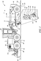
FIG. 1 is an exemplary machine having an implement assembly, in accordance with an embodiment of the present disclosure; -
FIG. 2 is a view of the implement assembly ofFIG. 1 , depicted as a snow plow assembly, and having an exemplary implement in a rearward tipped state, in accordance with an embodiment of the present disclosure; -
FIG. 3 is a view of the implement assembly ofFIG. 1 , with the implement in a forward tipped state, in accordance with an embodiment of the present disclosure; -
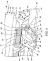
FIG. 4 is a perspective view of a wear pad assembly coupled to the implement ofFIG. 1 , in accordance with an embodiment of the present disclosure; -
FIG. 5 is an exploded view of the wear pad assembly ofFIG. 4 , in accordance with an embodiment of the present disclosure; and -
FIG. 6 is a perspective view of a wear pad assembly coupled to the implement ofFIG. 1 , in accordance with an alternate embodiment of the present disclosure. - Reference will now be made in detail to the preferred embodiments of the present disclosure, examples of which are illustrated in the accompanying drawings. Wherever possible, the same reference numbers will be used throughout the drawings to refer to the same or like parts.
- Referring to
FIG. 1 , anexemplary machine 100 is shown. Themachine 100 is a motor grader. However, it is possible for themachine 100 to embody other machines, such as a pick-up truck, a dozer, a loader, etc. Themachine 100 may be used to scrape, remove, and castmaterial 102, piled atop awork surface 104, towards one or both sides of thework surface 104. Thematerial 102 may include snow, although it is possible for thematerial 102 to include rocks, sand, soil, rubble, gravel, debris, other disintegrated particles, etc. Thework surface 104 may be a roadway, although an application of the aspects of the present disclosure may be contemplated over various other work surfaces, such as a pavement, a surface of a parking lot, etc. - Generally, the aforementioned functions of scraping, removing, and
casting material 102 is performed during machine movement, and for enabling machine movement, themachine 100 may includetraction devices 110, such as wheels, as shown. For example, thetraction devices 110 include a set offorward wheels 116 disposed towards aforward end 118 of themachine 100 and a set ofrearward wheels 120 disposed towards arearward end 122 of themachine 100. The terms 'forward' and 'rearward', as used herein, are in relation to a direction of travel of themachine 100, as represented by arrow, T, inFIG. 1 , with said direction of travel being exemplarily defined and visualized from therearward end 122 towards theforward end 118. Further, thetraction devices 110 may be powered by a power source, such as an internal combustion engine (not shown), housed in apower compartment 124 of themachine 100. Themachine 100 may include aframe 130 and anoperator cab 132. Theoperator cab 132 may be supported on theframe 130 and may house controls associated with the power source and various other functions of themachine 100. - The
machine 100 may include a variety of components including adrawbar 140, acircle 142, a tippingactuator 144, and animplement assembly 146. Each of thedrawbar 140, thecircle 142, and the tippingactuator 144, may function in concert or independently to manipulate theimplement assembly 146 in one or more orientations for casting thematerial 102 to the sides of thework surface 104. For example, thedrawbar 140 may be used to raise and lower theimplement assembly 146, thecircle 142 may be used to rotate the implement assembly 146 (about a vertical axis 148), and thetipping actuator 144 may enable theimplement assembly 146 to be tipped forward or rearward relative to the machine 100 (FIG. 2 exemplarily depicts theimplement assembly 146 in a rearward tipped state, whileFIG. 3 exemplarily depicts theimplement assembly 146 in a forward tipped state). Although theimplement assembly 146 is shown to be operably accommodated between the set offorward wheels 116 and the set ofrearward wheels 120 inFIG. 1 , it is possible for theimplement assembly 146 to be mounted to theforward end 118 of themachine 100, at which place a connection to thedrawbar 140 and to thecircle 142 may be unwarranted and non-existent. Moreover, an application of theimplement assembly 146 to other machines, such as to a pick-up truck, may include theimplement assembly 146 being mounted to a foremost end of such machines. It will be appreciated, therefore, that a positioning of theimplement assembly 146 is purely exemplary. Further, in some embodiments, theimplement assembly 146 may be configured to scrape, plow, and remove snow from thework surface 104, and thus, theimplement assembly 146 may be interchangeably referred to as a snow plow assembly 146'. - Referring to
FIGS 1 ,2 , and3 , theimplement assembly 146 includes animplement 150. The implement 150 includes aforward face 152 configured to receive, engage, and castmaterial 102 sideways, during a forward movement (arrow, T,FIG. 1 ) of themachine 100 over thework surface 104. The implement 150 also includes arearward face 154 that is opposite to theforward face 152. The implement 150 includes amoldboard portion 160 and ablade portion 162. As shown, themoldboard portion 160 and theblade portion 162 may be hinged to one another via a hinged mechanism 166 (the hingedmechanism 166 may also be visualized inFIGS. 4 and6 ). The hingedmechanism 166 may include afirst hinge 170 coupled to themoldboard portion 160 and asecond hinge 172 coupled to theblade portion 162. In an embodiment, thefirst hinge 170 and thesecond hinge 172 may be both coupled to the same face (i.e., to the rearward face 154) of the implement 150. Thefirst hinge 170 and thesecond hinge 172 may be pivotably coupled to each other, in turn enabling themoldboard portion 160 to be hinged relative to theblade portion 162. Further, the hingedmechanism 166 may include abiasing unit 176, as shown inFIG. 4 , that may help theblade portion 162 retain a leading, scrapingedge 178 against theunderlying material 102 of thework surface 104, during a movement of themachine 100 over thework surface 104. In some embodiments, themoldboard portion 160 and theblade portion 162 may be integrally formed to define a fixed implement or a fixed blade, and, in such cases, the hingedmechanism 166 may be absent. Accordingly, a configuration of the implement 150 and the details of the hingedmechanism 166 are all purely exemplary as well. Therefore, all possible equivalents of the implement 150, including buckets, material pushers, etc., may also utilize one or more of the aspects discussed herein, without departing from the scope and spirit of the present disclosure. - Referring to
FIGS. 1 ,2 ,3 ,4 , and5 , the implementassembly 146 is discussed. The implementassembly 146 includes awear pad assembly 190 for the implement 150. Thewear pad assembly 190 is assembled in proximity to thescraping edge 178 of theblade portion 162, and is configured to contact thework surface 104, during operation. Thewear pad assembly 190 prevents premature wear of thescraping edge 178 and mitigates damage to theunderlying work surface 104. Thewear pad assembly 190 includes afirst bracket 192, asecond bracket 194, awear pad 196, a biasingmember 198, apin 200,first fasteners 202, 202', andsecond fasteners 204, 204'. - Referring to
FIG. 5 , thefirst bracket 192 includes a pair of spaced apart sidewalls 210, 210' (or simply,first sidewalls 210, 210') and abase wall 212 that connects to and extends between thefirst sidewalls 210, 210'. As an example, thefirst sidewalls 210, 210' may be perpendicular to thebase wall 212, and may be structured and arranged relative to thebase wall 212 to impart a U-shaped profile to thefirst bracket 192. In some embodiments, thefirst bracket 192 may be formed from a single piece of sheet metal that have opposed end portions bent in the same direction, so as to define the U-shaped profile of thefirst bracket 192, and thus to also define thebase wall 212 and thefirst sidewalls 210, 210' of thefirst bracket 192. Alternatively, thefirst bracket 192 may be formed by welding two or more plates together. For example, similarly sized end plates may be abutted and welded to opposed edges of a base plate. Together, the similarly sized end plates and the base plate may impart the U-shaped profile to thefirst bracket 192, and may also define thebase wall 212 and thefirst sidewalls 210, 210' of thefirst bracket 192. Each of thefirst sidewalls 210, 210' include a first aperture (seefirst apertures 214, 214' annotated respectively forfirst sidewalls 210, 210'). Thefirst aperture 214 of onefirst sidewall 210 may be co-axially aligned with the first aperture 214' of the other first sidewall 210'. Thefirst sidewalls 210, 210' may define a distance, D1, between each other, and, moreover, each of thefirst sidewalls 210, 210' may include a thickness, T1. - Further, the
base wall 212 may be configured to be fixedly coupled to therearward face 154 of the implement 150. As an example, thebase wall 212 of thefirst bracket 192 is affixed to the second hinge 172 (seeFIG. 4 ) that is in turn coupled to therearward face 154 of the implement 150, as shown. In some embodiments, thebase wall 212 of thefirst bracket 192 includesopenings 216, 216', and is coupled and secured to thefirst hinge 170 by way offirst fasteners 202, 202' that may be respectively passed through theopenings 216, 216' and be secured to thebase wall 212 by way ofnuts 218, 218'.First fasteners 202, 202' may include threaded fasteners, such as bolts. In cases where a usage of the hingedmechanism 166 is absent, thebase wall 212 of thefirst bracket 192 may be directly coupled to therearward face 154 of the implement 150. - The
second bracket 194 is pivotably coupled to thefirst bracket 192. As with thefirst bracket 192, thesecond bracket 194 includes a pair of spaced apart sidewalls 230, 230' (or simplysecond sidewalls 230, 230') and abase wall 232 that connects to and extends between thesecond sidewalls 230, 230'. Moreover, thesecond sidewalls 230, 230' may be perpendicular to thebase wall 232, as well, and may be structured and arranged to impart a U-shaped profile to thesecond bracket 194. Alike thefirst bracket 192, in some embodiments, thesecond bracket 194 may be formed from a single piece of sheet metal that have opposed end portions bent in the same direction to define the U-shaped profile of thesecond bracket 194, and thus to also define thebase wall 232 and thesecond sidewalls 230, 230'. Alternatively, and as discussed for thefirst bracket 192, thesecond bracket 194 may be formed by welding two or more plates together, as well. For example, similarly sized end plates may be abutted and welded to opposed edges of a base plate. Together, the similarly sized end plates and the base plate may impart the U-shaped profile to thesecond bracket 194, and may also define thebase wall 232 and thesecond sidewalls 230, 230' of thesecond bracket 194. Each of thesecond sidewalls 230, 230' include a second aperture (seesecond apertures second aperture 234 of onesecond sidewall 230 may be co-axially aligned with the second aperture 234' of the other second sidewall 230'. Thesecond sidewalls 230, 230' may define a distance, D2, between each other, and, moreover, each of thesecond sidewalls 230, 230' may include a thickness, T2. Further, thebase wall 232 may includeopenings 236, 236' that may respectively receive thesecond fasteners 204, 204' for securing thewear pad 196 to thebase wall 232. As with thefirst fasteners 202, 202', thesecond fasteners 204, 204' may include threaded fasteners, such as bolts, as well. - In some embodiments, the distance, D2, combined with thicknesses, T2, of the
second sidewalls 230, 230', may be smaller than the distance, D1, defined between thefirst sidewalls 210, 210' (i.e., D2 + T2 + T2 < D1). In that way, thesecond sidewalls 230, 230' of thesecond bracket 194 may be inserted in between thefirst sidewalls 210, 210' of thefirst bracket 192, for an assembly of thesecond bracket 194 to thefirst bracket 192. In some embodiments, the distance, D2, summated with thicknesses, T2, of thesecond sidewalls 230, 230' may together span the entire distance, D1. In so doing, thesecond sidewalls 230, 230' may sit substantially flush against thefirst sidewalls 210, 210', and an assembly of thesecond bracket 194 to thefirst bracket 192 may be attained with minimum (or negligible) play. In an assembly of thesecond bracket 194 to thefirst bracket 192, thesecond apertures 234, 234' may be co-axially aligned with thefirst apertures 214, 214'. Further, as an example, a first pivot joint 240 (seeFIGS. 4 and6 ) is defined by onefirst sidewall 210 and onesecond sidewall 230, while a second pivot joint 240' (seeFIGS. 4 and6 ) is defined by the other first sidewall 210' and the other second sidewall 230'. - Alternatively, and depending upon certain factors, such as spatial constraints, operational conditions, and/or other requirements, it is possible for the
second bracket 194 to fit outside of thefirst bracket 192. In such a case, the distance, D1, summated with thicknesses, T1, of thefirst sidewalls 210, 210' may be smaller than distance, D2 (i.e., D1 + T1 + T1 < D2) and, accordingly, thefirst bracket 192 may sit within thesecond bracket 194, in turn allowing thesecond bracket 194 to fit outside of thefirst bracket 192. In some embodiments, the distance, D1, summated with thicknesses, T1, of thefirst sidewalls 210, 210' may together span the entire distance, D2, and accordingly, an assembly of thefirst bracket 192 within thesecond bracket 194 may be attained with minimum (or negligible) play. - The
wear pad 196 is coupled to thesecond bracket 194, and is thereby pivotably coupled to therearward face 154 of the implement 150, and is also configured to contact thework surface 104 during operation. Although not limited, thewear pad 196 may include a shape and dimension that is compliant with a shape and dimension of thebase wall 232 of thesecond bracket 194. Thewear pad 196 may include aflat bottom surface 242 that may be configured to engage thework surface 104, during operation. Thewear pad 196 may include a sacrificial wear component made from one or more of a number of materials, including, but not limited to, polymer, nylon, ceramic, a metallic material, or any low friction material, that may help thewear pad 196 slide relative to thework surface 104. Further,openings 246, 246' may be formed in thewear pad 196 through which thesecond fasteners 204, 204' may be passed for a securement of thewear pad 196 to thebase wall 232 of thesecond bracket 194. - Optionally, one or more shims (see shim 250) may be added to the
wear pad assembly 190, for a placement between thewear pad 196 and thebase wall 232 of thesecond bracket 194. In so doing, a spacing between thebase wall 232 of thesecond bracket 194 and thewear pad 196 may be adjusted, if needed. For example, theshim 250 may includeopenings 254, 254' that align respectively with theopenings 246, 246' of thewear pad 196, and respectively withopenings 236, 236' of thebase wall 232. Thesecond fastener 204 may be driven and secured through the alignedopenings nuts 258, 258' may be respectively coupled to thesecond fasteners 204, 204' to retain thewear pad 196 and theshim 250 with thebase wall 232. - The
pin 200 may be used to pivotably couple thefirst bracket 192 to thesecond bracket 194. For example, thepin 200 may be inserted and passed through both thefirst apertures 214, 214' and thesecond apertures 234, 234', respectively, for pivotably securing thefirst bracket 192 to thesecond bracket 194, and thereby defining the first pivot joint 240 and the second pivot joint 240'. Thepin 200 may include ahead portion 260 at one end and aslot 262 at the other end. In an assembled state of thefirst bracket 192 with thesecond bracket 194, thehead portion 260 may be abutted against the first sidewall 210', as shown, while theslot 262 may extend beyond thefirst sidewall 210, thereby jutting outwardly of the assembly of thefirst bracket 192 and thesecond bracket 194. Aretainer pin 270 may be passed through theslot 262 to retentively couple thepin 200 to the assembly of thefirst bracket 192 and thesecond bracket 194, which in turn enables thepin 200 to pivotably couple and retain thesecond bracket 194 to thefirst bracket 192. Additionally, or optionally, one or morefirst washers 272 may be applied between thefirst sidewall 210 and theretainer pin 270, and, similarly, one or more second washers 272' may be applied between thehead portion 260 and the first sidewall 210'. Further, thepin 200 may define apivot axis 280 about which thesecond bracket 194 may be pivoted relative to thefirst bracket 192. - The biasing
member 198 may be configured to bias thesecond bracket 194 away from thefirst bracket 192. More particularly, the biasingmember 198 may be engaged with thesecond bracket 194 and configured to bias thewear pad 196 in abutment with thework surface 104 during use of the implement 150. Exemplarily, the biasingmember 198 may include ablock 290 formed from a non-metallic compressible material. Theblock 290 may include a generally cuboidal shape with atop face 292, abottom face 294, and a side face 296 (or an inner side face 296) extending between thetop face 292 and thebottom face 294. Theblock 290 also includes anouter side face 298 opposite to theinner side face 296, and two oppositely defined, similarly laid out lateral faces. As an example, only onelateral face 300 is exclusively shown in the figures. The otherlateral face 302 may be visualized as being similar and oppositely disposed to thelateral face 300. Discussions pertaining to thelateral face 300 will be applicable to the other, oppositely disposedlateral face 302, as well. - The
lateral face 300 extends to each of theouter side face 298, theinner side face 296, thebottom face 294, and thetop face 292. Theinner side face 296 extends from thebottom face 294 at an angle to thebottom face 294. In one example, the angle between thebottom face 294 and theinner side face 296 is 90 degrees. In another example, an angle between theinner side face 296 and thebottom face 294 includes an obtuse angle. In yet other examples, an angle between theinner side face 296 and thebottom face 294 is a function of, or is equal to a maximum attainable angle between thefirst bracket 192 and thesecond bracket 194 about thepivot axis 280. In an assembly of thesecond bracket 194 with thefirst bracket 192, theinner side face 296 may be abutted (or coupled) to the first bracket 192 (i.e., to thebase wall 212 of the first bracket 192), while thebottom face 294 may be abutted (or coupled) to the second bracket 194 (i.e., to thebase wall 232 of the second bracket 194). During operation, force may be applied against theinner side face 296 by thefirst bracket 192, and in response, theinner side face 296 may be angularly compressed towards the bottom face 294 (owing to a pivotal motion between thefirst bracket 192 and the second bracket 194), thereby biasing thesecond bracket 194 away from thefirst bracket 192. - In some embodiments, and as shown, the
top face 292 of theblock 290 includes asloping roof portion 310. Thesloping roof portion 310 may form an interface extending between theouter side face 298 and thetop face 292, and may be tilted to each of theouter side face 298 and thetop face 292. For example, the slopingroof portion 310 extends from thetop face 292 and is inclined towards thebottom face 294. In some embodiments, however, thetop face 292 and theouter side face 298 may be non-existent, and thesloping roof portion 310 may extend directly from theinner side face 296 to thebottom face 294, thereby imparting a triangular configuration to theblock 290. Further, theblock 290 includes a through-hole 312 extending through and across theblock 290, from thelateral face 300 to the oppositely disposed, otherlateral face 302. The through-hole 312 may provide passage for thepin 200 to be disposed through theblock 290. In that way, the block 290 (and thus the biasing member 198) may be engaged with thepin 200, and thus theblock 290 may be retained between thefirst bracket 192 and thesecond bracket 194. As an example, theblock 290 is formed from Polyurethane. However, it is possible for other materials, such as polymers, rubber, etc., singularly or in combination with each other, to be applied for the formation of the block 290 (or the biasing member 198). - Referring to
FIG. 6 , in yet some embodiments, theblock 290 is omitted, and instead, a torsion spring 290' is assembled around thepin 200, and is thus engaged with thepin 200 for application as the biasingmember 198 between thefirst bracket 192 and thesecond bracket 194. As shown, the torsion spring 290' may include oneend 320 in engagement with thebase wall 212 of thefirst bracket 192, while anotherend 322 in engagement with thebase wall 232 of thesecond bracket 194, biasing thesecond bracket 194 away from thefirst bracket 192. Further alternatives of the biasingmember 198 may be contemplated as well. - During operation, the
machine 100 is driven through thematerial 102, so as to clear the material piled over thework surface 104. Depending upon a variety of conditions, such as a state of the material (i.e., whether the material is soft or hard), or a fragility of thework surface 104, environmental factors, operational parameters, etc., it is possible for the implement 150 (and thus thescraping edge 178 of the blade portion 162) to be moved to the forward tipped state (seeFIG. 3 ) or to the rearward tipped state (seeFIG. 2 ), relative to themachine 100. It may be noted that in both the forward tipped state (seeFIG. 3 ) and in the rearward tipped state (seeFIG. 2 ), thewear pad 196 may be in contact with thework surface 104. - Upon a movement of the implement 150 from the forward tipped state (see
FIG. 3 ) to the rearward tipped state (seeFIG. 2 ), thefirst bracket 192 angularly moves towards thesecond bracket 194. During the angular movement (and if theblock 290 were applied as the biasingmember 198 between thefirst bracket 192 and the second bracket 194), thefirst bracket 192 may exert a force against theinner side face 296 of theblock 290, compress and deform theblock 290, and may transmit the force to thesecond bracket 194 through thebottom face 294 of theblock 290. This biasing force helps the second bracket 194 (and thus the wear pad 196) stay in uninterrupted abutment with thework surface 104 throughout the movement of the implement 150 from the forward tipped state (seeFIG. 3 ) to the rearward tipped state (seeFIG. 2 ). The biasing force of the biasingmember 198 also keeps thewear pad 196 in abutment with thework surface 104 when the implement 150 is in the rearward tipped state (seeFIG. 2 ). With such a mechanism, thewear pad assembly 190 refrains from moving or gouging into/under thework surface 104, and refrains from extending below thescraping edge 178 of theblade portion 162. Moreover, the implement 150 (and thescraping edge 178 of the implement 150) also remains engaged with thework surface 104 in the rearward tipped state (seeFIG. 2 ), leaving substantially no room for any layer ofmaterial 102 to remain unaltered and/or unplowed. - Conversely, when a movement of the implement 150 is executed from the rearward tipped state (see
FIG. 2 ) to the forward tipped state (seeFIG. 3 ), the biasing member 198 (such as the block 290) is released from compression, and thefirst bracket 192 angularly moves away from thesecond bracket 194. Throughout the movement of the implement 150 from the rearward tipped state (seeFIG. 2 ) to the forward tipped state (seeFIG. 3 ), the biasingmember 198 may continue to offer the biasing force to maintain thewear pad 196 in uninterrupted abutment with thework surface 104. The biasing force of the biasingmember 198 may also keep thewear pad 196 in abutment with thework surface 104 when the implement 150 is in the forward tipped state (seeFIG. 3 ). - An application of the torsion spring 290' may be similar to the application of the
block 290, as discussed above. Further, the application of thewear pad assembly 190, according to aspects of the present disclosure, helps overcome one pertinent drawback, among many others, of a conventional practice that involved an application of a fixed wear pad assembly. Application of a fixed wear pad assembly may gouge a relatively fragile, delicate underlying work surface, or may engage and undesirably raise an associated implement above a work surface, hampering material altering (such as snow plowing) operations. With the use of thewear pad assembly 190, as discussed herein, thework surface 104 is effectively kept from damage, and a vulnerability for thescraping edge 178 of theblade portion 162 to be unduly raised above thework surface 104, entailing thatmaterial 102 may be left unaltered and/or unplowed, is substantially mitigated. Further, since thewear pad assembly 190 may automatically adjust according to a position of the implement 150, a need to repeatedly adjust and/or remove thewear pad 196 for different applications may be avoided. The automatic adjustment of thewear pad assembly 190, as discussed, also reduces effort associated with manual wear pad adjustments. - It will be apparent to those skilled in the art that various modifications and variations can be made to the system of the present disclosure without departing from the scope of the disclosure. Other embodiments will be apparent to those skilled in the art from consideration of the specification and practice of the system disclosed herein. It is intended that the specification and examples be considered as exemplary only, with a true scope of the disclosure being indicated by the following claims and their equivalent.
Claims (20)
- A wear pad assembly for an implement of a machine, the implement including a forward face configured to engage and cast material sideways during a forward movement of the machine over a work surface, and a rearward face opposite the forward face, the wear pad assembly comprising:a first bracket configured to be fixedly coupled to the rearward face of the implement;a second bracket pivotably coupled to the first bracket;a wear pad coupled to the second bracket and configured to contact the work surface; anda biasing member engaged with the second bracket and configured to bias the wear pad in abutment with the work surface during use of the implement.
- The wear pad assembly of claim 1 further including a pin passing through the first bracket and the second bracket to pivotably couple the first bracket to the second bracket.
- The wear pad assembly of claim 2, wherein the biasing member is engaged with the pin.
- The wear pad assembly of claim 2, wherein each of the first bracket and the second bracket includes a pair of spaced apart sidewalls and a base wall extending between the pair of spaced apart sidewalls, wherein:the base wall of the first bracket is configured to be fixedly coupled to the rearward face of the implement,the base wall of the second bracket is coupled to the wear pad, andthe pin passes through the pair of spaced apart sidewalls to pivotably couple the second bracket to the first bracket.
- The wear pad assembly of claim 1, wherein the biasing member includes a block formed from a non-metallic compressible material, and includes a side face abutted against the first bracket and a bottom face abutted against the second bracket.
- The wear pad assembly of claim 1, wherein the biasing member is formed from Polyurethane.
- The wear pad assembly of claim 1, wherein the biasing member includes a torsion spring.
- An implement assembly for a machine, the implement assembly comprising:an implement configured to travel between a forward tipped state and a rearward tipped state relative to the machine, the implement including:a forward face configured to engage and cast material sideways during a forward movement of the machine over a work surface, anda rearward face opposite the forward face;a wear pad pivotably coupled to the rearward face of the implement, and configured to contact the work surface; anda biasing member configured to bias and keep the wear pad in abutment with the work surface when the implement is in the forward tipped state and the rearward tipped state.
- The implement assembly of claim 8 further including:a first bracket configured to be fixedly coupled to the rearward face of the implement; anda second bracket pivotably coupled to the first bracket, wherein:the wear pad is coupled to the second bracket.
- The implement assembly of claim 9 further including a pin passing through the first bracket and the second bracket to pivotably couple the first bracket to the second bracket, and thereby pivotably coupling the wear pad to the rearward face of the implement.
- The implement assembly of claim 10, wherein each of the first bracket and the second bracket includes a pair of spaced apart sidewalls and a base wall extending between the pair of spaced apart sidewalls, wherein:the base wall of the first bracket is configured to be fixedly coupled to the rearward face of the implement,the base wall of the second bracket is coupled to the wear pad, andthe pin passes through the pair of spaced apart sidewalls to pivotably couple the second bracket to the first bracket.
- The implement assembly of claim 9, wherein the biasing member includes a block formed from a non-metallic compressible material, and includes a side face abutted against the first bracket and a bottom face abutted against the second bracket.
- The implement assembly of claim 8, wherein the biasing member is formed from Polyurethane.
- The implement assembly of claim 8, wherein the biasing member includes a torsion spring.
- A snow plow assembly for a machine, the snow plow assembly comprising:an implement configured to travel between a forward tipped state and a rearward tipped state relative to the machine, the implement including:a forward face configured to engage and cast material sideways during a forward movement of the machine over a work surface, anda rearward face opposite the forward face;a first bracket fixedly coupled to the rearward face of the implement;a second bracket pivotably coupled to the first bracket;a wear pad coupled to the second bracket and configured to contact the work surface; anda biasing member engaged with the second bracket and configured to bias the second bracket to keep the wear pad in abutment with the work surface when the implement is in the forward tipped state and the rearward tipped state.
- The snow plow assembly of claim 15 further including a pin passing through the first bracket and the second bracket to pivotably couple the first bracket to the second bracket.
- The snow plow assembly of claim 16, wherein each of the first bracket and the second bracket includes a pair of spaced apart sidewalls and a base wall extending between the pair of spaced apart sidewalls, wherein:the base wall of the first bracket is configured to be fixedly coupled to the rearward face of the implement,the base wall of the second bracket is coupled to the wear pad, andthe pin passes through the pair of spaced apart sidewalls to pivotably couple the second bracket to the first bracket.
- The snow plow assembly of claim 16, wherein the biasing member is engaged with the pin.
- The snow plow assembly of claim 15, wherein the biasing member includes a block formed from a non-metallic compressible material, and includes a side face abutted against the first bracket and a bottom face abutted against the second bracket.
- The snow plow assembly of claim 15, wherein the biasing member includes a torsion spring.
Applications Claiming Priority (1)
| Application Number | Priority Date | Filing Date | Title |
|---|---|---|---|
| US15/883,150 US10851509B2 (en) | 2018-01-30 | 2018-01-30 | Wear pad assembly for implements of machines |
Publications (2)
| Publication Number | Publication Date |
|---|---|
| EP3524735A1 true EP3524735A1 (en) | 2019-08-14 |
| EP3524735B1 EP3524735B1 (en) | 2024-04-10 |
Family
ID=65010652
Family Applications (1)
| Application Number | Title | Priority Date | Filing Date |
|---|---|---|---|
| EP19150863.9A Active EP3524735B1 (en) | 2018-01-30 | 2019-01-08 | Wear pad assembly for implements of machines |
Country Status (3)
| Country | Link |
|---|---|
| US (1) | US10851509B2 (en) |
| EP (1) | EP3524735B1 (en) |
| CA (1) | CA3031492A1 (en) |
Families Citing this family (5)
| Publication number | Priority date | Publication date | Assignee | Title |
|---|---|---|---|---|
| EP3940145B1 (en) | 2020-07-16 | 2024-03-27 | Gestion Pihm Inc. | Sweeping blade device and sweeping blade assembly for a vehicle |
| US11697911B2 (en) | 2020-09-04 | 2023-07-11 | Venture Products, Inc. | V-shaped snowplow blade having trip edges |
| US11708672B2 (en) * | 2020-09-04 | 2023-07-25 | Venture Products, Inc. | V-shaped snowplow blade with trip edge and pivotable snow shield |
| US11619016B2 (en) | 2020-09-04 | 2023-04-04 | Venture Products, Inc. | Multi-position snowplow blade with translatable trip edge |
| CN114703912B (en) * | 2022-05-05 | 2023-08-25 | 中铁三局集团天津建设工程有限公司 | Roadbed slope arch skeleton grooving machine and construction method thereof |
Citations (4)
| Publication number | Priority date | Publication date | Assignee | Title |
|---|---|---|---|---|
| DE29500723U1 (en) * | 1995-01-18 | 1995-03-09 | Gießler, Matthias, 77933 Lahr | Snow plow with swivel flap scraper |
| WO2013174228A1 (en) * | 2012-05-21 | 2013-11-28 | Zhang Yupeng | Improved striking sheet of icebreaking rod |
| US8776405B2 (en) | 2006-11-17 | 2014-07-15 | Adepco Technologies, Corp. | Snow plow for adjusting to surface contours and obstacles |
| US9528234B1 (en) * | 2016-05-24 | 2016-12-27 | Equipement Vtc Mfg Inc | Front retracting plow with sliding blade sections |
Family Cites Families (13)
| Publication number | Priority date | Publication date | Assignee | Title |
|---|---|---|---|---|
| US2651121A (en) * | 1948-06-25 | 1953-09-08 | Four Wheel Drive Auto Company | Apparatus for high-speed snow removal without windrowing |
| US2695465A (en) | 1948-12-14 | 1954-11-30 | Dominion Road Machinery Co Ltd | Snowplow |
| US2756522A (en) * | 1952-04-28 | 1956-07-31 | Bomford & Evershed Ltd | Attachments for vehicles for traversing heaped up material along the ground |
| US2794273A (en) * | 1952-07-02 | 1957-06-04 | Bomford & Evershed Ltd | Attachments for vehicles for traversing heaped up material along the ground |
| US3217431A (en) * | 1963-03-21 | 1965-11-16 | Good Roads Machinery Corp | Shoes for snowplows and the like |
| US4450635A (en) * | 1982-09-24 | 1984-05-29 | Shwayder Warren M | Level adjustable skid shoe for plow blades |
| US4607781A (en) * | 1985-01-24 | 1986-08-26 | Shwayder Warren M | Method of manufacturing an adjustable mounting snow plow skid shoes |
| US5185946A (en) * | 1990-04-23 | 1993-02-16 | Farrell Eugene A | Plow assembly with flexible moldboard |
| US5140763A (en) * | 1991-02-11 | 1992-08-25 | Nichols Iv Charles W | Snow removal apparatus |
| US6352126B1 (en) * | 2000-04-10 | 2002-03-05 | Dennis A. Brown | Finish dirt scraper with improved damping device |
| US7143531B2 (en) * | 2004-07-02 | 2006-12-05 | Micozzi Albert M | Plow protector |
| US7543401B2 (en) * | 2007-08-17 | 2009-06-09 | Doug Hughes | Back drag plow |
| US9243376B2 (en) | 2013-06-14 | 2016-01-26 | Pro-Tech Manufacturing And Distribution, Inc. | Surface compliant front-pivoting wear shoes for snow pusher |
-
2018
- 2018-01-30 US US15/883,150 patent/US10851509B2/en active Active
-
2019
- 2019-01-08 EP EP19150863.9A patent/EP3524735B1/en active Active
- 2019-01-25 CA CA3031492A patent/CA3031492A1/en active Pending
Patent Citations (4)
| Publication number | Priority date | Publication date | Assignee | Title |
|---|---|---|---|---|
| DE29500723U1 (en) * | 1995-01-18 | 1995-03-09 | Gießler, Matthias, 77933 Lahr | Snow plow with swivel flap scraper |
| US8776405B2 (en) | 2006-11-17 | 2014-07-15 | Adepco Technologies, Corp. | Snow plow for adjusting to surface contours and obstacles |
| WO2013174228A1 (en) * | 2012-05-21 | 2013-11-28 | Zhang Yupeng | Improved striking sheet of icebreaking rod |
| US9528234B1 (en) * | 2016-05-24 | 2016-12-27 | Equipement Vtc Mfg Inc | Front retracting plow with sliding blade sections |
Also Published As
| Publication number | Publication date |
|---|---|
| EP3524735B1 (en) | 2024-04-10 |
| CA3031492A1 (en) | 2019-07-30 |
| US20190234034A1 (en) | 2019-08-01 |
| US10851509B2 (en) | 2020-12-01 |
Similar Documents
| Publication | Publication Date | Title |
|---|---|---|
| EP3524735A1 (en) | Wear pad assembly for implements of machines | |
| US7360327B2 (en) | Material moving pusher/bucket | |
| US9133599B2 (en) | Skid device attachable to a bucket, bucket assembly for moving material, and method of forming the skid device | |
| US5967241A (en) | ATV lift handle | |
| US6314666B1 (en) | Material moving blade | |
| US7832127B2 (en) | Apparatus for attaching a work tool to a loader | |
| CN110080320B (en) | Surface forming apparatus and motorized surface forming apparatus | |
| GB2303865A (en) | Replaceable wear runner | |
| US6487799B2 (en) | Removable hitch attachment for earth-moving equipment | |
| US20170298583A1 (en) | Folding wing plow | |
| US12116739B2 (en) | Skid device attachable to loader bucket, loader bucket assembly for moving material, and method thereof | |
| US4407081A (en) | Bucket tooth attachment means | |
| CA3134279C (en) | Side panel assembly for a snow plow | |
| CN101158166A (en) | External end plate gussets for pusher attachments | |
| EP2911237B1 (en) | Receiver assembly | |
| US10549798B2 (en) | Vehicle track cleaner | |
| US5901793A (en) | Apparatus and method for automatically adjusting the pitch of a dozer blade | |
| US20010037588A1 (en) | Bucket with quick attach blade | |
| RU2202675C2 (en) | Snow cleaner cutting blade holder | |
| US7337564B2 (en) | Loader coupler or other attachment with adjustable stops | |
| US9366006B2 (en) | Bucket for work vehicle, and work vehicle equipped with bucket with left and right boom attachment portions | |
| CN205000380U (en) | A machines system for machine | |
| US20250154742A1 (en) | Grader machine including moldboard mounting assembly with bump stops | |
| CA2632026C (en) | Apparatus protecting vehicle with accessory when scraping edge of accessory strikes fixed object | |
| RU2379427C1 (en) | Alignment accessory for snap-change devices |
Legal Events
| Date | Code | Title | Description |
|---|---|---|---|
| PUAI | Public reference made under article 153(3) epc to a published international application that has entered the european phase |
Free format text: ORIGINAL CODE: 0009012 |
|
| STAA | Information on the status of an ep patent application or granted ep patent |
Free format text: STATUS: THE APPLICATION HAS BEEN PUBLISHED |
|
| AK | Designated contracting states |
Kind code of ref document: A1 Designated state(s): AL AT BE BG CH CY CZ DE DK EE ES FI FR GB GR HR HU IE IS IT LI LT LU LV MC MK MT NL NO PL PT RO RS SE SI SK SM TR |
|
| AX | Request for extension of the european patent |
Extension state: BA ME |
|
| STAA | Information on the status of an ep patent application or granted ep patent |
Free format text: STATUS: REQUEST FOR EXAMINATION WAS MADE |
|
| 17P | Request for examination filed |
Effective date: 20200212 |
|
| RBV | Designated contracting states (corrected) |
Designated state(s): AL AT BE BG CH CY CZ DE DK EE ES FI FR GB GR HR HU IE IS IT LI LT LU LV MC MK MT NL NO PL PT RO RS SE SI SK SM TR |
|
| STAA | Information on the status of an ep patent application or granted ep patent |
Free format text: STATUS: EXAMINATION IS IN PROGRESS |
|
| 17Q | First examination report despatched |
Effective date: 20210625 |
|
| GRAP | Despatch of communication of intention to grant a patent |
Free format text: ORIGINAL CODE: EPIDOSNIGR1 |
|
| STAA | Information on the status of an ep patent application or granted ep patent |
Free format text: STATUS: GRANT OF PATENT IS INTENDED |
|
| INTG | Intention to grant announced |
Effective date: 20231002 |
|
| GRAS | Grant fee paid |
Free format text: ORIGINAL CODE: EPIDOSNIGR3 |
|
| GRAA | (expected) grant |
Free format text: ORIGINAL CODE: 0009210 |
|
| STAA | Information on the status of an ep patent application or granted ep patent |
Free format text: STATUS: THE PATENT HAS BEEN GRANTED |
|
| P01 | Opt-out of the competence of the unified patent court (upc) registered |
Effective date: 20240213 |
|
| AK | Designated contracting states |
Kind code of ref document: B1 Designated state(s): AL AT BE BG CH CY CZ DE DK EE ES FI FR GB GR HR HU IE IS IT LI LT LU LV MC MK MT NL NO PL PT RO RS SE SI SK SM TR |
|
| REG | Reference to a national code |
Ref country code: GB Ref legal event code: FG4D |
|
| REG | Reference to a national code |
Ref country code: CH Ref legal event code: EP |
|
| REG | Reference to a national code |
Ref country code: DE Ref legal event code: R096 Ref document number: 602019049837 Country of ref document: DE |
|
| REG | Reference to a national code |
Ref country code: IE Ref legal event code: FG4D |
|
| REG | Reference to a national code |
Ref country code: LT Ref legal event code: MG9D |
|
| REG | Reference to a national code |
Ref country code: NL Ref legal event code: MP Effective date: 20240410 |
|
| REG | Reference to a national code |
Ref country code: AT Ref legal event code: MK05 Ref document number: 1675041 Country of ref document: AT Kind code of ref document: T Effective date: 20240410 |
|
| PG25 | Lapsed in a contracting state [announced via postgrant information from national office to epo] |
Ref country code: NL Free format text: LAPSE BECAUSE OF FAILURE TO SUBMIT A TRANSLATION OF THE DESCRIPTION OR TO PAY THE FEE WITHIN THE PRESCRIBED TIME-LIMIT Effective date: 20240410 |
|
| PG25 | Lapsed in a contracting state [announced via postgrant information from national office to epo] |
Ref country code: NL Free format text: LAPSE BECAUSE OF FAILURE TO SUBMIT A TRANSLATION OF THE DESCRIPTION OR TO PAY THE FEE WITHIN THE PRESCRIBED TIME-LIMIT Effective date: 20240410 |
|
| PG25 | Lapsed in a contracting state [announced via postgrant information from national office to epo] |
Ref country code: IS Free format text: LAPSE BECAUSE OF FAILURE TO SUBMIT A TRANSLATION OF THE DESCRIPTION OR TO PAY THE FEE WITHIN THE PRESCRIBED TIME-LIMIT Effective date: 20240810 |
|
| PG25 | Lapsed in a contracting state [announced via postgrant information from national office to epo] |
Ref country code: BG Free format text: LAPSE BECAUSE OF FAILURE TO SUBMIT A TRANSLATION OF THE DESCRIPTION OR TO PAY THE FEE WITHIN THE PRESCRIBED TIME-LIMIT Effective date: 20240410 |
|
| PG25 | Lapsed in a contracting state [announced via postgrant information from national office to epo] |
Ref country code: FI Free format text: LAPSE BECAUSE OF FAILURE TO SUBMIT A TRANSLATION OF THE DESCRIPTION OR TO PAY THE FEE WITHIN THE PRESCRIBED TIME-LIMIT Effective date: 20240410 Ref country code: HR Free format text: LAPSE BECAUSE OF FAILURE TO SUBMIT A TRANSLATION OF THE DESCRIPTION OR TO PAY THE FEE WITHIN THE PRESCRIBED TIME-LIMIT Effective date: 20240410 |
|
| PG25 | Lapsed in a contracting state [announced via postgrant information from national office to epo] |
Ref country code: GR Free format text: LAPSE BECAUSE OF FAILURE TO SUBMIT A TRANSLATION OF THE DESCRIPTION OR TO PAY THE FEE WITHIN THE PRESCRIBED TIME-LIMIT Effective date: 20240711 |
|
| PG25 | Lapsed in a contracting state [announced via postgrant information from national office to epo] |
Ref country code: PT Free format text: LAPSE BECAUSE OF FAILURE TO SUBMIT A TRANSLATION OF THE DESCRIPTION OR TO PAY THE FEE WITHIN THE PRESCRIBED TIME-LIMIT Effective date: 20240812 |
|
| PG25 | Lapsed in a contracting state [announced via postgrant information from national office to epo] |
Ref country code: ES Free format text: LAPSE BECAUSE OF FAILURE TO SUBMIT A TRANSLATION OF THE DESCRIPTION OR TO PAY THE FEE WITHIN THE PRESCRIBED TIME-LIMIT Effective date: 20240410 |
|
| PG25 | Lapsed in a contracting state [announced via postgrant information from national office to epo] |
Ref country code: AT Free format text: LAPSE BECAUSE OF FAILURE TO SUBMIT A TRANSLATION OF THE DESCRIPTION OR TO PAY THE FEE WITHIN THE PRESCRIBED TIME-LIMIT Effective date: 20240410 |
|
| PG25 | Lapsed in a contracting state [announced via postgrant information from national office to epo] |
Ref country code: PL Free format text: LAPSE BECAUSE OF FAILURE TO SUBMIT A TRANSLATION OF THE DESCRIPTION OR TO PAY THE FEE WITHIN THE PRESCRIBED TIME-LIMIT Effective date: 20240410 |
|
| PG25 | Lapsed in a contracting state [announced via postgrant information from national office to epo] |
Ref country code: LV Free format text: LAPSE BECAUSE OF FAILURE TO SUBMIT A TRANSLATION OF THE DESCRIPTION OR TO PAY THE FEE WITHIN THE PRESCRIBED TIME-LIMIT Effective date: 20240410 |
|
| PG25 | Lapsed in a contracting state [announced via postgrant information from national office to epo] |
Ref country code: PT Free format text: LAPSE BECAUSE OF FAILURE TO SUBMIT A TRANSLATION OF THE DESCRIPTION OR TO PAY THE FEE WITHIN THE PRESCRIBED TIME-LIMIT Effective date: 20240812 Ref country code: PL Free format text: LAPSE BECAUSE OF FAILURE TO SUBMIT A TRANSLATION OF THE DESCRIPTION OR TO PAY THE FEE WITHIN THE PRESCRIBED TIME-LIMIT Effective date: 20240410 Ref country code: NO Free format text: LAPSE BECAUSE OF FAILURE TO SUBMIT A TRANSLATION OF THE DESCRIPTION OR TO PAY THE FEE WITHIN THE PRESCRIBED TIME-LIMIT Effective date: 20240710 Ref country code: LV Free format text: LAPSE BECAUSE OF FAILURE TO SUBMIT A TRANSLATION OF THE DESCRIPTION OR TO PAY THE FEE WITHIN THE PRESCRIBED TIME-LIMIT Effective date: 20240410 Ref country code: IS Free format text: LAPSE BECAUSE OF FAILURE TO SUBMIT A TRANSLATION OF THE DESCRIPTION OR TO PAY THE FEE WITHIN THE PRESCRIBED TIME-LIMIT Effective date: 20240810 Ref country code: HR Free format text: LAPSE BECAUSE OF FAILURE TO SUBMIT A TRANSLATION OF THE DESCRIPTION OR TO PAY THE FEE WITHIN THE PRESCRIBED TIME-LIMIT Effective date: 20240410 Ref country code: GR Free format text: LAPSE BECAUSE OF FAILURE TO SUBMIT A TRANSLATION OF THE DESCRIPTION OR TO PAY THE FEE WITHIN THE PRESCRIBED TIME-LIMIT Effective date: 20240711 Ref country code: FI Free format text: LAPSE BECAUSE OF FAILURE TO SUBMIT A TRANSLATION OF THE DESCRIPTION OR TO PAY THE FEE WITHIN THE PRESCRIBED TIME-LIMIT Effective date: 20240410 Ref country code: ES Free format text: LAPSE BECAUSE OF FAILURE TO SUBMIT A TRANSLATION OF THE DESCRIPTION OR TO PAY THE FEE WITHIN THE PRESCRIBED TIME-LIMIT Effective date: 20240410 Ref country code: BG Free format text: LAPSE BECAUSE OF FAILURE TO SUBMIT A TRANSLATION OF THE DESCRIPTION OR TO PAY THE FEE WITHIN THE PRESCRIBED TIME-LIMIT Effective date: 20240410 Ref country code: AT Free format text: LAPSE BECAUSE OF FAILURE TO SUBMIT A TRANSLATION OF THE DESCRIPTION OR TO PAY THE FEE WITHIN THE PRESCRIBED TIME-LIMIT Effective date: 20240410 Ref country code: RS Free format text: LAPSE BECAUSE OF FAILURE TO SUBMIT A TRANSLATION OF THE DESCRIPTION OR TO PAY THE FEE WITHIN THE PRESCRIBED TIME-LIMIT Effective date: 20240710 |
|
| REG | Reference to a national code |
Ref country code: DE Ref legal event code: R097 Ref document number: 602019049837 Country of ref document: DE |
|
| PG25 | Lapsed in a contracting state [announced via postgrant information from national office to epo] |
Ref country code: DK Free format text: LAPSE BECAUSE OF FAILURE TO SUBMIT A TRANSLATION OF THE DESCRIPTION OR TO PAY THE FEE WITHIN THE PRESCRIBED TIME-LIMIT Effective date: 20240410 |
|
| PG25 | Lapsed in a contracting state [announced via postgrant information from national office to epo] |
Ref country code: EE Free format text: LAPSE BECAUSE OF FAILURE TO SUBMIT A TRANSLATION OF THE DESCRIPTION OR TO PAY THE FEE WITHIN THE PRESCRIBED TIME-LIMIT Effective date: 20240410 |
|
| PG25 | Lapsed in a contracting state [announced via postgrant information from national office to epo] |
Ref country code: CZ Free format text: LAPSE BECAUSE OF FAILURE TO SUBMIT A TRANSLATION OF THE DESCRIPTION OR TO PAY THE FEE WITHIN THE PRESCRIBED TIME-LIMIT Effective date: 20240410 |
|
| PG25 | Lapsed in a contracting state [announced via postgrant information from national office to epo] |
Ref country code: RO Free format text: LAPSE BECAUSE OF FAILURE TO SUBMIT A TRANSLATION OF THE DESCRIPTION OR TO PAY THE FEE WITHIN THE PRESCRIBED TIME-LIMIT Effective date: 20240410 Ref country code: SK Free format text: LAPSE BECAUSE OF FAILURE TO SUBMIT A TRANSLATION OF THE DESCRIPTION OR TO PAY THE FEE WITHIN THE PRESCRIBED TIME-LIMIT Effective date: 20240410 |
|
| PG25 | Lapsed in a contracting state [announced via postgrant information from national office to epo] |
Ref country code: SM Free format text: LAPSE BECAUSE OF FAILURE TO SUBMIT A TRANSLATION OF THE DESCRIPTION OR TO PAY THE FEE WITHIN THE PRESCRIBED TIME-LIMIT Effective date: 20240410 |
|
| PG25 | Lapsed in a contracting state [announced via postgrant information from national office to epo] |
Ref country code: SM Free format text: LAPSE BECAUSE OF FAILURE TO SUBMIT A TRANSLATION OF THE DESCRIPTION OR TO PAY THE FEE WITHIN THE PRESCRIBED TIME-LIMIT Effective date: 20240410 Ref country code: SK Free format text: LAPSE BECAUSE OF FAILURE TO SUBMIT A TRANSLATION OF THE DESCRIPTION OR TO PAY THE FEE WITHIN THE PRESCRIBED TIME-LIMIT Effective date: 20240410 Ref country code: RO Free format text: LAPSE BECAUSE OF FAILURE TO SUBMIT A TRANSLATION OF THE DESCRIPTION OR TO PAY THE FEE WITHIN THE PRESCRIBED TIME-LIMIT Effective date: 20240410 Ref country code: EE Free format text: LAPSE BECAUSE OF FAILURE TO SUBMIT A TRANSLATION OF THE DESCRIPTION OR TO PAY THE FEE WITHIN THE PRESCRIBED TIME-LIMIT Effective date: 20240410 Ref country code: DK Free format text: LAPSE BECAUSE OF FAILURE TO SUBMIT A TRANSLATION OF THE DESCRIPTION OR TO PAY THE FEE WITHIN THE PRESCRIBED TIME-LIMIT Effective date: 20240410 Ref country code: CZ Free format text: LAPSE BECAUSE OF FAILURE TO SUBMIT A TRANSLATION OF THE DESCRIPTION OR TO PAY THE FEE WITHIN THE PRESCRIBED TIME-LIMIT Effective date: 20240410 |
|
| PG25 | Lapsed in a contracting state [announced via postgrant information from national office to epo] |
Ref country code: IT Free format text: LAPSE BECAUSE OF FAILURE TO SUBMIT A TRANSLATION OF THE DESCRIPTION OR TO PAY THE FEE WITHIN THE PRESCRIBED TIME-LIMIT Effective date: 20240410 |
|
| PLBE | No opposition filed within time limit |
Free format text: ORIGINAL CODE: 0009261 |
|
| STAA | Information on the status of an ep patent application or granted ep patent |
Free format text: STATUS: NO OPPOSITION FILED WITHIN TIME LIMIT |
|
| 26N | No opposition filed |
Effective date: 20250113 |
|
| PG25 | Lapsed in a contracting state [announced via postgrant information from national office to epo] |
Ref country code: SI Free format text: LAPSE BECAUSE OF FAILURE TO SUBMIT A TRANSLATION OF THE DESCRIPTION OR TO PAY THE FEE WITHIN THE PRESCRIBED TIME-LIMIT Effective date: 20240410 |
|
| REG | Reference to a national code |
Ref country code: CH Ref legal event code: PL |
|
| PG25 | Lapsed in a contracting state [announced via postgrant information from national office to epo] |
Ref country code: SE Free format text: LAPSE BECAUSE OF FAILURE TO SUBMIT A TRANSLATION OF THE DESCRIPTION OR TO PAY THE FEE WITHIN THE PRESCRIBED TIME-LIMIT Effective date: 20240410 |
|
| PG25 | Lapsed in a contracting state [announced via postgrant information from national office to epo] |
Ref country code: MC Free format text: LAPSE BECAUSE OF FAILURE TO SUBMIT A TRANSLATION OF THE DESCRIPTION OR TO PAY THE FEE WITHIN THE PRESCRIBED TIME-LIMIT Effective date: 20240410 Ref country code: LU Free format text: LAPSE BECAUSE OF NON-PAYMENT OF DUE FEES Effective date: 20250108 |
|
| GBPC | Gb: european patent ceased through non-payment of renewal fee |
Effective date: 20250108 |
|
| PG25 | Lapsed in a contracting state [announced via postgrant information from national office to epo] |
Ref country code: GB Free format text: LAPSE BECAUSE OF NON-PAYMENT OF DUE FEES Effective date: 20250108 Ref country code: BE Free format text: LAPSE BECAUSE OF NON-PAYMENT OF DUE FEES Effective date: 20250131 |
|
| PG25 | Lapsed in a contracting state [announced via postgrant information from national office to epo] |
Ref country code: FR Free format text: LAPSE BECAUSE OF NON-PAYMENT OF DUE FEES Effective date: 20250131 |
|
| PG25 | Lapsed in a contracting state [announced via postgrant information from national office to epo] |
Ref country code: CH Free format text: LAPSE BECAUSE OF NON-PAYMENT OF DUE FEES Effective date: 20250131 |
|
| REG | Reference to a national code |
Ref country code: BE Ref legal event code: MM Effective date: 20250131 |
|
| PG25 | Lapsed in a contracting state [announced via postgrant information from national office to epo] |
Ref country code: IE Free format text: LAPSE BECAUSE OF NON-PAYMENT OF DUE FEES Effective date: 20250108 |
|
| PGFP | Annual fee paid to national office [announced via postgrant information from national office to epo] |
Ref country code: DE Payment date: 20251217 Year of fee payment: 8 |