EP3524382A1 - Transport system - Google Patents
Transport system Download PDFInfo
- Publication number
- EP3524382A1 EP3524382A1 EP19154478.2A EP19154478A EP3524382A1 EP 3524382 A1 EP3524382 A1 EP 3524382A1 EP 19154478 A EP19154478 A EP 19154478A EP 3524382 A1 EP3524382 A1 EP 3524382A1
- Authority
- EP
- European Patent Office
- Prior art keywords
- positioning
- holding
- unit
- sliding engagement
- transport system
- Prior art date
- Legal status (The legal status is an assumption and is not a legal conclusion. Google has not performed a legal analysis and makes no representation as to the accuracy of the status listed.)
- Granted
Links
- 238000003466 welding Methods 0.000 claims abstract description 37
- 230000015572 biosynthetic process Effects 0.000 claims abstract description 30
- 239000000758 substrate Substances 0.000 claims abstract description 3
- 230000008878 coupling Effects 0.000 claims description 46
- 238000010168 coupling process Methods 0.000 claims description 46
- 238000005859 coupling reaction Methods 0.000 claims description 46
- 239000012530 fluid Substances 0.000 claims description 6
- 238000002485 combustion reaction Methods 0.000 claims description 3
- 238000006073 displacement reaction Methods 0.000 claims description 3
- 230000037431 insertion Effects 0.000 description 8
- 238000003780 insertion Methods 0.000 description 8
- 230000003993 interaction Effects 0.000 description 6
- 230000000903 blocking effect Effects 0.000 description 3
- 239000007769 metal material Substances 0.000 description 3
- 238000003860 storage Methods 0.000 description 2
- 238000004519 manufacturing process Methods 0.000 description 1
- 230000002093 peripheral effect Effects 0.000 description 1
- 230000000284 resting effect Effects 0.000 description 1
- 238000005096 rolling process Methods 0.000 description 1
- 239000007787 solid Substances 0.000 description 1
Images


Classifications
-
- B—PERFORMING OPERATIONS; TRANSPORTING
- B23—MACHINE TOOLS; METAL-WORKING NOT OTHERWISE PROVIDED FOR
- B23K—SOLDERING OR UNSOLDERING; WELDING; CLADDING OR PLATING BY SOLDERING OR WELDING; CUTTING BY APPLYING HEAT LOCALLY, e.g. FLAME CUTTING; WORKING BY LASER BEAM
- B23K37/00—Auxiliary devices or processes, not specially adapted to a procedure covered by only one of the preceding main groups
- B23K37/04—Auxiliary devices or processes, not specially adapted to a procedure covered by only one of the preceding main groups for holding or positioning work
- B23K37/047—Auxiliary devices or processes, not specially adapted to a procedure covered by only one of the preceding main groups for holding or positioning work moving work to adjust its position between soldering, welding or cutting steps
Definitions
- the present invention relates to a transport system for the transport of devices for receiving components to be welded together, e.g. for engine exhaust systems in and out of a welding cell.
- the interaction of the trolley and the device carrier enables reliable handling and positioning of even large weights.
- a defined relative positioning between transport carriage and device carrier can be ensured by the positioning / holding formation at least one, preferably at least two first positioning / holding units and the counter positioning / holding formation at least one, preferably at least two each with a first positioning / Holding unit comprises engageable or engageable first counter-positioning / holding units, wherein by each engaging with a first positioning / holding unit first counter-positioning / holding unit of the device carrier with respect to the upper carriage in each spatial direction substantially is held immovable.
- At least one, preferably each first positioning / holding unit or at least one, preferably each first counter-positioning / holding unit having a positioning / holding receptacle, and at least one, preferably each first counter-positioning / holding unit or At least one, preferably each first positioning / holding unit may comprise a positioning / retaining projection that is positioned or positionable in a positioning / holding receptacle.
- each first positioning / holding unit and / or first counter-positioning / holding unit in association with at least one of the positioning / holding receptacle engaging positioned or positionable positioning / holding projection a Moving out of the positioning / holding projection from the retaining this positioning receiving / holding receptacle preventing.
- at least one, preferably each, holding member may comprise an at least one opening of a positioning / holding receptacle and an opening of a positioning bolt / holding projection, which is positioned or positionable in the positioning / holding receptacle and positioned or positionable.
- At least one, preferably each holding member associated with this one against moving out of the openings securing, preferably positively acting and activatable by turning the retainer and deactivatable, locking assembly is assigned.
- a defined relative positioning between the transport carriage and the device carrier can be further assisted in that the positioning / holding formation comprises at least one second positioning / holding unit, and in that the counter positioning / holding formation engages at least one with a second positioning / holding unit standing or bringable second counter-positioning / holding unit, wherein by each engaging with a second positioning / holding unit second counter-positioning / holding unit, the device carrier relative to the upper carriage against movement substantially in the horizontal direction and / or held down against the movement in a vertical direction.
- At least one, preferably every second positioning / holding unit comprise a bearing surface on the upper carriage, and at least one, preferably every second counter-positioning / holding unit may comprise a resting on a support surface on the superstructure positioned or positionable semi-trailer.
- a device carrier in the desired position can be provided on the trolley, preferably on the undercarriage, at least one handle for moving the trolley.
- the upper carriage with respect to the undercarriage can be supported by a Scherenhubmechanismus height adjustable, and / or on the trolley, preferably on the undercarriage, a lifting machine engagement formation can be provided.
- the lifting machine engagement formation may comprise at least two lifting tool engagement openings, preferably engaging shafts extending substantially parallel to one another.
- the scissor lift mechanism is associated with a pressure fluid, preferably hydraulically actuated actuator, and / or that on the trolley, preferably on the undercarriage, a connection / Actuating unit is provided for connecting an associated with the Scherenhubmechanismus actuator to a power source and for actuating the actuator.
- each device carrier one for detachably fixing the device carrier to a first coupling unit provided on a welding cell with the first coupling unit Engagement engageable second coupling unit is provided.
- one coupling unit of the first coupling unit and the second coupling unit may have a sliding engagement recess
- the other coupling unit of the first coupling unit and the second coupling unit may have a sliding engagement body insertable into the sliding engagement recess in a sliding direction.
- a positive locking positioning assembly adjustable between a release state and a positive locking positioning state may be provided, with the sliding engagement body engaged with the sliding engagement recess, the positive locking positioning assembly in the positive locking positioning state, the sliding engagement body positioned against displacement in the slide engagement recess in an operative position with respect to the slide engagement recess.
- the slide engagement recess may form an undercut, and the slide engagement body inserted into the slide engagement recess may engage behind the undercut, preferably with the slide engagement recess has a dovetail inner profile and the sliding engagement body has a dovetail outer profile.
- Fig. 1 are the essential for the positioning of components to be welded, for example, for engine exhaust systems system areas of a generally designated 10 welding system to recognize. These system areas comprise a plate-like carrier unit 12 arranged in a welding cell 11 and a device carrier 14 to be fixed to the carrier unit 12 for carrying out welding operations Fig. 1 not shown devices, such as clamping acting positioning, which are set together to be welded components in a planned for the welding positioning. In order to adapt to different types of components to be welded together, for example for the production of various types of exhaust systems, the devices are variably attachable to the device carrier 14 or various device carrier 14 can be configured differently with such devices and introduced into a welding cell as needed.
- the device carrier 14 can be fixed to the plate-like carrier unit 12, so that the components to be welded carried on the device carrier 14 can be held or arranged in the welding cell 11 in suitable positioning.
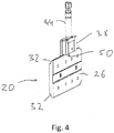
- the quick-change coupling 16 comprises a first coupling unit 18 to be fixed to the plate-like carrier unit 12, for example by screwing, and a second coupling unit 20 to be fixed to the device carrier 14, for example by screwing. This can be fixed to a carrier plate 22 provided on the device carrier 14.
- the quick-change coupling 16 offers the possibility of attaching the device carrier 14 to the carrier unit 12 quickly and detachably by coupling the two coupling units 18, 20 thereof.
- a sliding engagement recess 24 is provided on the first coupling unit 18.
- the second coupling unit 20 comprises or is formed with a sliding engagement body 26, with its plate-like structure in the sliding engagement recess 24th can be inserted.
- the sliding engagement recess in their running in a sliding direction R side edge regions, for example, a dovetail inner profile 30 formed undercut 28.
- the sliding engagement body 26 as the undercut 28 engaging body, for example, constructed with dovetail outer profile 32.
- the sliding engagement body 26 of the second coupling unit 20 fixed to the device carrier 14 is pushed into the sliding engagement recess 24 substantially in the horizontal direction in the sliding direction R, for example.
- the sliding engagement recess 24 is preferably limited by a slide-in stop 34 in the sliding direction R, so that by the insertion stopper 34, a maximum insertion position of the sliding engagement body 26 can be set in the sliding engagement recess 24. Moving beyond this maximum insertion position is not possible.
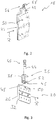
- a clamping positioning arrangement 36 is provided on the first coupling unit 18.
- This comprises a clamping positioning element 38 which is displaceable on the first coupling unit 18 essentially transversely to the sliding direction R and an actuator 40 assigned to the clamping positioning element 38.
- the actuator 40 is in turn preferably provided with a housing 42 provided, for example, in a housing 42
- Adjusting spindle 44 is provided, which is preferably self-locking and whose operation leads to a displacement of the clamping positioning member transverse to the sliding direction R.
- the clamp positioning member 38 With sliding engagement body 26 inserted into the sliding engagement recess 24, by moving the clamp positioning member 38 toward the sliding engagement body 26, the clamp positioning member 38 can be moved laterally Edge region of the sliding engagement body 26 are brought into abutment and pressed against it with pressure.
- the contour of the clamping positioning member 38 of the contour of the sliding engagement recess 24 may be adapted to provide the undercut, so the dovetail inner profile 30, so that the clamp positioning member 38, the complementarily shaped and formed with dovetail outer profile 32 edge region of the slide Engaging body 26 can overlap.
- a form-fitting positioning arrangement generally designated 46, is also provided.
- This comprises a pin-like positive locking positioning member 48, which may be provided for example on the terminal positioning member 38 or provided by this.
- a form-fitting positioning recess 50 is provided on the sliding engagement body 26 such that it is open substantially orthogonal to the sliding direction R.
- the form-locking positioning member 48 and the form-fitting positioning recess 50 are matched to one another in such a way that, when the form-locking positioning member 48 engages in the form-fitting positioning recess 50, there is essentially no movement play between the sliding engagement member 26 and the positive-locking positioning member 38 and thus substantially the positive locking positioning member 38 receiving first coupling unit 18 is present.
- the clamping positioning arrangement 36 and thus also the form-locking positioning arrangement 46 are in a release state.
- the sliding engagement body 26 can be freely inserted until it comes to the insertion stop 34 in abutment.
- the clamping positioning member 38 and with this the positive locking positioning member 48 in the direction of the sliding engagement body 26 moves.
- the positive locking positioning member 48 enters the positive locking positioning recess 50 a.
- a Positionierschräge 52 is provided in the example shown on the positive locking positioning member 48.
- a force opposing the sliding direction R is applied to the sliding engagement body 26 , whereby the sliding engagement body 26 is displaced in the direction of the operating position.
- the positive lock positioning member 48 and the positive lock positioning recess 50 are correctly aligned with each other, and the positive lock positioning member 48 can further enter the positive lock positioning recess 50 for defining the slide engagement body 26 so that a positive lock positioning state is reached, in which a movement of the Sliding engagement body 26 in the sliding direction R or opposite to the sliding direction R is no longer possible.
- this may additionally be associated with a generally designated 56 blocking arrangement.
- This can, for example, housed in the housing 42, an activatable by a clamping lever 58 clamping element which presses in the guided in the housing 42 area of the actuator 40 and the adjusting spindle 44 against this and thus by Reibkraft gleich and / or by positive locking a loosening of already self-locking actuator 40 prevents.
- the blocking arrangement 56 can first be deactivated. Then, by acting on the adjusting spindle 44, the clamping positioning assembly 36 and with this the form-locking positioning assembly 46 by laterally pulling out of the clamping Positionierorgans 38 and the positive locking Positionierorgans 48 brought into the release state in which the sliding engagement body 26 together with can be moved laterally out of the sliding engagement recess 24 to carry this carrying device carrier 14, for example, to bring another, already equipped with components to be welded device carrier with the sliding engagement body carried on it into engagement with the first coupling unit 18 for a subsequent welding operation.
- the plate-like slide engagement body 26 providing substantially the second clutch unit 20 may be made of a single plate-like member preferably constructed of metal material.
- the more complexly designed second coupling unit 18 may be constructed with a base plate to be fixed to the support unit 12 and also providing the bottom 54 of the sliding engagement recess 24, preferably of metal material, on which the dovetail inner profile 30 provides side plates and an end plate providing the insertion stop 34, preferably each constructed of metal material, for example, can be determined by screwing.
- the adjusting spindle 44 and the blocking assembly 56 accommodating housing 42 may be housed.
- This side plate further has a recess in which the transversely to the sliding direction R displaceable clamping positioning member 38 is received or guided.
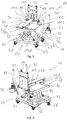
- FIGS. 5 and 6 show a generally designated 60 transport system, which on the one hand the foregoing with reference to the Fig. 1 already explained device carrier 14 and on the other hand in the transport or storage state, the device carrier 14 receiving trolley 62 includes.
- the device carrier 14 equipped with components to be welded can be produced using the above with reference to FIGS Fig. 1 to 4 described in detail in a welding cell 11 of a welding system 10 are described or removed from this welding cell.
- the transport carriage 62 comprises a lower carriage 64 which is movable on, for example, four rollers 68 provided on a frame 66. It should be noted that for the purposes of the present invention, a roll any suitable for moving the trolley 62 formation such. As roller, wheel or the like.
- the frame 66 of the undercarriage 64 is constructed with two elongated and mutually firmly connected hollow profile parts 69, 70. These form respective engagement wells 72, 74 of a lifting machine engagement formation, generally designated 76.
- a lifting machine such as a forklift or a lift truck or the like, can be positioned engaging with corresponding fork-shaped lifting tines in the engaging wells 72, 74 and so lift the entire trolley 62 and the entire transport system 60 and position, for example, in a storage rack or the like or from remove such a bearing positioning.
- a superstructure On the undercarriage 64, a superstructure, generally designated 78, is adjustably carried in the vertical direction.
- the uppercarriage 78 comprises a plate-like support 80, which is adjustable by means of a scissor lift mechanism 82 in the height direction.
- the scissor lift 82 is associated with an actuator 84.
- this comprises a piston / cylinder unit 86 which is to be actuated with pressurized fluid, in particular hydraulically, in order to adjust the superstructure 78 in the vertical direction to the undercarriage 64.
- two handles 88, 90 are provided, which allow an operator to move the entire transport system 60 in an ergonomically advantageous attitude.
- a generally designated 92 connection / actuation unit is provided on the handle 88.
- the actuator 84 to an external power source, so a pressurized fluid supply system, and connected with the pressure fluid supply system, the piston / cylinder unit 86 can be adjusted by supply or discharge of pressurized fluid, in this way, the height position of the plate-like support Adjust 80 of the superstructure 78 in the desired manner.
- a positioning / holding formation For fixing the device carrier 14 on the superstructure 78, a positioning / holding formation, generally designated 94, is provided. This ensures that the device carrier 14 can be kept stable and in a defined position on the superstructure 78, but also allows detachment of the device carrier 14 from the superstructure 78, for example, when the two coupling units 18, 20 of the quick-change coupling 16 engaged with each other and thus the device carrier 14 with the components carried thereon is held stably on the carrier unit 12 of a welding cell and for carrying out a welding operation the transporting carriage 62 is to be removed.
- the positioning / holding formation 94 comprises two first positioning / holding units 96, 98.
- the device carrier 14 is held on the superstructure 78 of the trolley 62 in such a way that it is in each spatial direction is essentially immovable. That is, by the holding action of the first positioning / holding units 96, 98, the device carrier 14 can not be moved in the vertical direction up or down, nor in the horizontal direction.
- the first positioning / holding unit 96, 98 shown in greater detail on the first positioning / holding unit 98 comprises a substantially U-shaped positioning / holding receptacle 100 on the uppercarriage 78.
- the device carrier 14 or the carrier plate 22 of the same are in association with the two positioning / holding units 96, 98 and the positioning / holding receptacles 100 of the same respective counter-positioning / holding units 104, 106 of a second counter-positioning / Holding formation 103 is provided.
- These include on the support plate 22 laterally projecting positioning / retaining projections 108, 110 which for establishing the holding interaction by lowering the device carrier 14 on the superstructure 78 from above into the receiving recesses 102 of the first positioning / holding units 96, 98 and the positioning / holding receptacles 100 can be introduced and then incorporated therein essentially without movement play.
- the latter When the device carrier 14 is completely lowered, the latter is for example in the region of the carrier plate 22 in the vertical direction on the plate-like carrier 80 of the superstructure 78 and is therefore already held in the vertical direction downwards and in each horizontal direction substantially against movement with respect to the superstructure 78.
- a holding member 112 is provided in association with each first positioning / holding unit 96, 98 or in this recorded first counter-positioning / holding unit 104, 106.
- Each holding member 112 comprises a holding bolt 114, which passes through an opening 116 formed in a respective positioning / holding projection 108, 110 and corresponding openings 118, 120 in the positioning / holding receptacle 100 embracing the positioning / holding projection 108, 110.
- a respective positioning member 112 is assigned a locking unit, generally designated 122.
- a counter-engagement formation 126 providing an undercut is provided on a respective positioning / holding receptacle 100.
- the engagement formation 124 can be brought into and out of engagement with the counter-engagement formation 126, so that at in Fig. 9 Pictured manufactured engagement a respective retaining member 112 can not be moved in the direction of the longitudinal axis L of the retaining bolt 114 and dissolved Engagement of the retaining pin 114 can be removed from these receiving openings 116, 118, 120 or inserted into this.
- the device carrier 114 comprises not only the one hand, the first counter-positioning / holding units 104, 106 and on the other hand, the second coupling unit 20 receiving support plate 22 fixed to the support plate 22 and extending away from this, for example, beam-like support 130.
- the components to be welded together can be positioned using appropriate holding or clamping tools.
- the positioning / holding formation 94 comprises a second positioning / holding unit 134 provided by a support surface 132 on the plate-like carrier 80 of the superstructure 78
- an example rail-type semi-trailer 136 is provided, which provides a second counter-positioning / holding unit 138 substantially.
Landscapes
- Physics & Mathematics (AREA)
- Optics & Photonics (AREA)
- Engineering & Computer Science (AREA)
- Mechanical Engineering (AREA)
- Automatic Assembly (AREA)
Abstract
Ein Transportsystem für den Transport von Vorrichtungen zur Aufnahme von miteinander zu verschweißenden Komponenten, insbesondere für Brennkraftmaschinenabgasanlagen, in eine und aus einer Schweißzelle, umfasst einen Transportwagen (62) mit einem vermittels Rollen (68) auf einem Untergrund verfahrbaren Unterwagen (64) und einem am Unterwagen (64) höhenverstellbar getragenen Oberwagen (78) und wenigstens einen Vorrichtungsträger (14) zur Aufnahme von miteinander zu verschweißenden Komponenten in einer für die Verschweißung vorgesehenen Positionierung bezüglich einander, wobei am Oberwagen (78) eine Positionier/Halte-Formation (94) vorgesehen ist und am Vorrichtungsträger (14) eine zum Vorgeben einer Transportpositionierung des Vorrichtungsträgers (14) auf dem Oberwagen (78) mit der Positionier/HalteFormation (94) in Eingriff stehende oder bringbare Gegen-Positionier/HalteFormation (103) vorgesehen ist.A transport system for the transport of devices for receiving components to be welded together, in particular for engine exhaust systems, in and out of a welding cell comprises a trolley (62) with a means of rollers (68) movable on a substrate undercarriage (64) and an am Undercarriage (64) height adjustable supported uppercarriage (78) and at least one device carrier (14) for receiving components to be welded together in a position provided for the welding positioning relative to each other, wherein the upper carriage (78) a positioning / holding formation (94) provided and on the device carrier (14) for setting a transport positioning of the device carrier (14) on the superstructure (78) with the positioning / HalteFormation (94) in engagement or engageable counter-positioning / HalteFormation (103) is provided.
Description
Die vorliegende Erfindung betrifft ein Transportsystem für den Transport von Vorrichtungen zur Aufnahme von miteinander zu verschweißenden Komponenten z.B. für Brennkraftmaschinenabgasanlagen in eine und aus einer Schweißzelle.The present invention relates to a transport system for the transport of devices for receiving components to be welded together, e.g. for engine exhaust systems in and out of a welding cell.
Für die Durchführung von Schweißvorgängen ist es von Bedeutung, dass derartige Vorrichtungen zur Aufnahme der miteinander zu verschweißenden Komponenten schnell und mit großer Präzision in eine Schweißzelle einer Schweißanlage eingebracht und daraus wieder entfernt werden können.For carrying out welding operations, it is important that such devices for receiving the components to be welded together can be quickly and with great precision introduced into a welding cell of a welding system and removed therefrom.
Es ist daher eine Aufgabe der vorliegenden Erfindung, ein Transportsystem vorzusehen, welches eine schnelle und präzise Positionierung von Vorrichtungen zur Aufnahme von miteinander zu verschweißenden Komponenten, insbesondere für Brennkraftmaschinenabgasanlagen, in einer Schweißzelle auch bei vergleichsweise großem Gewicht des zu bewegenden bzw. positionierenden Systembereichs ermöglicht.It is therefore an object of the present invention to provide a transport system which allows a quick and precise positioning of devices for receiving components to be welded together, in particular for engine exhaust systems, in a welding cell even with a comparatively large weight of the system area to be moved or positioned.
Erfindungsgemäß wird diese Aufgabe gelöst durch ein Transportsystem für den Transport von Vorrichtungen zur Aufnahme von miteinander zu verschweißenden Komponenten, insbesondere für Brennkraftmaschinenabgasanlagen, in eine und aus einer Schweißzelle, umfassend:
- einen Transportwagen mit einem vermittels Rollen auf einem Untergrund verfahrbaren Unterwagen und einem am Unterwagen höhenverstellbar getragenen Oberwagen,
- wenigstens einen Vorrichtungsträger zur Aufnahme von miteinander zu verschweißenden Komponenten in einer für die Verschweißung vorgesehenen Positionierung bezüglich einander,
- a trolley with a means of rolling on a substrate movable undercarriage and a height-adjustable supported on the undercarriage uppercarriage,
- at least one device carrier for receiving components to be welded together in a position provided for welding relative to each other,
Durch die Zusammenwirkung von Transportwagen und Vorrichtungsträger wird eine zuverlässige Handhabung und Positionierung auch großer Gewichte ermöglicht.The interaction of the trolley and the device carrier enables reliable handling and positioning of even large weights.
Eine definierte Relativpositionierung zwischen Transportwagen und Vorrichtungsträger kann dadurch gewährleistet werden, dass die Positionier/HalteFormation wenigstens eine, vorzugsweise wenigstens zwei erste Positionier/Halte-Einheiten und die Gegen-Positionier/Halte-Formation wenigstens eine, vorzugsweise wenigstens zwei jeweils mit einer ersten Positionier/Halte-Einheit in Eingriff stehende oder bringbare erste Gegen-Positionier/Halte-Einheiten umfasst, wobei durch jede mit einer ersten Positionier/Halte-Einheit in Eingriff stehenden ersten Gegen-Positionier/Halte-Einheit der Vorrichtungsträger bezüglich des Oberwagens in jeder Raumrichtung im Wesentlichen unbewegbar gehalten ist.A defined relative positioning between transport carriage and device carrier can be ensured by the positioning / holding formation at least one, preferably at least two first positioning / holding units and the counter positioning / holding formation at least one, preferably at least two each with a first positioning / Holding unit comprises engageable or engageable first counter-positioning / holding units, wherein by each engaging with a first positioning / holding unit first counter-positioning / holding unit of the device carrier with respect to the upper carriage in each spatial direction substantially is held immovable.
Dabei kann wenigstens eine, vorzugsweise jede erste Positionier/Halte-Einheit oder wenigstens eine, vorzugsweise jede erste Gegen-Positionier/Halte-Einheit eine Positionier/Halte-Aufnahme aufweisen, und wenigstens eine, vorzugsweise jede erste Gegen-Positionier/Halte-Einheit oder wenigstens eine, vorzugsweise jede erste Positionier/Halte-Einheit kann einen in eine Positionier/Halte-Aufnahme eingreifend positionierten oder positionierbaren Positionier/Halte-Vorsprung umfassen.In this case, at least one, preferably each first positioning / holding unit or at least one, preferably each first counter-positioning / holding unit having a positioning / holding receptacle, and at least one, preferably each first counter-positioning / holding unit or At least one, preferably each first positioning / holding unit may comprise a positioning / retaining projection that is positioned or positionable in a positioning / holding receptacle.
Für einen stabilen Zusammenhalt kann vorgesehen sein, dass jede erste Positionier/Halte-Einheit oder/und erste Gegen-Positionier/Halte-Einheit in Zuordnung zu wenigstens dem in eine Positionier/Halte-Aufnahme eingreifend positionierten oder positionierbaren Positionier/Halte-Vorsprung ein ein Herausbewegen des Positionier/Halte-Vorsprungs aus der diesen aufnehmenden Positionier/Halte-Aufnahme verhinderndes Halteorgan umfasst. Beispielsweise kann dabei wenigstens ein, vorzugsweise jedes Halteorgan einen wenigstens eine Öffnung einer Positionier/Halte-Aufnahme und eine damit ausgerichtete Öffnung eines in die Positionier/Halte-Aufnahme eingreifend positionierten oder positionierbaren Positionier/Halte-Vorsprungs durchsetzend positionierten oder positionierbaren Haltebolzen umfassen.For a stable cohesion can be provided that each first positioning / holding unit and / or first counter-positioning / holding unit in association with at least one of the positioning / holding receptacle engaging positioned or positionable positioning / holding projection a Moving out of the positioning / holding projection from the retaining this positioning receiving / holding receptacle preventing. For example, at least one, preferably each, holding member may comprise an at least one opening of a positioning / holding receptacle and an opening of a positioning bolt / holding projection, which is positioned or positionable in the positioning / holding receptacle and positioned or positionable.
Um ein Loslösen eines derartigen Halteorgans zu vermeiden, wird weiter vorgeschlagen, wenigstens einem, vorzugsweise jedem Halteorgan eine dieses gegen Herausbewegen aus den Öffnungen sichernde, vorzugsweise formschlüssig wirkende und durch Drehen des Halteorgans aktivierbare und deaktivierbare, Arretieranordnung zugeordnet ist.In order to avoid detachment of such a holding member, it is further proposed, at least one, preferably each holding member associated with this one against moving out of the openings securing, preferably positively acting and activatable by turning the retainer and deactivatable, locking assembly is assigned.
Ein definierte Relativpositionierung zwischen Transportwagen und Vorrichtungsträger kann weiter dadurch unterstützt werden, dass die Positionier/Halte-Formation wenigstens eine zweite Positionier/Halte-Einheit umfasst, und dass die Gegen-Positionier/Halte-Formation wenigstens eine mit einer zweiten Positionier/HalteEinheit in Eingriff stehende oder bringbare zweite Gegen-Positionier/Halte-Einheit umfasst, wobei durch jede mit einer zweiten Positionier/Halte-Einheit in Eingriff stehende zweite Gegen-Positionier/Halte-Einheit der Vorrichtungsträger bezüglich des Oberwagens gegen Bewegung im Wesentlichen in horizontaler Richtung oder/und gegen die Bewegung in vertikaler Richtung nach unten gehalten ist.A defined relative positioning between the transport carriage and the device carrier can be further assisted in that the positioning / holding formation comprises at least one second positioning / holding unit, and in that the counter positioning / holding formation engages at least one with a second positioning / holding unit standing or bringable second counter-positioning / holding unit, wherein by each engaging with a second positioning / holding unit second counter-positioning / holding unit, the device carrier relative to the upper carriage against movement substantially in the horizontal direction and / or held down against the movement in a vertical direction.
Hierzu kann beispielsweise wenigstens eine, vorzugsweise jede zweite Positionier/Halte-Einheit eine Auflagefläche am Oberwagen umfassen, und wenigstens eine, vorzugsweise jede zweite Gegen-Positionier/Halte-Einheit kann einen auf einer Auflagefläche am Oberwagen aufliegend positionierten oder positionierbaren Auflieger umfassen.For this purpose, for example, at least one, preferably every second positioning / holding unit comprise a bearing surface on the upper carriage, and at least one, preferably every second counter-positioning / holding unit may comprise a resting on a support surface on the superstructure positioned or positionable semi-trailer.
Zum Bewegen eines Vorrichtungsträgers in die gewünschte Position kann am Transportwagen, vorzugsweise am Unterwagen, wenigstens ein Handgriff zum Bewegen des Transportwagens vorgesehen sein. Ferner kann der Oberwagen bezüglich des Unterwagens durch einen Scherenhubmechanismus höhenverstellbar getragen sein, oder/und am Transportwagen, vorzugsweise am Unterwagen, kann eine Hubmaschinen-Eingriffsformation vorgesehen sein.For moving a device carrier in the desired position can be provided on the trolley, preferably on the undercarriage, at least one handle for moving the trolley. Furthermore, the upper carriage with respect to the undercarriage can be supported by a Scherenhubmechanismus height adjustable, and / or on the trolley, preferably on the undercarriage, a lifting machine engagement formation can be provided.
Für die Zusammenwirkung mit einer derartigen z.B. als Gabelstapler oder Hubwagen ausgebildeten Hubmaschine kann die Hubmaschinen-Eingriffsformation wenigstens zwei Hubwerkzeug-Eingriffsöffnungen, vorzugsweise zueinander im Wesentlichen parallel sich erstreckende Eingriffsschächte, umfassen.For interaction with such a lifting machine designed, for example, as a forklift or lift truck, the lifting machine engagement formation may comprise at least two lifting tool engagement openings, preferably engaging shafts extending substantially parallel to one another.
Um auch bei vergleichsweise großen zu bewegenden Lasten eine präzise Verstellung des Oberwagens bezüglich des Unterwagens zu ermöglichen, wird vorgeschlagen, dass dem Scherenhubmechanismus ein mit Druckfluid, vorzugsweise hydraulisch, betätigter Stellantrieb zugeordnet ist, oder/und dass am Transportwagen, vorzugsweise am Unterwagen, eine Anschluss/Betätigungs-Einheit zum Anschluss eines dem Scherenhubmechanismus zugeordneten Stellantriebs an eine Energiequelle und zur Betätigung des Stellantriebs vorgesehen ist.In order to enable a precise adjustment of the superstructure with respect to the undercarriage even with comparatively large loads to be moved, it is proposed that the scissor lift mechanism is associated with a pressure fluid, preferably hydraulically actuated actuator, and / or that on the trolley, preferably on the undercarriage, a connection / Actuating unit is provided for connecting an associated with the Scherenhubmechanismus actuator to a power source and for actuating the actuator.
Um einen vermittels des Transportwagens in eine Schweißzelle transportierten Vorrichtungsträger in der Schweißzelle zur Durchführung eines Schweißvorgangs zu halten, wird vorgeschlagen, dass an wenigstens einem, vorzugsweise jedem Vorrichtungsträger eine zum lösbaren Festlegen des Vorrichtungsträgers an einer an einer Schweißzelle vorgesehenen ersten Kupplungseinheit mit der ersten Kupplungseinheit in Eingriff bringbare zweite Kupplungseinheit vorgesehen ist.In order to keep a device carrier transported by means of the transport carriage into a welding cell in the welding cell for carrying out a welding operation, it is proposed that at least one, preferably each device carrier, one for detachably fixing the device carrier to a first coupling unit provided on a welding cell with the first coupling unit Engagement engageable second coupling unit is provided.
Dabei kann eine Kupplungseinheit von erster Kupplungseinheit und zweiter Kupplungseinheit eine Schiebe-Eingriffsaussparung aufweisen, und die andere Kupplungseinheit von erster Kupplungseinheit und zweiter Kupplungseinheit kann einen in einer Schieberichtung in die Schiebe-Eingriffsaussparung einschiebbaren Schiebe-Eingriffskörper aufweisen.Here, one coupling unit of the first coupling unit and the second coupling unit may have a sliding engagement recess, and the other coupling unit of the first coupling unit and the second coupling unit may have a sliding engagement body insertable into the sliding engagement recess in a sliding direction.
Zum Sichern einer stabilen Position auch während eines Schweißvorgangs kann eine zwischen einem Freigabezustand und einem Formschluss-Positionierzustand verstellbare Formschluss-Positionieranordnung vorgesehen sein, wobei bei in die Schiebe-Eingriffsaussparung eingreifend positioniertem Schiebe-Eingriffskörper die Formschluss-Positionieranordnung im Formschluss-Positionierzustand den Schiebe-Eingriffskörper in einer Betriebsstellung bezüglich der Schiebe-Eingriffsaussparung positioniert gegen Verschiebung in der Schiebe-Eingriffsaussparung hält.In order to secure a stable position even during a welding operation, a positive locking positioning assembly adjustable between a release state and a positive locking positioning state may be provided, with the sliding engagement body engaged with the sliding engagement recess, the positive locking positioning assembly in the positive locking positioning state, the sliding engagement body positioned against displacement in the slide engagement recess in an operative position with respect to the slide engagement recess.
Die Schiebe-Eingriffsaussparung kann eine Hinterschneidung bilden, und der in die Schiebe-Eingriffsaussparung eingeschobene Schiebe-Eingriffskörper kann die Hinterschneidung hintergreifen, wobei vorzugsweise die Schiebe-Eingriffsaussparung ein Schwalbenschwanz-Innenprofil aufweist und der Schiebe-Eingriffskörper ein Schwalbenschwanz-Außenprofil aufweist.The slide engagement recess may form an undercut, and the slide engagement body inserted into the slide engagement recess may engage behind the undercut, preferably with the slide engagement recess has a dovetail inner profile and the sliding engagement body has a dovetail outer profile.
Die vorliegende Erfindung wird nachfolgend mit Bezug auf die beiliegenden Figuren detailliert beschrieben. Es zeigt:
- Fig. 1
- die wesentlichen Systembereiche einer Schweißanlage zum Verschweißen von Komponenten für Brennkraftmaschinenabgasanlagen;
- Fig. 2
- in perspektivischer Ansicht eine an einer Trägereinheit einer Schweißzelle festzulegende erste Kupplungseinheit einer Schnellwechselkupplung;
- Fig. 3
- in perspektivischer Ansicht eine an einem Vorrichtungsträger festzulegenden zweiten Kupplungseinheit der Schnellwechselkupplung mit einer zugeordnete Klemm-Positionieranordnung;
- Fig. 4
- eine der
Fig. 3 entsprechende Ansicht der zweiten Kupplungseinheit mit der daran angreifenden Klemm-Positionieranordnung. - Fig. 5
- in perspektivischer Darstellung ein Transportsystem mit einem Transportwagen und einem auf einem Oberwagen des Transportwagens getragenen Vorrichtungsträger;
- Fig. 6
- eine andere perspektivische Ansicht des Transportsystems der
Fig. 5 ; - Fig. 7
- den Transportwagen des Transportsystems der
Fig. 5 in perspektivischer Ansicht; - Fig. 8
- den in
Fig. 7 dargestellten Transportwagen, betrachtet in anderer Richtung; - Fig. 9
- eine mit einer Gegen-Positionier/Halte-Einheit zusammen wirkende Positionier/Halte-E inheit.
- Fig. 1
- the essential system areas of a welding system for welding components for internal combustion engine exhaust systems;
- Fig. 2
- in a perspective view to be determined on a support unit of a welding cell first coupling unit of a quick-change coupling;
- Fig. 3
- in perspective view to be determined on a device carrier second coupling unit of the quick-change coupling with an associated clamping positioning;
- Fig. 4
- one of the
Fig. 3 corresponding view of the second coupling unit with the attacking clamping positioning. - Fig. 5
- a perspective view of a transport system with a trolley and carried on a superstructure of the trolley device carrier;
- Fig. 6
- another perspective view of the transport system of
Fig. 5 ; - Fig. 7
- the transport vehicle of the transport system of
Fig. 5 in perspective view; - Fig. 8
- the in
Fig. 7 illustrated dolly, viewed in another direction; - Fig. 9
- a cooperating with a counter-positioning / holding unit positioning / holding E unit.
In
Vermittels einer allgemein mit 16 bezeichneten Schnellwechselkupplung kann der Vorrichtungsträger 14 an der plattenartigen Trägereinheit 12 festgelegt werden, so dass die an dem Vorrichtungsträger 14 getragenen, zu verschweißenden Komponenten in der Schweißzelle 11 in geeigneter Positionierung gehalten bzw. angeordnet werden können.By means of a quick-change coupling designated generally by 16, the
Die Schnellwechselkupplung 16 umfasst eine an der plattenartigen Trägereinheit 12 beispielsweise durch Verschraubung festzulegende erste Kupplungseinheit 18 und eine an dem Vorrichtungsträger 14 beispielsweise ebenfalls durch Verschraubung festzulegende zweite Kupplungseinheit 20. Diese kann an einer am Vorrichtungsträger 14 vorgesehenen Trägerplatte 22 festgelegt werden.The quick-
Die Schnellwechselkupplung 16 bietet die Möglichkeit, durch Koppeln der beiden Kupplungseinheiten 18, 20 derselben den Vorrichtungsträger 14 schnell und lösbar an der Trägereinheit 12 anzubringen. Um dies zu ermöglichen, ist an der ersten Kupplungseinheit 18 eine Schiebe-Eingriffsaussparung 24 vorgesehen. Die zweite Kupplungseinheit 20 umfasst bzw. ist ausgebildet mit einem Schiebe-Eingriffskörper 26, der mit seiner plattenartigen Struktur in die Schiebe-Eingriffsaussparung 24 eingeschoben werden kann. Um durch das Einschieben einen festen, formschlüssigen Eingriff zu erzeugen, bildet die Schiebe-Eingriffsaussparung in ihren in einer Schieberichtung R verlaufenden Seitenrandbereichen eine beispielsweise nach Form eines Schwalbenschwanz-Innenprofils 30 ausgebildete Hinterschneidung 28. In entsprechender Weise ist der Schiebe-Eingriffskörper 26 als die Hinterschneidung 28 hintergreifender Körper, beispielsweise mit Schwalbenschwanz-Außenprofil 32 aufgebaut.The quick-
Zum Herstellen des Schiebeeingriffs wird der am Vorrichtungsträger 14 festgelegte Schiebe-Eingriffskörper 26 der zweiten Kupplungseinheit 20 beispielsweise im Wesentlichen in horizontaler Richtung in der Schieberichtung R in die Schiebe-Eingriffsaussparung 24 eingeschoben. Die Schiebe-Eingriffsaussparung 24 ist vorzugsweise durch einen Einschubanschlag 34 in der Schieberichtung R begrenzt, so dass durch den Einschubanschlag 34 eine maximale Einschiebeposition des Schiebe-Eingriffskörpers 26 in die Schiebe-Eingriffsaussparung 24 vorgegeben werden kann. Eine Bewegung über diese maximale Einschiebeposition hinaus ist nicht möglich.To produce the sliding engagement, the sliding
Um ein Herausbewegen des Schiebe-Eingriffskörpers 26 der zweiten Kupplungseinheit 20 aus der Schiebe-Eingriffsaussparung zu unterbinden, ist an der ersten Kupplungseinheit 18 eine Klemm-Positionieranordnung 36 vorgesehen. Diese umfasst ein an der ersten Kupplungseinheit 18 im Wesentlichen quer zur Schieberichtung R verschiebbares Klemm-Positionierorgan 38 und einen dem Klemm-Positionierorgan 38 zugeordneten Stellantrieb 40. Der Stellantrieb 40 wiederum ist vorzugsweise mit einer beispielsweise in einem an der ersten Kupplungseinheit 18 vorgesehenen Gehäuse 42 aufgenommenen Stellspindel 44 bereitgestellt, die vorzugsweise selbsthemmend ausgebildet ist und deren Betätigung zu einer Verschiebung des Klemm-Positionierorgans quer zur Schieberichtung R führt.In order to prevent the sliding
Bei in die Schiebe-Eingriffsaussparung 24 eingeführtem Schiebe-Eingriffskörper 26 kann durch Bewegen des Klemm-Positionierorgans 38 in Richtung auf den Schiebe-Eingriffskörper 26 zu das Klemm-Positionierorgan 38 an einem seitlichen Randbereich des Schiebe-Eingriffskörpers 26 in Anlage gebracht werden und mit Druck gegen dieses gepresst werden. Dabei kann die Kontur des Klemm-Positionierorgans 38 der Kontur der Schiebe-Eingriffsaussparung 24 zum Bereitstellen der Hinterschneidung, also des Schwalbenschwanz-Innenprofils 30 angepasst sein, so dass das Klemm-Positionierorgan 38 den komplementär geformten und mit Schwalbenschwanz-Außenprofil 32 geformten Randbereich des Schiebe-Eingriffskörpers 26 übergreifen kann.With sliding
Durch das Klemm-Positionierorgan 38 bzw. die Klemm-Positionieranordnung 36 wird bei in die Schiebe-Eingriffsaussparung 24 eingreifend positioniertem und beispielsweise am Einschubanschlag 34 anliegendem Schiebe-Eingriffskörper 26 eine auch ein geringfügiges Bewegungsspiel zwischen diesem und der ersten Kupplungseinheit 18 aufhebende Klemmwirkung erzeugt.By means of the clamping
Um insbesondere in der Schieberichtung R eine definierte Positionierung des Schiebe-Eingriffskörpers 26 bei Erzeugung der Klemmwirkung und damit Festlegung des Schiebe-Eingriffskörpers 26 bezüglich der Schiebe-Eingriffsaussparung 24 erreichen zu können, ist ferner eine allgemein mit 46 bezeichnete Formschluss-Positionieranordnung vorgesehen. Diese umfasst ein zapfenartiges Formschluss-Positionierorgan 48, das beispielsweise am Klemm-Positionierorgan 38 vorgesehen oder durch dieses bereitgestellt sein kann. In Zuordnung zu dem Formschluss-Positionierorgan 48 ist am Schiebe-Eingriffskörper 26 eine Formschluss-Positionieraussparung 50 derart vorgesehen, dass diese im Wesentlichen orthogonal zur Schieberichtung R offen ist. Das Formschluss-Positionierorgan 48 und die Formschluss-Positionieraussparung 50 sind derart aufeinander abgestimmt, dass bei in die Formschluss-Positionieraussparung 50 eingreifendem Formschluss-Positionierorgan 48 im Wesentlichen kein Bewegungsspiel zwischen dem Schiebe-Eingriffskörper 26 und dem Formschluss-Positionierorgan 38 und somit im Wesentlichen auch der das Formschluss-Positionierorgan 38 aufnehmenden ersten Kupplungseinheit 18 vorhanden ist.In order to achieve a defined positioning of the sliding
Um bei der Festlegung des Schiebe-Eingriffskörpers 26 in der Schiebe-Eingriffsaussparung 24 eine Überbestimmung der Positionsvorgabe durch den Einschubanschlag 34 einerseits und das Formschluss-Positionierorgan 48 andererseits zu vermeiden, entspricht die bei Wirksamwerden des Einschubanschlags 34 erreichte maximale Einschiebeposition nicht der für einen Schweißvorgang vorzusehenden Betriebsstellung des Schiebe-Eingriffskörpers 26 in der Schiebe-Eingriffsaussparung 24. Vielmehr ist die maximale Einschiebeposition eine Position, in welche der Schiebe-Eingriffsköper 26 durch Bewegen über die Betriebsposition hinaus gebracht wird.In order to determine the sliding
Zum Einschieben der zweiten Kupplungseinheit 20, also des plattenartigen Schiebe-Eingriffskörpers 26, in die erste Kupplungseinheit 18, also die Schiebe-Eingriffsaussparung 24, ist zunächst die Klemm-Positionieranordnung 36 und damit auch die Formschluss-Positionieranordnung 46 in einem Freigabezustand. In diesem Zustand kann der Schiebe-Eingriffskörper 26 ungehindert eingeschoben werden, bis er am Einschubanschlag 34 in Anlage kommt. Darauffolgend wird durch manuelle oder beispielsweise auch motorische Einwirkung auf den Stellantrieb 40, also insbesondere die Stellspindel 44, das Klemm-Positionierorgan 38 und mit diesem das Formschluss-Positionierorgan 48 in Richtung auf den Schiebe-Eingriffskörper 26 zu bewegt. Noch bevor das Klemm-Positionierorgan 38 seine Klemmwirkung entfalten kann, tritt das Formschluss-Positionierorgan 48 in die Formschluss-Positionieraussparung 50 ein. Da diese nicht in einer der Betriebsstellung entsprechenden Relativpositionierung zueinander sind, ist im dargestellten Beispiel am Formschluss-Positionierorgan 48 eine Positionierschräge 52 vorgesehen. Durch die keilartige Wirkung der Positionierschräge 52 wird bei Bewegung des Formschluss-Positionierorgans 48 auf den Schiebe-Eingriffskörper 26 zu und dabei in die Formschluss-Positionieraussparung 50 eintretendem Formschluss-Positionierorgan 48 auf den Schiebe-Eingriffskörper 26 eine diesen entgegengesetzt zur Schieberichtung R beaufschlagende Kraft entfaltet, wodurch der Schiebe-Eingriffskörper 26 in Richtung zur Betriebsposition verschoben wird. In diesem Zustand sind das Formschluss-Positionierorgan 48 und die Formschluss-Positionieraussparung 50 bezüglich einander korrekt ausgerichtet, und das Formschluss-Positionierorgan 48 kann zur definierten Vorgabe des Schiebe-Eingriffskörpers 26 weiter in die Formschluss-Positionieraussparung 50 eintreten, so dass ein Formschluss-Positionierzustand erreicht ist, in welchem eine Bewegung des Schiebe-Eingriffskörpers 26 in der Schieberichtung R oder entgegengesetzt zur Schieberichtung R nicht mehr möglich ist.For inserting the
Bei weiter fortgesetzter Bewegung des das Formschluss-Positionierorgan 48 auch tragenden Klemm-Positionierorgans 38 in Richtung auf den Schiebe-Eingriffskörper 26 zu kommt das Klemm-Positionierorgan 38 zur Anlage am seitlichen Randberiech des Schiebe-Eingriffskörpers 26 und erzeugt somit in einem dann herbeigeführten Klemm-Positionierzustand eine Klemmwirkung, welche jedwede Bewegung des Schiebe-Eingriffskörpers 26 bezüglich der ersten Kupplungseinheit 18 unterbindet. Dies wird insbesondere dadurch unterstützt, dass durch die seitliche Beaufschlagung des Schiebe-Eingriffskörpers 26 durch das Klemm-Positionierorgan 38 die miteinander in Eingriff stehenden Schwalbenschwanz-Außen- bzw. Innenprofile zusätzlich eine den Schiebe-Eingriffskörper 26 im Wesentlichen senkrecht zur Schieberichtung R in Richtung auf einen Boden 54 der Schiebe-Eingriffsaussparung 24 zu pressende Kraft erzeugt wird.With further continued movement of the positive
Um bei Durchführung eines Schweißvorgangs zu verhindern, dass dabei möglicherweise auftretende Vibrationen zu einem Loslösen des Stellantriebs 40 führen, kann diesem zusätzlich eine allgemein mit 56 bezeichnete Blockieranordnung zugeordnet sein. Diese kann, beispielsweise untergebracht im Gehäuse 42, ein durch einen Klemmhebel 58 aktivierbares Klemmelement umfassen, welches in dem im Gehäuse 42 geführten Bereich des Stellantriebs 40 bzw. der Stellspindel 44 gegen diese presst und somit durch Reibkraftschluss oder/und durch Formschluss ein Lösen des an sich bereits selbsthemmend ausgebildeten Stellantriebs 40 verhindert.In order to prevent any possible vibrations occurring in a detachment of the actuator 40 when performing a welding operation, this may additionally be associated with a generally designated 56 blocking arrangement. This can, for example, housed in the
Soll ein an der Trägereinheit 12 getragener Vorrichtungsträger 14 nach Durchführung eines Schweißvorgangs aus der Schweißzelle einer Schweißanlage 10 entfernt werden, kann zunächst die Blockieranordnung 56 deaktiviert werden. Daraufhin wird durch Einwirken auf die Stellspindel 44 die Klemm-Positionieranordnung 36 und mit dieser die Formschluss-Positionieranordnung 46 durch seitliches Herausziehen des Klemm-Positionierorgans 38 und des Formschluss-Positionierorgans 48 in den Freigabezustand gebracht, in welchem der Schiebe-Eingriffskörper 26 zusammen mit dem diesen tragenden Vorrichtungsträger 14 seitlich aus der Schiebe-Eingriffsaussparung 24 herausbewegt werden kann, um für einen nachfolgend durchzuführenden Schweißvorgang beispielsweise einen anderen, bereits mit zu verschweißenden Komponenten bestückten Vorrichtungsträger mit dem daran getragenen Schiebe-Eingriffskörper in Eingriff mit der ersten Kupplungseinheit 18 zu bringen.If a
Es ist darauf hinzuweisen, dass der im Wesentlichen die zweite Kupplungseinheit 20 bereitstellende, plattenartige Schiebe-Eingriffskörper 26 aus einem einzigen vorzugsweise mit Metallmaterial aufgebauten, plattenartigen Bauteil bestehen kann. Die komplexer gestaltete zweite Kupplungseinheit 18 kann mit einer an der Trägereinheit 12 festzulegenden, und auch den Boden 54 der Schiebe-Eingriffsaussparung 24 bereitstellenden Basisplatte vorzugsweise aus Metallmaterial aufgebaut sein, an welcher das Schwalbenschwanz-Innenprofil 30 bereitstellende Seitenplatten und eine den Einschubanschlag 34 bereitstellende Endplatte, vorzugsweise jeweils aus Metallmaterial aufgebaut, beispielsweise durch Verschraubung festgelegt sein können. Im Bereich einer der Seitenplatten kann das die Stellspindel 44 und die Blockieranordnung 56 aufnehmende Gehäuse 42 untergebracht sein. Diese Seitenplatte weist weiterhin eine Aussparung auf, in welcher das quer zur Schieberichtung R verschiebbare Klemm-Positionierorgan 38 aufgenommen bzw. geführt ist.It should be noted that the plate-like
Die
Der Transportwagen 62 umfasst einen Unterwagen 64, der auf beispielsweise vier an einem Rahmen 66 vorgesehenen Rollen 68 verfahrbar ist. Es sei darauf hingewiesen, dass im Sinne der vorliegenden Erfindung eine Rolle jedwede zum Verfahren des Transportwagens 62 geeignete Formation, wie z. B. Walze, Rad oder dergleichen umfasst. Der Rahmen 66 des Unterwagens 64 ist mit zwei langgestreckten und miteinander fest verbundenen Hohlprofilteilen 69, 70 aufgebaut. Diese bilden jeweilige Eingriffsschächte 72, 74 einer allgemein mit 76 bezeichneten Hubmaschinen-Eingriffsformation. Eine Hubmaschine, beispielsweise ein Gabelstapler oder ein Hubwagen oder dergleichen, kann mit entsprechenden gabelartig geformten Hubzinken in die Eingriffsschächte 72, 74 eingreifend positioniert werden und so den gesamten Transportwagen 62 bzw. das gesamte Transportsystem 60 anheben und beispielsweise in einem Lagerregal oder dergleichen positionieren oder von einer derartigen Lagerpositionierung entnehmen.The
Auf dem Unterwagen 64 ist ein allgemein mit 78 bezeichneter Oberwagen in Höhenrichtung verstellbar getragen. Der Oberwagen 78 umfasst einen plattenartigen Träger 80, der vermittels eines Scherenhubmechanismus 82 in Höhenrichtung verstellbar ist. Dem Scherenhubmechanismus 82 ist ein Stellantrieb 84 zugeordnet. Dieser umfasst im dargestellten Beispiel eine Kolben/Zylinder-Einheit 86, die mit Druckfluid, insbesondere hydraulisch, zu betätigen ist, um den Oberwagen 78 in Höhenrichtung auf den Unterwagen 64 zu verstellen.On the
Am Unterwagen 64 sind zwei Handgriffe 88, 90 vorgesehen, welche es einer Bedienperson ermöglichen, in ergonomisch vorteilhafter Haltung das gesamte Transportsystem 60 zu bewegen. Am Handgriff 88 ist eine allgemein mit 92 bezeichnete Anschluss/Betätigungs-Einheit vorgesehen. Über diese kann der Stellantrieb 84 an eine externe Energiequelle, also ein Druckfluidversorgungssystem, angeschlossen werden und kann bei angeschlossenem Druckfluidversorgungssystem die Kolben/Zylinder-Einheit 86 durch Zuleiten bzw. Ableiten von Druckfluid verstellt werden, um auf diese Art und Weise die Höhenposition des plattenartigen Trägers 80 des Oberwagens 78 in gewünschter Weise einzustellen.On the
Zur Festlegung des Vorrichtungsträgers 14 auf dem Oberwagen 78 ist eine allgemein mit 94 bezeichnete Positionier/Halte-Formation vorgesehen. Diese sorgt dafür, dass der Vorrichtungsträger 14 stabil und in definierter Position auf dem Oberwagen 78 gehalten werden kann, gestattet jedoch auch ein Loslösen des Vorrichtungsträgers 14 vom Oberwagen 78, beispielsweise dann, wenn die beiden Kupplungseinheiten 18, 20 der Schnellwechselkupplung 16 in Eingriff miteinander gebracht sind und somit der Vorrichtungsträger 14 mit den darauf getragenen Komponenten stabil an der Trägereinheit 12 einer Schweißzelle gehalten ist und für die Durchführung eines Schweißvorgangs der Transportwagen 62 zu entfernen ist.For fixing the
Die Positionier/Halte-Formation 94 umfasst zwei erste Positionier/Halte-Einheiten 96, 98. Vermittels der beiden ersten Positionier/Halte-Einheiten 96, 98 ist der Vorrichtungsträger 14 derart an dem Oberwagen 78 des Transportwagens 62 gehalten, dass er in jeder Raumrichtung im Wesentlichen unbewegbar ist. Das heißt, durch die Haltewirkung der ersten Positionier/Halte-Einheiten 96, 98 kann der Vorrichtungsträger 14 weder in vertikaler Richtung nach oben oder unten, noch in Horizontaler Richtung bewegt werden. Jede der in
Am Vorrichtungsträger 14 bzw. der Trägerplatte 22 desselben sind in Zuordnung zu den beiden Positionier/Halte-Einheiten 96, 98 bzw. den Positionier/Halte-Aufnahmen 100 derselben jeweilige Gegen-Positionier/Halte-Einheiten 104, 106 einer zweiten Gegen-Positionier/Halte-Formation 103 vorgesehen. Diese umfassen an der Trägerplatte 22 seitlich vorstehende Positionier/Halte-Vorsprünge 108, 110, welche zur Herstellung der Haltewechselwirkung durch Absenken des Vorrichtungsträgers 14 auf den Oberwagen 78 zu von oben in die Aufnahmeaussparungen 102 der ersten Positionier/Halte-Einheiten 96, 98 bzw. der Positionier/Halte-Aufnahmen 100 derselben eingeführt werden können und dann darin im Wesentlichen ohne Bewegungsspiel aufgenommen sind. Bei vollständig abgesenktem Vorrichtungsträger 14 liegt dieser beispielsweise im Bereich der Trägerplatte 22 dann in vertikaler Richtung auf dem plattenartigen Träger 80 des Oberwagens 78 auf und ist somit bereits in vertikaler Richtung nach unten und in jeder Horizontalrichtung im Wesentlichen gegen Bewegung bezüglich des Oberwagens 78 gehalten.On the
Um einen sicheren Zusammenhalt zu gewährleisten, ist in Zuordnung zu jeder ersten Positionier/Halte-Einheit 96, 98 bzw. in dieser aufgenommenen ersten Gegen-Positionier/Halte-Einheit 104, 106 ein Halteorgan 112 vorgesehen. Jedes Halteorgan 112 umfasst einen Haltebolzen 114, der eine in einem jeweiligen Positionier/HalteVorsprung 108, 110 ausgebildete Öffnung 116 sowie entsprechende Öffnungen 118, 120 in der den Positionier/Halte-Vorsprung 108, 110 umgreifenden Positionier/Halte-Aufnahme 100 durchsetzt. Durch den Haltebolzen 114 wird somit auch in Richtung vertikal nach oben ein Formschluss generiert, welcher ein Abheben des Vorrichtungsträgers 14 vom Oberwagen 78 verhindert.In order to ensure a secure cohesion, a holding
Um ein Loslösen der in die Öffnungen 116, 118, 120 eingreifenden Haltebolzen 114 von den jeweiligen ersten Positionier/Halte-Einheiten 96, 98 zu verhindern, ist einem jeweiligen Positionierorgan 112 eine allgemein mit 122 bezeichnete Arretiereinheit zugeordnet. Diese umfasst an einem jeweiligen Haltebolzen 114 eine bezüglich einer jeweiligen Längsachse L des Haltebolzens 114 nicht rotationssymmetrische, beispielsweise scheibenartige Eingriffsformation 124, die, wie in
Der Vorrichtungsträger 114 umfasst neben der einerseits die ersten Gegen-Positionier/Halte-Einheiten 104, 106 und andererseits die zweite Kupplungseinheit 20 aufnehmenden Trägerplatte 22 einen an der Trägerplatte 22 festgelegten und von dieser sich weg erstreckenden, beispielsweise balkenartigen Träger 130. Auf dem balkenartigen Träger 130 können die miteinander zu verschweißenden Komponenten unter Einsatz entsprechender Halte- bzw. Spannwerkzeuge positioniert werden. An dem von der Anbindung an die Trägerplatte 22 entfernten Endbereich des balkenartigen Trägers 130 umfasst die Positionier/Halte-Formation 94 eine durch eine Auflagefläche 132 auf dem plattenartigen Träger 80 des Oberwagens 78 bereitgestellte zweite Positionier/Halte-Einheit 134. Am balkenartigen Träger 130 des Vorrichtungsträgers 14 ist ein beispielsweise schienenartiger Auflieger 136 vorgesehen, der im Wesentlichen eine zweite Gegen-Positionier/Halte-Einheit 138 bereitstellt. Bei auf dem Oberwagen 78 positioniertem Vorrichtungsträger 14 liegt dieser somit auch in seinem von der Trägerplatte 22 entfernten Endbereich stabil auf dem Oberwagen 78 auf und ist somit durch die Zusammenwirkung der zweiten Positionier/Halte-Einheit 134 mit der zweiten Gegen-Positionier/Halte-Einheit 138 gegen Bewegung in Richtung nach vertikal unten gehalten. Aufgrund der bestehenden Reibwechselwirkung kann auch eine in horizontaler Richtung wirkende Haltewechselwirkung erzielt werden. Um dies zu verstärken, können an der Auflagefläche 132 einerseits und dem Auflieger 136 andererseits jeweilige Vorsprünge bzw. Aussparungen vorgesehen sein, die bei Absenken des Vorrichtungsträgers 14 auf dem Oberwagen 78 zu miteinander in Eingriff gebracht werden und somit einen in Horizontalrichtung wirkenden Formschluss erzeugen können.The
Claims (14)
Priority Applications (1)
| Application Number | Priority Date | Filing Date | Title |
|---|---|---|---|
| PL19154478T PL3524382T3 (en) | 2018-02-05 | 2019-01-30 | Transport system |
Applications Claiming Priority (2)
| Application Number | Priority Date | Filing Date | Title |
|---|---|---|---|
| DE102018102457 | 2018-02-05 | ||
| DE102018104880.7A DE102018104880A1 (en) | 2018-02-05 | 2018-03-05 | transport system |
Publications (2)
| Publication Number | Publication Date |
|---|---|
| EP3524382A1 true EP3524382A1 (en) | 2019-08-14 |
| EP3524382B1 EP3524382B1 (en) | 2020-09-30 |
Family
ID=65268800
Family Applications (1)
| Application Number | Title | Priority Date | Filing Date |
|---|---|---|---|
| EP19154478.2A Active EP3524382B1 (en) | 2018-02-05 | 2019-01-30 | Transport system |
Country Status (2)
| Country | Link |
|---|---|
| EP (1) | EP3524382B1 (en) |
| PL (1) | PL3524382T3 (en) |
Cited By (3)
| Publication number | Priority date | Publication date | Assignee | Title |
|---|---|---|---|---|
| CN112622613A (en) * | 2021-03-05 | 2021-04-09 | 新乡职业技术学院 | Auxiliary mounting device for vehicle transmission device |
| CN115958369A (en) * | 2021-10-12 | 2023-04-14 | 普瑞姆有限公司 | Modular workstation |
| EP4177003A1 (en) * | 2021-10-20 | 2023-05-10 | Purem GmbH | Exchangeable beam system |
Citations (4)
| Publication number | Priority date | Publication date | Assignee | Title |
|---|---|---|---|---|
| GB2260717A (en) * | 1989-04-21 | 1993-04-28 | Nissan Motor | Assembling vehicle body using a flexible manufacturing system (fms) |
| DE10335568A1 (en) * | 2003-07-31 | 2005-02-24 | Daimlerchrysler Ag | Mobile work holding robot has body carrying camera and system of multiple linear control struts holding magnetic work platform with interconnecting member to similar units |
| DE102008059614A1 (en) * | 2008-11-28 | 2010-06-02 | Abb Ag | Robot welding cell comprises a protective outer housing having a base, a welding device arranged in the interior of the outer housing for the workpiece to be welded, a pneumatically operated piston cylinder arrangement, and an opening |
| EP3451096A2 (en) * | 2017-09-05 | 2019-03-06 | Audi Ag | Processing system comprising a pick-up unit arranged on a vehicle for at least one component and method for machining at least one component |
-
2019
- 2019-01-30 EP EP19154478.2A patent/EP3524382B1/en active Active
- 2019-01-30 PL PL19154478T patent/PL3524382T3/en unknown
Patent Citations (4)
| Publication number | Priority date | Publication date | Assignee | Title |
|---|---|---|---|---|
| GB2260717A (en) * | 1989-04-21 | 1993-04-28 | Nissan Motor | Assembling vehicle body using a flexible manufacturing system (fms) |
| DE10335568A1 (en) * | 2003-07-31 | 2005-02-24 | Daimlerchrysler Ag | Mobile work holding robot has body carrying camera and system of multiple linear control struts holding magnetic work platform with interconnecting member to similar units |
| DE102008059614A1 (en) * | 2008-11-28 | 2010-06-02 | Abb Ag | Robot welding cell comprises a protective outer housing having a base, a welding device arranged in the interior of the outer housing for the workpiece to be welded, a pneumatically operated piston cylinder arrangement, and an opening |
| EP3451096A2 (en) * | 2017-09-05 | 2019-03-06 | Audi Ag | Processing system comprising a pick-up unit arranged on a vehicle for at least one component and method for machining at least one component |
Cited By (3)
| Publication number | Priority date | Publication date | Assignee | Title |
|---|---|---|---|---|
| CN112622613A (en) * | 2021-03-05 | 2021-04-09 | 新乡职业技术学院 | Auxiliary mounting device for vehicle transmission device |
| CN115958369A (en) * | 2021-10-12 | 2023-04-14 | 普瑞姆有限公司 | Modular workstation |
| EP4177003A1 (en) * | 2021-10-20 | 2023-05-10 | Purem GmbH | Exchangeable beam system |
Also Published As
| Publication number | Publication date |
|---|---|
| PL3524382T3 (en) | 2021-03-08 |
| EP3524382B1 (en) | 2020-09-30 |
Similar Documents
| Publication | Publication Date | Title |
|---|---|---|
| DE69003417T2 (en) | Holding device for an elongated workpiece, such as a stamp, a die or a similar tool on a work table of a press brake. | |
| EP1897844B1 (en) | Load retainer for a hoisting device | |
| EP3524382B1 (en) | Transport system | |
| DE4003201C2 (en) | Quick coupling device for forging and transport manipulators | |
| EP3600798A1 (en) | Gripping and positioning assembly for transporting a holding device between different positions | |
| DE2852005A1 (en) | CENTERING AND TENSIONING DEVICE FOR USE IN CONNECTION WITH A TRANSFER MACHINE | |
| DE102012016721A1 (en) | Quick change systems for a workpiece-specific handling device. Workpiece-specific handling device with the same and storage rack for selbige | |
| EP1810791A2 (en) | Device for compressing a coil spring of a suspension strut | |
| DE3208989A1 (en) | ANCHOR, IN PARTICULAR FOR PUNCHING MACHINES | |
| EP1600226B1 (en) | Method and bearing device for releasably connecting a gripping tool to the transverse beam of a transfer press | |
| WO2017001248A1 (en) | Feeding system for workpieces | |
| DE102018104880A1 (en) | transport system | |
| DE102010014601A1 (en) | Tool unit of a rotary swaging machine | |
| EP3677537B1 (en) | Lifting and transporting device | |
| DE3335329A1 (en) | MACHINE TOOL, ESPECIALLY REVOLVING CUTTING PRESS WITH A REMOTE CONTROLLED REPLACEMENT OF SUITABLE TOOLS | |
| DE60215715T2 (en) | Device for automatic movement of vehicles along a guideway of a lift | |
| EP3095559B1 (en) | Torque screwdriver system | |
| EP2996926B1 (en) | Fastening device and locking device | |
| DE102015107900A1 (en) | Versetzzange | |
| DE202009016241U1 (en) | Grippers with interchangeable jaws that are secured by a locking slide | |
| DE102012222384A1 (en) | Gripper for engaging vehicle seat, has gripping elements that are configured for engagement with seat rails, and are designed and set up on seating surface of vehicle seat | |
| DE3710297C2 (en) | ||
| EP3623337B1 (en) | Forklift pocket and connection device for a forklift pocket on an article to be carried | |
| DE102016101939A1 (en) | Ring rolling machine and method for lifting and lowering the mandrel roll of a ring rolling machine | |
| DE102016125484B3 (en) | transfer device |
Legal Events
| Date | Code | Title | Description |
|---|---|---|---|
| PUAI | Public reference made under article 153(3) epc to a published international application that has entered the european phase |
Free format text: ORIGINAL CODE: 0009012 |
|
| STAA | Information on the status of an ep patent application or granted ep patent |
Free format text: STATUS: THE APPLICATION HAS BEEN PUBLISHED |
|
| AK | Designated contracting states |
Kind code of ref document: A1 Designated state(s): AL AT BE BG CH CY CZ DE DK EE ES FI FR GB GR HR HU IE IS IT LI LT LU LV MC MK MT NL NO PL PT RO RS SE SI SK SM TR |
|
| AX | Request for extension of the european patent |
Extension state: BA ME |
|
| STAA | Information on the status of an ep patent application or granted ep patent |
Free format text: STATUS: REQUEST FOR EXAMINATION WAS MADE |
|
| 17P | Request for examination filed |
Effective date: 20200107 |
|
| RBV | Designated contracting states (corrected) |
Designated state(s): AL AT BE BG CH CY CZ DE DK EE ES FI FR GB GR HR HU IE IS IT LI LT LU LV MC MK MT NL NO PL PT RO RS SE SI SK SM TR |
|
| GRAP | Despatch of communication of intention to grant a patent |
Free format text: ORIGINAL CODE: EPIDOSNIGR1 |
|
| STAA | Information on the status of an ep patent application or granted ep patent |
Free format text: STATUS: GRANT OF PATENT IS INTENDED |
|
| RIC1 | Information provided on ipc code assigned before grant |
Ipc: B23K 37/02 20060101AFI20200526BHEP |
|
| INTG | Intention to grant announced |
Effective date: 20200617 |
|
| GRAS | Grant fee paid |
Free format text: ORIGINAL CODE: EPIDOSNIGR3 |
|
| GRAA | (expected) grant |
Free format text: ORIGINAL CODE: 0009210 |
|
| STAA | Information on the status of an ep patent application or granted ep patent |
Free format text: STATUS: THE PATENT HAS BEEN GRANTED |
|
| AK | Designated contracting states |
Kind code of ref document: B1 Designated state(s): AL AT BE BG CH CY CZ DE DK EE ES FI FR GB GR HR HU IE IS IT LI LT LU LV MC MK MT NL NO PL PT RO RS SE SI SK SM TR |
|
| REG | Reference to a national code |
Ref country code: CH Ref legal event code: EP Ref country code: GB Ref legal event code: FG4D Free format text: NOT ENGLISH |
|
| REG | Reference to a national code |
Ref country code: DE Ref legal event code: R096 Ref document number: 502019000250 Country of ref document: DE Ref country code: AT Ref legal event code: REF Ref document number: 1318303 Country of ref document: AT Kind code of ref document: T Effective date: 20201015 |
|
| REG | Reference to a national code |
Ref country code: IE Ref legal event code: FG4D Free format text: LANGUAGE OF EP DOCUMENT: GERMAN |
|
| PG25 | Lapsed in a contracting state [announced via postgrant information from national office to epo] |
Ref country code: HR Free format text: LAPSE BECAUSE OF FAILURE TO SUBMIT A TRANSLATION OF THE DESCRIPTION OR TO PAY THE FEE WITHIN THE PRESCRIBED TIME-LIMIT Effective date: 20200930 Ref country code: SE Free format text: LAPSE BECAUSE OF FAILURE TO SUBMIT A TRANSLATION OF THE DESCRIPTION OR TO PAY THE FEE WITHIN THE PRESCRIBED TIME-LIMIT Effective date: 20200930 Ref country code: BG Free format text: LAPSE BECAUSE OF FAILURE TO SUBMIT A TRANSLATION OF THE DESCRIPTION OR TO PAY THE FEE WITHIN THE PRESCRIBED TIME-LIMIT Effective date: 20201230 Ref country code: FI Free format text: LAPSE BECAUSE OF FAILURE TO SUBMIT A TRANSLATION OF THE DESCRIPTION OR TO PAY THE FEE WITHIN THE PRESCRIBED TIME-LIMIT Effective date: 20200930 Ref country code: NO Free format text: LAPSE BECAUSE OF FAILURE TO SUBMIT A TRANSLATION OF THE DESCRIPTION OR TO PAY THE FEE WITHIN THE PRESCRIBED TIME-LIMIT Effective date: 20201230 Ref country code: GR Free format text: LAPSE BECAUSE OF FAILURE TO SUBMIT A TRANSLATION OF THE DESCRIPTION OR TO PAY THE FEE WITHIN THE PRESCRIBED TIME-LIMIT Effective date: 20201231 |
|
| PG25 | Lapsed in a contracting state [announced via postgrant information from national office to epo] |
Ref country code: RS Free format text: LAPSE BECAUSE OF FAILURE TO SUBMIT A TRANSLATION OF THE DESCRIPTION OR TO PAY THE FEE WITHIN THE PRESCRIBED TIME-LIMIT Effective date: 20200930 Ref country code: LV Free format text: LAPSE BECAUSE OF FAILURE TO SUBMIT A TRANSLATION OF THE DESCRIPTION OR TO PAY THE FEE WITHIN THE PRESCRIBED TIME-LIMIT Effective date: 20200930 |
|
| REG | Reference to a national code |
Ref country code: NL Ref legal event code: MP Effective date: 20200930 |
|
| REG | Reference to a national code |
Ref country code: LT Ref legal event code: MG4D |
|
| PG25 | Lapsed in a contracting state [announced via postgrant information from national office to epo] |
Ref country code: CZ Free format text: LAPSE BECAUSE OF FAILURE TO SUBMIT A TRANSLATION OF THE DESCRIPTION OR TO PAY THE FEE WITHIN THE PRESCRIBED TIME-LIMIT Effective date: 20200930 Ref country code: RO Free format text: LAPSE BECAUSE OF FAILURE TO SUBMIT A TRANSLATION OF THE DESCRIPTION OR TO PAY THE FEE WITHIN THE PRESCRIBED TIME-LIMIT Effective date: 20200930 Ref country code: PT Free format text: LAPSE BECAUSE OF FAILURE TO SUBMIT A TRANSLATION OF THE DESCRIPTION OR TO PAY THE FEE WITHIN THE PRESCRIBED TIME-LIMIT Effective date: 20210201 Ref country code: EE Free format text: LAPSE BECAUSE OF FAILURE TO SUBMIT A TRANSLATION OF THE DESCRIPTION OR TO PAY THE FEE WITHIN THE PRESCRIBED TIME-LIMIT Effective date: 20200930 Ref country code: SM Free format text: LAPSE BECAUSE OF FAILURE TO SUBMIT A TRANSLATION OF THE DESCRIPTION OR TO PAY THE FEE WITHIN THE PRESCRIBED TIME-LIMIT Effective date: 20200930 Ref country code: LT Free format text: LAPSE BECAUSE OF FAILURE TO SUBMIT A TRANSLATION OF THE DESCRIPTION OR TO PAY THE FEE WITHIN THE PRESCRIBED TIME-LIMIT Effective date: 20200930 |
|
| PG25 | Lapsed in a contracting state [announced via postgrant information from national office to epo] |
Ref country code: AL Free format text: LAPSE BECAUSE OF FAILURE TO SUBMIT A TRANSLATION OF THE DESCRIPTION OR TO PAY THE FEE WITHIN THE PRESCRIBED TIME-LIMIT Effective date: 20200930 Ref country code: ES Free format text: LAPSE BECAUSE OF FAILURE TO SUBMIT A TRANSLATION OF THE DESCRIPTION OR TO PAY THE FEE WITHIN THE PRESCRIBED TIME-LIMIT Effective date: 20200930 Ref country code: IS Free format text: LAPSE BECAUSE OF FAILURE TO SUBMIT A TRANSLATION OF THE DESCRIPTION OR TO PAY THE FEE WITHIN THE PRESCRIBED TIME-LIMIT Effective date: 20210130 |
|
| PG25 | Lapsed in a contracting state [announced via postgrant information from national office to epo] |
Ref country code: SK Free format text: LAPSE BECAUSE OF FAILURE TO SUBMIT A TRANSLATION OF THE DESCRIPTION OR TO PAY THE FEE WITHIN THE PRESCRIBED TIME-LIMIT Effective date: 20200930 Ref country code: NL Free format text: LAPSE BECAUSE OF FAILURE TO SUBMIT A TRANSLATION OF THE DESCRIPTION OR TO PAY THE FEE WITHIN THE PRESCRIBED TIME-LIMIT Effective date: 20200930 |
|
| REG | Reference to a national code |
Ref country code: DE Ref legal event code: R097 Ref document number: 502019000250 Country of ref document: DE |
|
| REG | Reference to a national code |
Ref country code: DE Ref legal event code: R082 Ref document number: 502019000250 Country of ref document: DE Representative=s name: RUTTENSPERGER LACHNIT TROSSIN GOMOLL, PATENT- , DE Ref country code: DE Ref legal event code: R081 Ref document number: 502019000250 Country of ref document: DE Owner name: PUREM GMBH, DE Free format text: FORMER OWNER: EBERSPAECHER EXHAUST TECHNOLOGY GMBH & CO. KG, 66539 NEUNKIRCHEN, DE |
|
| PLBE | No opposition filed within time limit |
Free format text: ORIGINAL CODE: 0009261 |
|
| STAA | Information on the status of an ep patent application or granted ep patent |
Free format text: STATUS: NO OPPOSITION FILED WITHIN TIME LIMIT |
|
| PG25 | Lapsed in a contracting state [announced via postgrant information from national office to epo] |
Ref country code: DK Free format text: LAPSE BECAUSE OF FAILURE TO SUBMIT A TRANSLATION OF THE DESCRIPTION OR TO PAY THE FEE WITHIN THE PRESCRIBED TIME-LIMIT Effective date: 20200930 Ref country code: MC Free format text: LAPSE BECAUSE OF FAILURE TO SUBMIT A TRANSLATION OF THE DESCRIPTION OR TO PAY THE FEE WITHIN THE PRESCRIBED TIME-LIMIT Effective date: 20200930 |
|
| 26N | No opposition filed |
Effective date: 20210701 |
|
| REG | Reference to a national code |
Ref country code: GB Ref legal event code: 732E Free format text: REGISTERED BETWEEN 20210902 AND 20210908 |
|
| PG25 | Lapsed in a contracting state [announced via postgrant information from national office to epo] |
Ref country code: LU Free format text: LAPSE BECAUSE OF NON-PAYMENT OF DUE FEES Effective date: 20210130 |
|
| REG | Reference to a national code |
Ref country code: BE Ref legal event code: MM Effective date: 20210131 |
|
| PG25 | Lapsed in a contracting state [announced via postgrant information from national office to epo] |
Ref country code: IT Free format text: LAPSE BECAUSE OF FAILURE TO SUBMIT A TRANSLATION OF THE DESCRIPTION OR TO PAY THE FEE WITHIN THE PRESCRIBED TIME-LIMIT Effective date: 20200930 |
|
| PG25 | Lapsed in a contracting state [announced via postgrant information from national office to epo] |
Ref country code: SI Free format text: LAPSE BECAUSE OF FAILURE TO SUBMIT A TRANSLATION OF THE DESCRIPTION OR TO PAY THE FEE WITHIN THE PRESCRIBED TIME-LIMIT Effective date: 20200930 |
|
| PG25 | Lapsed in a contracting state [announced via postgrant information from national office to epo] |
Ref country code: IE Free format text: LAPSE BECAUSE OF NON-PAYMENT OF DUE FEES Effective date: 20210130 |
|
| PG25 | Lapsed in a contracting state [announced via postgrant information from national office to epo] |
Ref country code: IS Free format text: LAPSE BECAUSE OF FAILURE TO SUBMIT A TRANSLATION OF THE DESCRIPTION OR TO PAY THE FEE WITHIN THE PRESCRIBED TIME-LIMIT Effective date: 20210130 |
|
| PG25 | Lapsed in a contracting state [announced via postgrant information from national office to epo] |
Ref country code: BE Free format text: LAPSE BECAUSE OF NON-PAYMENT OF DUE FEES Effective date: 20210131 |
|
| REG | Reference to a national code |
Ref country code: CH Ref legal event code: PL |
|
| PG25 | Lapsed in a contracting state [announced via postgrant information from national office to epo] |
Ref country code: LI Free format text: LAPSE BECAUSE OF NON-PAYMENT OF DUE FEES Effective date: 20220131 Ref country code: CH Free format text: LAPSE BECAUSE OF NON-PAYMENT OF DUE FEES Effective date: 20220131 |
|
| PG25 | Lapsed in a contracting state [announced via postgrant information from national office to epo] |
Ref country code: CY Free format text: LAPSE BECAUSE OF FAILURE TO SUBMIT A TRANSLATION OF THE DESCRIPTION OR TO PAY THE FEE WITHIN THE PRESCRIBED TIME-LIMIT Effective date: 20200930 |
|
| PG25 | Lapsed in a contracting state [announced via postgrant information from national office to epo] |
Ref country code: HU Free format text: LAPSE BECAUSE OF FAILURE TO SUBMIT A TRANSLATION OF THE DESCRIPTION OR TO PAY THE FEE WITHIN THE PRESCRIBED TIME-LIMIT; INVALID AB INITIO Effective date: 20190130 |
|
| PG25 | Lapsed in a contracting state [announced via postgrant information from national office to epo] |
Ref country code: MK Free format text: LAPSE BECAUSE OF FAILURE TO SUBMIT A TRANSLATION OF THE DESCRIPTION OR TO PAY THE FEE WITHIN THE PRESCRIBED TIME-LIMIT Effective date: 20200930 |
|
| PGFP | Annual fee paid to national office [announced via postgrant information from national office to epo] |
Ref country code: DE Payment date: 20240119 Year of fee payment: 6 Ref country code: GB Payment date: 20240124 Year of fee payment: 6 |
|
| PGFP | Annual fee paid to national office [announced via postgrant information from national office to epo] |
Ref country code: TR Payment date: 20240124 Year of fee payment: 6 Ref country code: PL Payment date: 20240122 Year of fee payment: 6 Ref country code: FR Payment date: 20240123 Year of fee payment: 6 |