EP3524074A1 - Item of clothing - Google Patents
Item of clothing Download PDFInfo
- Publication number
- EP3524074A1 EP3524074A1 EP19151644.2A EP19151644A EP3524074A1 EP 3524074 A1 EP3524074 A1 EP 3524074A1 EP 19151644 A EP19151644 A EP 19151644A EP 3524074 A1 EP3524074 A1 EP 3524074A1
- Authority
- EP
- European Patent Office
- Prior art keywords
- item
- clothing
- area
- sensor
- textile
- Prior art date
- Legal status (The legal status is an assumption and is not a legal conclusion. Google has not performed a legal analysis and makes no representation as to the accuracy of the status listed.)
- Granted
Links
Images







Classifications
-
- A—HUMAN NECESSITIES
- A61—MEDICAL OR VETERINARY SCIENCE; HYGIENE
- A61B—DIAGNOSIS; SURGERY; IDENTIFICATION
- A61B5/00—Measuring for diagnostic purposes; Identification of persons
- A61B5/68—Arrangements of detecting, measuring or recording means, e.g. sensors, in relation to patient
- A61B5/6801—Arrangements of detecting, measuring or recording means, e.g. sensors, in relation to patient specially adapted to be attached to or worn on the body surface
- A61B5/6802—Sensor mounted on worn items
- A61B5/6804—Garments; Clothes
-
- A—HUMAN NECESSITIES
- A41—WEARING APPAREL
- A41D—OUTERWEAR; PROTECTIVE GARMENTS; ACCESSORIES
- A41D1/00—Garments
- A41D1/002—Garments adapted to accommodate electronic equipment
-
- A—HUMAN NECESSITIES
- A41—WEARING APPAREL
- A41D—OUTERWEAR; PROTECTIVE GARMENTS; ACCESSORIES
- A41D13/00—Professional, industrial or sporting protective garments, e.g. surgeons' gowns or garments protecting against blows or punches
-
- A—HUMAN NECESSITIES
- A41—WEARING APPAREL
- A41D—OUTERWEAR; PROTECTIVE GARMENTS; ACCESSORIES
- A41D13/00—Professional, industrial or sporting protective garments, e.g. surgeons' gowns or garments protecting against blows or punches
- A41D13/0015—Sports garments other than provided for in groups A41D13/0007 - A41D13/088
-
- A—HUMAN NECESSITIES
- A41—WEARING APPAREL
- A41D—OUTERWEAR; PROTECTIVE GARMENTS; ACCESSORIES
- A41D27/00—Details of garments or of their making
-
- A—HUMAN NECESSITIES
- A41—WEARING APPAREL
- A41H—APPLIANCES OR METHODS FOR MAKING CLOTHES, e.g. FOR DRESS-MAKING OR FOR TAILORING, NOT OTHERWISE PROVIDED FOR
- A41H1/00—Measuring aids or methods
-
- A—HUMAN NECESSITIES
- A61—MEDICAL OR VETERINARY SCIENCE; HYGIENE
- A61B—DIAGNOSIS; SURGERY; IDENTIFICATION
- A61B5/00—Measuring for diagnostic purposes; Identification of persons
- A61B5/02—Detecting, measuring or recording for evaluating the cardiovascular system, e.g. pulse, heart rate, blood pressure or blood flow
- A61B5/024—Measuring pulse rate or heart rate
-
- A—HUMAN NECESSITIES
- A61—MEDICAL OR VETERINARY SCIENCE; HYGIENE
- A61B—DIAGNOSIS; SURGERY; IDENTIFICATION
- A61B5/00—Measuring for diagnostic purposes; Identification of persons
- A61B5/02—Detecting, measuring or recording for evaluating the cardiovascular system, e.g. pulse, heart rate, blood pressure or blood flow
- A61B5/024—Measuring pulse rate or heart rate
- A61B5/02438—Measuring pulse rate or heart rate with portable devices, e.g. worn by the patient
-
- A—HUMAN NECESSITIES
- A61—MEDICAL OR VETERINARY SCIENCE; HYGIENE
- A61B—DIAGNOSIS; SURGERY; IDENTIFICATION
- A61B5/00—Measuring for diagnostic purposes; Identification of persons
- A61B5/08—Measuring devices for evaluating the respiratory organs
-
- A—HUMAN NECESSITIES
- A61—MEDICAL OR VETERINARY SCIENCE; HYGIENE
- A61B—DIAGNOSIS; SURGERY; IDENTIFICATION
- A61B5/00—Measuring for diagnostic purposes; Identification of persons
- A61B5/08—Measuring devices for evaluating the respiratory organs
- A61B5/0803—Recording apparatus specially adapted therefor
-
- A—HUMAN NECESSITIES
- A61—MEDICAL OR VETERINARY SCIENCE; HYGIENE
- A61B—DIAGNOSIS; SURGERY; IDENTIFICATION
- A61B5/00—Measuring for diagnostic purposes; Identification of persons
- A61B5/24—Detecting, measuring or recording bioelectric or biomagnetic signals of the body or parts thereof
- A61B5/25—Bioelectric electrodes therefor
- A61B5/251—Means for maintaining electrode contact with the body
- A61B5/256—Wearable electrodes, e.g. having straps or bands
-
- A—HUMAN NECESSITIES
- A61—MEDICAL OR VETERINARY SCIENCE; HYGIENE
- A61B—DIAGNOSIS; SURGERY; IDENTIFICATION
- A61B5/00—Measuring for diagnostic purposes; Identification of persons
- A61B5/24—Detecting, measuring or recording bioelectric or biomagnetic signals of the body or parts thereof
- A61B5/25—Bioelectric electrodes therefor
- A61B5/279—Bioelectric electrodes therefor specially adapted for particular uses
- A61B5/28—Bioelectric electrodes therefor specially adapted for particular uses for electrocardiography [ECG]
-
- A—HUMAN NECESSITIES
- A61—MEDICAL OR VETERINARY SCIENCE; HYGIENE
- A61B—DIAGNOSIS; SURGERY; IDENTIFICATION
- A61B5/00—Measuring for diagnostic purposes; Identification of persons
- A61B5/68—Arrangements of detecting, measuring or recording means, e.g. sensors, in relation to patient
- A61B5/6801—Arrangements of detecting, measuring or recording means, e.g. sensors, in relation to patient specially adapted to be attached to or worn on the body surface
- A61B5/6802—Sensor mounted on worn items
- A61B5/6804—Garments; Clothes
- A61B5/6805—Vests, e.g. shirts or gowns
-
- A—HUMAN NECESSITIES
- A61—MEDICAL OR VETERINARY SCIENCE; HYGIENE
- A61B—DIAGNOSIS; SURGERY; IDENTIFICATION
- A61B5/00—Measuring for diagnostic purposes; Identification of persons
- A61B5/68—Arrangements of detecting, measuring or recording means, e.g. sensors, in relation to patient
- A61B5/6801—Arrangements of detecting, measuring or recording means, e.g. sensors, in relation to patient specially adapted to be attached to or worn on the body surface
- A61B5/6813—Specially adapted to be attached to a specific body part
- A61B5/6823—Trunk, e.g., chest, back, abdomen, hip
-
- A—HUMAN NECESSITIES
- A41—WEARING APPAREL
- A41D—OUTERWEAR; PROTECTIVE GARMENTS; ACCESSORIES
- A41D2300/00—Details of garments
- A41D2300/20—Inserts
- A41D2300/22—Elastic inserts
Definitions
- the present invention relates to an item of clothing with a receptacle for a sensor as well as a method for the manufacture of an item of sports clothing.
- sensors are able to measure physiological data of a wearer of such an item of clothing.
- physiological data For example, the heart rate, electrocardiogram (ECG) signals or respiratory signals belong to this physiological data, but also the current state of motion and the body temperature.
- ECG electrocardiogram
- the heart rate is measured through two electrodes that make contact with the skin of a human.
- the human heartbeat in particular its so-called RR-Interval, brings about voltage changes on the skin, which can be measured by the two electrodes.
- the measurement of respiration takes place through meander-shaped electrical conductors which can be arranged in the chest and/or abdomen region and respectively represent an electrical coil and are connected to an electrical oscillator. Due to the respiratory motions the circumference of the chest and abdomen alter and thus the length of the conductors, the inductance of the coils and finally the oscillation frequency. The alteration of the oscillation frequency can be evaluated and permits conclusions to be made with regard to the respiratory motions.
- Position sensors are able to provide data with respect to their position in space, while acceleration sensors measure acceleration acting upon them.
- the sensors can be arranged at individual body parts such as the limbs for instance, in order to measure the motion and/or position of the body parts.
- Distance sensors can be used in order to measure the distance between individual body parts in relation to one another.
- the sensors affixed to the item of clothing remain fixed, i.e. do not shift.
- a shifting of an above described electrode for heart rate measurement can lead to the contact to the skin being interrupted or lost entirely so that a measurement of the voltage on the skin generated by the heart beat is no longer possible.
- an above described object for measuring respiratory motion can shift too far upwards in the direction of the armpits or may tilt, so that a determination of the respiratory motion is no longer possible.
- an electrode for measuring the heart rate may, upon wearing an item of clothing that is equipped with such electrodes, distance itself from the heart to such an extent that a measurement of the voltage on the skin generated by the heartbeat is no longer possible.
- the desire for preferably fixed, i.e. non-shifting sensors upon wearing items of clothing that are provided with sensors is opposed by the fact that such items of clothing are worn precisely in situations in which body motions occur that precisely favor shifting.
- the wearer of an item of clothing for a sport sometimes practices complex and strong movements.
- a football player raises their arms above their head when performing a throw-in, so that the trunk portion of their jersey experiences a force in the upwardly direction, i.e. in the direction of the head.
- a once-sided force occurs at the upper body clothing when hitting the ball, which can lead to a twisting of the upper body clothing in relation to the skin.
- Patients who wear items of clothing that are provided with sensors during the night for purposes of monitoring may unconsciously change their lying position and move, whereby this can lead to the shifting of the sensors.
- the sensor is optimally positioned. If immediately after putting on the item of clothing provided with the sensor, said sensor is already positioned such that a signal can just about be measured, then a shifting caused by movement can be tolerated even less than if the sensor is positioned optimally immediately after putting on said item of clothing. If the sensor is incorrectly positioned immediately after putting on said item of clothing, i.e. is too far away from an organ that is to be measured for instance, then the sensor is unable to measure any signals from the outset.
- US 2 554 380 A relates to a garment, wherein the body and sleeve portions of the garment are made of knitted fabric, independently of one another, and suitable gussets or inserts are embodied in said garment between the body and sleeve portions thereof, when the sleeves are stitched to the body portion.
- Said inserts are readily stretchable in a direction to permit free unrestricted movement of the wearer's arms in up-and-down directions, as well as in all other directions.
- US 2005/054941 A1 relates to a physiological monitoring garment.
- the physiological monitoring garment includes first and second elastic fabric portions.
- An elongate stretchable textile data/power bus is disposed between the first and second elastic fabric portions.
- the elongate stretchable textile data/power bus includes a plurality of integral conductors, woven, knitted, or braided along the length thereof.
- One or more sensors are connected to the elongate stretchable textile data/power bus.
- the object underlying the present invention is to position and fix a sensor that is provided in an item of clothing as best as possible so that when the item of clothing is worn a shifting of the sensors is reduced or avoided and that the measuring signal picked up by the sensor is not interrupted. It is a further object of the present invention to provide a method for manufacturing an item of sports clothing.
- an item of clothing whereby the item of clothing comprises as first textile area, which is suitable to receive a sensor, a second textile area and a third textile area that is arranged at least partially between the first and second textile area, whereby the third textile area is provided such that it isolates relative motions between the first textile area and the second textile area that occur when the item of clothing is worn, so that a sensor received by the first textile area remains substantially fixed relative to an area of a subjacent organ of a wearer of the item of clothing.
- Substantially fixed means that when worn, the sensor does not shift to such an extent, that a measuring is no longer possible.
- the area of the subjacent organ can be the area in which the sensor is able to measure a measuring signal. If the sensor is a heart rate electrode, which lies against the skin, then this area can have a diameter of several centimeters on the skin, 10 cm for example. If the organ is the skin, then preferably only a portion of the skin with respect to which the sensor is to remain substantially fixed.
- the item of clothing according to the invention provides a third textile area which substantially isolates the relative motions between a first and second textile area.
- the first textile area which can receive a sensor, can hereby move almost independently from the second textile area.
- the provision and arrangement of an isolating third textile area between the first and the second textile area reduces or avoids the forces occurring between the first and second textile areas due to relative motions between the first and second textile areas, which area caused through body motions of a wearer of the item of clothing.
- the inventors have particularly realized that a shift always occurs when the item of clothing does not move with the skin, i.e. when the item of clothing stretches differently to the underlying skin upon occurring tensile, thrust and shearing forces.
- the fundamentally new concept of guaranteeing, by way of the third textile area and its isolating arrangement between the first and second textile area, that the first textile area, which can receive a sensor, substantially moves with the skin and thus delivers signals continuously, underlies the present invention. Due to the isolation from the second textile area the first textile area substantially experiences the same tensile, thrust and shearing forces as the underlying skin and deforms in the same was as it, so that a shifting of the sensor is reduced or avoided.
- the item of clothing according to the invention permits a measurement of physiological data during natural motion sequences, without there being a constant "loss" of the measuring signal. It is particularly important for real-time measurements that the measuring signal is not constantly lost, since the fixture of the sensor cannot be constantly monitored and corrected. For example, an athlete of a sport equipped with an item of clothing according to the invention does not need to leave the playing field in order to correct the position of a sensor. Even in relatively "rough” sports such as rugby, the fixture of the sensor is guaranteed.
- a material processed within the third textile area is more easily stretchable than a material processed within the first textile area.
- “More easily stretchable” means that a section of the third textile area experiences a greater length variation or stretching upon application of forces that typically occur when wearing an item of clothing, than an equally large section of the first textile area. This can be achieved through different laminations, knitting, weaving or webbing patterns, fibers, material thicknesses or densities that differ in the first and third textile areas.
- the third textile area has a more easily stretchable material than the first textile area, the tensile force occurring between the first and second textile areas is reduced and a shifting of the sensor in the first textile area is reduced or avoided. Simultaneously, the material processed in the first textile area can be less easily stretchable, in order to fix the sensor.
- the third textile area can have a smaller elasticity module than the first textile area.
- the elasticity module of a material indicates how far the material stretches under tensile force.
- the elasticity module is defined as a quotient of the tensile force and the material expansion, i.e. a smaller elasticity module means that less tensile force is require for the same material expansion.
- the third textile area has an elasticity module of 1/3 to 1 ⁇ 2 of the elasticity module of the first textile module, i.e. it can stretch up to two or three times the length of the first textile area under the same textile force.
- the third textile area comprises an uneven structure.
- the third textile area thus does not lie close to the skin everywhere.
- the third textile area can, for instance, have folds (pleats) that are at right angles to the arising tensile force, which unfold through a tensile force occurring between a first and second textile area, i.e. are pulled straight.
- the third textile area comprises a sufficient fabric reserve, in order to minimize tensile forces through elongation or stretching and to isolate the first and second textile area.
- a fine, unfolding, crimped surface structure of the third textile area is also conceivable.
- a further possibility of the large plurality of possibilities for the implementation of the third textile area provides, in accordance with an alternative, preferred embodiment of the invention, that the third textile area is provided such that, when the item of clothing is worn, it is distanced further away from the skin of the wearer of the item of clothing than the first textile area.
- the first and the second textile area can for instance be close fittingly cut to the wearer's body, while the third textile area has a different cut.
- the third textile area has a sufficient fabric reserve in order to minimize tensile forces occurring as a result of elongation or stretching and to isolate the first and second textile area.
- the first textile area lies sufficiently close to the skin of the wearer, in order to secure the contact of the sensor with the skin for instance and the second textile are lies closely enough, in order to ensure an appropriate fit of the item of clothing.
- a further possibility of the large plurality of possibilities for the implementation of the third textile area provides, in accordance with an alternative, preferred embodiment of the invention, that the third textile area has a substantially different mechanical preliminary tension than the first and / or the second textile area.
- the mechanical preliminary tensions thus differ such that upon the motion of the wearer of the item of clothing, a sensor arranged in the first textile area is able to measure signals without interruption.
- the third textile area can have a lower mechanical preliminary tension than the first and second textile area.
- the third textile area can deform more easily, when tensile stresses occur between the first and the second textile area while the item of clothing is worn. Occurring tensile forces can thus be minimized through an elongation or stretching of the third textile area and the first and second area are isolated.
- a low mechanical preliminary tension of the third textile area can be achieved e.g. in that when connecting, e.g. sewing the third textile area to the first and / or second textile area the first and / or second textile area is stretched by means of tensile stress. In this manner, the third textile area receives a lower mechanical preliminary tension than the first and / or second textile area.
- the third textile area has an elongated section substantially along the direction of greatest stretching when the item of clothing is worn. The forces occurring between the first and second textile area are hereby effectively isolated.
- the sensor can for instance be a skin electrode for measuring electrical voltages on the skin, as are used for measuring heart rate or for an ECG.
- the sensor can also be meander-shaped electrical conductors for measuring respiration, which can be arranged as described above.
- the sensor can be a magnetometer which is able to measure physiological magnetic fields.
- the organ is the skin or the heart or the lung of a wearer of the item of clothing.
- the organ can also be a body region such as the thorax, the abdomen or a limb such as a leg or an arm.
- Other organs, whose physiological data can be measured by a sensor, are conceivable.
- the third textile area is arranged between the first and the second textile area such that the first and the second textile area do not abut.
- the third textile area can be a circumferential insert in the substantial shape of a cylindrical surface. This insert can, for example, surround a body part such as the arm or the armpit when wearing the item of clothing. As a result of the fact that the first and the second area do not abut, both areas are entirely isolated by the third textile area and the risk of a shifting of the sensor is further reduced.
- the item of clothing is an item of clothing for the upper part of the body, whereby the first textile area is a trunk area and whereby the second textile area is sleeve area.
- the item of clothing can be a T-shirt for example, as is worn in many kinds of sports, e.g. football, tennis or running.
- the item of clothing comprises sleeves, which are isolated from the trunk area through the third textile area from a force point of view, it can be worn visibly as a single item of clothing.
- the wearer does not need to wear the item of clothing provided with a sensor as an additional sleeveless undershirt under the actual sports clothing-
- the invention opens up the possibility to provide a plethora of items of clothing for different sports, different seasons such as summer and winter or indoor sports and outdoor sports with sensors for the first time, without there being an excessive risk of the sensors shifting.
- the third textile area is a circumferential sleeve portion.
- it can be a sleeve portion in the shape of a cylindrical surface, which is arranged in the proximity of the armpit.
- the sleeve is hereby optimally isolated from the trunk area of the item of clothing.
- the first textile area comprises a pocket or a clip or similar for receiving the sensor.
- the sensor is hereby detachable so that it is not damaged when washing the item of clothing.
- it is optimally held in the pocket and positioned above the organ to be measured.
- the senor is sewn, woven, knitted or glued into the first textile area. If it is a sensor that is able to survive the cleaning of the item of clothing without damage, then this type of affixation is a simple manipulation of the item of clothing, since the item of clothing can simply be worn, without the need for the wearer to worry about the fixation of the sensor. Also a sensor that is sewn, woven, knitted or glued in cannot shift within the first textile area. In this manner, the sensor cannot be positioned incorrectly.
- the third textile area is a fabric.
- Fabrics have the advantage that their elasticity, e.g. expressed by means of its elasticity module, can easily be set by means of the kind of weaving technique and the yarn used.
- the first and second textile areas have the same material.
- the item of clothing hereby receives a substantially uniform appearance.
- the sleeve except for the third textile area arranged in the proximity of the armpit, can be made of the same material as the trunk area.
- the third textile area comprises two different elasticity modules in two directions that are different from one another and oriented such that the direction of the smaller elasticity module is substantially parallel to the direction in which the greatest mechanical tension occurs when wearing the item of clothing. In this orientation of the third textile area, the third textile area can most easily stretch upon the occurrence of tensile forces, in order to reduce or avoid a shifting of the sensor in the first textile area.
- the item of clothing is designed to arrange the sensor such that it is positioned on one side of the torso of a wearer of the item of clothing when the item of clothing is worn. In this positioning the heartbeat of the wearer of the item of clothing can be easily measured for instance.
- the sensor can be a heart rate electrode, which is arranged in a lateral chest area. Even more preferably, two heart rate electrodes are arranged on opposite later chest areas.
- the item of clothing is designed to arrange the sensor circumferentially so that it at least partially runs around the torso of the wearer of the item of clothing when the item of clothing is worn.
- the sensor can be a meander-shaped electrical conductor, which is used to measure respiration as described above, in that the alteration of the chest and / or abdomen circumference is measured.
- a further aspect of the present invention concerns a method for manufacturing an item of sports clothing, whereby the method comprises the following steps: a. Obtaining the stretching pattern of the skin of the wearer of the item of sports clothing during at least one sport-specific motion of the wearer; and b. Manufacturing the item of sports clothing, whereby the item of sports clothing exhibits a substantially similar stretching pattern to the stretching pattern of the skin during the sport-specific motion of the wearer and is suitable to receive a sensor.
- the sport-specific motion of the wearer is a specific motion of a sport.
- the wearer can perform a throw-in during football as a specific motion, or the hitting of the ball in tennis.
- an item of clothing can be manufactured that is adapted to a specific sport, which guarantees a reduced shifting of a sensor provided in said item of sports clothing when performing the sport.
- the stretching pattern of the item of sports clothing is so similar to the stretching pattern of the skin that I sensor provided in the item of sports clothing, such as a heart rate electrode, remains substantially fixed relative to an area of a subjacent organ of a wearer of the item of sports clothing during a motion of the wearer of the item of sports clothing. This means that the sensor does not shift during the specific motions of the wearer such that a measurement is constantly no longer possible.
- the method according to the invention permits the manufacture of an item of sports clothing, which is suitable to receive a sensor and thus enables a measurement of physiological data of a wearer of the item of sports clothing in real-time during natural motion sequences, without there being a constant "loss" of the measuring signal.
- an athlete of a sport equipped with an item of clothing according to the invention does not need to leave the playing field in order to correct the position of a sensor. Even in relatively "rough” sports such as rugby, the fixture of the sensor is guaranteed.
- An item of sports clothing manufactured in accordance with the method according to the invention permits a good measuring signal of a provided sensor in a state of rest of a wearer of the item of clothing.
- a constant "loss" of the signal during motions of the wearer e.g. during sport, is reduced or avoided.
- step b. is designed such that the stretching patter of the item of sports clothing is provided such that when wearing the item of sports clothing a sensor received by said item of sports clothing is substantially fixed in relation to an area of a subjacent organ of a wearer of the item of clothing.
- the organ is the skin, the heart, the lung, the thorax or the abdomen of a wearer of the item of sports clothing.
- An organ is understood to also mean a body part such as the thorax or the abdomen, but for example also a limb such as a leg or an arm.
- the method comprises the step: Attaching a mounting for a sensor to the item of sports clothing.
- a mount can for example be a pocket or a clip.
- the mounting and/or the sensor are arranged in an area of little stretching in comparison to other areas of the stretching pattern of the item of sports clothing. In this manner it can be even better avoided or reduced that the sensor shifts during the specific motions of the wearer and that measuring is no longer possible.
- Fig. 1 shows a schematic representation of an item of clothing 1 according to a first aspect of the present invention.
- the item of clothing 1 is shown as a long-sleeved item of clothing for the upper part of the body, for example a football jersey for winter.
- the item of clothing can also be a short-sleeved shirt, for example a summer jersey, a running shirt, an undershirt, a vest, trousers, thus any item of clothing.
- the item of clothing is functional clothing for sporting activities such as football or basketball.
- FIG. 4 A further possibility of favoring an elongation or stretching of the third textile area 4 upon the occurrence of tensile forces is shown in Fig. 4 .
- the third textile area 4 is provided such that it is distanced further away from the skin of the wearer of the item of clothing than the first textile area when the item of clothing 1 is worn.
- the third textile area 4 below the armpits is distanced further away from the skin of the wearer (not shown in Fig. 4 ) than the first and second textile area.
- the third textile area 4 is arranged partially between the first and second textile area. Partially, namely below the armpits, the third textile area is not arranged between the first and second textile area.
- the third textile area 4 has a sufficient fabric reserve in order to effect an elongation or stretching in the event of occurring tensile forces.
- Fig. 13 shows a detailed representation of a section 4b of a third textile area according to an embodiment.
- the third textile area has an elasticity of more than 30%, preferably more than 60%.
- the method further comprises the step: Application of a reference mark on the item of clothing. Preferably, this occurs prior to step a. However, it is equally possible not to apply the reference mark until after step a.
- a reference mark permits the comparison between the specific areas of possible positions of the sensor for different wearers in an easy manner. The electronic measurement and processing in the course of the method are facilitated by means of a reference mark.
- Fig. 19 shows an illustration of an aspect of the finding of an area of optimal position of a sensor for two different types of sport.
- the areas 14 and 15 of Fig. 18 have been overlapped so that an area 16 results, in which the sensor is positioned optimally for both football as well as basketball.
Landscapes
- Health & Medical Sciences (AREA)
- Life Sciences & Earth Sciences (AREA)
- Engineering & Computer Science (AREA)
- General Health & Medical Sciences (AREA)
- Biophysics (AREA)
- Veterinary Medicine (AREA)
- Animal Behavior & Ethology (AREA)
- Physics & Mathematics (AREA)
- Public Health (AREA)
- Surgery (AREA)
- Pathology (AREA)
- Biomedical Technology (AREA)
- Heart & Thoracic Surgery (AREA)
- Medical Informatics (AREA)
- Molecular Biology (AREA)
- Cardiology (AREA)
- Textile Engineering (AREA)
- Physiology (AREA)
- Physical Education & Sports Medicine (AREA)
- Pulmonology (AREA)
- Professional, Industrial, Or Sporting Protective Garments (AREA)
- Measurement Of The Respiration, Hearing Ability, Form, And Blood Characteristics Of Living Organisms (AREA)
- Measuring Pulse, Heart Rate, Blood Pressure Or Blood Flow (AREA)
- Measuring And Recording Apparatus For Diagnosis (AREA)
- Measurement And Recording Of Electrical Phenomena And Electrical Characteristics Of The Living Body (AREA)
- Woven Fabrics (AREA)
Abstract
Description
- The present invention relates to an item of clothing with a receptacle for a sensor as well as a method for the manufacture of an item of sports clothing.
- Items of clothing are increasingly being provided with sensors, particularly in the area of sports, but also in the stationary or ambulant monitoring of patients. These sensors are able to measure physiological data of a wearer of such an item of clothing. For example, the heart rate, electrocardiogram (ECG) signals or respiratory signals belong to this physiological data, but also the current state of motion and the body temperature.
- For example, the heart rate is measured through two electrodes that make contact with the skin of a human. The human heartbeat, in particular its so-called RR-Interval, brings about voltage changes on the skin, which can be measured by the two electrodes.
- The measurement of respiration takes place through meander-shaped electrical conductors which can be arranged in the chest and/or abdomen region and respectively represent an electrical coil and are connected to an electrical oscillator. Due to the respiratory motions the circumference of the chest and abdomen alter and thus the length of the conductors, the inductance of the coils and finally the oscillation frequency. The alteration of the oscillation frequency can be evaluated and permits conclusions to be made with regard to the respiratory motions.
- The state of motion of a human can be detected by way of position sensors or acceleration sensors. Position sensors are able to provide data with respect to their position in space, while acceleration sensors measure acceleration acting upon them. The sensors can be arranged at individual body parts such as the limbs for instance, in order to measure the motion and/or position of the body parts. Distance sensors can be used in order to measure the distance between individual body parts in relation to one another.
- It is desirable that the sensors affixed to the item of clothing remain fixed, i.e. do not shift. For example, a shifting of an above described electrode for heart rate measurement can lead to the contact to the skin being interrupted or lost entirely so that a measurement of the voltage on the skin generated by the heart beat is no longer possible.
- It may also occur that a sensor distances itself too far away from the organ, the physiological signals of which are to be measured. For example, an above described object for measuring respiratory motion can shift too far upwards in the direction of the armpits or may tilt, so that a determination of the respiratory motion is no longer possible. In a different example, an electrode for measuring the heart rate may, upon wearing an item of clothing that is equipped with such electrodes, distance itself from the heart to such an extent that a measurement of the voltage on the skin generated by the heartbeat is no longer possible.
- The desire for preferably fixed, i.e. non-shifting sensors upon wearing items of clothing that are provided with sensors is opposed by the fact that such items of clothing are worn precisely in situations in which body motions occur that precisely favor shifting. For example, the wearer of an item of clothing for a sport sometimes practices complex and strong movements. For example, a football player raises their arms above their head when performing a throw-in, so that the trunk portion of their jersey experiences a force in the upwardly direction, i.e. in the direction of the head. With a tennis player, a once-sided force occurs at the upper body clothing when hitting the ball, which can lead to a twisting of the upper body clothing in relation to the skin. Patients who wear items of clothing that are provided with sensors during the night for purposes of monitoring, may unconsciously change their lying position and move, whereby this can lead to the shifting of the sensors.
- In connection with the problem of the shifting of the sensor or the excess distancing from the organ to be measured, it is particularly important that the sensor is optimally positioned. If immediately after putting on the item of clothing provided with the sensor, said sensor is already positioned such that a signal can just about be measured, then a shifting caused by movement can be tolerated even less than if the sensor is positioned optimally immediately after putting on said item of clothing. If the sensor is incorrectly positioned immediately after putting on said item of clothing, i.e. is too far away from an organ that is to be measured for instance, then the sensor is unable to measure any signals from the outset.
-
US 2 554 380 A relates to a garment, wherein the body and sleeve portions of the garment are made of knitted fabric, independently of one another, and suitable gussets or inserts are embodied in said garment between the body and sleeve portions thereof, when the sleeves are stitched to the body portion. Said inserts are readily stretchable in a direction to permit free unrestricted movement of the wearer's arms in up-and-down directions, as well as in all other directions. -
US 2005/054941 A1 relates to a physiological monitoring garment. The physiological monitoring garment includes first and second elastic fabric portions. An elongate stretchable textile data/power bus is disposed between the first and second elastic fabric portions. The elongate stretchable textile data/power bus includes a plurality of integral conductors, woven, knitted, or braided along the length thereof. One or more sensors are connected to the elongate stretchable textile data/power bus. - Further prior art is disclosed in
US 2 941 210 A . - Thus the object underlying the present invention is to position and fix a sensor that is provided in an item of clothing as best as possible so that when the item of clothing is worn a shifting of the sensors is reduced or avoided and that the measuring signal picked up by the sensor is not interrupted. It is a further object of the present invention to provide a method for manufacturing an item of sports clothing.
- According to a first aspect of the present invention, this problem is solved by an item of clothing, whereby the item of clothing comprises as first textile area, which is suitable to receive a sensor, a second textile area and a third textile area that is arranged at least partially between the first and second textile area, whereby the third textile area is provided such that it isolates relative motions between the first textile area and the second textile area that occur when the item of clothing is worn, so that a sensor received by the first textile area remains substantially fixed relative to an area of a subjacent organ of a wearer of the item of clothing.
- "Substantially fixed" means that when worn, the sensor does not shift to such an extent, that a measuring is no longer possible. The area of the subjacent organ can be the area in which the sensor is able to measure a measuring signal. If the sensor is a heart rate electrode, which lies against the skin, then this area can have a diameter of several centimeters on the skin, 10 cm for example. If the organ is the skin, then preferably only a portion of the skin with respect to which the sensor is to remain substantially fixed.
- Different than with known items of clothing that are provided with sensor, the item of clothing according to the invention provides a third textile area which substantially isolates the relative motions between a first and second textile area. The first textile area, which can receive a sensor, can hereby move almost independently from the second textile area. The provision and arrangement of an isolating third textile area between the first and the second textile area reduces or avoids the forces occurring between the first and second textile areas due to relative motions between the first and second textile areas, which area caused through body motions of a wearer of the item of clothing.
- The inventors have particularly realized that a shift always occurs when the item of clothing does not move with the skin, i.e. when the item of clothing stretches differently to the underlying skin upon occurring tensile, thrust and shearing forces. The fundamentally new concept, of guaranteeing, by way of the third textile area and its isolating arrangement between the first and second textile area, that the first textile area, which can receive a sensor, substantially moves with the skin and thus delivers signals continuously, underlies the present invention. Due to the isolation from the second textile area the first textile area substantially experiences the same tensile, thrust and shearing forces as the underlying skin and deforms in the same was as it, so that a shifting of the sensor is reduced or avoided.
- The item of clothing according to the invention permits a measurement of physiological data during natural motion sequences, without there being a constant "loss" of the measuring signal. It is particularly important for real-time measurements that the measuring signal is not constantly lost, since the fixture of the sensor cannot be constantly monitored and corrected. For example, an athlete of a sport equipped with an item of clothing according to the invention does not need to leave the playing field in order to correct the position of a sensor. Even in relatively "rough" sports such as rugby, the fixture of the sensor is guaranteed.
- In principal there is a large plurality of possibilities for the design of the third textile area to realize the new concept in accordance with the invention.
- According to a first preferred embodiment of the invention, a material processed within the third textile area is more easily stretchable than a material processed within the first textile area.
- "More easily stretchable" means that a section of the third textile area experiences a greater length variation or stretching upon application of forces that typically occur when wearing an item of clothing, than an equally large section of the first textile area. This can be achieved through different laminations, knitting, weaving or webbing patterns, fibers, material thicknesses or densities that differ in the first and third textile areas.
- In that the third textile area has a more easily stretchable material than the first textile area, the tensile force occurring between the first and second textile areas is reduced and a shifting of the sensor in the first textile area is reduced or avoided. Simultaneously, the material processed in the first textile area can be less easily stretchable, in order to fix the sensor.
- For example, the third textile area can have a smaller elasticity module than the first textile area. The elasticity module of a material indicates how far the material stretches under tensile force. Generally the elasticity module is defined as a quotient of the tensile force and the material expansion, i.e. a smaller elasticity module means that less tensile force is require for the same material expansion. Preferably, the third textile area has an elasticity module of 1/3 to ½ of the elasticity module of the first textile module, i.e. it can stretch up to two or three times the length of the first textile area under the same textile force.
- A further possibility of the large plurality of possibilities for the implementation of the third textile areas provides, in accordance with an alternative, preferred embodiment of the invention, that the third textile area comprises an uneven structure. The third textile area thus does not lie close to the skin everywhere. The third textile area can, for instance, have folds (pleats) that are at right angles to the arising tensile force, which unfold through a tensile force occurring between a first and second textile area, i.e. are pulled straight. As a result of the folds, the third textile area comprises a sufficient fabric reserve, in order to minimize tensile forces through elongation or stretching and to isolate the first and second textile area. A fine, unfolding, crimped surface structure of the third textile area is also conceivable.
- A further possibility of the large plurality of possibilities for the implementation of the third textile area provides, in accordance with an alternative, preferred embodiment of the invention, that the third textile area is provided such that, when the item of clothing is worn, it is distanced further away from the skin of the wearer of the item of clothing than the first textile area. The first and the second textile area can for instance be close fittingly cut to the wearer's body, while the third textile area has a different cut. As a result of this measure it is guaranteed that the third textile area has a sufficient fabric reserve in order to minimize tensile forces occurring as a result of elongation or stretching and to isolate the first and second textile area. Simultaneously, the first textile area lies sufficiently close to the skin of the wearer, in order to secure the contact of the sensor with the skin for instance and the second textile are lies closely enough, in order to ensure an appropriate fit of the item of clothing.
- A further possibility of the large plurality of possibilities for the implementation of the third textile area provides, in accordance with an alternative, preferred embodiment of the invention, that the third textile area has a substantially different mechanical preliminary tension than the first and / or the second textile area. The mechanical preliminary tensions thus differ such that upon the motion of the wearer of the item of clothing, a sensor arranged in the first textile area is able to measure signals without interruption.
- For example the third textile area can have a lower mechanical preliminary tension than the first and second textile area. In this manner the third textile area can deform more easily, when tensile stresses occur between the first and the second textile area while the item of clothing is worn. Occurring tensile forces can thus be minimized through an elongation or stretching of the third textile area and the first and second area are isolated.
- A low mechanical preliminary tension of the third textile area can be achieved e.g. in that when connecting, e.g. sewing the third textile area to the first and / or second textile area the first and / or second textile area is stretched by means of tensile stress. In this manner, the third textile area receives a lower mechanical preliminary tension than the first and / or second textile area.
- The above described alternative, preferred embodiments show that there is a large plurality of possibilities for the implementation of the third textile area. All possibilities have in common that the provision of a third textile area and its isolating arrangement between the first and second textile area ensure that the first textile area, which can receive a sensor, moves with the skin. In this manner, a shifting of the sensor is reduced or avoided. For example, it is guaranteed that a heart rate electrode remains in contact with the area of the skin in which electrical surface voltages brought about by the heard can be measured.
- Naturally, a combination of the different approaches explained by way of example as well as other approaches to isolate the first and second area through a correspondingly implemented third area is conceivable.
- In a preferred embodiment of the invention, the third textile area has an elongated section substantially along the direction of greatest stretching when the item of clothing is worn. The forces occurring between the first and second textile area are hereby effectively isolated.
- The sensor can for instance be a skin electrode for measuring electrical voltages on the skin, as are used for measuring heart rate or for an ECG. The sensor can also be meander-shaped electrical conductors for measuring respiration, which can be arranged as described above. Also, the sensor can be a magnetometer which is able to measure physiological magnetic fields.
- Preferably the organ is the skin or the heart or the lung of a wearer of the item of clothing. The organ can also be a body region such as the thorax, the abdomen or a limb such as a leg or an arm. Other organs, whose physiological data can be measured by a sensor, are conceivable.
- Preferably, the third textile area is arranged between the first and the second textile area such that the first and the second textile area do not abut. However, this is not strictly necessary. For example, the third textile area can be a circumferential insert in the substantial shape of a cylindrical surface. This insert can, for example, surround a body part such as the arm or the armpit when wearing the item of clothing. As a result of the fact that the first and the second area do not abut, both areas are entirely isolated by the third textile area and the risk of a shifting of the sensor is further reduced.
- Preferably, the item of clothing is an item of clothing for the upper part of the body, whereby the first textile area is a trunk area and whereby the second textile area is sleeve area. The item of clothing can be a T-shirt for example, as is worn in many kinds of sports, e.g. football, tennis or running. As a result of the fact that the item of clothing comprises sleeves, which are isolated from the trunk area through the third textile area from a force point of view, it can be worn visibly as a single item of clothing. The wearer does not need to wear the item of clothing provided with a sensor as an additional sleeveless undershirt under the actual sports clothing- The invention opens up the possibility to provide a plethora of items of clothing for different sports, different seasons such as summer and winter or indoor sports and outdoor sports with sensors for the first time, without there being an excessive risk of the sensors shifting.
- Even more preferably, the third textile area is a circumferential sleeve portion. For example, it can be a sleeve portion in the shape of a cylindrical surface, which is arranged in the proximity of the armpit. Thus, even in a long-sleeved item of clothing, such as a winter jersey, the sleeve is hereby optimally isolated from the trunk area of the item of clothing.
- In a preferred embodiment of the item of clothing, the first textile area comprises a pocket or a clip or similar for receiving the sensor. On the one hand, the sensor is hereby detachable so that it is not damaged when washing the item of clothing. On the other hand, it is optimally held in the pocket and positioned above the organ to be measured.
- Alternatively, the sensor is sewn, woven, knitted or glued into the first textile area. If it is a sensor that is able to survive the cleaning of the item of clothing without damage, then this type of affixation is a simple manipulation of the item of clothing, since the item of clothing can simply be worn, without the need for the wearer to worry about the fixation of the sensor. Also a sensor that is sewn, woven, knitted or glued in cannot shift within the first textile area. In this manner, the sensor cannot be positioned incorrectly.
- Preferably, the third textile area is a fabric. Fabrics have the advantage that their elasticity, e.g. expressed by means of its elasticity module, can easily be set by means of the kind of weaving technique and the yarn used.
- Preferably, the first and second textile areas have the same material. The item of clothing hereby receives a substantially uniform appearance. For example, in a long-sleeved T-shirt, the sleeve, except for the third textile area arranged in the proximity of the armpit, can be made of the same material as the trunk area.
- In a preferred embodiment of the invention, the third textile area comprises two different elasticity modules in two directions that are different from one another and oriented such that the direction of the smaller elasticity module is substantially parallel to the direction in which the greatest mechanical tension occurs when wearing the item of clothing. In this orientation of the third textile area, the third textile area can most easily stretch upon the occurrence of tensile forces, in order to reduce or avoid a shifting of the sensor in the first textile area.
- Preferably, the item of clothing is designed to arrange the sensor such that it is positioned on one side of the torso of a wearer of the item of clothing when the item of clothing is worn. In this positioning the heartbeat of the wearer of the item of clothing can be easily measured for instance.
Preferably, the sensor can be a heart rate electrode, which is arranged in a lateral chest area. Even more preferably, two heart rate electrodes are arranged on opposite later chest areas. - In another preferred embodiment of the invention, the item of clothing is designed to arrange the sensor circumferentially so that it at least partially runs around the torso of the wearer of the item of clothing when the item of clothing is worn. For example, it can be a meander-shaped electrical conductor, which is used to measure respiration as described above, in that the alteration of the chest and / or abdomen circumference is measured.
- A further aspect of the present invention concerns a method for manufacturing an item of sports clothing, whereby the method comprises the following steps: a. Obtaining the stretching pattern of the skin of the wearer of the item of sports clothing during at least one sport-specific motion of the wearer; and b. Manufacturing the item of sports clothing, whereby the item of sports clothing exhibits a substantially similar stretching pattern to the stretching pattern of the skin during the sport-specific motion of the wearer and is suitable to receive a sensor.
- The sport-specific motion of the wearer is a specific motion of a sport. For example, the wearer can perform a throw-in during football as a specific motion, or the hitting of the ball in tennis. In this manner, an item of clothing can be manufactured that is adapted to a specific sport, which guarantees a reduced shifting of a sensor provided in said item of sports clothing when performing the sport.
- The stretching pattern of the item of sports clothing is so similar to the stretching pattern of the skin that I sensor provided in the item of sports clothing, such as a heart rate electrode, remains substantially fixed relative to an area of a subjacent organ of a wearer of the item of sports clothing during a motion of the wearer of the item of sports clothing. This means that the sensor does not shift during the specific motions of the wearer such that a measurement is constantly no longer possible.
- The method according to the invention permits the manufacture of an item of sports clothing, which is suitable to receive a sensor and thus enables a measurement of physiological data of a wearer of the item of sports clothing in real-time during natural motion sequences, without there being a constant "loss" of the measuring signal. For example, an athlete of a sport equipped with an item of clothing according to the invention does not need to leave the playing field in order to correct the position of a sensor. Even in relatively "rough" sports such as rugby, the fixture of the sensor is guaranteed. An item of sports clothing manufactured in accordance with the method according to the invention on the one hand permits a good measuring signal of a provided sensor in a state of rest of a wearer of the item of clothing. On the other hand, a constant "loss" of the signal during motions of the wearer, e.g. during sport, is reduced or avoided.
- In a preferred embodiment of the method, step b. is designed such that the stretching patter of the item of sports clothing is provided such that when wearing the item of sports clothing a sensor received by said item of sports clothing is substantially fixed in relation to an area of a subjacent organ of a wearer of the item of clothing.
- It is further preferred that the organ is the skin, the heart, the lung, the thorax or the abdomen of a wearer of the item of sports clothing. An organ is understood to also mean a body part such as the thorax or the abdomen, but for example also a limb such as a leg or an arm.
- It is further preferred that the method comprises the step: Attaching a mounting for a sensor to the item of sports clothing. A mount can for example be a pocket or a clip.
- It is further preferred that the method comprises the step: Attaching a sensor to the item of sports clothing. For example the sensor can be sewn, woven, knitted or glued into the item of sports clothing. However, the sensor can also be placed in a pocket of the item of sports clothing or be fixed to the item of sporty clothing by means of a clip or similar.
- In a preferred embodiment of the method, the mounting and/or the sensor are arranged in an area of little stretching in comparison to other areas of the stretching pattern of the item of sports clothing. In this manner it can be even better avoided or reduced that the sensor shifts during the specific motions of the wearer and that measuring is no longer possible.
- In a preferred embodiment of the method, a textile area is incorporated in an area of great stretching in comparison to other areas of the stretching pattern of the item of sports clothing, which is easier to stretch than other textile areas. Mechanical tensions between different areas of the item of sports clothing are hereby reduced and in particular it is ensured that a sensor provided in the item of sports clothing moves with the skin.
- In a preferred embodiment of the method, obtaining the stretching pattern takes place in step a. by means of an optical method. For example, reference points can be applied on the skin, the relative change in distance of which is optically recorded during specific motions, in order to determine the stretching pattern.
- Preferably, step b. of the method further comprises: Forming at least two textile areas of the item of sports clothing with different stretching behaviors. For example, a textile area, of the item of sports clothing, which exhibits great elasticity, can be provided in an area of great stretching of the skin. In an area little stretching of the skin, a textile area can be provided, which exhibits a correspondingly low elasticity. In this manner, the stretching pattern of the item of sports clothing can be adapted to the stretching pattern of the skin.
- A further aspect of the present invention relates to an item of sports clothing which was manufactured pursuant to the above described method.
- In the following detailed description, the currently preferred embodiments of the item of clothing according to the invention are described with reference to the following Figures:
-
Fig. 1 : A schematic representation of a first embodiment of the present invention, in which the item of clothing according to the invention is an item of clothing for the upper part of the body; -
Fig. 2 : A schematic representation of a motion of the item of clothing as in the embodiment ofFig. 1 ; -
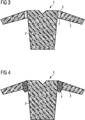
Fig. 3 : A schematic representation of an alternative embodiment of the item of clothing according to the invention with a fold-like structure; -
Fig. 4 : A schematic representation of a further alternative embodiment of the item of clothing according to the invention comprising a third textile area that is distanced further away from the skin of a wearer of the item of clothing; -
Fig. 5 : A schematic representation of a further embodiment of the item of clothing according to the invention comprising first and second textile areas that touch each other; -
Fig. 6 : A schematic representation of a further embodiment of the item of clothing according to the invention comprising two different elasticity modules; -
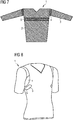
Fig. 7 : A representation of a further embodiment of the item of clothing according to the invention, in which the item of clothing is designed to arrange the sensor around the thorax of a wearer circumferentially; -
Fig. 8 : A representation of a further embodiment of the item of clothing according to the invention, in which the item of clothing comprises a circumferential third textile area and an electrical conductor that is connected to the sensor; -
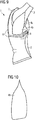
Fig. 9 : An embodiment of the item of clothing according to the invention with a third textile area comprising two sections and a measurement data processing device; -
Fig. 10 : A detailed representation of a section of a third textile area according to the embodiment ofFig. 9 ; -
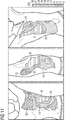
Fig. 11 : An illustration of a partial aspect of the performance of the method according to the invention; -
Fig. 12 : An illustration of a partial aspect of the performance of the method according to the invention; -
Fig. 13 : A detailed representation of a section of a third textile area in accordance with an embodiment; -
Fig. 14 : A detailed representation of a section of a third textile area with a slot in accordance with an embodiment; -
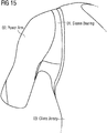
Fig. 15 : A partial view of an alternative embodiment of an item of clothing according to the invention; -
Fig. 16 : A partial view of an alternative embodiment of an item of clothing according to the invention; -
Fig. 17 : A representation with regard to locating an area of optimal position of a sensor; -
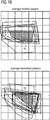
Fig. 18 : An illustration of an aspect of locating an area of optimal position of a sensor; -
Fig. 19 : An illustration of an aspect of locating an area of optimal position of a sensor for two different types of sport; - In the following, the currently preferred embodiments of the present invention are described with reference to an item of clothing as well as a method.
-
Fig. 1 shows a schematic representation of an item ofclothing 1 according to a first aspect of the present invention. In the embodiment ofFig. 1 the item ofclothing 1 is shown as a long-sleeved item of clothing for the upper part of the body, for example a football jersey for winter. Principally, the item of clothing can also be a short-sleeved shirt, for example a summer jersey, a running shirt, an undershirt, a vest, trousers, thus any item of clothing. Preferably, the item of clothing is functional clothing for sporting activities such as football or basketball. - The item of clothing is generally manufactured out of a textile fabric. The fabric can be a woven fabric, an interlaced yarn, a knitted fabric, a fleece, hence any kind of fabric manufactured out of textile fibers.
- The item of
clothing 1 shown inFig. 1 has afirst textile area 2, which is suitable to receive at least one sensor (not shown inFig. 1 ). Thefirst textile area 2 is manufactured from a textile fabric, as described above. In the item ofclothing 1 inFig. 1 the first textile area is the trunk area of the item of clothing for the upper part of the body shown. In a different item of clothing according to the invention, for example a pair of trousers, the first textile area could be the thigh area for example. - The first textile area is suitable to receive at least one sensor (not shown in
Fig. 1 ). The sensor can, for example, be received through a mount (not shown inFig. 1 ) in the form of a pocket or a clip or different fixing means. Other forms of mounts, such as hook and loop fasteners, press studs or lace fastenings are conceivable. If the sensor requires contact with the skin, then the mounting can be arranged on the inside, i.e. the side facing the body of the item of clothing that is worn the correct way around. In such a case the mount permits the contact of the sensor to the skin, for example through one or more holes. - The
first textile area 2 can also receive the sensor permanently, i.e. in a non-removable manner. For example, the sensor can be sewn, woven, knitted or glued into the first textile area. - The item of
clothing 1 shown inFig. 1 further comprises a second textile area. Thesecond textile area 3 is also manufactured out of a textile fabric, as described above. This can be the same material as that of thefirst textile area 2. Thesecond textile area 3 inFig. 1 is a sleeve-area of the item of clothing for the upper part of the body ofFig. 1 . In a different item of clothing according to the invention, for example a pair of trousers, the second textile area could be the lower leg area for example. - Furthermore, the item of
clothing 1 shown inFig. 1 comprises athird textile area 4. Also thisthird textile area 4 is manufactured out of a textile fabric, as described above. Principally, this can be a different textile fabric as that of the first and second textile area. Thethird textile area 4 shown inFig. 1 has the shape of a circumferential sleeve portion, i.e. it runs once around the arm of the wearer of the item ofclothing 1. For example, thesleeve portion 4 can be a circumferential insert substantially in the shape of a cylindrical surface. For example, the seams of the trunk and the sleeves of the T-shirt can be shortened in order to create space for the third textile area, so that the sleeve has the same length as before after the third textile area is inserted. - The
third textile area 4 is provided such that it isolates relative motions between the first and second textile area when the item of clothing is worn, so that a sensor received by the first textile area (not shown inFig. 1 ) remains substantially fixed in relation to an area of a subjacent organ of the wearer of the item of clothing. - For example, the sensor can remain substantially fixed to an area of the subjacent skin. This is particularly advantageous for heart rate electrodes, which require a transition resistance between the skin and the electrode that is as low as possible. Depending on the use, the sensor can in addition or alternatively remain substantially fixed to an internal organ, e.g. the heart or the lung.
- If the organ is the skin, for instance, then it is sufficient if the sensor remains substantially fixed to an area of the skin, which is immediately associated to the sensor. For example, it can be an area of skin that can have a diameter of several centimeters, for example 10 centimeters, on which the sensor lies and in relation to which the sensor remains substantially fixed. For the sensor to be in a position to measure the heart beat it is irrelevant whether other areas of the skin, such as on the leg, move in relation to the sensor or not.
- The function of the
third textile area 4 is illustrated inFig. 2 , which schematically shows a motion of the item ofclothing 1 from the embodiment out ofFig. 1 . InFig. 2 the item ofclothing 1 is shown after the left arm of a wearer (not shown inFig. 2 ) is raised. As a result of the provision and the arrangement of thethird textile area 4 between thefirst textile area 2 and thesecond textile area 3 the motion of thesecond textile area 3 is substantially isolated from thefirst textile area 2. Since the first textile area receives the sensor (not shown inFig. 2 ), the motion of thesecond area 3 is not passed on to the sensor. It remains substantially fixed to the subjacent skin of the wearer, i.e. the measurements it performs are not negatively influenced. - As shown in
Fig. 2 , the relative motion between thesecond textile area 3 and thefirst textile area 2 leads to a clear elongation or stretching of thethird textile area 4. This elongation or stretching can be caused in that the third textile area is more easily stretchable than the first textile area. For example, the first textile area can comprise a smaller elasticity module than the first textile area. It is known that the elasticity module of a material indicates how far the material stretches under a tensile force. Generally the elasticity module is defined as a quotient of the tensile force and the material expansion, i.e. a smaller elasticity module means that less tensile force is require for the same material expansion. In the embodiment ofFig. 1 and Fig. 2 this means that thethird textile area 4 stretches considerably more than the first and the second textile area. - A further possibility of favoring an elongation or stretching of the
third textile area 4 upon the occurrence of tensile forces is shown inFig. 3 . Here, the third textile area comprises a fold-like structure 7. Such a structure could be a pleat, i.e. artificially created folds. Other structures are also conceivable, such as for example a crease fabric or a micro three dimensional structure. As shown in the embodiment ofFig. 3 , these folds 7 can be arranged at right angles tot eh arising tensile force between the first and second textile area, circumferential around the sleeve for instance. In the event of a relative motion between the first and the second textile area, the folds 7 in thethird textile area 4 and drawn-out, i.e. the third textile area is stretched. The folds 7 thus ensure that there is a sufficient fabric reserve of thethird textile area 4 is provided for upon the occurrence of tensile forces, in order to effect an elongation or stretching. - A further possibility of favoring an elongation or stretching of the
third textile area 4 upon the occurrence of tensile forces is shown inFig. 4 . Here thethird textile area 4 is provided such that it is distanced further away from the skin of the wearer of the item of clothing than the first textile area when the item ofclothing 1 is worn. In the embodiment ofFig. 4 thethird textile area 4 below the armpits is distanced further away from the skin of the wearer (not shown inFig. 4 ) than the first and second textile area. In this embodiment thethird textile area 4 is arranged partially between the first and second textile area. Partially, namely below the armpits, the third textile area is not arranged between the first and second textile area. As a result of this measure, thethird textile area 4 has a sufficient fabric reserve in order to effect an elongation or stretching in the event of occurring tensile forces. - A further possibility of favoring an elongation or stretching of the
third textile area 4 upon the occurrence of tensile forces lies in that thethird textile area 4 has a different mechanical preliminary tension than the first and / or the second textile area. For example thethird textile area 4 can have a lower mechanical preliminary tension than the first and second textile area. In this manner thethird textile area 4 can deform more easily, when tensile stresses occur between the first and the second textile area while the item ofclothing 1 is worn. Occurring tensile forces can thus be minimized through an elongation or stretching of thethird textile area 4 and the first and second area are isolated. - A low mechanical preliminary tension of the
third textile area 4 can be achieved e.g. in that when connecting, e.g. sewing thethird textile area 4 to the first and / or second textile area the first and / or second textile area is stretched by means of tensile stress. In this manner, thethird textile area 4 receives a lower mechanical preliminary tension than the first and / or second textile area. - The above described embodiments have in common that the provision of a
third textile area 4 and its isolating arrangement between thefirst textile area 2 and thesecond textile area 3 ensure that thefirst textile area 2, which can receive a sensor, moves with the skin of the wearer of the item ofclothing 1. In this manner, a shifting of the sensor is reduced or avoided, i.e. the sensor can continue to perform measurements without interruption. The above described embodiments can for example be combined. Other approaches to isolate the first and second area through a correspondingly implemented third area are also conceivable. In the embodiments shown inFigs. 1 to 4 thefirst textile area 2 does not abut thesecond textile area 3, i.e. thethird textile area 4 divides these arrears completely. Alternatively, the first and second textile area could be arranged so that they abut, as shown in the embodiment ofFig. 5 . Here thesecond textile area 3, in the form of a sleeve area, is drawn from the top side of the sleeve to thefirst textile area 2, in the form of a trunk area, i.e. both areas touch at the top side of the sleeve in the area of the shoulder. Thethird textile area 4 is arranged on the side and underneath the armpit between thesleeve area 3 and thetrunk area 2 in the form of asleeve portion 4. Since the greatest tensile forces occur under the armpit between thesleeve area 3 andtrunk area 2, for instance during the raising motion of the arm, this arrangement of thesleeve portion 4 fulfills just as good an isolation function, like in the embodiments ofFigs. 1 to 4 . - In the embodiment of
Fig. 6 thethird textile area 4 comprises two different elasticity modules E1 and E2 in two directions that are different from one another and oriented such that the direction of the smaller elasticity module E1 is substantially parallel to the direction in which the greatest mechanical tension F occurs when wearing the item ofclothing 1. - Textile materials with different elasticity modules in two directions that are different from one another can be woven fabric, for example. Woven fabrics are made from generally perpendicular warp and weft threads. Varying thicknesses and densities of warp and weft threads and the type of interweaving can cause elasticity modules that distinctly differ from one another in the direction of the warp thread and the direction of the weft thread.
- In the embodiment of
Fig. 6 thethird textile area 4 is arranged on the item ofclothing 1 such that the direction of the smallest elasticity module E1 is substantially parallel to the direction in which the greatest mechanical tension F occurs when wearing the item of clothing. - In the example of the item of clothing for the upper part of the body of
Fig. 6 , the greatest mechanical tension F occurs at the underside of the armpit, e.g. when lifting the arm up and is directed towards thetrunk area 2 from thesleeve area 2. Correspondingly, the direction of the smallest elasticity module E1 is arranged substantially parallel to the direction of this mechanical tension F. In this manner a stretching of the third textile area upon occurrence of tensile stress is further favored and a shifting of the sensor is reduced or avoided. -
Fig. 7 shows a further embodiment of the present invention, in which the item ofclothing 1 is designed to arrange asensor 5 circumferentially so that it at least partially runs around the torso of the wearer of the item ofclothing 1 when the item of clothing is worn. For example, it can be a meander-shaped electrical conductor, which is used to measure respiration. For measuring respiration thesensor 5, for example, has meander-shaped electrical conductors which respectively represent an electrical coil and can be connected to an electrical oscillator. Due to the respiratory motions the circumference of the chest and abdomen alter and thus the length of the conductors, the inductance of the coils and finally the oscillation frequency. The alteration of the oscillation frequency can be evaluated and permits conclusions to be made with regard to the respiratory motions. -
Fig. 8 shows a representation of another embodiment of the item ofclothing 1 according to the invention, in which the item ofclothing 1 comprises a circumferentialthird textile area 4 and anelectrical conductor 6 that is connected to thesensor 5. The electrical conductor can, for example, lead to a measurement data processing device (not shown inFig. 8 ), which is arranged at the item ofclothing 1 and processes or stores or wirelessly transmits the data measured bysensor 5 to a receiver. -
Fig. 9 shows a further embodiment of the item ofclothing 1 according to the invention with athird textile area 4 comprising twosections third textile area 4 comprises asection 4a surrounding the arm in the shoulder area and alongitudinal section 4b that extends from the lateral thorax area under the armpit to the upper arm area. Furthermore, anarea 8 optimal for the function of the sensor is shown inFig. 9 . If the sensor, which in this embodiment is a heart rate electrode, positioned in this area, then it is able to measure the heart rate of a wearer of the item ofclothing 1. The measurement data processing device 7 is connected to the heart rate electrode by means of anelectrical conductor 6. This conductor can be flexible and exhibit a similar stretch behavior to the textile area in which it is arranged. -
Fig. 10 shows a detailed representation of asection 4b of athird textile area 4 according to the embodiment ofFig. 9 . Thesection 4b is elongated and has a tapered shape. As a result of this cut, an optimal isolation of the first and second area is made possible. -
Fig. 11 shows an illustration of a partial aspect of the performance of the method according to the invention. Here, the stretching pattern of the skin of a wearer, namely an athlete, was recorded during a sport-specific motion, namely a throw-in during football, by means of an optical method. In this Figure, the stretching of the skin is shown as a relative stretching compared to the skin's state of rest, for instance during upright casual standing with hanging arms. Thus, a relative stretching of 100% in a specific area of the skin means that the skin in this area has stretched to twice its length. A stretching of 30% would, for example, mean that a previously 1 cm long piece of skin has stretched to a length of 1.3 cm. - As shown in
Fig. 11 , the greatest stretching of 25% to 60% occurs inarea 9. In area 10 a stretching of 20% to 25% is reflected. Inarea 11, a stretching of 10% to 20% and inarea 12, a stretching of 0% to 10% is reflected. As shown inFig. 11 , during a throw-in, the greatest stretching of the skin occurs below the armpit between the mid-lateral thorax area and mid-lateral back area. - After the stretching pattern shown as an example in
Fig. 11 was recorded, an item of sports clothing is manufactured in accordance with the method according to the invention, whereby the item of sports clothing exhibits a substantially similar stretching pattern to the stretching pattern of the skin when worn. - The stretching pattern of the item of sports clothing is similar to the stretching pattern of the skin so much so that a sensor received by the item of sports clothing, such as a heart rate electrode for instance, remains substantially fixed to an area of a subjacent organ of the wearer of the item of sports clothing during the specific motions of a wearer of the item of sports clothing. This means that the sensor does not shift during the specific motions of the wearer such that a measuring is constantly no longer possible.
- The method according to the invention permits the manufacture of an item of sports clothing, which is suitable to receive a sensor and thus permits a measurement of physiological data of a wearer of the item of sports clothing in real-time during natural motion sequences, without there being a constant "loss" of the measuring signal. For example, in accordance with the method according to the invention the item of sports clothing can be adapted for a specific type of sport or a group of sports, in that when recording the stretching pattern of the skin at least one motion specific to the sport is performed.
- An athlete of a field sport e.g., who wears an item of sports clothing manufactured in accordance with the method according to the invention, does not need to leave the sports field, in order to correct the position of the sensor. Even in relatively "rough" sports such as rugby, the fixture of the sensor is guaranteed.
-
Fig. 12 shows an illustration of a partial aspect of the performance of the method according to the invention. In this Figure, the stretching of an item of sports clothing according 1 to the invention is shown. The stretching of the item of sports clothing was measured here using the same method as the stretching of the skin inFig. 11 . The areas of different stretching correspond to those inFig. 11 . The least stretching, between 0% and 10%, occurs inarea 12. This area is best suited for the positioning of the sensor, since the sensor and/or the stretchable electric feed for the sensor, since the sensor and/or the stretchable electric feed will shift the lease or not at all in this area during a sport-specific motion, such as a throw-in for instance. The sensor and/or the stretchable electric feed can also be positioned inarea 11, which exhibits a stretching of 10% to 20%. - Preferably, a stretchable electric feed for the sensor has the same stretching behavior, e.g. expressed by means of an elasticity module, as the area of the item of sports clothing in which the stretchable electric feed is attached.
- The stretching scale, shown in
Fig. 11 and12 , ranges from 0% to 30%. However, stretching beyond 30% also occurs in theareas 9 shown inFig. 11 and12 , for example 60%. In the explanation ofFig. 11 and12 , the stretching was divided into four areas, namely 12: 25% to 60%, 11: 20% to 25%, 10: 10% to 20% and 9: 0% to 10%. Other divisions, grosser or finer, are possible of course. Likewise, the stretching scale can be adapted to larger or smaller maximum occurring stretches, depending on e.g. sport-specific motion or sport. -
Fig. 13 shows a detailed representation of asection 4b of a third textile area according to an embodiment. Insection 4b, the third textile area has an elasticity of more than 30%, preferably more than 60%. -
Fig. 14 shows a detailed representation of asection 4b of a third textile area with aslot 13 according to an embodiment. The slot in the third textile area can additionally favor the isolation between the first and second textile area, in that it prevents or reduces the raising of the first textile area, e.g. during a throw-in during football. -
Fig. 15 shows a partial view of an alternative embodiment of an item of clothing according to the invention. Compared to the previous embodiments, this embodiment has a different cut, particularly in the third area. -
Fig. 16 shows a partial view of an alternative embodiment of an item of clothing according to the invention, which is suitable for the sport of basketball. Here, a part of thethird textile area 4 is positioned below the armpit in the shape of a diamond. - It is important that a sensor received by the item of clothing according to the invention is positioned as optimally as possible. The following method can be applied for this:
The method concerns the determination of an area for possible positions of a sensor on an item of clothing, whereby the sensor is suitable to measure physiological data of a wearer of the item of clothing and whereby the method comprises the steps: a. Putting on the item of clothing by a first wearer; b. Marking areas of possible positions of the sensor on the item of clothing specific to the first wearer; c. Repeating steps a and b for at least a second wearer; and d. Determining an overlapping area of the specific area of possible positions of the sensor of the first and second wearer. - The overlapping area can be determined directly, but also indirectly, for example by means of a reverse conclusion of the examination of all areas, in which the possible sensor positions of the first and second wearer do not overlap. The overlapping area can also be determined in that the area specific for the second wearer is only determined within the specific area for the first wearer. Correspondingly, the area specific for a third wearer would only be determined within the specific area for the second wearer, and so on. In this manner, the overlapping area is continuously narrowed down.
- The method ensures that the sensor or a mount therefore is positioned as optimally as possible on the item of clothing, so that a slight shift can be tolerated. Generally, items of clothing are offered in different sizes, for example S (for "small"), M (for "medium"), L (for "large") and XL (for "extra large"), if necessary with increments to smaller and larger sizes. As a rule, items made-to-measure are not particularly found in the leisure and sports sector, but are also possible there - e.g. in high-performance sport. For this reason, one specific size should fit as large a number of different wearer-anatomies as possible. As is know people who share the same cloths size do not share the same anatomy, but rather there are great differences, for instance with regard to the circumference, the arm and leg length, shoulder and hip width, and so on.
- The method permits the determination of an area on the item of clothing, which is optimal for the positioning of the sensor for a plurality of different wearer-anatomies. This area is the overlapping area determined by means of the method. As a result of the method it is guaranteed that the sensor or a mount therefore is positioned on the item of clothing such that it lays upon the organ to be measured in a large a number of different wearers as possible in a manner that a measurement of physiological data of said organ is possible. As a result of this positioning a slight shift can be tolerated since the sensor sill lies within the optimal area determined by means of the method. If the sensor were already positioned in an area that was not optimal for the measurement, for instance positioned at a peripheral area of the organ, immediately after the item of clothing is put on, thus prior to any activity, then a slight shift could lead to the sensor distancing itself too far away from the optimal are. A measurement would then no longer be possible.
- In a preferred embodiment, the method further comprises the step: Application of a reference mark on the item of clothing. Preferably, this occurs prior to step a. However, it is equally possible not to apply the reference mark until after step a. A reference mark permits the comparison between the specific areas of possible positions of the sensor for different wearers in an easy manner. The electronic measurement and processing in the course of the method are facilitated by means of a reference mark.
- Preferably, the reference mark is a grid. This facilitates the measurement of the specific areas of possible positions of the sensor for different wearers, in that the coordinates of the areas can be determined relative to the grid.
-
Fig. 17 shows a representation regarding the finding of an area of optimal position of a sensor. InFig. 17 a grid is shown as a reference mark. Furthermore, the optimal area for the sensor on the item of clothing was determined for the current wearer and correspondingly marked on the item of clothing. This lies between the underside of the chest muscle (musculus pectoralis major) and the bottom edge of the ribcage, e.g. in the region of the costal arch (arcus costalis). This position permits, on the one hand, a good measuring signal of the sensor in a state of rest of a wearer of the item of clothing. On the other hand, a "loss" of the signal during motions, e.g. during sport, of the wearer are reduced or avoided. - Preferably, the method comprises the step: Electronic recording of the specific areas of possible positions of the senor of the first and second wearers with regard to the reference mark. An electronic recording permits a simple electronic processing and evaluation in the course of the method.
- It is further preferred that the method comprises the step: Superimposing the specific areas of possible positions of the sensor of the at least two wearers using the reference mark. Through superimposing the specific areas of possible positions of the sensor of different wearers, the overlapping area can easily be determined as an intersection. However, other methods of direct and indirect determination of the overlapping area are also possible.
- In a preferred embodiment of the method, the specific areas of possible positions of the sensor for the first and second wearer are limited by an underside of a chest muscle (musculus pectoralis major) and a bottom edge of the ribcage, e.g. in the region of the costal arch (arcus costalis). Such a limited area is an area that is relevant for the determination of the heartbeat, i.e. a sensor that is suitable for measuring a heartbeat, an electrode for instance, should be positioned in this area.
- In a preferred embodiment of the method, the first and second wearers are respectively athletes of different type of sport. It is hereby guaranteed that the position of the sensor is optimal during the performance of different types of sport, such as football and basketball, and that a slight shift of the sensor can be tolerated.
-
Fig. 18 shows an illustration of this aspect of the described method for finding an area of optimal position of a sensor. The optimal areas for different average football players is shown on the left hand side, while the optimal areas for different average basketball players is shown on the right hand side. From the different optimal areas of the football players results the overlappingarea 14, which is optimal for a large proportion of football players, if the football players used for the performance of the method correspond to the average population and/or buyer. The same applies for the overlappingarea 15 on the right hand side for the average basketball players. -
Fig. 19 shows an illustration of an aspect of the finding of an area of optimal position of a sensor for two different types of sport. In this Figure, theareas Fig. 18 have been overlapped so that anarea 16 results, in which the sensor is positioned optimally for both football as well as basketball. - In a further preferred embodiment of the method, the specific area for the first or second wearer comprises all positions in which the sensor is able to measure physiological data of the first or second wearer.
- A further aspect of the present invention concerns an item of clothing with at least one mounting device for a sensor, whereby the position of the mounting device for the sensor in the item of clothing has been determined by means of a method, which comprises the determination of an area of possible positions of the sensor on the item of clothing according to the above described method. The mounting device, for example a pocket or a clip, fixes the sensor on the item of clothing and thus determines its position on the item of clothing. The position of the sensor and thus the position of the mounting device is determined in accordance with the above described method, so that the position of the sensor and thus that of the mounting device is optimal for a plurality of different wearer-anatomies and so that a slight shift of the sensor can be tolerated, without the measurement performed by means of the sensor is negatively influenced. As a result, the items of clothing according to the invention differ even from items of clothing for receiving sensors that are previously known from the prior art.
- A further aspect of the present invention concerns an item of clothing comprising at least one sensor, whereby the position of the sensor in the item of clothing was determined by a method, which comprises the determination of an area of possible positions of the sensor on the item of clothing in accordance with the above described method. It is hereby guaranteed that the position of the sensor is optimal for a plurality of different wearer-anatomies and that a slight shift of the sensor can be tolerated, without the measurement performed by means of the sensor is negatively influenced. It also applies here that the position determination by means of using the method according to the invention significantly determines the measurement accuracy and the reliability of the sensor function of the item of clothing according to the invention.
- In the following, further examples are described to facilitate the understanding of the invention:
- 1. Item of clothing, comprising:
- a. a first textile area, which is suitable to receive at least one sensor;
- b. a second textile area; and
- c. a third textile area, which is arranged at least partially between the first and second textile areas,
- 2. Item of clothing according to example 1, whereby a material processed into the third textile area can be stretched more easily than a material processed into the first textile area.
- 3. Item of clothing according to one of the preceding examples, whereby the third textile area comprises an uneven structure.
- 4. Item of clothing according to one of the preceding examples, whereby the third textile area is provided such that when the item of clothing is worn it is spaced further away from the skin of a wearer of the item of clothing than the first textile area.
- 5. Item of clothing according to one of the preceding examples, whereby the third textile area has a substantially different mechanical preliminary tension than the first and / or the second textile area.
- 6. Item of clothing according to one of the preceding examples, whereby the third textile area comprises a longish section substantially along the direction of greatest stretching when wearing the item of clothing.
- 7. Item of clothing according to one of the preceding examples, whereby the organ is the skin, the heart, the lung, the thorax or the abdomen of a wearer of the item of clothing.
- 8. Item of clothing according to one of the preceding examples, whereby the third textile area is arranged between the first and second textile areas such that the first and second textile areas do not abut.
- 9. Item of clothing according to one of the preceding examples, whereby it is an item of clothing for the upper part of the body, whereby the first textile area is a trunk area and whereby the second textile area is sleeve area.
- 10. Item of clothing according to example 9, whereby the third textile area is a circumferential sleeve piece.
- 11. Item of clothing according to one of the preceding examples, whereby the first textile area comprises a pocket or a clip for receiving the sensor.
- 12. Item of clothing according to one of the preceding examples, whereby the sensor is sewn, woven, knitted or glued into the first textile area.
- 13. Item of clothing according to one of the preceding examples, whereby the third textile area is a fabric.
- 14. Item of clothing according to one of the preceding examples, whereby the first and second textile areas have the same material.
- 15. Item of clothing according to one of the preceding examples, whereby the third textile area comprises two different elasticity modules in two directions that are different from one another and oriented such that the direction of the smaller elasticity module is substantially parallel to the direction in which the greatest mechanical tension occurs when wearing the item of clothing.
- 16. Item of clothing according to one of the preceding examples, whereby the item of clothing is designed to arrange the sensor such that it is positioned on one side of the torso of a wearer of the item of clothing when the item of clothing is worn.
- 17. Item of clothing according to one of the preceding examples, whereby the item of clothing is designed to arrange the sensor circumferentially so that it at least partially runs around the torso of a wearer of the item of clothing.
- 18. Item of clothing according to one of the preceding examples, whereby the sensor is a textile sensor with a substantially equal stretching behavior as the first textile area and/or the skin of a wearer of the item of clothing.
- 19. Item of clothing according to one of the preceding examples, whereby the sensor is a heart rate electrode and whereby the item of clothing is designed to arrange the sensor such that it is arranged in a lateral chest area of the wearer of the item of clothing.
- 20. Item of clothing according to one of the preceding examples, whereby the sensor is a heart rate electrode, which communicates with a data transmission device.
- 21. Method for manufacturing an item of sports clothing, whereby the method comprises the steps:
- a. Obtaining the stretching pattern of the skin of the wearer of the item of sports clothing during at least one sport-specific motion of the wearer;
- b. Manufacturing the item of sports clothing, whereby the item of sports clothing exhibits a substantially similar stretching pattern to the stretching pattern of the skin during the sport-specific motion of the wearer and is suitable to receive a sensor.
- 22. Method according to example 21, whereby step b. is designed such that the stretching pattern of the item of sports clothing is provided such that when wearing the item of sports clothing a sensor received by said item of sports clothing is substantially fixed in relation to an area of a subjacent organ of a wearer of the item of clothing.
- 23. Method according to example 22, whereby the organ is the skin, the heart, the lung, the thorax or the abdomen of a wearer of the item of sports clothing.
- 24. Method according to one of examples 21 to 23, whereby step b. further comprises the step:
- Attaching a mounting for a sensor to the item of sports clothing.
- 25. Method according to one of examples 21 to 24, whereby step b. further comprises the step:
Attaching a sensor to the item of sports clothing. - 26. Method according to one of examples 24 to 25, whereby the mounting and/or the sensor are arranged in an area of little stretching in comparison to other areas of the stretching pattern of the item of sports clothing.
- 27. Method according to one of examples 21 to 26, whereby a textile area is incorporated in an area of great stretching in comparison to other areas of the stretching pattern of the item of sports clothing, which is easier to stretch than other textile areas.
- 28. Method according to one of examples 21 to 27, whereby obtaining of the stretching pattern in step a. takes place by means of an optical method.
- 29. Method according to one of examples 21 to 28, whereby step b. further comprises:
Forming at least two textile areas of the item of sports clothing with different stretching behaviors. - 30. Item of sports clothing, which was manufactured pursuant to the method according to one of the examples 21 to 29.
Claims (10)
- A method for manufacturing an item of sports clothing comprising:(a) obtaining a stretching pattern of at least a portion of skin of a wearer of the item of sports clothing during at least one sport-specific motion of the wearer;(b) manufacturing the item of sports clothing, wherein the item of sports clothing exhibits a stretching pattern substantially similar to the stretching pattern of at least a portion of skin during the sport-specific motion of the wearer, and wherein the item of sports clothing is adapted to receive a sensor.
- The method according to claim 1, wherein step (b) includes manufacturing the item of sports clothing such that the stretching pattern of the item of sports clothing is configured so a sensor would be substantially fixed in relation to an area of a subjacent organ of the wearer of the item of sports clothing.
- The method according to claim 2, wherein the organ is the skin, a heart, a lung, a thorax, or an abdomen of the wearer of the item of sports clothing.
- The method according to one of claims 1-3, wherein step (b) further includes attaching a mounting for a sensor to the item of sports clothing.
- The method according to one of claims 1-4, wherein step (b) further includes attaching a sensor to the item of sports clothing.
- The method according to one of claims 1-5, wherein step (b) further includes manufacturing the item of sport clothing such that a first portion is less stretchable than a second portion, and wherein the first portion of the item of sports clothing is configured to receive a mounting for a sensor or a sensor.
- The method according to one of claims 1-6, wherein a textile area is incorporated in an area that is more stretchable than other areas of the stretching pattern of the item of sports clothing.
- The method according to one of claims 1-7, wherein obtaining the stretching pattern includes using an optical method.
- The method according to one of claims 1-8, wherein step (b) further includes forming at least two textile areas of the item of sports clothing with different stretching abilities.
- An item of sports clothing manufactured pursuant to the method according to one of claims 1-9.
Applications Claiming Priority (2)
| Application Number | Priority Date | Filing Date | Title |
|---|---|---|---|
| DE102012218068.0A DE102012218068B4 (en) | 2012-10-02 | 2012-10-02 | ITEM OF GARMENT |
| EP13187017.2A EP2716172B1 (en) | 2012-10-02 | 2013-10-02 | Item of clothing |
Related Parent Applications (1)
| Application Number | Title | Priority Date | Filing Date |
|---|---|---|---|
| EP13187017.2A Division EP2716172B1 (en) | 2012-10-02 | 2013-10-02 | Item of clothing |
Publications (3)
| Publication Number | Publication Date |
|---|---|
| EP3524074A1 true EP3524074A1 (en) | 2019-08-14 |
| EP3524074B1 EP3524074B1 (en) | 2023-08-30 |
| EP3524074B8 EP3524074B8 (en) | 2023-10-11 |
Family
ID=49304732
Family Applications (2)
| Application Number | Title | Priority Date | Filing Date |
|---|---|---|---|
| EP13187017.2A Active EP2716172B1 (en) | 2012-10-02 | 2013-10-02 | Item of clothing |
| EP19151644.2A Active EP3524074B8 (en) | 2012-10-02 | 2013-10-02 | Item of clothing |
Family Applications Before (1)
| Application Number | Title | Priority Date | Filing Date |
|---|---|---|---|
| EP13187017.2A Active EP2716172B1 (en) | 2012-10-02 | 2013-10-02 | Item of clothing |
Country Status (5)
| Country | Link |
|---|---|
| US (1) | US20140090146A1 (en) |
| EP (2) | EP2716172B1 (en) |
| JP (1) | JP6308745B2 (en) |
| CN (2) | CN106388775B (en) |
| DE (1) | DE102012218068B4 (en) |
Families Citing this family (26)
| Publication number | Priority date | Publication date | Assignee | Title |
|---|---|---|---|---|
| FI123363B (en) | 2011-01-31 | 2013-03-15 | Clothing Plus Holding Oy | Substrate of textile for measuring a physical quantity |
| US9717970B2 (en) * | 2014-01-21 | 2017-08-01 | A. Alex Wortman | Sleeve to improve swinging motion |
| US10197417B2 (en) | 2014-09-09 | 2019-02-05 | Twin Harbor Labs, LLC | Monitoring activity with intelligent fabrics |
| US9330558B2 (en) | 2014-09-09 | 2016-05-03 | Twin Harbor Labs, LLC | Intelligent fabrics |
| US9662030B2 (en) | 2014-10-01 | 2017-05-30 | Verily Life Sciences Llc | Electrocardiography device for garments |
| CN105559786A (en) * | 2014-10-14 | 2016-05-11 | 苏扬修 | Underwear that counts calories |
| EP3028587B1 (en) | 2014-12-03 | 2020-03-11 | Clothing Plus MBU Oy | Device for determining effects of aging of a wearable device |
| US20160255883A1 (en) * | 2015-03-05 | 2016-09-08 | Delta Galil Industries Ltd. | Tights, leggings, pants, and other articles of clothing |
| US9750291B2 (en) | 2015-03-05 | 2017-09-05 | Delta Galil Industries Ltd. | Shirt, and other articles of clothing |
| JP6682796B2 (en) * | 2015-10-09 | 2020-04-15 | タカヤ株式会社 | Sensing type clothing and management system |
| US10165813B2 (en) * | 2015-12-18 | 2019-01-01 | Nike, Inc. | Sleeve gusset for an apparel item |
| JP6926500B2 (en) * | 2016-02-12 | 2021-08-25 | 東洋紡株式会社 | Clothes-type electronic equipment |
| US10310558B2 (en) * | 2017-04-25 | 2019-06-04 | Intel Corporation | Apparatus and method for computing node and seat connection for conductive fabric |
| WO2019016973A1 (en) * | 2017-07-19 | 2019-01-24 | トラタニ株式会社 | Upper body part of garment |
| CN107625520B (en) * | 2017-09-25 | 2020-12-18 | 联想(北京)有限公司 | Sign signal detection electrode and intelligent clothing |
| JPWO2020031922A1 (en) * | 2018-08-07 | 2021-08-26 | ミツフジ株式会社 | clothes |
| CN111513672A (en) * | 2019-02-01 | 2020-08-11 | 新华生物科技股份有限公司 | Wearable device |
| GB2587255B (en) * | 2019-07-12 | 2023-02-01 | Prevayl Innovations Ltd | Biosensing garment and method |
| GB2585827B (en) * | 2019-07-12 | 2021-10-27 | Prevayl Ltd | Biosensing garment and method |
| US20230135094A1 (en) * | 2020-03-19 | 2023-05-04 | Toyobo Co., Ltd. | Garment |
| JP7505953B2 (en) * | 2020-09-29 | 2024-06-25 | 帝人フロンティア株式会社 | Wearable Best Clothing |
| USD1003173S1 (en) * | 2020-10-28 | 2023-10-31 | ZOZO, Inc. | Measuring instrument other than for measuring time |
| CN112587117A (en) * | 2020-12-25 | 2021-04-02 | 苏州益舒缘科技有限公司 | Detection device and detection method for monitoring heart rate in real time |
| CN112587113A (en) * | 2020-12-25 | 2021-04-02 | 苏州益舒缘科技有限公司 | Device for heart rate detection |
| JP7845652B2 (en) * | 2021-02-22 | 2026-04-14 | 国立大学法人 東京大学 | Wearable sensing device |
| JP2023003530A (en) * | 2021-06-24 | 2023-01-17 | 国立大学法人信州大学 | Electrode position determination method |
Citations (4)
| Publication number | Priority date | Publication date | Assignee | Title |
|---|---|---|---|---|
| JPH1161530A (en) * | 1997-08-19 | 1999-03-05 | Mizuno Corp | Athletic shirt |
| US20110184270A1 (en) * | 2010-01-26 | 2011-07-28 | Brian Russell | Physiological monitoring garment |
| JP2012007252A (en) * | 2010-06-22 | 2012-01-12 | Ni Teijin Shoji Co Ltd | Golf shirt |
| US20120011635A1 (en) * | 2006-09-28 | 2012-01-19 | Yoshie Tsuji | Wear |
Family Cites Families (39)
| Publication number | Priority date | Publication date | Assignee | Title |
|---|---|---|---|---|
| US1169256A (en) * | 1915-07-01 | 1916-01-25 | Louis Grimm | Garment. |
| US2554380A (en) * | 1947-11-15 | 1951-05-22 | Munsingwear Inc | Garment |
| US2941210A (en) * | 1958-04-21 | 1960-06-21 | Munsingwear Inc | Garments |
| US3037210A (en) * | 1959-11-16 | 1962-06-05 | Harold L Neuman | Sleeve insert for garment |
| US3137860A (en) * | 1961-07-25 | 1964-06-23 | Freezer & Son Inc J | Sport shirts |
| DE2205305A1 (en) * | 1972-02-04 | 1973-08-09 | Heinz Leupold Bekleidungswerk | Outerwear arm attachment - giving freedom of movement in sports wear |
| US3801987A (en) * | 1972-05-19 | 1974-04-09 | M Thompson | Garment |
| US6080690A (en) * | 1998-04-29 | 2000-06-27 | Motorola, Inc. | Textile fabric with integrated sensing device and clothing fabricated thereof |
| US5906004A (en) * | 1998-04-29 | 1999-05-25 | Motorola, Inc. | Textile fabric with integrated electrically conductive fibers and clothing fabricated thereof |
| JP3062695U (en) * | 1999-04-02 | 1999-10-08 | 株式会社コーコス信岡 | Applicable clothing |
| US20020124295A1 (en) * | 2000-10-30 | 2002-09-12 | Loel Fenwick | Clothing apparatus, carrier for a biophysical sensor, and patient alarm system |
| US6755795B2 (en) * | 2001-10-26 | 2004-06-29 | Koninklijke Philips Electronics N.V. | Selectively applied wearable medical sensors |
| US6892396B2 (en) * | 2002-05-23 | 2005-05-17 | Mizuno Corporation | Undershirt |
| EP1651068A4 (en) * | 2003-07-14 | 2007-12-05 | Bagir Co 1961 Ltd | An item of apparel |
| US7559902B2 (en) * | 2003-08-22 | 2009-07-14 | Foster-Miller, Inc. | Physiological monitoring garment |
| EP1731094B1 (en) * | 2004-03-24 | 2014-02-26 | Nihon Kohden Corporation | Garment with a respiratory information analysis device |
| US7173437B2 (en) * | 2004-06-10 | 2007-02-06 | Quantum Applied Science And Research, Inc. | Garment incorporating embedded physiological sensors |
| DE102004030261A1 (en) * | 2004-06-23 | 2006-01-19 | Deutsche Institute für Textil- und Faserforschung (DITF) | Garment with integrated sensors |
| GB0414731D0 (en) * | 2004-07-01 | 2004-08-04 | Koninkl Philips Electronics Nv | A fabric sensor and a garment incorporating the sensor |
| US20060048265A1 (en) * | 2004-08-16 | 2006-03-09 | Deadwyler Stephen D | T-shirt with sleeve extensions |
| ITPI20040060A1 (en) * | 2004-09-06 | 2004-12-06 | Smartex Srl | METHOD AND APPARATUS FOR MONITORING OF PHYSIOLOGICAL VARIABLES THROUGH BODY ELECTRIC MEASUREMENT MEASUREMENTS |
| JP4018682B2 (en) * | 2004-09-21 | 2007-12-05 | 株式会社アシックス | spats |
| WO2006032096A1 (en) * | 2004-09-23 | 2006-03-30 | Skins Compression Garments Pty Limited | Compression garments and a method of manufacture |
| US20070055151A1 (en) * | 2005-01-20 | 2007-03-08 | Shertukde Hemchandra M | Apparatus and methods for acoustic diagnosis |
| US20060211937A1 (en) * | 2005-03-17 | 2006-09-21 | Robert Eldridge | Garment to facilitate use of a portable monitor device |
| CA2504416A1 (en) * | 2005-04-18 | 2006-10-18 | Jeffrey W. Louis | Stretchable hybrid material garment |
| JP4431616B2 (en) * | 2005-07-08 | 2010-03-17 | 株式会社アシックス | Wear |
| US20070028351A1 (en) * | 2005-07-19 | 2007-02-08 | Coolik Michael A | Garment with improved sleeve movement |
| US8188868B2 (en) * | 2006-04-20 | 2012-05-29 | Nike, Inc. | Systems for activating and/or authenticating electronic devices for operation with apparel |
| JP2007303024A (en) * | 2006-05-11 | 2007-11-22 | Shimano Inc | Bicycle-riding garment |
| US20080184455A1 (en) * | 2007-02-06 | 2008-08-07 | Blume Patricia W | Gown for cardiac patients and other specialty uses |
| US7996056B2 (en) * | 2007-06-15 | 2011-08-09 | The General Electric Company | Method and apparatus for acquiring physiological data |
| CN201789969U (en) * | 2009-12-27 | 2011-04-13 | 刘勇 | Sportswear with improved sleeves and trousers legs |
| US9775561B2 (en) * | 2010-12-23 | 2017-10-03 | Covidien Lp | System method and device for monitoring physiological parameters of a person |
| FI123363B (en) * | 2011-01-31 | 2013-03-15 | Clothing Plus Holding Oy | Substrate of textile for measuring a physical quantity |
| CN102524998A (en) * | 2011-03-29 | 2012-07-04 | 上海工程技术大学 | Optimal design method for improving comfort degree of golf clothing |
| US8818478B2 (en) * | 2011-03-31 | 2014-08-26 | Adidas Ag | Sensor garment |
| US20140296651A1 (en) * | 2013-04-01 | 2014-10-02 | Robert T. Stone | System and Method for Monitoring Physiological Characteristics |
| US20150335947A1 (en) * | 2013-12-20 | 2015-11-26 | Sensilk Inc. | Sports device and system |
-
2012
- 2012-10-02 DE DE102012218068.0A patent/DE102012218068B4/en active Active
-
2013
- 2013-10-01 JP JP2013206032A patent/JP6308745B2/en active Active
- 2013-10-01 US US14/043,365 patent/US20140090146A1/en not_active Abandoned
- 2013-10-02 EP EP13187017.2A patent/EP2716172B1/en active Active
- 2013-10-02 EP EP19151644.2A patent/EP3524074B8/en active Active
- 2013-10-08 CN CN201610793868.0A patent/CN106388775B/en active Active
- 2013-10-08 CN CN201310464595.1A patent/CN103704898B/en active Active
Patent Citations (4)
| Publication number | Priority date | Publication date | Assignee | Title |
|---|---|---|---|---|
| JPH1161530A (en) * | 1997-08-19 | 1999-03-05 | Mizuno Corp | Athletic shirt |
| US20120011635A1 (en) * | 2006-09-28 | 2012-01-19 | Yoshie Tsuji | Wear |
| US20110184270A1 (en) * | 2010-01-26 | 2011-07-28 | Brian Russell | Physiological monitoring garment |
| JP2012007252A (en) * | 2010-06-22 | 2012-01-12 | Ni Teijin Shoji Co Ltd | Golf shirt |
Also Published As
| Publication number | Publication date |
|---|---|
| EP3524074B1 (en) | 2023-08-30 |
| DE102012218068B4 (en) | 2025-10-09 |
| CN103704898A (en) | 2014-04-09 |
| DE102012218068A1 (en) | 2014-04-03 |
| EP2716172A3 (en) | 2015-10-14 |
| JP6308745B2 (en) | 2018-04-11 |
| EP2716172A2 (en) | 2014-04-09 |
| CN106388775A (en) | 2017-02-15 |
| CN103704898B (en) | 2016-10-05 |
| CN106388775B (en) | 2019-09-06 |
| JP2014074258A (en) | 2014-04-24 |
| EP3524074B8 (en) | 2023-10-11 |
| US20140090146A1 (en) | 2014-04-03 |
| EP2716172B1 (en) | 2019-01-16 |
Similar Documents
| Publication | Publication Date | Title |
|---|---|---|
| EP2716172B1 (en) | Item of clothing | |
| US11037462B2 (en) | Garment with stretch sensors | |
| CN105007769B (en) | Method for limiting the elasticity of selection area in knitted fabric | |
| CN111616430B (en) | Apparatus, system, and method for optimizing and masking compression in biosensing garments | |
| KR101536139B1 (en) | Textile electrode kit, and the motion artifact-minimizing clothing installed with the kit | |
| KR20110086796A (en) | clothing | |
| JP6409143B1 (en) | clothing | |
| KR101912730B1 (en) | A garment-like device for monitoring a user's physiological parameters | |
| KR20220042426A (en) | undergarments medical | |
| CN109068772A (en) | Clothing | |
| CN213486991U (en) | Close-fitting clothes and close-fitting clothes applied to human body data acquisition | |
| JP2018130551A (en) | Abdominal pressure belt, clothing and method of wearing the abdominal pressure belt | |
| EP3806683B1 (en) | Sports garment for team sports | |
| JP6328215B1 (en) | Abdominal pressure belt, clothing and method of wearing the abdominal pressure belt | |
| CN109996491B (en) | Wearable Electrodes | |
| JP7542745B2 (en) | Bottom clothing | |
| US20240344249A1 (en) | Knitted strain sensor | |
| WO2023013249A1 (en) | Biological information measurement clothing | |
| Paiva¹ et al. | Design of a Long Sleeve T-Shirt with ECG | |
| HK1233203A1 (en) | Devices and methods for obtaining workable ecg signals using dry knitted electrodes | |
| HK1211808B (en) | Method for limiting elasticity of selected regions in knitted fabrics | |
| HK1158033A (en) | Garment |
Legal Events
| Date | Code | Title | Description |
|---|---|---|---|
| PUAI | Public reference made under article 153(3) epc to a published international application that has entered the european phase |
Free format text: ORIGINAL CODE: 0009012 |
|
| STAA | Information on the status of an ep patent application or granted ep patent |
Free format text: STATUS: REQUEST FOR EXAMINATION WAS MADE |
|
| 17P | Request for examination filed |
Effective date: 20190114 |
|
| AC | Divisional application: reference to earlier application |
Ref document number: 2716172 Country of ref document: EP Kind code of ref document: P |
|
| AK | Designated contracting states |
Kind code of ref document: A1 Designated state(s): AL AT BE BG CH CY CZ DE DK EE ES FI FR GB GR HR HU IE IS IT LI LT LU LV MC MK MT NL NO PL PT RO RS SE SI SK SM TR |
|
| RIN1 | Information on inventor provided before grant (corrected) |
Inventor name: THE OTHER INVENTORS HAVE WAIVED THEIR RIGHT TO BE Inventor name: DEBORAH, YEOMANS Inventor name: DAVID, O'MAHONY Inventor name: BETTINA, SEIDER Inventor name: JAMES MICHAEL, TARRIER |
|
| STAA | Information on the status of an ep patent application or granted ep patent |
Free format text: STATUS: EXAMINATION IS IN PROGRESS |
|
| 17Q | First examination report despatched |
Effective date: 20200805 |
|
| GRAP | Despatch of communication of intention to grant a patent |
Free format text: ORIGINAL CODE: EPIDOSNIGR1 |
|
| STAA | Information on the status of an ep patent application or granted ep patent |
Free format text: STATUS: GRANT OF PATENT IS INTENDED |
|
| INTG | Intention to grant announced |
Effective date: 20210823 |
|
| GRAJ | Information related to disapproval of communication of intention to grant by the applicant or resumption of examination proceedings by the epo deleted |
Free format text: ORIGINAL CODE: EPIDOSDIGR1 |
|
| STAA | Information on the status of an ep patent application or granted ep patent |
Free format text: STATUS: EXAMINATION IS IN PROGRESS |
|
| INTC | Intention to grant announced (deleted) | ||
| GRAP | Despatch of communication of intention to grant a patent |
Free format text: ORIGINAL CODE: EPIDOSNIGR1 |
|
| STAA | Information on the status of an ep patent application or granted ep patent |
Free format text: STATUS: GRANT OF PATENT IS INTENDED |
|
| RIN1 | Information on inventor provided before grant (corrected) |
Inventor name: THE OTHER INVENTORS HAVE WAIVED THEIR RIGHT TO BE THUS MENTIONED. Inventor name: SEIDER, BETTINA Inventor name: TARRIER, JAMES MICHAEL Inventor name: O'MAHONY, DAVID Inventor name: YEOMANS, DEBORAH |
|
| INTG | Intention to grant announced |
Effective date: 20230314 |
|
| GRAS | Grant fee paid |
Free format text: ORIGINAL CODE: EPIDOSNIGR3 |
|
| GRAA | (expected) grant |
Free format text: ORIGINAL CODE: 0009210 |
|
| STAA | Information on the status of an ep patent application or granted ep patent |
Free format text: STATUS: THE PATENT HAS BEEN GRANTED |
|
| GRAT | Correction requested after decision to grant or after decision to maintain patent in amended form |
Free format text: ORIGINAL CODE: EPIDOSNCDEC |
|
| AC | Divisional application: reference to earlier application |
Ref document number: 2716172 Country of ref document: EP Kind code of ref document: P |
|
| AK | Designated contracting states |
Kind code of ref document: B1 Designated state(s): AL AT BE BG CH CY CZ DE DK EE ES FI FR GB GR HR HU IE IS IT LI LT LU LV MC MK MT NL NO PL PT RO RS SE SI SK SM TR |
|
| REG | Reference to a national code |
Ref country code: GB Ref legal event code: FG4D |
|
| REG | Reference to a national code |
Ref country code: CH Ref legal event code: PK Free format text: BERICHTIGUNGEN Ref country code: CH Ref legal event code: EP |
|
| REG | Reference to a national code |
Ref country code: CH Ref legal event code: PK Free format text: BERICHTIGUNG B8 |
|
| REG | Reference to a national code |
Ref country code: DE Ref legal event code: R096 Ref document number: 602013084564 Country of ref document: DE |
|
| REG | Reference to a national code |
Ref country code: IE Ref legal event code: FG4D |
|
| RIN2 | Information on inventor provided after grant (corrected) |
Inventor name: SEIDER, BETTINA Inventor name: O'MAHONY, DAVID Inventor name: YEOMANS, DEBORAH Inventor name: WATSON, TRUDY ANNE Inventor name: TARRIER, JAMES MICHAEL |
|
| REG | Reference to a national code |
Ref country code: LT Ref legal event code: MG9D |
|
| REG | Reference to a national code |
Ref country code: NL Ref legal event code: MP Effective date: 20230830 |
|
| REG | Reference to a national code |
Ref country code: AT Ref legal event code: MK05 Ref document number: 1604217 Country of ref document: AT Kind code of ref document: T Effective date: 20230830 |
|
| PG25 | Lapsed in a contracting state [announced via postgrant information from national office to epo] |
Ref country code: IS Free format text: LAPSE BECAUSE OF FAILURE TO SUBMIT A TRANSLATION OF THE DESCRIPTION OR TO PAY THE FEE WITHIN THE PRESCRIBED TIME-LIMIT Effective date: 20231230 |
|
| PG25 | Lapsed in a contracting state [announced via postgrant information from national office to epo] |
Ref country code: SE Free format text: LAPSE BECAUSE OF FAILURE TO SUBMIT A TRANSLATION OF THE DESCRIPTION OR TO PAY THE FEE WITHIN THE PRESCRIBED TIME-LIMIT Effective date: 20230830 Ref country code: RS Free format text: LAPSE BECAUSE OF FAILURE TO SUBMIT A TRANSLATION OF THE DESCRIPTION OR TO PAY THE FEE WITHIN THE PRESCRIBED TIME-LIMIT Effective date: 20230830 Ref country code: NO Free format text: LAPSE BECAUSE OF FAILURE TO SUBMIT A TRANSLATION OF THE DESCRIPTION OR TO PAY THE FEE WITHIN THE PRESCRIBED TIME-LIMIT Effective date: 20231130 Ref country code: LV Free format text: LAPSE BECAUSE OF FAILURE TO SUBMIT A TRANSLATION OF THE DESCRIPTION OR TO PAY THE FEE WITHIN THE PRESCRIBED TIME-LIMIT Effective date: 20230830 Ref country code: LT Free format text: LAPSE BECAUSE OF FAILURE TO SUBMIT A TRANSLATION OF THE DESCRIPTION OR TO PAY THE FEE WITHIN THE PRESCRIBED TIME-LIMIT Effective date: 20230830 Ref country code: IS Free format text: LAPSE BECAUSE OF FAILURE TO SUBMIT A TRANSLATION OF THE DESCRIPTION OR TO PAY THE FEE WITHIN THE PRESCRIBED TIME-LIMIT Effective date: 20231230 Ref country code: HR Free format text: LAPSE BECAUSE OF FAILURE TO SUBMIT A TRANSLATION OF THE DESCRIPTION OR TO PAY THE FEE WITHIN THE PRESCRIBED TIME-LIMIT Effective date: 20230830 Ref country code: FI Free format text: LAPSE BECAUSE OF FAILURE TO SUBMIT A TRANSLATION OF THE DESCRIPTION OR TO PAY THE FEE WITHIN THE PRESCRIBED TIME-LIMIT Effective date: 20230830 Ref country code: AT Free format text: LAPSE BECAUSE OF FAILURE TO SUBMIT A TRANSLATION OF THE DESCRIPTION OR TO PAY THE FEE WITHIN THE PRESCRIBED TIME-LIMIT Effective date: 20230830 |
|
| PG25 | Lapsed in a contracting state [announced via postgrant information from national office to epo] |
Ref country code: PL Free format text: LAPSE BECAUSE OF FAILURE TO SUBMIT A TRANSLATION OF THE DESCRIPTION OR TO PAY THE FEE WITHIN THE PRESCRIBED TIME-LIMIT Effective date: 20230830 Ref country code: NL Free format text: LAPSE BECAUSE OF FAILURE TO SUBMIT A TRANSLATION OF THE DESCRIPTION OR TO PAY THE FEE WITHIN THE PRESCRIBED TIME-LIMIT Effective date: 20230830 |
|
| PG25 | Lapsed in a contracting state [announced via postgrant information from national office to epo] |
Ref country code: ES Free format text: LAPSE BECAUSE OF FAILURE TO SUBMIT A TRANSLATION OF THE DESCRIPTION OR TO PAY THE FEE WITHIN THE PRESCRIBED TIME-LIMIT Effective date: 20230830 |
|
| PG25 | Lapsed in a contracting state [announced via postgrant information from national office to epo] |
Ref country code: SM Free format text: LAPSE BECAUSE OF FAILURE TO SUBMIT A TRANSLATION OF THE DESCRIPTION OR TO PAY THE FEE WITHIN THE PRESCRIBED TIME-LIMIT Effective date: 20230830 Ref country code: RO Free format text: LAPSE BECAUSE OF FAILURE TO SUBMIT A TRANSLATION OF THE DESCRIPTION OR TO PAY THE FEE WITHIN THE PRESCRIBED TIME-LIMIT Effective date: 20230830 Ref country code: ES Free format text: LAPSE BECAUSE OF FAILURE TO SUBMIT A TRANSLATION OF THE DESCRIPTION OR TO PAY THE FEE WITHIN THE PRESCRIBED TIME-LIMIT Effective date: 20230830 Ref country code: EE Free format text: LAPSE BECAUSE OF FAILURE TO SUBMIT A TRANSLATION OF THE DESCRIPTION OR TO PAY THE FEE WITHIN THE PRESCRIBED TIME-LIMIT Effective date: 20230830 Ref country code: DK Free format text: LAPSE BECAUSE OF FAILURE TO SUBMIT A TRANSLATION OF THE DESCRIPTION OR TO PAY THE FEE WITHIN THE PRESCRIBED TIME-LIMIT Effective date: 20230830 Ref country code: CZ Free format text: LAPSE BECAUSE OF FAILURE TO SUBMIT A TRANSLATION OF THE DESCRIPTION OR TO PAY THE FEE WITHIN THE PRESCRIBED TIME-LIMIT Effective date: 20230830 Ref country code: SK Free format text: LAPSE BECAUSE OF FAILURE TO SUBMIT A TRANSLATION OF THE DESCRIPTION OR TO PAY THE FEE WITHIN THE PRESCRIBED TIME-LIMIT Effective date: 20230830 Ref country code: PT Free format text: LAPSE BECAUSE OF FAILURE TO SUBMIT A TRANSLATION OF THE DESCRIPTION OR TO PAY THE FEE WITHIN THE PRESCRIBED TIME-LIMIT Effective date: 20240102 |
|
| PG25 | Lapsed in a contracting state [announced via postgrant information from national office to epo] |
Ref country code: IT Free format text: LAPSE BECAUSE OF FAILURE TO SUBMIT A TRANSLATION OF THE DESCRIPTION OR TO PAY THE FEE WITHIN THE PRESCRIBED TIME-LIMIT Effective date: 20230830 Ref country code: MC Free format text: LAPSE BECAUSE OF FAILURE TO SUBMIT A TRANSLATION OF THE DESCRIPTION OR TO PAY THE FEE WITHIN THE PRESCRIBED TIME-LIMIT Effective date: 20230830 |
|
| REG | Reference to a national code |
Ref country code: CH Ref legal event code: PL |
|
| REG | Reference to a national code |
Ref country code: DE Ref legal event code: R097 Ref document number: 602013084564 Country of ref document: DE |
|
| REG | Reference to a national code |
Ref country code: BE Ref legal event code: MM Effective date: 20231031 |
|
| PG25 | Lapsed in a contracting state [announced via postgrant information from national office to epo] |
Ref country code: LU Free format text: LAPSE BECAUSE OF NON-PAYMENT OF DUE FEES Effective date: 20231002 |
|
| PG25 | Lapsed in a contracting state [announced via postgrant information from national office to epo] |
Ref country code: LU Free format text: LAPSE BECAUSE OF NON-PAYMENT OF DUE FEES Effective date: 20231002 |
|
| PLBE | No opposition filed within time limit |
Free format text: ORIGINAL CODE: 0009261 |
|
| STAA | Information on the status of an ep patent application or granted ep patent |
Free format text: STATUS: NO OPPOSITION FILED WITHIN TIME LIMIT |
|
| PG25 | Lapsed in a contracting state [announced via postgrant information from national office to epo] |
Ref country code: CH Free format text: LAPSE BECAUSE OF NON-PAYMENT OF DUE FEES Effective date: 20231031 |
|
| PG25 | Lapsed in a contracting state [announced via postgrant information from national office to epo] |
Ref country code: SI Free format text: LAPSE BECAUSE OF FAILURE TO SUBMIT A TRANSLATION OF THE DESCRIPTION OR TO PAY THE FEE WITHIN THE PRESCRIBED TIME-LIMIT Effective date: 20230830 Ref country code: CH Free format text: LAPSE BECAUSE OF NON-PAYMENT OF DUE FEES Effective date: 20231031 |
|
| 26N | No opposition filed |
Effective date: 20240603 |
|
| PG25 | Lapsed in a contracting state [announced via postgrant information from national office to epo] |
Ref country code: BE Free format text: LAPSE BECAUSE OF NON-PAYMENT OF DUE FEES Effective date: 20231031 |
|
| PG25 | Lapsed in a contracting state [announced via postgrant information from national office to epo] |
Ref country code: IE Free format text: LAPSE BECAUSE OF NON-PAYMENT OF DUE FEES Effective date: 20231002 |
|
| PG25 | Lapsed in a contracting state [announced via postgrant information from national office to epo] |
Ref country code: IE Free format text: LAPSE BECAUSE OF NON-PAYMENT OF DUE FEES Effective date: 20231002 |
|
| PG25 | Lapsed in a contracting state [announced via postgrant information from national office to epo] |
Ref country code: BG Free format text: LAPSE BECAUSE OF FAILURE TO SUBMIT A TRANSLATION OF THE DESCRIPTION OR TO PAY THE FEE WITHIN THE PRESCRIBED TIME-LIMIT Effective date: 20230830 |
|
| PG25 | Lapsed in a contracting state [announced via postgrant information from national office to epo] |
Ref country code: BG Free format text: LAPSE BECAUSE OF FAILURE TO SUBMIT A TRANSLATION OF THE DESCRIPTION OR TO PAY THE FEE WITHIN THE PRESCRIBED TIME-LIMIT Effective date: 20230830 |
|
| PG25 | Lapsed in a contracting state [announced via postgrant information from national office to epo] |
Ref country code: CY Free format text: LAPSE BECAUSE OF FAILURE TO SUBMIT A TRANSLATION OF THE DESCRIPTION OR TO PAY THE FEE WITHIN THE PRESCRIBED TIME-LIMIT; INVALID AB INITIO Effective date: 20131002 |
|
| PG25 | Lapsed in a contracting state [announced via postgrant information from national office to epo] |
Ref country code: HU Free format text: LAPSE BECAUSE OF FAILURE TO SUBMIT A TRANSLATION OF THE DESCRIPTION OR TO PAY THE FEE WITHIN THE PRESCRIBED TIME-LIMIT; INVALID AB INITIO Effective date: 20131002 |
|
| PG25 | Lapsed in a contracting state [announced via postgrant information from national office to epo] |
Ref country code: GR Free format text: LAPSE BECAUSE OF FAILURE TO SUBMIT A TRANSLATION OF THE DESCRIPTION OR TO PAY THE FEE WITHIN THE PRESCRIBED TIME-LIMIT; INVALID AB INITIO Effective date: 20131002 |
|
| PGFP | Annual fee paid to national office [announced via postgrant information from national office to epo] |
Ref country code: GB Payment date: 20250923 Year of fee payment: 13 |
|
| PGFP | Annual fee paid to national office [announced via postgrant information from national office to epo] |
Ref country code: FR Payment date: 20250924 Year of fee payment: 13 |
|
| PG25 | Lapsed in a contracting state [announced via postgrant information from national office to epo] |
Ref country code: TR Free format text: LAPSE BECAUSE OF FAILURE TO SUBMIT A TRANSLATION OF THE DESCRIPTION OR TO PAY THE FEE WITHIN THE PRESCRIBED TIME-LIMIT Effective date: 20230830 |
|
| PGFP | Annual fee paid to national office [announced via postgrant information from national office to epo] |
Ref country code: DE Payment date: 20250923 Year of fee payment: 13 |