EP3523905B1 - Ratenanpassung und harq mit unregelmässiger modulation - Google Patents
Ratenanpassung und harq mit unregelmässiger modulation Download PDFInfo
- Publication number
- EP3523905B1 EP3523905B1 EP17788033.3A EP17788033A EP3523905B1 EP 3523905 B1 EP3523905 B1 EP 3523905B1 EP 17788033 A EP17788033 A EP 17788033A EP 3523905 B1 EP3523905 B1 EP 3523905B1
- Authority
- EP
- European Patent Office
- Prior art keywords
- transmission
- bits
- modulation
- length
- wtrus
- Prior art date
- Legal status (The legal status is an assumption and is not a legal conclusion. Google has not performed a legal analysis and makes no representation as to the accuracy of the status listed.)
- Active
Links
Images


Classifications
-
- H—ELECTRICITY
- H04—ELECTRIC COMMUNICATION TECHNIQUE
- H04L—TRANSMISSION OF DIGITAL INFORMATION, e.g. TELEGRAPHIC COMMUNICATION
- H04L1/00—Arrangements for detecting or preventing errors in the information received
- H04L1/004—Arrangements for detecting or preventing errors in the information received by using forward error control
- H04L1/0056—Systems characterized by the type of code used
- H04L1/0067—Rate matching
-
- H—ELECTRICITY
- H04—ELECTRIC COMMUNICATION TECHNIQUE
- H04L—TRANSMISSION OF DIGITAL INFORMATION, e.g. TELEGRAPHIC COMMUNICATION
- H04L1/00—Arrangements for detecting or preventing errors in the information received
- H04L1/0001—Systems modifying transmission characteristics according to link quality, e.g. power backoff
- H04L1/0002—Systems modifying transmission characteristics according to link quality, e.g. power backoff by adapting the transmission rate
- H04L1/0003—Systems modifying transmission characteristics according to link quality, e.g. power backoff by adapting the transmission rate by switching between different modulation schemes
-
- H—ELECTRICITY
- H04—ELECTRIC COMMUNICATION TECHNIQUE
- H04L—TRANSMISSION OF DIGITAL INFORMATION, e.g. TELEGRAPHIC COMMUNICATION
- H04L1/00—Arrangements for detecting or preventing errors in the information received
-
- H—ELECTRICITY
- H04—ELECTRIC COMMUNICATION TECHNIQUE
- H04L—TRANSMISSION OF DIGITAL INFORMATION, e.g. TELEGRAPHIC COMMUNICATION
- H04L1/00—Arrangements for detecting or preventing errors in the information received
- H04L1/0001—Systems modifying transmission characteristics according to link quality, e.g. power backoff
- H04L1/0009—Systems modifying transmission characteristics according to link quality, e.g. power backoff by adapting the channel coding
- H04L1/0013—Rate matching, e.g. puncturing or repetition of code symbols
-
- H—ELECTRICITY
- H04—ELECTRIC COMMUNICATION TECHNIQUE
- H04L—TRANSMISSION OF DIGITAL INFORMATION, e.g. TELEGRAPHIC COMMUNICATION
- H04L1/00—Arrangements for detecting or preventing errors in the information received
- H04L1/004—Arrangements for detecting or preventing errors in the information received by using forward error control
- H04L1/0056—Systems characterized by the type of code used
- H04L1/0071—Use of interleaving
-
- H—ELECTRICITY
- H04—ELECTRIC COMMUNICATION TECHNIQUE
- H04L—TRANSMISSION OF DIGITAL INFORMATION, e.g. TELEGRAPHIC COMMUNICATION
- H04L1/00—Arrangements for detecting or preventing errors in the information received
- H04L1/12—Arrangements for detecting or preventing errors in the information received by using return channel
- H04L1/16—Arrangements for detecting or preventing errors in the information received by using return channel in which the return channel carries supervisory signals, e.g. repetition request signals
- H04L1/18—Automatic repetition systems, e.g. Van Duuren systems
- H04L1/1812—Hybrid protocols; Hybrid automatic repeat request [HARQ]
-
- H—ELECTRICITY
- H04—ELECTRIC COMMUNICATION TECHNIQUE
- H04L—TRANSMISSION OF DIGITAL INFORMATION, e.g. TELEGRAPHIC COMMUNICATION
- H04L1/00—Arrangements for detecting or preventing errors in the information received
- H04L1/12—Arrangements for detecting or preventing errors in the information received by using return channel
- H04L1/16—Arrangements for detecting or preventing errors in the information received by using return channel in which the return channel carries supervisory signals, e.g. repetition request signals
- H04L1/18—Automatic repetition systems, e.g. Van Duuren systems
- H04L1/1867—Arrangements specially adapted for the transmitter end
- H04L1/1874—Buffer management
Definitions
- NR New Radio
- LTE turbo codes were used for channel coding, but may not provide the performance that new use cases demand.
- New systems and methods designed for NR may be required to accommodate new use cases.
- the invention is defined by a method for channel coding and a corresponding apparatus according to independent claims 1 and 8. Further embodiments are defined by the dependent claims.
- coded bits from a circular buffer are divided into a first and second part and mapped according to different modulation orders whereby the lengths of the parts depend on the modulation orders and are further derived from a length, in symbols and based on a first modulation scheme having the first modulation order, that results from puncturing the coded bits using a rate-matching function.
- Non-claimed examples described herein may be useful for understanding the invention.
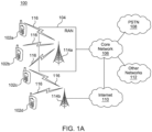
- FIG. 1A is a diagram illustrating an example communications system 100 in which one or more disclosed embodiments may be implemented.
- the communications system 100 may be a multiple access system that provides content, such as voice, data, video, messaging, broadcast, etc., to multiple wireless users.
- the communications system 100 may enable multiple wireless users to access such content through the sharing of system resources, including wireless bandwidth.
- the communications systems 100 may employ one or more channel access methods, such as code division multiple access (CDMA), time division multiple access (TDMA), frequency division multiple access (FDMA), orthogonal FDMA (OFDMA), single-carrier FDMA (SC-FDMA), zero-tail unique-word DFT-Spread OFDM (ZT UW DTS-s OFDM), unique word OFDM (UW-OFDM), resource block-filtered OFDM, filter bank multicarrier (FBMC), and the like.
- CDMA code division multiple access
- TDMA time division multiple access
- FDMA frequency division multiple access
- OFDMA orthogonal FDMA
- SC-FDMA single-carrier FDMA
- ZT UW DTS-s OFDM zero-tail unique-word DFT-Spread OFDM
- UW-OFDM unique word OFDM
- FBMC filter bank multicarrier
- the communications system 100 may include wireless transmit/receive units (WTRUs) 102a, 102b, 102c, 102d, a RAN 104/113, a CN 106/115, a public switched telephone network (PSTN) 108, the Internet 110, and other networks 112, though it will be appreciated that the disclosed embodiments contemplate any number of WTRUs, base stations, networks, and/or network elements.
- WTRUs 102a, 102b, 102c, 102d may be any type of device configured to operate and/or communicate in a wireless environment.
- the WTRUs 102a, 102b, 102c, 102d may be configured to transmit and/or receive wireless signals and may include a user equipment (UE), a mobile station, a fixed or mobile subscriber unit, a subscription-based unit, a pager, a cellular telephone, a personal digital assistant (PDA), a smartphone, a laptop, a netbook, a personal computer, a wireless sensor, a hotspot or Mi-Fi device, an Internet of Things (IoT) device, a watch or other wearable, a head-mounted display (HMD), a vehicle, a drone, a medical device and applications (e.g., remote surgery), an industrial device and applications (e.g., a robot and/or other wireless devices operating in an industrial and/or an automated processing chain contexts), a consumer electronics device, a device operating on commercial and/or industrial wireless networks, and the like.
- UE user equipment
- PDA personal digital assistant
- smartphone a laptop
- a netbook a personal computer
- the communications systems 100 may also include a base station 114a and/or a base station 114b.
- Each of the base stations 114a, 114b may be any type of device configured to wirelessly interface with at least one of the WTRUs 102a, 102b, 102c, 102d to facilitate access to one or more communication networks, such as the CN 106/115, the Internet 110, and/or the other networks 112.
- the base stations 114a, 114b may be a base transceiver station (BTS), a Node-B, an eNode B, a Home Node B, a Home eNode B, a gNB, a NR NodeB, a site controller, an access point (AP), a wireless router, and the like. While the base stations 114a, 114b are each depicted as a single element, it will be appreciated that the base stations 114a, 114b may include any number of interconnected base stations and/or network elements.
- the base station 114a may be part of the RAN 104/113, which may also include other base stations and/or network elements (not shown), such as a base station controller (BSC), a radio network controller (RNC), relay nodes, etc.
- BSC base station controller
- RNC radio network controller
- the base station 114a and/or the base station 114b may be configured to transmit and/or receive wireless signals on one or more carrier frequencies, which may be referred to as a cell (not shown). These frequencies may be in licensed spectrum, unlicensed spectrum, or a combination of licensed and unlicensed spectrum.
- a cell may provide coverage for a wireless service to a specific geographical area that may be relatively fixed or that may change over time.
- the cell may further be divided into cell sectors. For example, the cell associated with the base station 114a may be divided into three sectors.
- the base station 114a may include three transceivers, i.e., one for each sector of the cell.
- the base station 114a may employ multiple-input multiple output (MIMO) technology and may utilize multiple transceivers for each sector of the cell.
- MIMO multiple-input multiple output
- beamforming may be used to transmit and/or receive signals in desired spatial directions.
- the base stations 114a, 114b may communicate with one or more of the WTRUs 102a, 102b, 102c, 102d over an air interface 116, which may be any suitable wireless communication link (e.g., radio frequency (RF), microwave, centimeter wave, micrometer wave, infrared (IR), ultraviolet (UV), visible light, etc.).
- the air interface 116 may be established using any suitable radio access technology (RAT).
- RAT radio access technology
- the communications system 100 may be a multiple access system and may employ one or more channel access schemes, such as CDMA, TDMA, FDMA, OFDMA, SC-FDMA, and the like.
- the base station 114a in the RAN 104/113 and the WTRUs 102a, 102b, 102c may implement a radio technology such as Universal Mobile Telecommunications System (UMTS) Terrestrial Radio Access (UTRA), which may establish the air interface 115/116/117 using wideband CDMA (WCDMA).
- WCDMA may include communication protocols such as High-Speed Packet Access (HSPA) and/or Evolved HSPA (HSPA+).
- HSPA may include High-Speed Downlink (DL) Packet Access (HSDPA) and/or High-Speed UL Packet Access (HSUPA).
- the base station 114a and the WTRUs 102a, 102b, 102c may implement a radio technology such as Evolved UMTS Terrestrial Radio Access (E-UTRA), which may establish the air interface 116 using Long Term Evolution (LTE) and/or LTE-Advanced (LTE-A) and/or LTE-Advanced Pro (LTE-A Pro).
- E-UTRA Evolved UMTS Terrestrial Radio Access
- LTE Long Term Evolution
- LTE-A LTE-Advanced
- LTE-A Pro LTE-Advanced Pro
- the base station 114a and the WTRUs 102a, 102b, 102c may implement a radio technology such as NR Radio Access , which may establish the air interface 116 using New Radio (NR).
- a radio technology such as NR Radio Access , which may establish the air interface 116 using New Radio (NR).
- the base station 114a and the WTRUs 102a, 102b, 102c may implement multiple radio access technologies.
- the base station 114a and the WTRUs 102a, 102b, 102c may implement LTE radio access and NR radio access together, for instance using dual connectivity (DC) principles.
- DC dual connectivity
- the air interface utilized by WTRUs 102a, 102b, 102c may be characterized by multiple types of radio access technologies and/or transmissions sent to/from multiple types of base stations (e.g., a eNB and a gNB).
- the base station 114a and the WTRUs 102a, 102b, 102c may implement radio technologies such as IEEE 802.11 (i.e., Wireless Fidelity (WiFi), IEEE 802.16 (i.e., Worldwide Interoperability for Microwave Access (WiMAX)), CDMA2000, CDMA2000 1X, CDMA2000 EV-DO, Interim Standard 2000 (IS-2000), Interim Standard 95 (IS-95), Interim Standard 856 (IS-856), Global System for Mobile communications (GSM), Enhanced Data rates for GSM Evolution (EDGE), GSM EDGE (GERAN), and the like.
- IEEE 802.11 i.e., Wireless Fidelity (WiFi)
- IEEE 802.16 i.e., Worldwide Interoperability for Microwave Access (WiMAX)
- CDMA2000, CDMA2000 1X, CDMA2000 EV-DO Code Division Multiple Access 2000
- IS-95 Interim Standard 95
- IS-856 Interim Standard 856
- GSM Global System for
- the base station 114b in FIG. 1A may be a wireless router, Home Node B, Home eNode B, or access point, for example, and may utilize any suitable RAT for facilitating wireless connectivity in a localized area, such as a place of business, a home, a vehicle, a campus, an industrial facility, an air corridor (e.g., for use by drones), a roadway, and the like.
- the base station 114b and the WTRUs 102c, 102d may implement a radio technology such as IEEE 802.11 to establish a wireless local area network (WLAN).
- WLAN wireless local area network
- the base station 114b and the WTRUs 102c, 102d may implement a radio technology such as IEEE 802.15 to establish a wireless personal area network (WPAN).
- the base station 114b and the WTRUs 102c, 102d may utilize a cellular-based RAT (e.g., WCDMA, CDMA2000, GSM, LTE, LTE-A, LTE-A Pro, NR etc.) to establish a picocell or femtocell.
- the base station 114b may have a direct connection to the Internet 110.
- the base station 114b may not be required to access the Internet 110 via the CN 106/115.
- the RAN 104/113 may be in communication with the CN 106/115, which may be any type of network configured to provide voice, data, applications, and/or voice over internet protocol (VoIP) services to one or more of the WTRUs 102a, 102b, 102c, 102d.
- the data may have varying quality of service (QoS) requirements, such as differing throughput requirements, latency requirements, error tolerance requirements, reliability requirements, data throughput requirements, mobility requirements, and the like.
- QoS quality of service
- the CN 106/115 may provide call control, billing services, mobile location-based services, pre-paid calling, Internet connectivity, video distribution, etc., and/or perform high-level security functions, such as user authentication.
- the RAN 104/113 and/or the CN 106/115 may be in direct or indirect communication with other RANs that employ the same RAT as the RAN 104/113 or a different RAT.
- the CN 106/115 may also be in communication with another RAN (not shown) employing a GSM, UMTS, CDMA 2000, WiMAX, E-UTRA, or WiFi radio technology.
- the CN 106/115 may also serve as a gateway for the WTRUs 102a, 102b, 102c, 102d to access the PSTN 108, the Internet 110, and/or the other networks 112.
- the PSTN 108 may include circuit-switched telephone networks that provide plain old telephone service (POTS).
- POTS plain old telephone service
- the Internet 110 may include a global system of interconnected computer networks and devices that use common communication protocols, such as the transmission control protocol (TCP), user datagram protocol (UDP) and/or the internet protocol (IP) in the TCP/IP internet protocol suite.
- the networks 112 may include wired and/or wireless communications networks owned and/or operated by other service providers.
- the networks 112 may include another CN connected to one or more RANs, which may employ the same RAT as the RAN 104/113 or a different RAT.
- the WTRUs 102a, 102b, 102c, 102d in the communications system 100 may include multi-mode capabilities (e.g., the WTRUs 102a, 102b, 102c, 102d may include multiple transceivers for communicating with different wireless networks over different wireless links).
- the WTRU 102c shown in FIG. 1A may be configured to communicate with the base station 114a, which may employ a cellular-based radio technology, and with the base station 114b, which may employ an IEEE 802 radio technology.
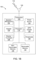
- FIG. 1B is a system diagram illustrating an example WTRU 102.
- the WTRU 102 may include a processor 118, a transceiver 120, a transmit/receive element 122, a speaker/microphone 124, a keypad 126, a display/touchpad 128, non-removable memory 130, removable memory 132, a power source 134, a global positioning system (GPS) chipset 136, and/or other peripherals 138, among others.
- GPS global positioning system
- the processor 118 may be a general purpose processor, a special purpose processor, a conventional processor, a digital signal processor (DSP), a plurality of microprocessors, one or more microprocessors in association with a DSP core, a controller, a microcontroller, Application Specific Integrated Circuits (ASICs), Field Programmable Gate Arrays (FPGAs) circuits, any other type of integrated circuit (IC), a state machine, and the like.
- the processor 118 may perform signal coding, data processing, power control, input/output processing, and/or any other functionality that enables the WTRU 102 to operate in a wireless environment.
- the processor 118 may be coupled to the transceiver 120, which may be coupled to the transmit/receive element 122. While FIG. 1B depicts the processor 118 and the transceiver 120 as separate components, it will be appreciated that the processor 118 and the transceiver 120 may be integrated together in an electronic package or chip.
- the transmit/receive element 122 may be configured to transmit signals to, or receive signals from, a base station (e.g., the base station 114a) over the air interface 116.
- a base station e.g., the base station 114a
- the transmit/receive element 122 may be an antenna configured to transmit and/or receive RF signals.
- the transmit/receive element 122 may be an emitter/detector configured to transmit and/or receive IR, UV, or visible light signals, for example.
- the transmit/receive element 122 may be configured to transmit and/or receive both RF and light signals. It will be appreciated that the transmit/receive element 122 may be configured to transmit and/or receive any combination of wireless signals.
- the WTRU 102 may include any number of transmit/receive elements 122. More specifically, the WTRU 102 may employ MIMO technology. Thus, in one embodiment, the WTRU 102 may include two or more transmit/receive elements 122 (e.g., multiple antennas) for transmitting and receiving wireless signals over the air interface 116.
- the transceiver 120 may be configured to modulate the signals that are to be transmitted by the transmit/receive element 122 and to demodulate the signals that are received by the transmit/receive element 122.
- the WTRU 102 may have multi-mode capabilities.
- the transceiver 120 may include multiple transceivers for enabling the WTRU 102 to communicate via multiple RATs, such as NR and IEEE 802.11, for example.
- the processor 118 of the WTRU 102 may be coupled to, and may receive user input data from, the speaker/microphone 124, the keypad 126, and/or the display/touchpad 128 (e.g., a liquid crystal display (LCD) display unit or organic light-emitting diode (OLED) display unit).
- the processor 118 may also output user data to the speaker/microphone 124, the keypad 126, and/or the display/touchpad 128.
- the processor 118 may access information from, and store data in, any type of suitable memory, such as the non-removable memory 130 and/or the removable memory 132.
- the non-removable memory 130 may include random-access memory (RAM), read-only memory (ROM), a hard disk, or any other type of memory storage device.
- the removable memory 132 may include a subscriber identity module (SIM) card, a memory stick, a secure digital (SD) memory card, and the like.
- SIM subscriber identity module
- SD secure digital
- the processor 118 may access information from, and store data in, memory that is not physically located on the WTRU 102, such as on a server or a home computer (not shown).
- the processor 118 may receive power from the power source 134, and may be configured to distribute and/or control the power to the other components in the WTRU 102.
- the power source 134 may be any suitable device for powering the WTRU 102.
- the power source 134 may include one or more dry cell batteries (e.g., nickel-cadmium (NiCd), nickel-zinc (NiZn), nickel metal hydride (NiMH), lithium-ion (Li-ion), etc.), solar cells, fuel cells, and the like.
- the processor 118 may further be coupled to other peripherals 138, which may include one or more software and/or hardware modules that provide additional features, functionality and/or wired or wireless connectivity.
- the peripherals 138 may include an accelerometer, an e-compass, a satellite transceiver, a digital camera (for photographs and/or video), a universal serial bus (USB) port, a vibration device, a television transceiver, a hands free headset, a Bluetooth ® module, a frequency modulated (FM) radio unit, a digital music player, a media player, a video game player module, an Internet browser, a Virtual Reality and/or Augmented Reality (VR/AR) device, an activity tracker, and the like.
- FM frequency modulated
- the peripherals 138 may include one or more sensors, the sensors may be one or more of a gyroscope, an accelerometer, a hall effect sensor, a magnetometer, an orientation sensor, a proximity sensor, a temperature sensor, a time sensor; a geolocation sensor; an altimeter, a light sensor, a touch sensor, a magnetometer, a barometer, a gesture sensor, a biometric sensor, and/or a humidity sensor.
- a gyroscope an accelerometer, a hall effect sensor, a magnetometer, an orientation sensor, a proximity sensor, a temperature sensor, a time sensor; a geolocation sensor; an altimeter, a light sensor, a touch sensor, a magnetometer, a barometer, a gesture sensor, a biometric sensor, and/or a humidity sensor.
- the WRTU 102 may include a half-duplex radio for which transmission and reception of some or all of the signals (e.g., associated with particular subframes for either the UL (e.g., for transmission) or the downlink (e.g., for reception)).
- a half-duplex radio for which transmission and reception of some or all of the signals (e.g., associated with particular subframes for either the UL (e.g., for transmission) or the downlink (e.g., for reception)).
- FIG. 1C is a system diagram illustrating the RAN 104 and the CN 106 according to an embodiment.
- the RAN 104 may employ an E-UTRA radio technology to communicate with the WTRUs 102a, 102b, 102c over the air interface 116.
- the RAN 104 may also be in communication with the CN 106.
- the RAN 104 may include eNode-Bs 160a, 160b, 160c, though it will be appreciated that the RAN 104 may include any number of eNode-Bs while remaining consistent with an embodiment.
- the eNode-Bs 160a, 160b, 160c may each include one or more transceivers for communicating with the WTRUs 102a, 102b, 102c over the air interface 116.
- the eNode-Bs 160a, 160b, 160c may implement MIMO technology.
- the eNode-B 160a for example, may use multiple antennas to transmit wireless signals to, and/or receive wireless signals from, the WTRU 102a.
- Each of the eNode-Bs 160a, 160b, 160c may be associated with a particular cell (not shown) and may be configured to handle radio resource management decisions, handover decisions, scheduling of users in the UL and/or DL, and the like. As shown in FIG. 1C , the eNode-Bs 160a, 160b, 160c may communicate with one another over an X2 interface.
- the CN 106 shown in FIG. 1C may include a mobility management entity (MME) 162, a serving gateway (SGW) 164, and a packet data network (PDN) gateway (or PGW) 166. While each of the foregoing elements are depicted as part of the CN 106, it will be appreciated that any of these elements may be owned and/or operated by an entity other than the CN operator.
- MME mobility management entity
- SGW serving gateway
- PGW packet data network gateway
- the MME 162 may be connected to each of the eNode-Bs 162a, 162b, 162c in the RAN 104 via an S1 interface and may serve as a control node.
- the MME 162 may be responsible for authenticating users of the WTRUs 102a, 102b, 102c, bearer activation/deactivation, selecting a particular serving gateway during an initial attach of the WTRUs 102a, 102b, 102c, and the like.
- the MME 162 may provide a control plane function for switching between the RAN 104 and other RANs (not shown) that employ other radio technologies, such as GSM and/or WCDMA.
- the SGW 164 may be connected to each of the eNode Bs 160a, 160b, 160c in the RAN 104 via the S1 interface.
- the SGW 164 may generally route and forward user data packets to/from the WTRUs 102a, 102b, 102c.
- the SGW 164 may perform other functions, such as anchoring user planes during inter-eNode B handovers, triggering paging when DL data is available for the WTRUs 102a, 102b, 102c, managing and storing contexts of the WTRUs 102a, 102b, 102c, and the like.
- the SGW 164 may be connected to the PGW 166, which may provide the WTRUs 102a, 102b, 102c with access to packet-switched networks, such as the Internet 110, to facilitate communications between the WTRUs 102a, 102b, 102c and IP-enabled devices.
- packet-switched networks such as the Internet 110
- the CN 106 may facilitate communications with other networks.
- the CN 106 may provide the WTRUs 102a, 102b, 102c with access to circuit-switched networks, such as the PSTN 108, to facilitate communications between the WTRUs 102a, 102b, 102c and traditional land-line communications devices.
- the CN 106 may include, or may communicate with, an IP gateway (e.g., an IP multimedia subsystem (IMS) server) that serves as an interface between the CN 106 and the PSTN 108.
- IMS IP multimedia subsystem
- the CN 106 may provide the WTRUs 102a, 102b, 102c with access to the other networks 112, which may include other wired and/or wireless networks that are owned and/or operated by other service providers.
- the WTRU is described in FIGS. 1A-1D as a wireless terminal, it is contemplated that in certain representative embodiments that such a terminal may use (e.g., temporarily or permanently) wired communication interfaces with the communication network.
- a WLAN in Infrastructure Basic Service Set (BSS) mode may have an Access Point (AP) for the BSS and one or more stations (STAs) associated with the AP.
- the AP may have an access or an interface to a Distribution System (DS) or another type of wired/wireless network that carries traffic in to and/or out of the BSS.
- Traffic to STAs that originates from outside the BSS may arrive through the AP and may be delivered to the STAs.
- Traffic originating from STAs to destinations outside the BSS may be sent to the AP to be delivered to respective destinations.
- Traffic between STAs within the BSS may be sent through the AP, for example, where the source STA may send traffic to the AP and the AP may deliver the traffic to the destination STA.
- the traffic between STAs within a BSS may be considered and/or referred to as peer-to-peer traffic.
- the peer-to-peer traffic may be sent between (e.g., directly between) the source and destination STAs with a direct link setup (DLS).
- the DLS may use an 802.11e DLS or an 802.11z tunneled DLS (TDLS).
- a WLAN using an Independent BSS (IBSS) mode may not have an AP, and the STAs (e.g., all of the STAs) within or using the IBSS may communicate directly with each other.
- the IBSS mode of communication may sometimes be referred to herein as an "ad-hoc" mode of communication.
- the AP may transmit a beacon on a fixed channel, such as a primary channel.
- the primary channel may be a fixed width (e.g., 20 MHz wide bandwidth) or a dynamically set width via signaling.
- the primary channel may be the operating channel of the BSS and may be used by the STAs to establish a connection with the AP.
- Carrier Sense Multiple Access with Collision Avoidance (CSMA/CA) may be implemented, for example in in 802.11 systems.
- the STAs e.g., every STA, including the AP, may sense the primary channel. If the primary channel is sensed/detected and/or determined to be busy by a particular STA, the particular STA may back off.
- One STA (e.g., only one station) may transmit at any given time in a given BSS.
- HT STAs may use a 40 MHz wide channel for communication, for example, via a combination of the primary 20 MHz channel with an adjacent or nonadjacent 20 MHz channel to form a 40 MHz wide channel.
- VHT STAs may support 20MHz, 40 MHz, 80 MHz, and/or 160 MHz wide channels.
- the 40 MHz, and/or 80 MHz, channels may be formed by combining contiguous 20 MHz channels.
- a 160 MHz channel may be formed by combining 8 contiguous 20 MHz channels, or by combining two non-contiguous 80 MHz channels, which may be referred to as an 80+80 configuration.
- the data, after channel encoding may be passed through a segment parser that may divide the data into two streams.
- Inverse Fast Fourier Transform (IFFT) processing, and time domain processing may be done on each stream separately.
- IFFT Inverse Fast Fourier Transform
- the streams may be mapped on to the two 80 MHz channels, and the data may be transmitted by a transmitting STA.
- the above described operation for the 80+80 configuration may be reversed, and the combined data may be sent to the Medium Access Control (MAC).
- MAC Medium Access Control
- Sub 1 GHz modes of operation are supported by 802.11af and 802.11ah.
- the channel operating bandwidths, and carriers, are reduced in 802.11af and 802.11ah relative to those used in 802.11n, and 802.11ac.
- 802.11af supports 5 MHz, 10 MHz and 20 MHz bandwidths in the TV White Space (TVWS) spectrum
- 802.11ah supports 1 MHz, 2 MHz, 4 MHz, 8 MHz, and 16 MHz bandwidths using non-TVWS spectrum.
- 802.11ah may support Meter Type Control/Machine-Type Communications, such as MTC devices in a macro coverage area.
- MTC devices may have certain capabilities, for example, limited capabilities including support for (e.g., only support for) certain and/or limited bandwidths.
- the MTC devices may include a battery with a battery life above a threshold (e.g., to maintain a very long battery life).
- WLAN systems which may support multiple channels, and channel bandwidths, such as 802.11n, 802.11ac, 802.11af, and 802.11ah, include a channel which may be designated as the primary channel.
- the primary channel may have a bandwidth equal to the largest common operating bandwidth supported by all STAs in the BSS.
- the bandwidth of the primary channel may be set and/or limited by a STA, from among all STAs in operating in a BSS, which supports the smallest bandwidth operating mode.
- the primary channel may be 1 MHz wide for STAs (e.g., MTC type devices) that support (e.g., only support) a 1 MHz mode, even if the AP, and other STAs in the BSS support 2 MHz, 4 MHz, 8 MHz, 16 MHz, and/or other channel bandwidth operating modes.
- Carrier sensing and/or Network Allocation Vector (NAV) settings may depend on the status of the primary channel. If the primary channel is busy, for example, due to a STA (which supports only a 1 MHz operating mode), transmitting to the AP, the entire available frequency bands may be considered busy even though a majority of the frequency bands remains idle and may be available.
- STAs e.g., MTC type devices
- NAV Network Allocation Vector
- the available frequency bands which may be used by 802.11ah, are from 902 MHz to 928 MHz. In Korea, the available frequency bands are from 917.5 MHz to 923.5 MHz. In Japan, the available frequency bands are from 916.5 MHz to 927.5 MHz. The total bandwidth available for 802.11ah is 6 MHz to 26 MHz depending on the country code.
- FIG. 1D is a system diagram illustrating the RAN 113 and the CN 115 according to an embodiment.
- the RAN 113 may employ an NR radio technology to communicate with the WTRUs 102a, 102b, 102c over the air interface 116.
- the RAN 113 may also be in communication with the CN 115.
- the RAN 113 may include gNBs 180a, 180b, 180c, though it will be appreciated that the RAN 113 may include any number of gNBs while remaining consistent with an embodiment.
- the gNBs 180a, 180b, 180c may each include one or more transceivers for communicating with the WTRUs 102a, 102b, 102c over the air interface 116.
- the gNBs 180a, 180b, 180c may implement MIMO technology.
- gNBs 180a, 108b may utilize beamforming to transmit signals to and/or receive signals from the gNBs 180a, 180b, 180c.
- the gNB 180a may use multiple antennas to transmit wireless signals to, and/or receive wireless signals from, the WTRU 102a.
- the gNBs 180a, 180b, 180c may implement carrier aggregation technology.
- the gNB 180a may transmit multiple component carriers to the WTRU 102a (not shown). A subset of these component carriers may be on unlicensed spectrum while the remaining component carriers may be on licensed spectrum.
- the gNBs 180a, 180b, 180c may implement Coordinated Multi-Point (CoMP) technology.
- WTRU 102a may receive coordinated transmissions from gNB 180a and gNB 180b (and/or gNB 180c).
- CoMP Coordinated Multi-Point
- the WTRUs 102a, 102b, 102c may communicate with gNBs 180a, 180b, 180c using transmissions associated with a scalable numerology. For example, the OFDM symbol spacing and/or OFDM subcarrier spacing may vary for different transmissions, different cells, and/or different portions of the wireless transmission spectrum.
- the WTRUs 102a, 102b, 102c may communicate with gNBs 180a, 180b, 180c using subframe or transmission time intervals (TTIs) of various or scalable lengths (e.g., containing varying number of OFDM symbols and/or lasting varying lengths of absolute time).
- TTIs subframe or transmission time intervals
- the gNBs 180a, 180b, 180c may be configured to communicate with the WTRUs 102a, 102b, 102c in a standalone configuration and/or a non-standalone configuration.
- WTRUs 102a, 102b, 102c may communicate with gNBs 180a, 180b, 180c without also accessing other RANs (e.g., such as eNode-Bs 160a, 160b, 160c).
- WTRUs 102a, 102b, 102c may utilize one or more of gNBs 180a, 180b, 180c as a mobility anchor point.
- WTRUs 102a, 102b, 102c may communicate with gNBs 180a, 180b, 180c using signals in an unlicensed band.
- WTRUs 102a, 102b, 102c may communicate with/connect to gNBs 180a, 180b, 180c while also communicating with/connecting to another RAN such as eNode-Bs 160a, 160b, 160c.
- WTRUs 102a, 102b, 102c may implement DC principles to communicate with one or more gNBs 180a, 180b, 180c and one or more eNode-Bs 160a, 160b, 160c substantially simultaneously.
- eNode-Bs 160a, 160b, 160c may serve as a mobility anchor for WTRUs 102a, 102b, 102c and gNBs 180a, 180b, 180c may provide additional coverage and/or throughput for servicing WTRUs 102a, 102b, 102c.
- Each of the gNBs 180a, 180b, 180c may be associated with a particular cell (not shown) and may be configured to handle radio resource management decisions, handover decisions, scheduling of users in the UL and/or DL, support of network slicing, dual connectivity, interworking between NR and E-UTRA, routing of user plane data towards User Plane Function (UPF) 184a, 184b, routing of control plane information towards Access and Mobility Management Function (AMF) 182a, 182b and the like. As shown in FIG. 1D , the gNBs 180a, 180b, 180c may communicate with one another over an Xn interface.
- UPF User Plane Function
- AMF Access and Mobility Management Function
- the CN 115 shown in FIG. 1D may include at least one AMF 182a, 182b, at least one UPF 184a,184b, at least one Session Management Function (SMF) 183a, 183b, and possibly a Data Network (DN) 185a, 185b. While each of the foregoing elements are depicted as part of the CN 115, it will be appreciated that any of these elements may be owned and/or operated by an entity other than the CN operator.
- AMF Session Management Function
- the AMF 182a, 182b may be connected to one or more of the gNBs 180a, 180b, 180c in the RAN 113 via an N2 interface and may serve as a control node.
- the AMF 182a, 182b may be responsible for authenticating users of the WTRUs 102a, 102b, 102c, support for network slicing (e.g., handling of different PDU sessions with different requirements), selecting a particular SMF 183a, 183b, management of the registration area, termination of NAS signaling, mobility management, and the like.
- Network slicing may be used by the AMF 182a, 182b in order to customize CN support for WTRUs 102a, 102b, 102c based on the types of services being utilized WTRUs 102a, 102b, 102c.
- different network slices may be established for different use cases such as services relying on ultra-reliable low latency (URLLC) access, services relying on enhanced massive mobile broadband (eMBB) access, services for machine type communication (MTC) access, and/or the like.
- URLLC ultra-reliable low latency
- eMBB enhanced massive mobile broadband
- MTC machine type communication
- the AMF 162 may provide a control plane function for switching between the RAN 113 and other RANs (not shown) that employ other radio technologies, such as LTE, LTE-A, LTE-A Pro, and/or non-3GPP access technologies such as WiFi.
- radio technologies such as LTE, LTE-A, LTE-A Pro, and/or non-3GPP access technologies such as WiFi.
- the SMF 183a, 183b may be connected to an AMF 182a, 182b in the CN 115 via an N11 interface.
- the SMF 183a, 183b may also be connected to a UPF 184a, 184b in the CN 115 via an N4 interface.
- the SMF 183a, 183b may select and control the UPF 184a, 184b and configure the routing of traffic through the UPF 184a, 184b.
- the SMF 183a, 183b may perform other functions, such as managing and allocating UE IP address, managing PDU sessions, controlling policy enforcement and QoS, providing downlink data notifications, and the like.
- a PDU session type may be IP-based, non-IP based, Ethernet-based, and the like.
- the UPF 184a, 184b may be connected to one or more of the gNBs 180a, 180b, 180c in the RAN 113 via an N3 interface, which may provide the WTRUs 102a, 102b, 102c with access to packet-switched networks, such as the Internet 110, to facilitate communications between the WTRUs 102a, 102b, 102c and IP-enabled devices.
- the UPF 184, 184b may perform other functions, such as routing and forwarding packets, enforcing user plane policies, supporting multi-homed PDU sessions, handling user plane QoS, buffering downlink packets, providing mobility anchoring, and the like.
- the CN 115 may facilitate communications with other networks.
- the CN 115 may include, or may communicate with, an IP gateway (e.g., an IP multimedia subsystem (IMS) server) that serves as an interface between the CN 115 and the PSTN 108.
- IP gateway e.g., an IP multimedia subsystem (IMS) server
- IMS IP multimedia subsystem
- the CN 115 may provide the WTRUs 102a, 102b, 102c with access to the other networks 112, which may include other wired and/or wireless networks that are owned and/or operated by other service providers.
- the WTRUs 102a, 102b, 102c may be connected to a local Data Network (DN) 185a, 185b through the UPF 184a, 184b via the N3 interface to the UPF 184a, 184b and an N6 interface between the UPF 184a, 184b and the DN 185a, 185b.
- DN local Data Network
- one or more, or all, of the functions described herein with regard to one or more of: WTRU 102a-d, Base Station 114a-b, eNode-B 160a-c, MME 162, SGW 164, PGW 166, gNB 180a-c, AMF 182a-ab, UPF 184a-b, SMF 183a-b, DN 185a-b, and/or any other device(s) described herein, may be performed by one or more emulation devices (not shown).
- the emulation devices may be one or more devices configured to emulate one or more, or all, of the functions described herein.
- the emulation devices may be used to test other devices and/or to simulate network and/or WTRU functions.
- the emulation devices may be designed to implement one or more tests of other devices in a lab environment and/or in an operator network environment.
- the one or more emulation devices may perform the one or more, or all, functions while being fully or partially implemented and/or deployed as part of a wired and/or wireless communication network in order to test other devices within the communication network.
- the one or more emulation devices may perform the one or more, or all, functions while being temporarily implemented/deployed as part of a wired and/or wireless communication network.
- the emulation device may be directly coupled to another device for purposes of testing and/or may performing testing using over-the-air wireless communications.
- the one or more emulation devices may perform the one or more, including all, functions while not being implemented/deployed as part of a wired and/or wireless communication network.
- the emulation devices may be utilized in a testing scenario in a testing laboratory and/or a non-deployed (e.g., testing) wired and/or wireless communication network in order to implement testing of one or more components.
- the one or more emulation devices may be test equipment. Direct RF coupling and/or wireless communications via RF circuitry (e.g., which may include one or more antennas) may be used by the emulation devices to transmit and/or receive data.
- RF circuitry e.g., which may include one or more antennas
- Communication in a RAN may be carried out according to a number of protocols. These protocols may be categorized into a number of layers, such as packet data convergence protocol (PDCP), Radio-link Control (RLC), Medium-access control (MAC), and a Physical layer (PHY). These layers may exist and have reciprocal functions in both a transmitting entity and a receiving entity.
- a transmitting entity may be a base station, such as a gNB, and a receiving entity, such as a WTRU, or these roles may be reversed.
- PHY layer channel coding/decoding, modulation/demodulation, multi-antenna mapping, and other related functions may be handled.
- Polar Codes may be used because they present favorable results in encoding and decoding in addition to code construction when compared with other approaches.
- Polar Code construction for Polar Codes may require calculating reliabilities of input bits and selecting frozen and unfrozen bits by sorting their reliabilities.
- a given code construction procedure may assume some specific conditions of channel characteristics and the final code construction may be changed if the channel characteristics, including the specific conditions, change.
- rate-matching may be based on a puncturing scheme such as Quasi-Uniform Puncturing (QUP) where output bits may be punctured by a pattern of bit reversal that starts from the beginning.
- QUP shows good performance but code reconstruction is needed for every unique puncturing number. This means that the positions of frozen bits may be different for each additional puncturing bit.
- Code reconstruction of polar codes may require a large computational load if frequent rate matching needs to be applied for a coded block.
- the decoder may assume that the corresponding input bits (gradually decreased index from the end) are set to 0 for calculating a log likelihood (LL).
- LL log likelihood
- Polar Code specific HARQ schemes may be employed to take advantage of the benefits of a Polar Code approach.
- a rate-matching scheme may be combined with any type of channel coding and modulation scheme, but performance improvements may be seen when using a Polar Code specific scheme, such as those discussed herein.
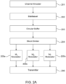
- FIG. 2A illustrates a non-exhaustive configuration of components used to implement one or more rate-matching embodiments for a transmitter.
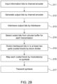
- FIG. 2B illustrates an example procedure for rate-matching according to one or more embodiments for a transmitter.
- FIG. 2A and 2B will be discussed in conjunction with one another.
- K information bits are encoded 212 by the channel encoder 201 resulting in N output bits, also known as a coded stream (e.g., codeword).
- the N output bits are processed at an interleaver 202.
- the selected coded stream from the circular buffer 203 is then divided 215 into at least two parts, each part also known as a coded block, by a block divider 204.
- the constant modulation for each block may result in a simple implementation for managing operations for a filter and/or power amp in the transmitter.
- the structure of the interleaver and the block divider may minimize required buffers to decode the received symbols at a receiver side during a HARQ processes.
- each part i.e., coded block
- modulator 205a, 205b, ...205n collectively known as modulator 205.
- the modulated bits also known as symbols, may be transmitted 217 by a transmitter 206.
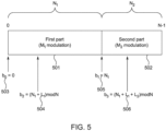
- FIG. 2C illustrates an example where the N bit coded stream is divided into two parts of a first part 221 with M 1 modulation and a second part 222 with M 2 modulation.
- any of the embodiments discussed herein may not be restricted to two parts and may have any number of parts as explained with reference to FIG. 2A and 2B .
- a rate-matching scheme may assume a single modulation scheme ( M 1 -ary modulation) during one transmission time interval (TTI) where N m 1 is representative of the number of modulation symbols for the whole coded bit stream, (i.e, codeword). If P bits are punctured from the output bits, the number of modulation symbols is reduced to N ⁇ P m 1 where [x] is the minimum integer larger than x .
- N 2 m 2 m 2 ⁇ m 1 P consecutive bits mapped as M 2 -ary symbols
- N 1 N ⁇ m 2 m 2 ⁇ m 1 P consecutive bits are mapped as M 1 -ary symbols.
- BPSK Binary Phase Shift Keying
- QPSK Quadrature Phase Shift Keying
- the total number of modulation symbols is 896 symbols and it has the same number of symbols when 128 bits are punctured and BPSK is adopted as the modulation scheme for all punctured bits.
- different modulation techniques may be used such as any type of phase-shift keying (PSK), frequency-shift keying (FSK), amplitude-shift keying (ASK), and/or quadrature amplitude modulation (QAM).
- PSK phase-shift keying
- FSK frequency-shift keying
- ASK amplitude-shift keying
- QAM quadrature amplitude modulation
- a reconstruction process of encoding at the codeword parts may not be required, hence the position of frozen bits may be kept the same. This outcome may provide a significant reduction in encoding computation in case of rate matching for polar codes.
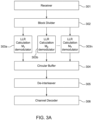
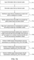
- FIG. 3A illustrates a non-exhaustive configuration of components used to implement one or more rate-matching embodiments for a receiver.
- FIG. 3B illustrates an example procedure for rate-matching for a receiver according to one or more embodiments.
- FIG. 3A and 3B will be discussed in conjunction with one another.
- symbols may be received at a receiver 301 from a channel.
- the received symbols may then be divided 312 into two parts at a block divider 302.
- a log likelihood ratio (LLR) values or LL values may be computed 313 by a demodulator (or demapper) for each part 303a, 303b, ... 303n, where n is the number of parts.
- LLR log likelihood ratio
- the LLR or LL calculation method may be different.
- the transmitter may have sent the modulation indices to the receiver along with the other decoding related information to be used at the receiver.
- the parts are combined 314 with other bits in the circular buffer 304 and then de-interleaved 315 by a de-interleaver 305 based on the interleaving pattern of the transmitter side.
- the de-interleaved parts are input to a channel decoder 306 to be decoded 316 and the original information bits are output from the channel decoder 306 for processing 317.
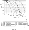
- FIG. 4 shows a Block Error Rate (BLER) test of the rate-matching techniques and embodiments disclosed herein compared to an alternative puncturing scheme with polar code encoding.
- the horizontal axis shows a normalized signal to noise ration E s /N 0 401.
- the vertical axis shows the BLER 402 ratio that is defined by the number of erroneous blocks received to the total number of blocks sent (an erroneous block being a transport block that has different decoded bit(s) from the information bits sent by the transmitter).
- the rate-matching techniques and embodiments disclosed herein are indicated by the designation irregular modulation scheme.
- results comprise examples of a 4/7 coding rate with an irregular modulation scheme at 404, a 2/3 coding rate with the irregular modulation scheme at 406, and a 4/5 coding rate with an irregular modulation scheme at 408.
- the disclosed techniques and embodiments have coding gains of 0.3 dB, 0.6 dB and 1.3 dB over the alternative puncturing scheme at a BLER of 10 -3 while having the same spectral efficiency.
- a HARQ procedure may involve a retransmission technique that is based on the rate matching block as discussed herein.
- the bit position may be defined as bit index 0 ⁇ N-1 for bits after channel coding and interleaving.
- Some of the parameters used for describing this HARQ scheme are: b i may represent a starting bit index of an i-th retransmission; L i may represent a length of an i-th retransmission; and c i may represent an offset value of an i-th retransmission.
- b 1 may be set to N 1 + c 1 , without a loss of generality, and the second transmission in HARQ may start from the same starting bit index of M 2 -ary modulation.
- the values of L i may be determined by a base station, or other such node, depending on an established link adaptation scheme and this information may be sent to the receiver via corresponding control channel information.
- the base station may select a modulation and coding scheme (MCS) level for downlink and/or uplink transmission according to measurement information or adaptation strategy, and L i may be calculated based on the base station's scheduling algorithm.
- MCS modulation and coding scheme
- the received symbols in the retransmissions may not be divided in the block divider in FIG. 2B differently from the first transmission.
- the proper positions for LLR or LL values in a circular buffer may be selected in a bit selection block and they may be stored or combined with the conventional values in the positions of the circular buffer for HARQ operation.
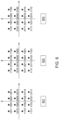
- FIG. 6 shows an example of an LTE QAM constellation and effective constellations when offset according to the embodiments disclosed herein.
- the QAM constellation shown in 601 When the QAM constellation shown in 601 is applied in the first transmission, some coding gain may be achieved in the first retransmission (the second transmission) by setting c 1 to 2.
- Four bits indicate a QAM symbol and the reliability of each bit position is different in 601. Where “abcd” indicates a QAM symbol, and "ab” has larger reliability than "cd”, then there may be some coding gain by combining less reliable bit(s) in the first transmission with more reliable bit(s) in the first retransmission (the second transmission).
- c i may be set to maximize a coding gain.
- a different modulation mapping may be used to improve gains of each retransmission.
- a bit reversed mapping as shown in 603 may be used in the first retransmission (the second transmission).
- the effective code rate R i of for each transmission may be derived as shown in Equation 2.
- the effective spectral efficiency S i of the disclosed HARQ scheme for each transmission may be derived as shown in Equation 3.
- m i r is the modulation order adopted for i-th retransmission.
- the modulation order of m i r may be selected in conjunction with the puncturing number, P.
- the modulation order of each retransmission may be selected such that the overall puncturing number, P, is satisfied after all retransmissions are completed.
- the modulation series corresponding to the retransmission parts may be sent to the receiver via a control channel along with the other retransmission related information.
- FIG. 7A and 7B are an example of a HARQ scheme according to one or more techniques or embodiments as disclosed herein. Similar numbering and meaning may be taken from the elements and related description of FIG. 5 . There may be a first transmission with a first part 501 and a second part 502.
- a single constant modulation may be used as Equation 3 and multiple modulations may also be applied.
- the retransmitted bit block with length L j may be divided into multiple blocks, each with a different modulation.
- the division border in the retransmitted bit block may follow the same border as in the first transmission.
- M 1 -ary modulation may be used for the second part and M 1 -ary modulation may be used for the first part in the retransmission 702, 705.
- the decoder may have more combining gain.
- N output bits also known as coded stream (e.g., codeword)
- the generated N output bits are interleaved 713 and stored in a circular buffer.
- the coded stream is then divided 714 into at least two parts N 1 and N 2 , each part also known as a coded block, by a block divider. After the division, each part (i.e., coded block) is mapped/modulated 715 by modulators of different orders.
- m n is the n th codeword
- M n is the n-ary (e.g., primary, secondary, etc.) number modulation.
- the modulation generates symbols that are then transmitted 716 in a first transmission 701 starting at bit b 0 503 with length L 0 .
- the retransmissions may start when the receiver finds error(s) in the decoded bits and send a negative acknowledgement to the transmitter for each transmission.
- a HARQ based retransmission (fourth transmission 704) may start at bit b 3 506 with length L 3 . Note that because the fourth transmission 702 starts at bit b 3 506, which is past the beginning of the second part 502, the buffer becomes circular in nature as shown with arrow 706 and continues into the first part 501.
- This example may be similar to a "circular buffer" in one or more LTE specifications. Each transmission may be a different revision number as discussed herein.
- the starting bit index in a HARQ first retransmission may start in the starting bit index of the second part.
- the starting bit index in all retransmissions may have offsets to improve performance.
- the number of bits in each part and modulation order may be determined based on the equation described with reference to the disclosed rate matching method, which is equivalent to puncturing P bits.
- the channel coded bits that are interleaved and divided into multiple parts may use different modulations for each part.
- rv may be defined as an integer with a length of two bits that may correspond to the bit position previously defined as b i .
- the rv may be assigned by base stations, or other such nodes, and changed for each resource allocation.
- the rv may be sent to a WTRU by a control channel, such as PDCCH, or may be defined by a predetermined rule like 00 ⁇ 10 ⁇ 01 ⁇ 11.
- FIG. 8 shows an example of a BLER performance according to embodiments for a HARQ scheme when polar codes are assumed as the channel coding scheme as disclosed herein.
- the horizontal axis shows a normalized signal to noise ration E s /N 0 401.
- the vertical axis shows the BLER 402 ratio that is defined by the number of erroneous blocks received to the total number of blocks sent (an erroneous block being a transport block that has different decoded bit(s) from the information bits sent by the transmitter.).
- the disclosed HARQ scheme provides coding gains of 0.8 dB, 1.55 dB and 2.3 dB at a BLER of 10 -3 over the 1st 811 transmission from 2 nd 812, 3 rd 813, and 4 th 814 transmissions (1st, 2nd and 3rd retransmissions). In each retransmission, the incremental redundancy corresponding to the first transmission is retransmitted for HARQ operation.
- ROM read only memory
- RAM random access memory
- register cache memory
- semiconductor memory devices magnetic media such as internal hard disks and removable disks, magneto-optical media, and optical media such as CD-ROM disks, and digital versatile disks (DVDs).
- a processor in association with software may be used to implement a radio frequency transceiver for use in a WTRU, UE, terminal, base station, RNC, or any host computer.
Landscapes
- Engineering & Computer Science (AREA)
- Computer Networks & Wireless Communication (AREA)
- Signal Processing (AREA)
- Quality & Reliability (AREA)
- Mobile Radio Communication Systems (AREA)
Claims (15)
- Verfahren zur Kanalcodierung, das Verfahren umfassend:Auswählen (214) einer Vielzahl von kodierten Bits aus einem Ringpuffer;Aufteilen (215) der Vielzahl kodierter Bits aus dem Ringpuffer in einen ersten Teil (221) und einen zweiten Teil (222);Mapping (216) des ersten Teils gemäß einem ersten Modulationsschema (M1) und des zweiten Teils gemäß einem zweiten Modulationsschema (M2), wobei das zweite Modulationsschema eine zweite Modulationsordnung enthält, die größer ist als eine erste Modulationsordnung des ersten Modulationsschemas, wobei die Länge des ersten Teils (N1) und die Länge des zweiten Teils (N2) von der ersten und zweiten Modulationsordnung abhängen, undwobei die Länge des ersten Teils und die Länge des zweiten Teils ferner von einer Länge in Symbolen basierend auf dem ersten Modulationsschema abgeleitet werden, die sich aus der Punktierung der kodierten Bits unter Verwendung einer Ratenanpassungsfunktion ergibt; undÜbertragen (217) einer ersten Übertragung basierend auf dem Mapping.
- Verfahren nach Anspruch 1, wobei die Vielzahl kodierter Bits aus dem Ringpuffer für HARQ-basierte Übertragungen ausgewählt wird.
- Verfahren nach Anspruch 2, ferner umfassend das Übertragen einer zweiten Übertragung nach der ersten Übertragung, beginnend an einer Bitposition eines Endes der ersten Übertragung, wobei die zweite Übertragung eine erneute Übertragung ist.
- Verfahren nach Anspruch 2, ferner umfassend das Übertragen einer zweiten Übertragung nach der ersten Übertragung, beginnend an einem oder mehreren Bits, die von einem Ende der ersten Übertragung verschoben sind, wobei die zweite Übertragung eine Wiederholung ist.
- Verfahren nach Anspruch 1, wobei die erste Übertragung alle Bits in dem Ringpuffer enthält.
- Verfahren nach Anspruch 2, wobei die zweite Übertragung von einem zweiten Teil des Ringspeichers ausgeht.
- Verfahren nach Anspruch 3, wobei die zweite Übertragung ein oder mehrere Bits enthält, die mit zwei verschiedenen Modulationsordnungen moduliert sind.
- Vorrichtung zur Kanalcodierung, enthaltend:einen Prozessor (118), konfiguriert, eine Vielzahl von codierten Bits aus einem Ringpuffer auszuwählen und in einen ersten Teil (221) und einen zweiten Teil (222) aufzuteilen, den ersten Teil gemäß einem ersten Modulationsschema (M1) und den zweiten Teil gemäß einem zweiten Modulationsschema (M2) abzubilden,wobei das zweite Modulationsschema eine zweite Modulationsordnung aufweist, die größer als eine erste Modulationsordnung des ersten Modulationsschemas ist, wobei die Länge des ersten Teils (N1) und die Länge des zweiten Teils (N2) von der ersten und der zweiten Modulationsordnung abhängen, undwobei die Länge des ersten Teils und die Länge des zweiten Teils ferner von einer Länge in Symbolen basierend auf dem ersten Modulationsschema abgeleitet werden, die sich aus der Punktierung der kodierten Bits unter Verwendung einer Ratenanpassungsfunktion ergibt; undeinen Transceiver (120), der operativ mit dem Prozessor gekoppelt ist, wobei der Transceiver und der Prozessor konfiguriert sind, eine erste Übertragung basierend auf dem Mapping zu übertragen.
- Vorrichtung nach Anspruch 8, wobei die Vielzahl kodierter Bits aus dem Ringpuffer für HARQ-basierte Übertragungen ausgewählt wird.
- Vorrichtung nach Anspruch 9, wobei der Transceiver und der Prozessor ferner konfiguriert sind, eine zweite Übertragung nach der ersten Übertragung, beginnend an einer Bitposition eines Endes der ersten Übertragung, zu übertragen, wobei die zweite Übertragung eine erneute Übertragung ist.
- Vorrichtung nach Anspruch 9, wobei der Transceiver und der Prozessor ferner konfiguriert sind, dass sie eine zweite Übertragung nach der ersten Übertragung, beginnend an einem oder mehreren Bits, die von einem Ende der ersten Übertragung verschoben sind, zu übertragen, wobei die zweite Übertragung eine erneute Übertragung ist.
- Vorrichtung nach Anspruch 8, wobei die erste Übertragung alle Bits in dem Ringspeicher enthält.
- Vorrichtung nach Anspruch 9, wobei die zweite Übertragung von einem zweiten Teil des Ringspeichers ausgeht.
- Verfahren nach Anspruch 1, wobei die Länge des zweiten Teils auf einer Anzahl der punktierten Codebits basiert.
- Vorrichtung nach Anspruch 8, wobei die Länge des zweiten Teils auf einer Anzahl der punktierten Codebits basiert.
Applications Claiming Priority (2)
| Application Number | Priority Date | Filing Date | Title |
|---|---|---|---|
| US201662405558P | 2016-10-07 | 2016-10-07 | |
| PCT/US2017/055665 WO2018068025A1 (en) | 2016-10-07 | 2017-10-06 | Rate matching and harq with irregular modulation |
Publications (2)
| Publication Number | Publication Date |
|---|---|
| EP3523905A1 EP3523905A1 (de) | 2019-08-14 |
| EP3523905B1 true EP3523905B1 (de) | 2025-04-16 |
Family
ID=60162285
Family Applications (1)
| Application Number | Title | Priority Date | Filing Date |
|---|---|---|---|
| EP17788033.3A Active EP3523905B1 (de) | 2016-10-07 | 2017-10-06 | Ratenanpassung und harq mit unregelmässiger modulation |
Country Status (4)
| Country | Link |
|---|---|
| US (1) | US11356193B2 (de) |
| EP (1) | EP3523905B1 (de) |
| CN (1) | CN109997326B (de) |
| WO (1) | WO2018068025A1 (de) |
Families Citing this family (11)
| Publication number | Priority date | Publication date | Assignee | Title |
|---|---|---|---|---|
| US6429357B1 (en) | 1999-05-14 | 2002-08-06 | Dekalb Genetics Corp. | Rice actin 2 promoter and intron and methods for use thereof |
| US10917194B2 (en) * | 2016-11-03 | 2021-02-09 | Telefonaktiebolaget Lm Ericsson (Publ) | Systems and methods for rate-compatible polar codes for general channels |
| US10873347B2 (en) * | 2017-08-07 | 2020-12-22 | Mediatek Inc. | Channel bit interleaver design for polar coding chain |
| CN112567668B (zh) * | 2018-08-08 | 2025-01-10 | 交互数字专利控股公司 | 用于未许可波段中新无线电操作的有效且可靠的应答过程 |
| US12155480B2 (en) * | 2019-11-04 | 2024-11-26 | Qualcomm Incorporated | Interleaving transport blocks in broadcast transmissions |
| EP4175186A4 (de) | 2020-06-26 | 2024-02-07 | Samsung Electronics Co., Ltd. | Vorrichtung und verfahren zur codierung oder decodierung eines polaren codes in einem kommunikationssystem |
| CN112003676B (zh) * | 2020-08-25 | 2021-09-14 | 深圳职业技术学院 | 有效的物联网数据传输方法及系统 |
| CN112003675B (zh) * | 2020-08-25 | 2021-09-14 | 深圳职业技术学院 | 物联网中的数据传输方法及系统 |
| CN112003677B (zh) * | 2020-08-25 | 2022-03-25 | 深圳职业技术学院 | 物联网中的数据传输方法及系统 |
| CN115085862A (zh) * | 2021-03-16 | 2022-09-20 | 中兴通讯股份有限公司 | 数据传输方法、设备和存储介质 |
| US12448211B1 (en) * | 2025-04-25 | 2025-10-21 | Coupang Corp. | Managing allocation of workstations in fulfillment center |
Family Cites Families (15)
| Publication number | Priority date | Publication date | Assignee | Title |
|---|---|---|---|---|
| JP3875693B2 (ja) * | 2004-03-24 | 2007-01-31 | 株式会社東芝 | Lpc符号を用いた符号化ビットのマッピング方法及び送信装置 |
| KR20070084434A (ko) | 2004-11-24 | 2007-08-24 | 마츠시타 덴끼 산교 가부시키가이샤 | 레이트 매칭 장치, 무선 송신 장치, 무선 수신 장치 및레이트 매칭 방법 |
| US8726121B2 (en) * | 2007-03-27 | 2014-05-13 | Qualcomm Incorporated | Circular buffer based rate matching |
| CN101075857B (zh) | 2007-04-29 | 2010-05-26 | 中兴通讯股份有限公司 | 一种turbo码的块交织及HARQ包生成方法 |
| CN101119182B (zh) | 2007-08-13 | 2013-02-27 | 中兴通讯股份有限公司 | 一种高阶调制中的比特优先选择方法 |
| US7986741B2 (en) * | 2007-09-28 | 2011-07-26 | Samsung Electronics Co., Ltd. | Method and apparatus of improved circular buffer rate matching for turbo-coded MIMO-OFDM wireless systems |
| WO2009057922A1 (en) | 2007-10-29 | 2009-05-07 | Lg Electronics Inc. | Method of data transmission using harq |
| US9071402B2 (en) * | 2008-03-24 | 2015-06-30 | Telefonaktiebolaget L M Ericsson (Publ) | Selection of retransmission settings for HARQ in WCDMA and LTE networks |
| KR101221167B1 (ko) * | 2008-12-16 | 2013-01-21 | 엘지전자 주식회사 | 무선 통신 시스템에서 harq 수행 방법 및 장치 |
| CN103312446B (zh) | 2012-03-16 | 2017-06-20 | 华为技术有限公司 | 上行控制信息的传输方法、设备及系统 |
| CN104170260B (zh) * | 2013-01-11 | 2019-05-10 | 太阳专利托管公司 | 发送方法、接收方法 |
| US9112653B2 (en) * | 2013-06-19 | 2015-08-18 | Mitsubishi Electric Research Laboratories, Inc. | Method and system for modulating optical signals as high-dimensional lattice constellation points to increase tolerance to noise |
| CN105874736B (zh) * | 2014-03-19 | 2020-02-14 | 华为技术有限公司 | 极性码的速率匹配方法和速率匹配装置 |
| CN105637791A (zh) * | 2014-05-27 | 2016-06-01 | 华为技术有限公司 | 一种循环映射方法和设备 |
| EP4075704A1 (de) | 2016-05-11 | 2022-10-19 | IDAC Holdings, Inc. | Lösungen für physikalische schicht zur unterstützung der verwendung von gemischten numerologien in demselben kanal |
-
2017
- 2017-10-06 CN CN201780072511.6A patent/CN109997326B/zh active Active
- 2017-10-06 US US16/339,947 patent/US11356193B2/en active Active
- 2017-10-06 WO PCT/US2017/055665 patent/WO2018068025A1/en not_active Ceased
- 2017-10-06 EP EP17788033.3A patent/EP3523905B1/de active Active
Also Published As
| Publication number | Publication date |
|---|---|
| CN109997326B (zh) | 2022-10-28 |
| EP3523905A1 (de) | 2019-08-14 |
| WO2018068025A1 (en) | 2018-04-12 |
| US11356193B2 (en) | 2022-06-07 |
| US20200052809A1 (en) | 2020-02-13 |
| CN109997326A (zh) | 2019-07-09 |
Similar Documents
| Publication | Publication Date | Title |
|---|---|---|
| EP3523905B1 (de) | Ratenanpassung und harq mit unregelmässiger modulation | |
| US12395194B2 (en) | Method and apparatus for low-density parity-check (LDPC) coding | |
| US12273192B2 (en) | Methods and procedures for polar coded modulation | |
| EP3566360B1 (de) | Fortgeschrittene codierung auf neuübertragung von daten und steuerung | |
| WO2019195505A1 (en) | Control information signaling and procedure for new radio (nr) vehicle-to-everything (v2x) communications | |
| EP3577808A1 (de) | Fortgeschrittene polare codes für steuerkanal | |
| EP3711169B1 (de) | Urllc-übertragungen mit polaren codes | |
| US20240372659A1 (en) | Methods and apparatuses for reliable multi-transmission systems | |
| WO2019035961A1 (en) | DATA ENCODING WITH GOLAY SEQUENCES | |
| EP4427376A1 (de) | Verfahren und vorgehensweisen für prädiktives frühes harq | |
| WO2019195103A1 (en) | Methods of harq for noma | |
| WO2020076939A1 (en) | Efficient indication and feedback associated with noma |
Legal Events
| Date | Code | Title | Description |
|---|---|---|---|
| STAA | Information on the status of an ep patent application or granted ep patent |
Free format text: STATUS: UNKNOWN |
|
| STAA | Information on the status of an ep patent application or granted ep patent |
Free format text: STATUS: THE INTERNATIONAL PUBLICATION HAS BEEN MADE |
|
| PUAI | Public reference made under article 153(3) epc to a published international application that has entered the european phase |
Free format text: ORIGINAL CODE: 0009012 |
|
| STAA | Information on the status of an ep patent application or granted ep patent |
Free format text: STATUS: REQUEST FOR EXAMINATION WAS MADE |
|
| 17P | Request for examination filed |
Effective date: 20190409 |
|
| AK | Designated contracting states |
Kind code of ref document: A1 Designated state(s): AL AT BE BG CH CY CZ DE DK EE ES FI FR GB GR HR HU IE IS IT LI LT LU LV MC MK MT NL NO PL PT RO RS SE SI SK SM TR |
|
| AX | Request for extension of the european patent |
Extension state: BA ME |
|
| DAV | Request for validation of the european patent (deleted) | ||
| DAX | Request for extension of the european patent (deleted) | ||
| STAA | Information on the status of an ep patent application or granted ep patent |
Free format text: STATUS: EXAMINATION IS IN PROGRESS |
|
| 17Q | First examination report despatched |
Effective date: 20210720 |
|
| GRAP | Despatch of communication of intention to grant a patent |
Free format text: ORIGINAL CODE: EPIDOSNIGR1 |
|
| STAA | Information on the status of an ep patent application or granted ep patent |
Free format text: STATUS: GRANT OF PATENT IS INTENDED |
|
| INTG | Intention to grant announced |
Effective date: 20230119 |
|
| RAP1 | Party data changed (applicant data changed or rights of an application transferred) |
Owner name: INTERDIGITAL PATENT HOLDINGS, INC. |
|
| GRAJ | Information related to disapproval of communication of intention to grant by the applicant or resumption of examination proceedings by the epo deleted |
Free format text: ORIGINAL CODE: EPIDOSDIGR1 |
|
| STAA | Information on the status of an ep patent application or granted ep patent |
Free format text: STATUS: EXAMINATION IS IN PROGRESS |
|
| P01 | Opt-out of the competence of the unified patent court (upc) registered |
Effective date: 20230512 |
|
| INTC | Intention to grant announced (deleted) | ||
| GRAP | Despatch of communication of intention to grant a patent |
Free format text: ORIGINAL CODE: EPIDOSNIGR1 |
|
| STAA | Information on the status of an ep patent application or granted ep patent |
Free format text: STATUS: GRANT OF PATENT IS INTENDED |
|
| INTG | Intention to grant announced |
Effective date: 20241203 |
|
| GRAS | Grant fee paid |
Free format text: ORIGINAL CODE: EPIDOSNIGR3 |
|
| GRAA | (expected) grant |
Free format text: ORIGINAL CODE: 0009210 |
|
| STAA | Information on the status of an ep patent application or granted ep patent |
Free format text: STATUS: THE PATENT HAS BEEN GRANTED |
|
| AK | Designated contracting states |
Kind code of ref document: B1 Designated state(s): AL AT BE BG CH CY CZ DE DK EE ES FI FR GB GR HR HU IE IS IT LI LT LU LV MC MK MT NL NO PL PT RO RS SE SI SK SM TR |
|
| REG | Reference to a national code |
Ref country code: GB Ref legal event code: FG4D |
|
| REG | Reference to a national code |
Ref country code: CH Ref legal event code: EP Ref country code: DE Ref legal event code: R096 Ref document number: 602017088953 Country of ref document: DE |
|
| REG | Reference to a national code |
Ref country code: IE Ref legal event code: FG4D |
|
| REG | Reference to a national code |
Ref country code: NL Ref legal event code: FP |
|
| REG | Reference to a national code |
Ref country code: AT Ref legal event code: MK05 Ref document number: 1786546 Country of ref document: AT Kind code of ref document: T Effective date: 20250416 |
|
| PG25 | Lapsed in a contracting state [announced via postgrant information from national office to epo] |
Ref country code: PT Free format text: LAPSE BECAUSE OF FAILURE TO SUBMIT A TRANSLATION OF THE DESCRIPTION OR TO PAY THE FEE WITHIN THE PRESCRIBED TIME-LIMIT Effective date: 20250818 Ref country code: FI Free format text: LAPSE BECAUSE OF FAILURE TO SUBMIT A TRANSLATION OF THE DESCRIPTION OR TO PAY THE FEE WITHIN THE PRESCRIBED TIME-LIMIT Effective date: 20250416 Ref country code: ES Free format text: LAPSE BECAUSE OF FAILURE TO SUBMIT A TRANSLATION OF THE DESCRIPTION OR TO PAY THE FEE WITHIN THE PRESCRIBED TIME-LIMIT Effective date: 20250416 |
|
| REG | Reference to a national code |
Ref country code: LT Ref legal event code: MG9D |
|
| PG25 | Lapsed in a contracting state [announced via postgrant information from national office to epo] |
Ref country code: NO Free format text: LAPSE BECAUSE OF FAILURE TO SUBMIT A TRANSLATION OF THE DESCRIPTION OR TO PAY THE FEE WITHIN THE PRESCRIBED TIME-LIMIT Effective date: 20250716 Ref country code: GR Free format text: LAPSE BECAUSE OF FAILURE TO SUBMIT A TRANSLATION OF THE DESCRIPTION OR TO PAY THE FEE WITHIN THE PRESCRIBED TIME-LIMIT Effective date: 20250717 |
|
| PG25 | Lapsed in a contracting state [announced via postgrant information from national office to epo] |
Ref country code: PL Free format text: LAPSE BECAUSE OF FAILURE TO SUBMIT A TRANSLATION OF THE DESCRIPTION OR TO PAY THE FEE WITHIN THE PRESCRIBED TIME-LIMIT Effective date: 20250416 |
|
| PG25 | Lapsed in a contracting state [announced via postgrant information from national office to epo] |
Ref country code: BG Free format text: LAPSE BECAUSE OF FAILURE TO SUBMIT A TRANSLATION OF THE DESCRIPTION OR TO PAY THE FEE WITHIN THE PRESCRIBED TIME-LIMIT Effective date: 20250416 |
|
| PG25 | Lapsed in a contracting state [announced via postgrant information from national office to epo] |
Ref country code: HR Free format text: LAPSE BECAUSE OF FAILURE TO SUBMIT A TRANSLATION OF THE DESCRIPTION OR TO PAY THE FEE WITHIN THE PRESCRIBED TIME-LIMIT Effective date: 20250416 |
|
| PG25 | Lapsed in a contracting state [announced via postgrant information from national office to epo] |
Ref country code: AT Free format text: LAPSE BECAUSE OF FAILURE TO SUBMIT A TRANSLATION OF THE DESCRIPTION OR TO PAY THE FEE WITHIN THE PRESCRIBED TIME-LIMIT Effective date: 20250416 |
|
| PG25 | Lapsed in a contracting state [announced via postgrant information from national office to epo] |
Ref country code: RS Free format text: LAPSE BECAUSE OF FAILURE TO SUBMIT A TRANSLATION OF THE DESCRIPTION OR TO PAY THE FEE WITHIN THE PRESCRIBED TIME-LIMIT Effective date: 20250716 |
|
| PG25 | Lapsed in a contracting state [announced via postgrant information from national office to epo] |
Ref country code: IS Free format text: LAPSE BECAUSE OF FAILURE TO SUBMIT A TRANSLATION OF THE DESCRIPTION OR TO PAY THE FEE WITHIN THE PRESCRIBED TIME-LIMIT Effective date: 20250816 |
|
| PG25 | Lapsed in a contracting state [announced via postgrant information from national office to epo] |
Ref country code: LV Free format text: LAPSE BECAUSE OF FAILURE TO SUBMIT A TRANSLATION OF THE DESCRIPTION OR TO PAY THE FEE WITHIN THE PRESCRIBED TIME-LIMIT Effective date: 20250416 |
|
| PGFP | Annual fee paid to national office [announced via postgrant information from national office to epo] |
Ref country code: NL Payment date: 20251024 Year of fee payment: 9 |