EP3523622B1 - System, verfahren und kit zur probenvorbereitung - Google Patents
System, verfahren und kit zur probenvorbereitung Download PDFInfo
- Publication number
- EP3523622B1 EP3523622B1 EP17790902.5A EP17790902A EP3523622B1 EP 3523622 B1 EP3523622 B1 EP 3523622B1 EP 17790902 A EP17790902 A EP 17790902A EP 3523622 B1 EP3523622 B1 EP 3523622B1
- Authority
- EP
- European Patent Office
- Prior art keywords
- assembly
- fluid
- sample
- substrate
- reagent
- Prior art date
- Legal status (The legal status is an assumption and is not a legal conclusion. Google has not performed a legal analysis and makes no representation as to the accuracy of the status listed.)
- Active
Links
Images


Classifications
-
- G—PHYSICS
- G01—MEASURING; TESTING
- G01N—INVESTIGATING OR ANALYSING MATERIALS BY DETERMINING THEIR CHEMICAL OR PHYSICAL PROPERTIES
- G01N1/00—Sampling; Preparing specimens for investigation
- G01N1/28—Preparing specimens for investigation including physical details of (bio-)chemical methods covered elsewhere, e.g. G01N33/50, C12Q
- G01N1/30—Staining; Impregnating ; Fixation; Dehydration; Multistep processes for preparing samples of tissue, cell or nucleic acid material and the like for analysis
- G01N1/31—Apparatus therefor
- G01N1/312—Apparatus therefor for samples mounted on planar substrates
-
- B—PERFORMING OPERATIONS; TRANSPORTING
- B01—PHYSICAL OR CHEMICAL PROCESSES OR APPARATUS IN GENERAL
- B01L—CHEMICAL OR PHYSICAL LABORATORY APPARATUS FOR GENERAL USE
- B01L3/00—Containers or dishes for laboratory use, e.g. laboratory glassware; Droppers
- B01L3/50—Containers for the purpose of retaining a material to be analysed, e.g. test tubes
- B01L3/502—Containers for the purpose of retaining a material to be analysed, e.g. test tubes with fluid transport, e.g. in multi-compartment structures
- B01L3/5023—Containers for the purpose of retaining a material to be analysed, e.g. test tubes with fluid transport, e.g. in multi-compartment structures with a sample being transported to, and subsequently stored in an absorbent for analysis
-
- B—PERFORMING OPERATIONS; TRANSPORTING
- B01—PHYSICAL OR CHEMICAL PROCESSES OR APPARATUS IN GENERAL
- B01L—CHEMICAL OR PHYSICAL LABORATORY APPARATUS FOR GENERAL USE
- B01L3/00—Containers or dishes for laboratory use, e.g. laboratory glassware; Droppers
- B01L3/50—Containers for the purpose of retaining a material to be analysed, e.g. test tubes
- B01L3/502—Containers for the purpose of retaining a material to be analysed, e.g. test tubes with fluid transport, e.g. in multi-compartment structures
- B01L3/5027—Containers for the purpose of retaining a material to be analysed, e.g. test tubes with fluid transport, e.g. in multi-compartment structures by integrated microfluidic structures, i.e. dimensions of channels and chambers are such that surface tension forces are important, e.g. lab-on-a-chip
- B01L3/502715—Containers for the purpose of retaining a material to be analysed, e.g. test tubes with fluid transport, e.g. in multi-compartment structures by integrated microfluidic structures, i.e. dimensions of channels and chambers are such that surface tension forces are important, e.g. lab-on-a-chip characterised by interfacing components, e.g. fluidic, electrical, optical or mechanical interfaces
-
- B—PERFORMING OPERATIONS; TRANSPORTING
- B01—PHYSICAL OR CHEMICAL PROCESSES OR APPARATUS IN GENERAL
- B01L—CHEMICAL OR PHYSICAL LABORATORY APPARATUS FOR GENERAL USE
- B01L2300/00—Additional constructional details
- B01L2300/08—Geometry, shape and general structure
- B01L2300/0809—Geometry, shape and general structure rectangular shaped
- B01L2300/0816—Cards, e.g. flat sample carriers usually with flow in two horizontal directions
-
- B—PERFORMING OPERATIONS; TRANSPORTING
- B01—PHYSICAL OR CHEMICAL PROCESSES OR APPARATUS IN GENERAL
- B01L—CHEMICAL OR PHYSICAL LABORATORY APPARATUS FOR GENERAL USE
- B01L2300/00—Additional constructional details
- B01L2300/08—Geometry, shape and general structure
- B01L2300/0861—Configuration of multiple channels and/or chambers in a single devices
- B01L2300/0867—Multiple inlets and one sample wells, e.g. mixing, dilution
-
- B—PERFORMING OPERATIONS; TRANSPORTING
- B01—PHYSICAL OR CHEMICAL PROCESSES OR APPARATUS IN GENERAL
- B01L—CHEMICAL OR PHYSICAL LABORATORY APPARATUS FOR GENERAL USE
- B01L2300/00—Additional constructional details
- B01L2300/08—Geometry, shape and general structure
- B01L2300/0887—Laminated structure
-
- B—PERFORMING OPERATIONS; TRANSPORTING
- B01—PHYSICAL OR CHEMICAL PROCESSES OR APPARATUS IN GENERAL
- B01L—CHEMICAL OR PHYSICAL LABORATORY APPARATUS FOR GENERAL USE
- B01L2300/00—Additional constructional details
- B01L2300/18—Means for temperature control
- B01L2300/1805—Conductive heating, heat from thermostatted solids is conducted to receptacles, e.g. heating plates, blocks
- B01L2300/1827—Conductive heating, heat from thermostatted solids is conducted to receptacles, e.g. heating plates, blocks using resistive heater
-
- B—PERFORMING OPERATIONS; TRANSPORTING
- B01—PHYSICAL OR CHEMICAL PROCESSES OR APPARATUS IN GENERAL
- B01L—CHEMICAL OR PHYSICAL LABORATORY APPARATUS FOR GENERAL USE
- B01L2400/00—Moving or stopping fluids
- B01L2400/04—Moving fluids with specific forces or mechanical means
- B01L2400/0403—Moving fluids with specific forces or mechanical means specific forces
- B01L2400/0406—Moving fluids with specific forces or mechanical means specific forces capillary forces
-
- B—PERFORMING OPERATIONS; TRANSPORTING
- B01—PHYSICAL OR CHEMICAL PROCESSES OR APPARATUS IN GENERAL
- B01L—CHEMICAL OR PHYSICAL LABORATORY APPARATUS FOR GENERAL USE
- B01L3/00—Containers or dishes for laboratory use, e.g. laboratory glassware; Droppers
- B01L3/50—Containers for the purpose of retaining a material to be analysed, e.g. test tubes
- B01L3/502—Containers for the purpose of retaining a material to be analysed, e.g. test tubes with fluid transport, e.g. in multi-compartment structures
- B01L3/5027—Containers for the purpose of retaining a material to be analysed, e.g. test tubes with fluid transport, e.g. in multi-compartment structures by integrated microfluidic structures, i.e. dimensions of channels and chambers are such that surface tension forces are important, e.g. lab-on-a-chip
- B01L3/502707—Containers for the purpose of retaining a material to be analysed, e.g. test tubes with fluid transport, e.g. in multi-compartment structures by integrated microfluidic structures, i.e. dimensions of channels and chambers are such that surface tension forces are important, e.g. lab-on-a-chip characterised by the manufacture of the container or its components
Definitions
- the disclosure relates to a system and method for preparing substrate mounted biological samples for analysis, more particularly, the disclosure relates to a system and method for immunohistochemical (IHC) staining of cellular samples mounted on microscope slides.
- IHC immunohistochemical
- WO2013106458A2 discloses a prior art system.
- kits, and methods that can be used for preparing substrate-mounted cellular samples at or near the point-of-care of a patient, or in laboratories where sample volumes are too low to justify a large investment in automation, or where resources are otherwise limited.
- the disclosed system, kit and method can be used to prepare stained cellular samples for microscopic analysis.
- the disclosed system, kit and method may help bring the advantages of automation to smaller, low-volume laboratories in a simpler form.
- the invention is defined by a system according to claim 1 and the corresponding method according to claim 6.
- Claim 7 is directed to a kit comprising a system according to claim 1 and instructions for use of the system to perform the method of claim 6.
- a cellular biological sample comprises any sample that includes prokaryotic and/or eukaryotic cells or significant fragments thereof.
- cellular biological samples include tissue sections, cytology samples, and microbiological samples.
- the disclosed system includes an introducer assembly that is configured to receive at least one fluid used to prepare the cellular biological sample for analysis, such as for microscopic analysis.
- the system further includes a a conveyor assembly configured to move the at least one fluid across at least a portion of the substrate and bring the at least one fluid in contact with at least a portion of the cellular biological sample.
- the system further includes a substrate mating assembly configured to hold the substrate against at least a portion of the conveyor assembly.
- each of the introducer assembly, the conveyor assembly and the substrate mating assembly are combined in a single, pre-assembled unit.
- the substrate comprises a microscope slide (such as a standard 1-inch by 3-inch glass or plastic microscope slide).
- the introducer assembly comprises one or more fluid inlets that can be used to introduce liquid reagent directly, or can contain a dried reagent retained within the inlet such that addition of a solvent, such as a buffer, cause the reagent to dissolve in the solvent and be carried through the system.
- the introducer assembly comprises two or more fluid inlets.
- the introducer assembly further comprises indicia that specify the order in the at least one fluid is introduced into the two or more fluid inlets of the introducer assembly, perhaps according to some instructions.
- the introducer assembly can include a set of numbers or symbols printed hear the two or more inlets that indicate the order in which a solvent is added to each of the inlets in order to perform a sample preparation procedure according to a pre-determined order of steps.
- the system further includes a fluid delivery control unit configured to mate with the one or more fluid inlets of the introducer assembly of the system.
- the fluid delivery control unit can automatically supply the at least one fluid to the introducer assembly of the system in one or more predetermined amounts at one or more predetermined times into one or more predetermined inlets of the introducer assembly.
- the fluid delivery control unit can comprise an interface that directs a user to add one or more fluids in a particular order to one or more inlets.
- the at least one fluid, the one or more predetermined amounts and the one or more predetermined times are encoded in indicia on the system and read by an indicia reader of the fluid delivery control unit, thereby causing the fluid delivery control unit to supply the at least one fluid to the introducer assembly according to the one or more predetermined amounts and at the one or more predetermined times.
- the introducer assembly further includes at least one reagent releaser.
- reagent releaser examples include a dried reagent printed on a surface of the introducer assembly, a dissolvable polymer comprising a reagent, a porous membrane pad comprising a reagent, a particle comprising a reagent, and a blister pack comprising a pre-mixed reagent or solvent to dissolve a dried reagent.
- the introducer assembly includees at least one valve configured to alter a flow pattern of the at least one fluid through the introducer assembly after a predetermined length of time.
- valves that can alter the flow pattern to, for example, deliver a predetermined series of reagents to the cellular biological sample that performs a sample preparation procedure, include dissolvable valves such as those disclosed in Gerbers et al., Lab Chip, 2014, 14, 4042-4049 .
- the conveyor assembly includes a fluid collector assembly.
- the fluid collector can be, for example, a reservoir or an adsorbent material.
- the conveyor assembly can include a porous mmembrane and/or a capillary channel that, in some embodiments, forms a sample treatment portion of the conveyor assembly.
- the collector assembly comprises a porous material and is configured to draw the at least one fluid from the introducer assembly, through the conveyor assembly and into the collector assembly.
- the substrate mating assembly comprises an adhesive material attached to a surface of the conveyor assembly.
- at least one capillary channel is defined by a combination of the substrate, the adhesive material and the surface of the introducer assembly and or the conveyor assembly.
- the system further includes a removable covering over the adhesive material that protects the adhesive material until it is used to join the substrate to the conveyor assembly and/or the introducer assembly.
- the conveyor assembly and/or the introducer assembly can include guide portions that assist a user in combining the substrate with the conveyor assembly and/or the introducer assembly to form a system prepared to accept the one or more fluids.
- the substrate mating assembly can include a backing plate such as a backing plate that includes a holding portion configured to accommodate the substrate and that can be further configured to align the substrate with the conveyor assembly when the backing plate and the conveyor assembly are combined.
- the substrate mating assembly can further include a clamping assembly configured to apply a force that holds the substrate against the substrate mating assembly.
- the clamping assembly can be configured to include a fluid deliver unit as discussed above.
- Heating and cooling of a cellular biological sample can be aspects of a sample preparation protocol such as a staining protocol.
- the clamping assembly can be configured to include a temperature regulating subsystem.
- the conveying assembly and/or a backing plate can further include at least one heating and/or cooling element.
- the clamping assembly can further include electrical connectors or other interconnects to connect or otherwise communicatively couple the at least one heating and/or cooling element in the conveying assembly and/or a backing plate.
- a method for preparing a cellular sample for microscopic analysis comprising includes mating any of the embodiments of the disclosed system with the microscope slide to which the cellular sample is adhered and delivering, through the introducer assembly, a predetermined series of reagents to a sample treatment portion of the conveyor assembly that covers at least a portion of the cellular sample and brings the predetermined series of reagents into contact with the cellular sample.
- the method further includes removing, successively, the series of reagents from the sample treatment portion into a fluid collector assembly of the conveyor assembly.
- the predetermined series of reagent comprises a series of reagents to perform a staining protocol on the cellular sample, for example, an immunohistochemical staining protocol.
- the cellular sample comprises a tissue sample such as a frozen tissue section or a paraffin-embedded tissue section (which has been deparaffinized).
- kits in another aspect, includes an embodiment of the disclosed system and instructions for using the system to perform a particular sample preparation protocol, such as a staining protocol.
- the disclosed kit further includes a microscope slide, such as a microscope slide that is treated (such as with poly-lysine, fibronectin, laminin, collagen or a silanization reagent) to improve adherence of cells to the microscope slide.
- the disclosed device can provide staining for rapid turnaround, low cost, low volume applications at the patient point-of-care (POC).
- POC patient point-of-care
- Today's POC technology in tissue diagnostics is limited to H&E and it is very manual process where user has large number of touch points.
- Examples of use cases for the disclosed system, method and kit include POC IHC in the surgical suite for rapid turn-around-time of IHC markers on frozen sections, where they can be used to inform surgical and concomitant treatment decisions on the spot without the burden of brining patient back in the surgical room.
- POC IHC for emerging markets.
- the disclosed device can be configured to be single test kit where the handheld POC device does not require an expensive automation platform but rather it is simple enough for anyone to run the assay using the kit for surgical support or in a low resource/mobile laboratory setting.
- the disclosed system 100 can include an introducer assembly 102, a conveyor assembly 104 and a substrate mating assembly 106 that mates with substrate 108.
- both the introducer assembly and the conveyor assembly are combined in a single housing 124.
- An optional backing plate 126 can be included to hold or otherwise position the substrate 108 in the correct location relative to the housing 124.
- the introducer assembly is to accept sample preparation fluids from user in a single or multiple steps.
- the introducer portion includes one or more channels 122.
- the introducer assembly can include multiple individual channels stacked in the z direction, one for each fluid, and a user times their delivery.
- each reagent has its own channel so no washing of channels is required between steps.
- introducer assembly examples include multi-channel devices that utilize valves and timing of dissolution of reagents to automatically time the fluid delivery to the sample. For example, channels be placed side-by-side. Alternatively, the user can time the reagents.
- a system that includes a continuous flow interface (such as to an IV line), which is good for wash and buffer solutions as they will be used in higher volumes. While the height difference of the IV line will affect the flow in the tube, this can be mitigated by user training and provision of a stand that is used to keep the height difference constant.
- a user may pipette or otherwise deposit predetermined volumes into an inlet 116 or 118, which inlet can lead through a passage 122, such as a capillary passage, into a sample treatment portion 110 of the conveyor assembly 104 where the fluid comes into contact with a cellular biological sample 112.
- part of the conveyor assembly 104 can be collector assembly 114, which might be an absorbent pad that receives fluid from the sample treatment portion 110 and provides a motive force to move fluids from the introducer assembly 102 through the sample treatment portion 110.
- one or more inlets 118 of the introducer assembly 102 can include a reagent releaser 120 that dissolves when a fluid is added to the inlet.
- the reagent releaser can be a blister that a user can burst into the device manually or semiautomatically.
- Multiple blisters can be incorporated to deliver fluids to device inlets, and such blisters can also be utilized to pre-mix reagents prior to introduction to the device.
- the function of the reagent releaser is to preserve labile biologic reagents over time, and under heat and/or mechanical force.
- the releaser can hold a desired amount of reagent and allow for control release thereof.
- Reagents can, for example, be printed onto a surface of the disclosed system using inkjet technologies and dried.
- Alternatives include dissolvable polymer films that can be packed into the system and can be activated with buffer solution.
- Conjugate pads, onto which reagents can be dried onto the conjugate pads and then released with a buffer solution or other solvent are other alternatives.
- reagents are provided in liquid aliquot form and come with the device in a kit and the user introduces them to the device.
- Still another alternative are particles that have tailored release of reagents.
- a 3D reagent releaser can be used to provide automated timing of delivery of multiple different reagents as a buffer or other solvent flows through the device (see, for example, FIG. 22 and associated discussion below)
- the function of the conveyor assembly is to move fluid through different components of the device including, for example, from introducer assembly to reagent releaser, releaser to sample, and sample to waste.
- One option to provide this motive force is to include one or more porous membrane portions in the system.
- a membrane is a passive way of moving fluid. The dry membrane wicks the fluid and wicking moves the fluid to desired location.
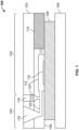
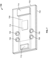
- FIG. 2 illustrates an embodiment of the disclosed system that includes a membrane moving fluids.
- System 200 of FIG. 2 includes a top housing portion 204, and bottom housing portion 212.
- a substrate 208 such as a microscope slide, is held in bottom housing portion 212 and when top housing portion 204 is snapped into place, membrane portions 202, 206, and 210 are brought into contact with substrate 208.
- membrane portion 202 is positioned such that a fluid added to inlet 214 is wicked from membrane portion 202 into membrane portion 206 and across the surface of the substrate 208 where the sample is located to membrane portion 210 that functions as a collector of waste fluids.
- a fluid added to inlet 214 is wicked from membrane portion 202 into membrane portion 206 and across the surface of the substrate 208 where the sample is located to membrane portion 210 that functions as a collector of waste fluids.
- Additional inlets or observation windows 216 and 218 can be included in the top portion 204.
- Sample treatment reagents and control reagents can be included in the membrane portions.
- the conveyor assembly can include a capillary gap to move fluid across a sample held on a substrate.
- system 300 includes a top housing portion 302 and bottom housing portion 306.
- a substrate such as microscope slide 308 is placed so that the sample bearing side is facing toward the bottom housing portion 306. Spacers position the substrate above the bottom housing portion to form a capillary gap 312.
- Conjugate pad 310 is position in proximity to inlet 304 such that a fluid added to the inlet is dissolved from the conjugate pad and carried through the capillary gap, past the sample, and into wicking pad 314.
- Another possible way to move fluid through the disclosed device is utilizing pressure. This is an active way to move the fluid, more suitable for a semi-automated benchtop version of the disclosed system. Pressure driven flow can, for example, be created with syringe pump. Active motivation of fluids can provide faster flow rates and require less tight tolerances in the device, but electricity may be required. Yet another way to move fluid through the disclosed device is utilizing an electric field, which can also provide faster and more controlled flow rates, and less tight tolerances for manufacturing, but electricity is required. Still another alternative is to utilize gravity, as alluded to above. For example, the system can be provided with a tilt to move the fluid. Finally, a user can dispense fluids directly onto the sample on the substrate. While direct dispense permits the device to be simpler, it does create additional user touch points.
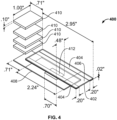
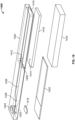
- FIG. 4 illustrates such a configuration.
- a capillary gap forming member 402 having gap forming spacers 404 (which can be adhesive, such as double sided adhesive) is placed in contact with a substrate 408.
- the spacers form the substrate mating assembly.
- the capillary gap forming member 402 is configured to extend beyond a first end of the substrate to provide a fluid application portion 406 that represents the introducer assembly.
- one or more wicking pads 410 are placed (also perhaps with an adhesive) to receive fluid that passes through the capillary space past sample 412.
- the number of stacked wicking pads can be adjusted to provide enough motive force to flow the fluid at an appropriate rate through the device.
- the combination of the capillary space and the wicking pads represents the conveyor assembly, and the wicking pads represent the collector assembly.
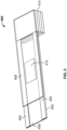
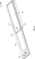
- FIG. 5 shows the system of FIG. 4 in an assembled form, wherein like reference numerals indicate like elements.
- Options for the collector assembly which serves to remove and possibly hold waste fluids, include absorbent wicking pads (such as made from cellulose), a hydrogel, a container (such as filled by a vacuum), or simply permit evaporation at an outlet to reduce waste volume.
- a housing can be part of the disclosed system.
- the housing can function to interface with the slide for alignment purposes, for helping create a seal, and it can be made cheaply to permit cost-effective disposal; and it also serves to protect a sample during treatment.
- all or part of a housing can be constructed of glass, molded plastic, a 3D printed polymer or co-polymer, polydimethylsiloxane ("PDMS”), and other known materials such as metals, metal alloys, and machined plastics.
- PDMS polydimethylsiloxane
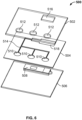
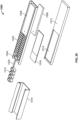
- FIGs. 4 and 5 provide one dimensional fluid conveyance through the system, however, such systems are not limited to one dimensional fluid flow. Indeed, as shown in FIG. 6 , the disclosed system can include 2-dimensional fluid handling capabilities.
- a top introducer assembly housing 502 including fluid inlets 512 and wicking pad window 516 is attached to a substrate mating assembly, which in this instance is a piece of double sided tape.
- the top assembly and the tape can be combined with a wicking pad and provided along with the bottom housing portion 506.
- a polymer or paper covering can be left on the lower side of the double-sided tape until a user is ready to assemble and utilize the device.
- a user would place a substrate bearing a sample in a substrate holding portion (not shown) of the bottom housing portion 506, remove the covering over the lower side of the double-sided tap and place the top introducer assembly housing 502 over the substrate and the bottom housing portion.
- Capillary channels 514 that are formed between the top and bottom housing portions, and defined by the paths in the tape, are used to convey reagent fluids from inlets 512 to a sample treatment portion of the conveyor assembly (not shown). Waste fluids are further conveyed into and absorbed by a wicking pad placed (or pre-placed) in the wicking pad window.
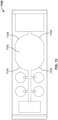
- FIG. 7 illustrates another embodiment of the disclosed system including top and bottom housing portions 702 and 704, where the top housing portion includes biologic reagent inlets 706, wash fluid inlet 712, and wicking pad 714. Fluids introduced into any of the inlets are conveyed through a capillary space over substrate 708 bearing sample 710 to wicking pad 714.
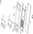
- FIG. 8 shows an exploded view of another embodiment of the disclosed system that is similar to that of the embodiment of FIG. 7 except that the inlets 706 are connected to the sample treatment portion 722 of the conveyor assembly by longer capillary channels.
- the inlets 706 are connected to the sample treatment portion 722 of the conveyor assembly by longer capillary channels.
- Like reference numerals in FIG. 8 as in FIG. 7 correspond to similar elements.
- What is further shown in FIG. 8 is a substrate holding portion 720 of the bottom housing portion, the double-sided tape 703 that serves as a part of the substrate mating assembly, the cut-out in the top housing assembly that accommodates the wicking pad 714, the fluidic channels 724 formed in the tape, and reagent releasers 716 that can be present inside of or place by a user inside of biologic reagent inlets 706.
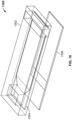
- FIG. 9 shows the embodiment of FIG. 8 in assembled form, where again like reference numerals indicate like elements.
- FIG. 10 illustrates an embodiment of the disclosed system 800 where the introducer assembly, the conveyor assembly and the substrate mating assembly are combined into a monolithic piece 802 that can be directly adhered to a substrate 804 with adhesive tape 806 serving as the substrate mating assembly.
- fluidic channels 812 and 816 are defined by piece 802, substrate 804 and cutouts in the tape 806.
- the sample treatment portion 814 of the conveyor assembly is fluidically connected to wash inlet 808 and reagent inlets 810 by fluidic channel 812 of the introducer assembly.
- the sample treatment portion 814 of the conveyor assembly is connected to the collector assembly 818 of the conveyor assembly by fluidic channel 816.
- a first design did not have capillary channels (see for example, FIG. 7 ). Addition of capillary channels eliminated gradients, reduced bubble formation, and allowed control over flow rate.
- the housing is same size as a slide the slide. Capillary channels were brought closer to fit everything on "slide size”.
- the assembly strategy for the prototype was as follows:
- the geometry of the sample treatment portion 1002 of the system 1000 was changed to include fluid channels at the edges 1004 of the sample treatment portion, and a central fluid channel 1006, were added to try to alleviate incomplete corner filling.
- the assembly strategy was as follows:
- the geometry of the sample treatment portion 1102 of the system 1100 was changed to include larger radius, rounded corners 1104 (such as a radius that is at least 30% of the sample treatment portion's width.
- the assembly strategy for this prototype was as follows:
- the system 1200 included a housing 1202 that included a wash inlet 1204, a set of multiple reagent inlets 1206, and a channel (and capillary space) forming adhesive layer 1210 that included multiple parallel channels located correspondingly to the multiple reagent inlets, but also fluidically connected to the wash inlet and the collector assembly 1208.
- the adhesive layer which is double-sided and can be pre-assembled to housing 1202 can be protected on its other (lower) surface until a substrate 1212 is adhered to the housing to form the functional system.
- the system of this embodiment further included a concentrated reagent cap 1216 that could be attached to a top surface of the housing using a second adhesive layer 1214 that includes a passage to fluidically connect the reagent cap 1216 and the reagent inlets 1206.
- a second adhesive layer 1214 that includes a passage to fluidically connect the reagent cap 1216 and the reagent inlets 1206.
- biologic reagents such as antibodies are often heat labile
- the system can be provided as a kit of the housing assembly with the adhesive layer protected by a covering until attachment to a substrate along with one or more reagent caps that can be, for example, numbered to assist a user in carrying out a predetermined sample treatment protocol.
- the reagent caps can also be pre-assembled with the second adhesive layer and include a protective covering of one side of the adhesive layer that is removed when the cap is place onto the system.
- FIG. 15 shows the embodiment of FIG. 14 in assembled form, where like reference numerals correspond to like elements.
- FIG. 16 shows a simple design wherein the system 1300 includes a housing 1302 including a thin step 1304 in the housing that accepts the substrate.
- a nonreactive grease like Krytox
- the entire monolithic combination of the introducer assembly, the conveyor assembly and the substrate mating assembly mates right over the slide as shown in FIG. 17 , which shows the embodiment of FIG. 16 in assembled form.
- FIG. 18 shows an embodiment of a system 1400 designed to accommodate a larger wicking pad 1416.
- a top housing 1402 that includes an inlet 1404 that is fluidically coupled to a diffuser section 1406 (see also the embodiment of FIG. 16 for this feature) that may spread the reagent more evenly across the substrate within the sample treatment portion 1426 of the conveyor assembly.
- a center and edge fluidic pass through 1408 leads to the collector assembly.
- the collector assembly includes a wicking pad 1416 having a hole 1414 that mates to alignment pin 1412.
- the collector assembly in this embodiment further includes vent 1410 to permit air to be displaced from the collector assembly.
- porous material 1418 placed inside inlet 1404 to help reduce bubble formation.
- a double sided adhesive layer (which can be preassembled with the top housing 1402 and protected with a cover until the system is assembled for use) is used to connect the substrate 1422 to the housing.
- the adhesive layer is used to connect the top housing to a support block 1424 for the wicking pad.
- FIG. 19 shows the embodiment of FIG. 18 in assembled form, where like reference numerals correspond to like elements.
- FIG. 20 shows a further embodiment, similar to the embodiment of figure 18 , where the system 1500 includes a top housing 1502 (which in this case is injection molded plastic) and the flow channel is impressed into the mold.
- a "living hinge" 1520 allows pre-packed chemicals 1510 to be moved over the fluid inlet 1504.
- the top housing 1502 also includes a recess 1506 to accommodate the wicking pad 1508.
- the embodiment further includes a bottom housing 1512 with a recess 1514 configured to accept a substrate 1516, and the embodiment further includes a clamping assembly 1518 that serves to hold the entire assembly together as shown in FIG. 21 , where like reference numerals correspond to like elements. Not shown are locating bumps for proper alignment of the bottom and top housings.
- wicking pad chamber There is room in the wicking pad chamber for it to expand, but there is also a locating pin in the chamber to prevent the pad from moving around. There can also be an exit channel past the wicking pad to allow for displaced air.
- the slide sits slightly proud of top surface of the bottom housing in the recess.
- a sealing member such as an adhesive layer or grease are optional if the plastic from which the assembly is molded is soft enough.
- indicia can be added to, for example, each of the pre-packed chemicals so that they are labeled with the numerical order in which they are to be used.
- FIG. 22 shows a particular embodiment of a 3-dimensional reagent releaser for releasing multiple reagents in succession.
- the releaser can be placed within a capillary channel and as, for example, when a buffer is flowed past the releaser, the releaser dissolves to permit the different reagents to reach the cellular biological sample.
- FIG 23 shows a process diagram showing a general workflow for immunohistochemical (IHC) staining process that can be carried out using the disclosed system according to certain embodiments.
- IHC immunohistochemical
- FIG. 24 shows a generalized IHC protocol that can be performed, for example, on a formalin-fixed paraffin-embedded tissue sample.
- a protocol can, at least in part, be performed using the disclosed system according to certain embodiments.
- the sample is de-paraffinized, a step that may be performed separately before mounting a substrate bearing the tissue sample to the disclosed system.
- antigen retrieval which is typically accomplished with head and/or pressure, can be performed using the disclosed system in an embodiment as discussed further below.
- an inhibitor may be added to help prevent non-specific binding of the primary antibody added in step 1604. If the primary antibody is directly detectable (such as by fluorescence microscopy) steps 1606 and 1608 are optional.
- IHC staining can be used to detect particular antigens (such as biomarkers for disease) in a cellular sample, to detect viral particles and to detect certain pathogenic bacteria.
- IHC assays will require a "hot step” to facilitate binding of antibody to antigen or to create optimal reaction conditions for enzymatic detection steps as part of an assay detection stack.
- a hot step to facilitate binding of antibody to antigen or to create optimal reaction conditions for enzymatic detection steps as part of an assay detection stack.
- autostainers this is typically done as a function of the instrument (e.g. a heater plate for the slide, temperature control of the overall instrument, or a temperature controlled staining fluid).
- the instrument e.g. a heater plate for the slide, temperature control of the overall instrument, or a temperature controlled staining fluid.
- these steps may be performed on a hot plate or in an incubation chamber.
- the POC device described here may be used in a similar manner, but with some unique attributes.
- the POC device housing provides an evaporative barrier.
- the POC device housing provides an evaporative barrier.
- the exposed surface area of fluid is greatly reduced.
- the POC device in some embodiments may be compatible with incubation chambers.
- an incubation chamber may be used.
- an antigen retrieval fluid is applied via the introduction port on the POC device to wet out the slide and tissue within the capillary gap space.
- the entire assembly (Slide + Fluid + POC device) may be placed in the incubation chamber.
- the advantage is that due to the coverage provided by the device, evaporation rates can be lower than uncovered slides.
- the device since the device has a reservoir to hold additional fluid the device may replenish fluid on the slide and tissue automatically during hot incubation. Finally, this device does not preclude the use in a pressurized incubation chamber.
- heating may be incorporated into the POC device is via the integration of a thin-film heater into the device.
- a coating of a conductive thin film may be applied. Examples include but are not limited to indium tin oxide (ITO), SiOiCr, Nichorme (NiCr), or Tantalum Nitride (TaN).
- Compatible materials (substrate) for the POC device may include acrylics, polycarbonates, glass, polyether ether ketone (“PEEK”), cyclic olefin copolymer (“COC”), and PDMS.
- Methods of manufacture include direct ion beam sputter coating (particularly for a glass substrate), lamination, or the addition of an epoxy to the POC device surface.
- the heater may be built up on the POC device surface while for other methods, the heater is fabricated separately and then bonded to the surface of the POC device facing the fluid, tissue, and microscope slide.
- Patterns include continuous thin film surface, grid patterning of metal or metal oxide, or a wound wire pattern on the surface.
- the differences include the ability to deliver a high-power density for patterned wire heaters and the ability to create heating gradients with a thin film layer depending upon the placement of bus bars.
- a thermal gradient may be used to enhance mixing as molecular diffusion will be increased across the temperature gradient as well as bulk transport phenomenon to alleviate the temperature gradient.
- Insulation of the heater may be achieved by the application of another thin film layer (SiO2 for example) or the lamination of a non-conductive polymer layer such as polyethylene terephthalate (“PET”) or Kapton ® (a polyimide film available from Dupont).
- a non-conductive polymer layer such as polyethylene terephthalate (“PET”) or Kapton ® (a polyimide film available from Dupont).
- Bus bars to be included may be sputtered metal, a wraparound conductive metal contact to the other (non-fluid facing) side of the POC top plate, or copper (conductive tape) or conductive epoxy (e.g. the conductive epoxy may be a standard epoxy filled with an electrically conductive material, such as metal elements (for example gold and silver), metalloids, or other material such as carbon, which by filling the standard epoxy results in a conductive epoxy).
- Suitable conductive epoxies include, without limitation, commercially available silver epoxies, nickel epoxies, chromium epoxies, gold epoxies, tungsten epoxies, alloy epoxies and combinations thereof.
- the conductive epoxies are selected from Tra-Duct ® 2902 silver epoxy (available from Tra-Con, Inc.) and Applied Technologies 5933 alloy (70/25/5 weight percent Ag/Au/Ni) epoxy (available from Applied Technologies).
- the conductive epoxy is an EPOXIES 40-3905 (an electrically conductive epoxy adhesive and coating designed for applications requiring low temperature cures) or an EPOXIES 40-3900 (an electrically conductive epoxy resin filled with pure silver), both available from EPOXIES, Cranston, RI.
- the conductive epoxy is AGCL-823, a silver /silver chloride electrically conductive epoxy, available from Conductive Compounds, Hudson, J.
- Relevant operating temperatures for the device may be up to about 120C for sustained periods of time, with a maximum power density up to about10W/in2.
- Control of heating may be via direct modulation of the DC voltage applied to the heater, or through the use of a pulse width modulation scheme at a fixed DC voltage to be applied.
- Power may be delivered to the device by connecting a supply to the bus bars or other contact surfaces built off of the bus bars.
- mild heating extends the capability and flexibility of the device.
- a mild antigen retrieval step is recommended (about 80C for about 15min). This act of unmasking antigens may improve the overall sensitivity of the test result provided when using the POC of the device.
- tissue-based assays it is required to do some amount of antigen retrieval prior to IHC in order to linearize the epitopes for binding. Without the ability to apply heat, that sub-set of IHC assays would not be compatible with this device.
- elements of the introducer assembly, the conveyor assembly and the substrate mating assembly can be mixed and matched in one or more modules that are used to assemble the system for use in preparing a substrate mounted cellular biological sample.
- a dispenser or “the dispenser” includes one or one or more dispensers.
- the term “about” refers to plus or minus 10% of the referenced number's value, for example plus or minus 5% of the referenced number's value such as plus or minus 1% of the referenced number's value.
- references to the invention described herein using the phrase “comprising” includes embodiments that could be described as “consisting of”, and as such the written description requirement for claiming one or more embodiments of the present invention using the phrase “consisting of” is met.
- stain generally refers to any treatment of a biological specimen that detects and/or differentiates the presence, location, and/or amount (such as concentration) of a particular molecule (such as a lipid, protein or nucleic acid) or particular structure (such as a normal or malignant cell, cytosol, nucleus, Golgi apparatus, or cytoskeleton) in the biological specimen.
- a particular molecule such as a lipid, protein or nucleic acid
- particular structure such as a normal or malignant cell, cytosol, nucleus, Golgi apparatus, or cytoskeleton
- staining can provide contrast between a particular molecule or a particular cellular structure and surrounding portions of a biological specimen, and the intensity of the staining can provide a measure of the amount of a particular molecule in the specimen.
- Staining can be used to aid in the viewing of molecules, cellular structures and organisms not only with bright-field microscopes, but also with other viewing tools, such as phase contrast microscopes, electron microscopes, and fluorescence microscopes.
- Some staining performed by the system 2 can be used to visualize an outline of a cell.
- Other staining performed by the system 2 may rely on certain cell components (such as molecules or structures) being stained without or with relatively little staining other cell components.
- types of staining methods performed by the system 2 include, without limitation, histochemical methods, immunohistochemical methods, and other methods based on reactions between molecules (including non-covalent binding interactions), such as hybridization reactions between nucleic acid molecules.
- Particular staining methods include, but are not limited to, primary staining methods (e.g., H&E staining, Pap staining, etc.), enzyme-linked immunohistochemical methods, and in situ RNA and DNA hybridization methods, such as fluorescence in situ hybridization (FISH).
- primary staining methods e.g., H&E staining, Pap staining, etc.
- enzyme-linked immunohistochemical methods e.g., Pap staining, etc.
- in situ RNA and DNA hybridization methods such as fluorescence in situ hybridization (FISH).
Landscapes
- Chemical & Material Sciences (AREA)
- Health & Medical Sciences (AREA)
- Analytical Chemistry (AREA)
- General Health & Medical Sciences (AREA)
- Chemical Kinetics & Catalysis (AREA)
- Hematology (AREA)
- Clinical Laboratory Science (AREA)
- Life Sciences & Earth Sciences (AREA)
- Dispersion Chemistry (AREA)
- Engineering & Computer Science (AREA)
- Biomedical Technology (AREA)
- Molecular Biology (AREA)
- Physics & Mathematics (AREA)
- Biochemistry (AREA)
- General Physics & Mathematics (AREA)
- Immunology (AREA)
- Pathology (AREA)
- Sampling And Sample Adjustment (AREA)
Claims (8)
- System (100, 200, 300, 400, 500, 800, 900, 1000, 1100, 1200, 1300, 1400, 1500) zum Vorbereiten einer zellulären biologischen Probe zur Analyse, wobei die zelluläre biologische Probe auf einem Substrat (108, 208, 308, 408, 708, 804, 1212, 1422, 1516) aufgezogen ist, umfassend:a. eine Einleiteinrichtung (102), die zwei oder mehr Einlässe (116 oder 118), die dafür ausgebildet sind, mindestens eine Flüssigkeit aufzunehmen, die zum Vorbereiten der zellulären biologischen Probe zur Analyse verwendet wird, und Indikatoren, die die Reihenfolge spezifizieren, in der die mindestens eine Flüssigkeit in die zwei oder mehr Flüssigkeitseinlässe der Einleiteinrichtung eingeleitet wird, einschließt;b. eine Fördereinrichtung (104), die dafür ausgebildet ist, die mindestens eine Flüssigkeit über mindestens einen Teil des Substrats (108, 208, 308, 408, 708, 804, 1212, 1422, 1516) zu bewegen, wobei die Fördereinrichtung (i) einen Behandlungsteil (110), in dem die mindestens eine Flüssigkeit mit mindestens einem Teil der zellulären biologischen Probe in Kontakt kommt; (ii) einen Kapillardurchlauf, der fluidisch an den einen Einlass oder die mehreren Einlässe und den Behandlungsteil (110) gekoppelt ist; und (iii) eine Flüssigkeitsauffangeinrichtung in Fluidkommunikation mit dem Behandlungsteil (110) einschließt, wobei die Flüssigkeitsauffangeinrichtung ein Saugkissen einschließt, das Flüssigkeit aus dem Probenbehandlungsteil (110) aufnimmt und eine Antriebskraft zum Bewegen von Flüssigkeiten aus dem einen Einlass oder den mehreren Einlässen (116 oder 118) der Einleiteinrichtung (102) durch den Probenbehandlungsteil (110) bereitstellt; undeine Substratverbindungseinrichtung (106), die dafür ausgebildet ist, das Substrat (108, 208, 308, 408, 708, 804, 1212, 1422, 1516) gegen mindestens einen Teil der Fördereinrichtung (104) zu halten.
- System nach Anspruch 1, wobei das Substrat einen Mikroskopobjektträger (308) umfasst.
- System nach einem der Ansprüche 1 bis 2, ferner umfassend eine Flüssigkeitsabgabesteuerungseinheit, die dafür ausgebildet ist, sich mit den zwei oder mehr Flüssigkeitseinlässen (512, 712, 1504) der Einleiteinrichtung (102) zu verbinden.
- System nach einem der Ansprüche 1 bis 3, wobei die Einleiteinrichtung (102) ferner mindestens einen Reagenzfreisetzer umfasst, wobei der mindestens eine Reagenzfreisetzer (120, 716) eines oder mehreres von einem getrockneten Reagenz, das auf eine Oberfläche der Einleiteinrichtung (102) gedruckt ist, einem lösbaren Polymer, das ein Reagenz umfasst, einem porösen Membrankissen, das ein Reagenz umfasst, einem Partikel, das ein Reagenz umfasst, und einer Blisterpackung umfasst.
- System nach einem der Ansprüche 1 bis 4, wobei die Substratverbindungseinrichtung (106) ferner eine Rückenplatte (126) umfasst, die einen Halteteil einschließt, der dafür ausgebildet ist, das Substrat (108, 208, 408, 708, 804, 1212, 1422, 1516) nach der Fördereinrichtung (104) auszurichten, wenn die Rückenplatte (126) und die Fördereinrichtung (104) vereinigt sind.
- Verfahren zum Vorbereiten einer zellulären Probe zur mikroskopischen Analyse, wobei die zelluläre Probe auf einem Mikroskopobjektträger (308) aufgezogen wird, umfassend:a. Verbinden eines Systems (100, 200, 300, 400, 500, 800, 900, 1000, 1100, 1200, 1300, 1400, 1500) nach einem der Ansprüche 1 bis 5 mit dem Mikroskopobjektträger (308);b. Abgeben einer vorbestimmten Reihe von Reagenzien an einen Probenbehandlungsteil der Fördereinrichtung (104), der mindestens einen Teil der zellulären Probe bedeckt und die vorbestimmte Reihe von Reagenzien mit der zellulären Probe in Kontakt bringt, über die zwei oder mehr Einlässe (116 oder 118) der Einleiteinrichtung (102) undc. sukzessives Entfernen der Reihe von Reagenzien aus dem Probenbehandlungsteil in eine Auffangeinrichtung (114, 818, 1208) der Fördereinrichtung (104).
- Kit, umfassend:a. ein System (100, 200, 300, 400, 500, 800, 900, 1000, 1100, 1200, 1300, 1400, 1500) nach einem der Ansprüche 1 bis 5 undb. Anweisungen zur Verwendung des Systems (100, 200, 300, 400, 500, 800, 900, 1000, 1100, 1200, 1300, 1400, 1500) zum Ausführen des Verfahrens nach Anspruch 6.
- Kit nach Anspruch 7, ferner umfassend einen Mikroskopobjektträger (308), wobei der Mikroskopobjektträger (308) behandelt ist, um das Anhaften von Zellen an dem Mikroskopobjektträger (308) zu verbessern.
Applications Claiming Priority (2)
| Application Number | Priority Date | Filing Date | Title |
|---|---|---|---|
| US201662405129P | 2016-10-06 | 2016-10-06 | |
| PCT/US2017/055503 WO2018067910A1 (en) | 2016-10-06 | 2017-10-06 | System, method and kit for sample preparation |
Publications (2)
| Publication Number | Publication Date |
|---|---|
| EP3523622A1 EP3523622A1 (de) | 2019-08-14 |
| EP3523622B1 true EP3523622B1 (de) | 2025-04-30 |
Family
ID=60183118
Family Applications (1)
| Application Number | Title | Priority Date | Filing Date |
|---|---|---|---|
| EP17790902.5A Active EP3523622B1 (de) | 2016-10-06 | 2017-10-06 | System, verfahren und kit zur probenvorbereitung |
Country Status (3)
| Country | Link |
|---|---|
| US (1) | US20190234842A1 (de) |
| EP (1) | EP3523622B1 (de) |
| WO (1) | WO2018067910A1 (de) |
Families Citing this family (1)
| Publication number | Priority date | Publication date | Assignee | Title |
|---|---|---|---|---|
| US20240261781A1 (en) * | 2023-02-07 | 2024-08-08 | Bonraybio Co., Ltd. | Biological sample testing device, systems, and methods |
Citations (3)
| Publication number | Priority date | Publication date | Assignee | Title |
|---|---|---|---|---|
| US5104813A (en) * | 1989-04-13 | 1992-04-14 | Biotrack, Inc. | Dilution and mixing cartridge |
| WO2013106458A2 (en) * | 2012-01-09 | 2013-07-18 | Micronics, Inc. | Microfluidic reactor system |
| US20150316454A1 (en) * | 2012-12-13 | 2015-11-05 | Koninklijke Philips N.V. | Cartridge and apparatus for preparing a biological sample |
Family Cites Families (9)
| Publication number | Priority date | Publication date | Assignee | Title |
|---|---|---|---|---|
| US4301115A (en) * | 1979-06-22 | 1981-11-17 | Miles Laboratories, Inc. | Test device resistant to cross contamination between reactant areas and process for making it |
| US5188963A (en) * | 1989-11-17 | 1993-02-23 | Gene Tec Corporation | Device for processing biological specimens for analysis of nucleic acids |
| CA2315809C (en) * | 1997-12-23 | 2014-06-03 | Dako A/S | Cartridge device for processing a sample mounted on a surface of a support member |
| WO2001026813A2 (en) * | 1999-10-08 | 2001-04-19 | Micronics, Inc. | Microfluidics without electrically of mechanically operated pumps |
| US7754155B2 (en) * | 2002-03-15 | 2010-07-13 | Ross Amelia A | Devices and methods for isolating target cells |
| CN101754812B (zh) * | 2007-05-04 | 2013-06-26 | 克拉洛诊断仪器公司 | 流体连接器和微流体系统 |
| WO2008147865A1 (en) * | 2007-05-22 | 2008-12-04 | Diamics, Inc. | Point of care cervical screening system |
| CN101281191B (zh) * | 2007-11-14 | 2012-10-10 | 石西增 | 一种对磁敏传感生物芯片进行自动测量的仪器 |
| JP6359348B2 (ja) * | 2014-06-06 | 2018-07-18 | キヤノンメディカルシステムズ株式会社 | センサチップ及びセンサチップへの液体供給方法 |
-
2017
- 2017-10-06 EP EP17790902.5A patent/EP3523622B1/de active Active
- 2017-10-06 WO PCT/US2017/055503 patent/WO2018067910A1/en not_active Ceased
-
2019
- 2019-04-05 US US16/376,001 patent/US20190234842A1/en not_active Abandoned
Patent Citations (3)
| Publication number | Priority date | Publication date | Assignee | Title |
|---|---|---|---|---|
| US5104813A (en) * | 1989-04-13 | 1992-04-14 | Biotrack, Inc. | Dilution and mixing cartridge |
| WO2013106458A2 (en) * | 2012-01-09 | 2013-07-18 | Micronics, Inc. | Microfluidic reactor system |
| US20150316454A1 (en) * | 2012-12-13 | 2015-11-05 | Koninklijke Philips N.V. | Cartridge and apparatus for preparing a biological sample |
Also Published As
| Publication number | Publication date |
|---|---|
| EP3523622A1 (de) | 2019-08-14 |
| WO2018067910A1 (en) | 2018-04-12 |
| US20190234842A1 (en) | 2019-08-01 |
Similar Documents
| Publication | Publication Date | Title |
|---|---|---|
| US20240253036A1 (en) | Fluid delivery methods | |
| CN110959118B (zh) | 用于基于gmr的生物标志物检测中的试样制备的系统和方法 | |
| US9925538B2 (en) | System and method for capturing and analyzing cells | |
| US10697868B2 (en) | In situ heat induced antigen recovery and staining apparatus and method | |
| US11325120B2 (en) | Specimen treatment chip, specimen treatment apparatus, and specimen treatment method | |
| US20210172968A1 (en) | Automated slide processing systems, consumable stainer units, and related technologies | |
| EP2597471A2 (de) | Mikrointegriertes Analysesystem, Prüfchip und Prüfverfahren | |
| JP2025138764A (ja) | 生体試料の染色システムおよび方法 | |
| CN101218032A (zh) | 综合和自动化的dna或蛋白质分析系统及其运行方法 | |
| EP3824266B1 (de) | Automatisiertes system zum anfärben von objektträgern und verfahren zur verarbeitung einer probe | |
| EP3824265B1 (de) | Automatisiertes färbesystem | |
| CN104837560A (zh) | 用于制备生物样品的盒和装置 | |
| CN105229442A (zh) | 组织从样本分离 | |
| EP3523622B1 (de) | System, verfahren und kit zur probenvorbereitung | |
| WO2017203744A1 (ja) | 核酸検査装置 | |
| JP6084370B2 (ja) | 組織化学用自動反応装置 | |
| CA3203372A1 (en) | Chemical processing system, instrument and sample cartridge | |
| CN116457100A (zh) | 样品处理设备和流体输送方法 | |
| EP3990178A1 (de) | Kassette, system zur elektrobenetzungsprobenverarbeitung und zuführung dafür | |
| US20250144623A1 (en) | Chemical processing system, instrument and sample cartridge | |
| CN116472116A (zh) | 流体输送方法 |
Legal Events
| Date | Code | Title | Description |
|---|---|---|---|
| STAA | Information on the status of an ep patent application or granted ep patent |
Free format text: STATUS: UNKNOWN |
|
| STAA | Information on the status of an ep patent application or granted ep patent |
Free format text: STATUS: THE INTERNATIONAL PUBLICATION HAS BEEN MADE |
|
| PUAI | Public reference made under article 153(3) epc to a published international application that has entered the european phase |
Free format text: ORIGINAL CODE: 0009012 |
|
| STAA | Information on the status of an ep patent application or granted ep patent |
Free format text: STATUS: REQUEST FOR EXAMINATION WAS MADE |
|
| 17P | Request for examination filed |
Effective date: 20190411 |
|
| AK | Designated contracting states |
Kind code of ref document: A1 Designated state(s): AL AT BE BG CH CY CZ DE DK EE ES FI FR GB GR HR HU IE IS IT LI LT LU LV MC MK MT NL NO PL PT RO RS SE SI SK SM TR |
|
| AX | Request for extension of the european patent |
Extension state: BA ME |
|
| DAV | Request for validation of the european patent (deleted) | ||
| DAX | Request for extension of the european patent (deleted) | ||
| STAA | Information on the status of an ep patent application or granted ep patent |
Free format text: STATUS: EXAMINATION IS IN PROGRESS |
|
| 17Q | First examination report despatched |
Effective date: 20220131 |
|
| GRAP | Despatch of communication of intention to grant a patent |
Free format text: ORIGINAL CODE: EPIDOSNIGR1 |
|
| STAA | Information on the status of an ep patent application or granted ep patent |
Free format text: STATUS: GRANT OF PATENT IS INTENDED |
|
| RIC1 | Information provided on ipc code assigned before grant |
Ipc: B01L 3/00 20060101ALI20250122BHEP Ipc: G01N 1/31 20060101AFI20250122BHEP |
|
| INTG | Intention to grant announced |
Effective date: 20250130 |
|
| GRAS | Grant fee paid |
Free format text: ORIGINAL CODE: EPIDOSNIGR3 |
|
| GRAA | (expected) grant |
Free format text: ORIGINAL CODE: 0009210 |
|
| STAA | Information on the status of an ep patent application or granted ep patent |
Free format text: STATUS: THE PATENT HAS BEEN GRANTED |
|
| AK | Designated contracting states |
Kind code of ref document: B1 Designated state(s): AL AT BE BG CH CY CZ DE DK EE ES FI FR GB GR HR HU IE IS IT LI LT LU LV MC MK MT NL NO PL PT RO RS SE SI SK SM TR |
|
| REG | Reference to a national code |
Ref country code: CH Ref legal event code: EP Ref country code: GB Ref legal event code: FG4D |
|
| REG | Reference to a national code |
Ref country code: DE Ref legal event code: R096 Ref document number: 602017089214 Country of ref document: DE |
|
| REG | Reference to a national code |
Ref country code: IE Ref legal event code: FG4D |
|
| REG | Reference to a national code |
Ref country code: NL Ref legal event code: MP Effective date: 20250430 |
|
| REG | Reference to a national code |
Ref country code: AT Ref legal event code: MK05 Ref document number: 1790420 Country of ref document: AT Kind code of ref document: T Effective date: 20250430 |
|
| PG25 | Lapsed in a contracting state [announced via postgrant information from national office to epo] |
Ref country code: PT Free format text: LAPSE BECAUSE OF FAILURE TO SUBMIT A TRANSLATION OF THE DESCRIPTION OR TO PAY THE FEE WITHIN THE PRESCRIBED TIME-LIMIT Effective date: 20250901 Ref country code: FI Free format text: LAPSE BECAUSE OF FAILURE TO SUBMIT A TRANSLATION OF THE DESCRIPTION OR TO PAY THE FEE WITHIN THE PRESCRIBED TIME-LIMIT Effective date: 20250430 Ref country code: ES Free format text: LAPSE BECAUSE OF FAILURE TO SUBMIT A TRANSLATION OF THE DESCRIPTION OR TO PAY THE FEE WITHIN THE PRESCRIBED TIME-LIMIT Effective date: 20250430 |
|
| REG | Reference to a national code |
Ref country code: LT Ref legal event code: MG9D |
|
| PG25 | Lapsed in a contracting state [announced via postgrant information from national office to epo] |
Ref country code: NO Free format text: LAPSE BECAUSE OF FAILURE TO SUBMIT A TRANSLATION OF THE DESCRIPTION OR TO PAY THE FEE WITHIN THE PRESCRIBED TIME-LIMIT Effective date: 20250730 Ref country code: GR Free format text: LAPSE BECAUSE OF FAILURE TO SUBMIT A TRANSLATION OF THE DESCRIPTION OR TO PAY THE FEE WITHIN THE PRESCRIBED TIME-LIMIT Effective date: 20250731 |
|
| PG25 | Lapsed in a contracting state [announced via postgrant information from national office to epo] |
Ref country code: PL Free format text: LAPSE BECAUSE OF FAILURE TO SUBMIT A TRANSLATION OF THE DESCRIPTION OR TO PAY THE FEE WITHIN THE PRESCRIBED TIME-LIMIT Effective date: 20250430 Ref country code: NL Free format text: LAPSE BECAUSE OF FAILURE TO SUBMIT A TRANSLATION OF THE DESCRIPTION OR TO PAY THE FEE WITHIN THE PRESCRIBED TIME-LIMIT Effective date: 20250430 |
|
| PG25 | Lapsed in a contracting state [announced via postgrant information from national office to epo] |
Ref country code: BG Free format text: LAPSE BECAUSE OF FAILURE TO SUBMIT A TRANSLATION OF THE DESCRIPTION OR TO PAY THE FEE WITHIN THE PRESCRIBED TIME-LIMIT Effective date: 20250430 |
|
| PG25 | Lapsed in a contracting state [announced via postgrant information from national office to epo] |
Ref country code: HR Free format text: LAPSE BECAUSE OF FAILURE TO SUBMIT A TRANSLATION OF THE DESCRIPTION OR TO PAY THE FEE WITHIN THE PRESCRIBED TIME-LIMIT Effective date: 20250430 |
|
| PG25 | Lapsed in a contracting state [announced via postgrant information from national office to epo] |
Ref country code: AT Free format text: LAPSE BECAUSE OF FAILURE TO SUBMIT A TRANSLATION OF THE DESCRIPTION OR TO PAY THE FEE WITHIN THE PRESCRIBED TIME-LIMIT Effective date: 20250430 |
|
| PG25 | Lapsed in a contracting state [announced via postgrant information from national office to epo] |
Ref country code: RS Free format text: LAPSE BECAUSE OF FAILURE TO SUBMIT A TRANSLATION OF THE DESCRIPTION OR TO PAY THE FEE WITHIN THE PRESCRIBED TIME-LIMIT Effective date: 20250731 |
|
| PG25 | Lapsed in a contracting state [announced via postgrant information from national office to epo] |
Ref country code: IS Free format text: LAPSE BECAUSE OF FAILURE TO SUBMIT A TRANSLATION OF THE DESCRIPTION OR TO PAY THE FEE WITHIN THE PRESCRIBED TIME-LIMIT Effective date: 20250830 |
|
| PG25 | Lapsed in a contracting state [announced via postgrant information from national office to epo] |
Ref country code: LV Free format text: LAPSE BECAUSE OF FAILURE TO SUBMIT A TRANSLATION OF THE DESCRIPTION OR TO PAY THE FEE WITHIN THE PRESCRIBED TIME-LIMIT Effective date: 20250430 |
|
| PGFP | Annual fee paid to national office [announced via postgrant information from national office to epo] |
Ref country code: DE Payment date: 20250923 Year of fee payment: 9 |
|
| PG25 | Lapsed in a contracting state [announced via postgrant information from national office to epo] |
Ref country code: DK Free format text: LAPSE BECAUSE OF FAILURE TO SUBMIT A TRANSLATION OF THE DESCRIPTION OR TO PAY THE FEE WITHIN THE PRESCRIBED TIME-LIMIT Effective date: 20250430 Ref country code: SM Free format text: LAPSE BECAUSE OF FAILURE TO SUBMIT A TRANSLATION OF THE DESCRIPTION OR TO PAY THE FEE WITHIN THE PRESCRIBED TIME-LIMIT Effective date: 20250430 |