EP3522955B1 - Dispositif d'injection manuelle. - Google Patents
Dispositif d'injection manuelle. Download PDFInfo
- Publication number
- EP3522955B1 EP3522955B1 EP17793988.1A EP17793988A EP3522955B1 EP 3522955 B1 EP3522955 B1 EP 3522955B1 EP 17793988 A EP17793988 A EP 17793988A EP 3522955 B1 EP3522955 B1 EP 3522955B1
- Authority
- EP
- European Patent Office
- Prior art keywords
- injection
- reservoir
- lower body
- sleeve
- injection device
- Prior art date
- Legal status (The legal status is an assumption and is not a legal conclusion. Google has not performed a legal analysis and makes no representation as to the accuracy of the status listed.)
- Active
Links
Images

Classifications
-
- A—HUMAN NECESSITIES
- A61—MEDICAL OR VETERINARY SCIENCE; HYGIENE
- A61M—DEVICES FOR INTRODUCING MEDIA INTO, OR ONTO, THE BODY; DEVICES FOR TRANSDUCING BODY MEDIA OR FOR TAKING MEDIA FROM THE BODY; DEVICES FOR PRODUCING OR ENDING SLEEP OR STUPOR
- A61M5/00—Devices for bringing media into the body in a subcutaneous, intra-vascular or intramuscular way; Accessories therefor, e.g. filling or cleaning devices, arm-rests
- A61M5/178—Syringes
- A61M5/31—Details
- A61M5/32—Needles; Details of needles pertaining to their connection with syringe or hub; Accessories for bringing the needle into, or holding the needle on, the body; Devices for protection of needles
- A61M5/3287—Accessories for bringing the needle into the body; Automatic needle insertion
-
- A—HUMAN NECESSITIES
- A61—MEDICAL OR VETERINARY SCIENCE; HYGIENE
- A61M—DEVICES FOR INTRODUCING MEDIA INTO, OR ONTO, THE BODY; DEVICES FOR TRANSDUCING BODY MEDIA OR FOR TAKING MEDIA FROM THE BODY; DEVICES FOR PRODUCING OR ENDING SLEEP OR STUPOR
- A61M5/00—Devices for bringing media into the body in a subcutaneous, intra-vascular or intramuscular way; Accessories therefor, e.g. filling or cleaning devices, arm-rests
- A61M5/178—Syringes
- A61M5/31—Details
- A61M5/3129—Syringe barrels
-
- A—HUMAN NECESSITIES
- A61—MEDICAL OR VETERINARY SCIENCE; HYGIENE
- A61M—DEVICES FOR INTRODUCING MEDIA INTO, OR ONTO, THE BODY; DEVICES FOR TRANSDUCING BODY MEDIA OR FOR TAKING MEDIA FROM THE BODY; DEVICES FOR PRODUCING OR ENDING SLEEP OR STUPOR
- A61M5/00—Devices for bringing media into the body in a subcutaneous, intra-vascular or intramuscular way; Accessories therefor, e.g. filling or cleaning devices, arm-rests
- A61M5/178—Syringes
- A61M5/31—Details
- A61M5/32—Needles; Details of needles pertaining to their connection with syringe or hub; Accessories for bringing the needle into, or holding the needle on, the body; Devices for protection of needles
- A61M5/3205—Apparatus for removing or disposing of used needles or syringes, e.g. containers; Means for protection against accidental injuries from used needles
- A61M5/321—Means for protection against accidental injuries by used needles
- A61M5/3243—Means for protection against accidental injuries by used needles being axially-extensible, e.g. protective sleeves coaxially slidable on the syringe barrel
- A61M5/326—Fully automatic sleeve extension, i.e. in which triggering of the sleeve does not require a deliberate action by the user
-
- A—HUMAN NECESSITIES
- A61—MEDICAL OR VETERINARY SCIENCE; HYGIENE
- A61M—DEVICES FOR INTRODUCING MEDIA INTO, OR ONTO, THE BODY; DEVICES FOR TRANSDUCING BODY MEDIA OR FOR TAKING MEDIA FROM THE BODY; DEVICES FOR PRODUCING OR ENDING SLEEP OR STUPOR
- A61M5/00—Devices for bringing media into the body in a subcutaneous, intra-vascular or intramuscular way; Accessories therefor, e.g. filling or cleaning devices, arm-rests
- A61M5/178—Syringes
- A61M5/31—Details
- A61M5/32—Needles; Details of needles pertaining to their connection with syringe or hub; Accessories for bringing the needle into, or holding the needle on, the body; Devices for protection of needles
- A61M5/3205—Apparatus for removing or disposing of used needles or syringes, e.g. containers; Means for protection against accidental injuries from used needles
- A61M5/321—Means for protection against accidental injuries by used needles
- A61M5/3243—Means for protection against accidental injuries by used needles being axially-extensible, e.g. protective sleeves coaxially slidable on the syringe barrel
- A61M5/326—Fully automatic sleeve extension, i.e. in which triggering of the sleeve does not require a deliberate action by the user
- A61M2005/3267—Biased sleeves where the needle is uncovered by insertion of the needle into a patient's body
Definitions
- the present invention relates to a manual injection device.
- manual injection devices The main purpose of manual injection devices is to achieve penetration of the needle into the patient's body as well as to protect the needle of the syringe before, during and after injection.
- the injection into the patient's body of the product contained in the syringe is carried out manually by the user.
- Manual injection devices are relatively complex devices which must meet a certain number of stress requirements in order to be reliable. The robustness of the device, its maneuverability, and its ease of use for the user are also important elements. Furthermore, since most of these manual injection devices are disposable, the cost of manufacture and assembly is also a factor to be taken into account.
- the use of the manual injection device should not be too difficult, which would prevent weak people from using it. It is also important to prevent the injection from starting before the needle has entered the patient's body.
- the manual injection device in order to avoid any risk of injury before and after use of the device, the manual injection device must include a needle safety device which prevents the needle from being visible before and after use of the device. . This safety device must obviously also be reliable and not release too easily. It must also be functional even if the user improperly actuates the manual injection device, for example if he withdraws it too early from his body, before the end of the injection.
- the object of the present invention is to provide a manual injection device which does not reproduce the aforementioned drawbacks, and which allows to meet the various requirements and significant constraints for safe and reliable use of the manual injection device.
- the present invention aims in particular to provide a manual injection device which avoids the risk of the injection of the product starting before the needle has completely penetrated the injection site.
- Another object of the present invention is to provide a manual injection device which is reliable in use, which is safe and which prevents any risk of injury, and which is simple and inexpensive to manufacture and to assemble.
- said piston rod before actuation, is connected by breakable bridges to said ring.
- said ring has a radially internal projection cooperating, before actuation, with a groove of said piston rod.
- said sleeve comprises an end elastically deformable radially inwards, said end resting in the rest position on a radial shoulder of the lower body, said upper body cooperating at the end of injection via a cam with said end of said sleeve, in order to deform said end radially inward.
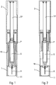
- the manual injection device shown in the figures comprises a lower body 1 and an upper body 2, axially displaceable relative to said lower body 1 during actuation.
- the bodies lower 1 and upper 2 can be made in one piece or in several assembled parts.
- this lower body 1 contains a reservoir S containing the product to be injected, a needle A fixed to said reservoir S through which the product is dispensed and a piston P adapted to move in said reservoir S to perform this injection.
- the upper body 2 comprises a piston rod TP cooperating with said piston P during injection in order to move it in the reservoir S.
- the needle A can be protected before use by a protective cap.
- the reservoir S can typically be a conventional pre-filled syringe, provided with a radial flange 9.
- Said reservoir S is movable axially in said lower body 1 to carry out the stitching, then is fixed relative to said lower body 1 during the injection.
- Said TP piston rod is fixed relative to said upper body 2.
- a post-injection safety sleeve 10 is placed inside the lower body. After the injection, said sleeve 10 is moved axially out of the lower body 1 in a projected position, in which it is arranged around the needle A, to avoid any risk of injury with said needle A, thus forming a safety device post-injection.
- the sleeve 10 is advantageously biased towards its projected position by a spring, which can be of any type. Before actuation, said sleeve 10 is blocked and prevented from moving towards its projected position by blocking means which are released at the end of injection.
- the piston rod TP defines with the reservoir S (or with any element integral with said reservoir S, such as for example a reservoir support or a ring snapped onto said reservoir) an actuation lock.
- This lock comprises a pricking lock and an injection lock.
- the pricking lock is actuated before the injection lock, that is to say that the axial force necessary to axially move the reservoir S in the lower body 1 is less than the axial force necessary to trigger the lock. injection.
- the figures 1 to 6 illustrate an advantageous embodiment and show different positions in the actuation sequence of the manual injection device.
- the user presses the lower end 11 of the lower body 1 around the injection site, and exerts an axial pressure on the upper body 2.
- the resistance to triggering the injection lock which will be described later, being greater to the resistance to the axial displacement of the reservoir S in said lower body 1, it is first of all the reservoir S which will slide axially towards the inside of the lower body 1. This will allow the needle A to penetrate into the site injection under the effect of said axial pressure of the user. It is only when the reservoir S reaches its stitched position, in axial abutment in the lower body 1, thus preventing any additional axial displacement of said reservoir S, that the actuating force or axial pressure of the user will be used to trigger the injection lock.
- the upper body 2 and therefore the piston rod TP will move axially relative to the reservoir S, to move the piston P in the reservoir S and thus inject the product contained in the reservoir, to through needle A, into the injection site.
- the sleeve 10 is released from the locking means and moves automatically, for example under the effect of the return spring 5, towards its projected position, in which it locks, to avoid any risk of injury with needle A, as visible on the figure 6 .
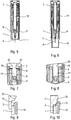
- the figure 7 illustrates a first variant embodiment of the injection lock.
- the injection lock is formed between the piston rod TP and a ring 60 fixed, in particular crimped, directly on the radial flange 9 of the syringe S.
- Said ring 60 comprises a radially internal projection 61 fixed to said rod TP piston by breakable bridges 63.
- the breaking strength of these breakable bridges 63 is greater than the triggering force of the stitching lock, that is to say the axial displacement of the reservoir S in the lower body 1, so that the stitching has before injection.
- the figure 8 illustrates another variant in which said radially internal projection 61 of crimping ring 60 cooperates before actuation with a groove 62 of the piston rod TP.
- the force required to disengage said projection 61 from said groove 62 is greater than the triggering force of the stitching lock, that is to say the axial displacement of the reservoir S in the lower body 1, so that the stitching has before injection.
- the figures 9 and 10 illustrate the triggering of the post-injection safety device, with the sleeve 10 which moves out of the lower body 1 towards its projected position.
- the sleeve 10 has an end 15 elastically deformable radially inwards. In the rest position, shown on figure 9 , this end 15 rests on a radial shoulder 3 of the lower body 1.
- the sleeve 10 is therefore blocked against any axial displacement towards its projected position relative to said lower body 1.
- the upper body 2 cooperates via a cam 25 with said end 15 of the sleeve, to deform it radially inwards, as visible on the figure 10 .
- the sleeve 10 is then no longer blocked, and it can move towards its projected position, for example under the effect of a suitable spring.
Landscapes
- Health & Medical Sciences (AREA)
- Engineering & Computer Science (AREA)
- Hematology (AREA)
- Anesthesiology (AREA)
- Biomedical Technology (AREA)
- Heart & Thoracic Surgery (AREA)
- Vascular Medicine (AREA)
- Life Sciences & Earth Sciences (AREA)
- Animal Behavior & Ethology (AREA)
- General Health & Medical Sciences (AREA)
- Public Health (AREA)
- Veterinary Medicine (AREA)
- Environmental & Geological Engineering (AREA)
- Infusion, Injection, And Reservoir Apparatuses (AREA)
Description
- La présente invention concerne un dispositif d'injection manuelle.
- Les dispositifs d'injection manuelle ont principalement pour but de réaliser la pénétration de l'aiguille dans le corps du patient ainsi que la protection de l'aiguille de la seringue avant, pendant et après l'injection. Par contre, l'injection dans le corps du patient du produit contenu dans la seringue est réalisée manuellement par l'utilisateur. Les dispositifs d'injection manuelle sont des dispositifs relativement complexes qui doivent répondre à un certain nombre d'exigences de contraintes pour être fiables. La robustesse du dispositif, sa maniabilité, et sa facilité d'utilisation pour l'utilisateur sont également des éléments importants. Par ailleurs, la plupart de ces dispositifs d'injection manuelle étant à usage unique, le coût de fabrication et d'assemblage est également un facteur dont il faut tenir compte.
- Il existe de nombreux dispositifs d'injection manuelle sur le marché, qui présentent toutefois tous un certain nombre d'inconvénients.
- Ainsi, il ne faut pas que l'utilisation du dispositif d'injection manuelle soit trop difficile, ce qui empêcherait des personnes faibles de l'utiliser. Il faut aussi éviter que l'injection ne commence avant que l'aiguille ait pénétré dans le corps du patient. De plus, afin d'éviter tout risque de blessures avant et après l'utilisation du dispositif, le dispositif d'injection manuelle doit comprendre un dispositif de sécurité aiguille qui évite que l'aiguille ne soit apparente avant et après l'utilisation du dispositif. Ce dispositif de sécurité doit évidemment également être fiable et ne pas se libérer trop facilement. Il doit aussi être fonctionnel même si l'utilisateur actionne mal le dispositif d'injection manuelle, par exemple s'il le retire trop tôt de son corps, avant la fin de l'injection.
- Les documents
WO2014150201 ,WO2011047298 ,WO2012045350 ,WO2006129196 ,WO2006111862 ,FR2884722 US5320609 ,EP2572741 etFR3019748 - La présente invention a pour but de fournir un dispositif d'injection manuelle qui ne reproduit pas les inconvénients susmentionnés, et qui permet de répondre aux différentes exigences et contraintes importantes pour une utilisation sûre et fiable du dispositif d'injection manuelle.
- La présente invention a notamment but de fournir un dispositif d'injection manuelle qui évite le risque que l'injection du produit ne débute avant que l'aiguille ait complètement pénétrée le site d'injection.
- La présente invention a aussi pour but de fournir un dispositif d'injection manuelle qui soit fiable d'utilisation, qui soit sûr et qui empêche tout risque de blessure, et qui soit simple et peu coûteux à fabriquer et à assembler.
- La présente invention a donc pour objet un dispositif d'injection manuelle comportant :
- un corps inférieur recevant un réservoir, ledit réservoir étant monté axialement déplaçable dans ledit corps inférieur et contenant du produit fluide à injecter, ledit réservoir comportant un piston et une aiguille,
- un corps supérieur monté axialement déplaçable par rapport audit corps inférieur lors de l'actionnement, ledit corps supérieur comportant une tige de piston coopérant avec ledit piston lors de l'injection pour le déplacer dans le réservoir,
- un manchon monté déplaçable par rapport audit corps inférieur entre une position de repos, dans laquelle ledit manchon est disposé à l'intérieur dudit corps inférieur, et une position projetée, dans laquelle ledit manchon est axialement déplacé hors dudit corps inférieur, ledit manchon étant bloqué dans sa position de repos avant actionnement du dispositif d'injection manuelle et étant sollicité automatiquement dans sa position projetée après injection,
- ladite tige de piston coopérant avec ledit réservoir, ou avec tout élément solidaire dudit réservoir, pour former une serrure d'injection, la force nécessaire pour déplacer axialement ledit réservoir dans ledit corps inférieur étant inférieure à la force nécessaire pour déclencher ladite serrure d'injection, de sorte que ledit piquage est réalisé avant ladite injection,
- Avantageusement, ladite tige de piston, avant actionnement, est reliée par des ponts sécables à ladite bague.
- En variante, ladite bague comporte une projection radialement interne coopérant, avant actionnement, avec une gorge de ladite tige de piston.
- Avantageusement, ledit manchon comporte une extrémité élastiquement déformable radialement vers l'intérieur, ladite extrémité reposant en position de repos sur un épaulement radial du corps inférieur, ledit corps supérieur coopérant en fin d'injection via une came avec ladite extrémité dudit manchon, pour déformer ladite extrémité radialement vers l'intérieur.
- Ces caractéristiques et avantages et d'autres de la présente invention apparaîtront plus clairement au cours de la description détaillée suivante, faite en référence aux dessins joints, donnés à titre d'exemples non limitatifs, et sur lesquels :
- la
figure 1 est une vue schématique en section transversale d'un dispositif d'injection manuelle selon un mode de réalisation avantageux, en position de repos avant piquage, - la
figure 2 est une vue similaire à celle de lafigure 1 , selon un autre angle de vue, - la
figure 3 est une vue similaire à celle de lafigure 2 , en fin de piquage, avant déclenchement de la serrure d'injection, - la
figure 4 est une vue similaire à celle de lafigure 3 , après déclenchement de la serrure d'injection, - la
figure 5 est une vue similaire à celle de lafigure 4 , en fin d'injection, - la
figure 6 est une vue similaire à celle de lafigure 5 , après déclenchement du dispositif de sécurité post-injection, - la
figure 7 est une vue de détail d'une première variante de réalisation de la serrure d'injection, - la
figure 8 est une vue de détail d'une seconde variante de réalisation de la serrure d'injection, et - les
figures 9 et 10 sont des vues schématiques de détail du déclenchement du dispositif de sécurité post-injection. - Le dispositif d'injection manuelle représenté sur les figures comporte un corps inférieur 1 et un corps supérieur 2, axialement déplaçable par rapport audit corps inférieur 1 lors de l'actionnement. Il est à noter que les corps inférieur 1 et supérieur 2 peuvent être réalisés de manière monobloc ou en plusieurs parties assemblées. De manière connue, ce corps inférieur 1 contient un réservoir S contenant le produit à injecter, une aiguille A fixée audit réservoir S à travers laquelle le produit est distribué et un piston P adapté à se déplacer dans ledit réservoir S pour réaliser cette injection. Le corps supérieur 2 comporte une tige de piston TP coopérant avec ledit piston P lors de l'injection pour le déplacer dans le réservoir S. L'aiguille A peut être protégée avant utilisation par un capuchon de protection. Le réservoir S peut typiquement être une seringue pré-remplie classique, pourvue d'une collerette radiale 9. Ledit réservoir S est mobile axialement dans ledit corps inférieur 1 pour réaliser le piquage, puis est fixe par rapport audit corps inférieur 1 lors de l'injection. Ladite tige de piston TP est fixe par rapport audit corps supérieur 2. Ainsi, lorsque le corps supérieur 2 coulisse axialement par rapport au corps inférieur 1, la tige de piston TP coulisse axialement par rapport au réservoir S.
- Avant actionnement, un manchon 10 de sécurité post-injection est disposé à l'intérieur du corps inférieur. Après l'injection, ledit manchon 10 est déplacé axialement hors du corps inférieur 1 dans une position projetée, dans laquelle il est disposé autour de l'aiguille A, pour éviter tout risque de blessure avec ladite aiguille A, formant ainsi un dispositif de sécurité post-injection. Le manchon 10 est avantageusement sollicité vers sa position projetée par un ressort, qui peut être de type quelconque. Avant actionnement, ledit manchon 10 est bloqué et empêché de se déplacer vers sa position projetée par des moyens de blocage qui sont libérés en fin d'injection.
- La tige de piston TP définit avec le réservoir S (ou avec tout élément solidaire dudit réservoir S, tel que par exemple un support de réservoir ou une bague encliquetée sur ledit réservoir) une serrure d'actionnement. Cette serrure comprend une serrure de piquage et une serrure d'injection.
- Selon l'invention, la serrure de piquage est actionnée avant la serrure d'injection, c'est à dire que la force axiale nécessaire pour déplacer axialement le réservoir S dans le corps inférieur 1 est inférieure à la force axiale nécessaire pour déclencher la serrure d'injection. Ainsi, lorsque l'utilisateur appuie le dispositif contre le site d'injection et appuie axialement sur le corps supérieur 2 pour le faire coulisser axialement par rapport au corps inférieur 1, c'est d'abord le réservoir S qui se déplace axialement à l'intérieur du corps inférieur 1 pour réaliser le piquage. La tige de piston TP ne se déplace axialement à l'intérieur du réservoir S qu'après que le piquage est terminé.
- Les
figures 1 à 6 illustrent un mode de réalisation avantageux et montrent différentes positions dans la séquence d'actionnement du dispositif d'injection manuelle. - En référence aux
figures 1 à 6 , l'utilisateur appuie l'extrémité inférieure 11 du corps inférieur 1 autour du site d'injection, et exerce une pression axiale sur le corps supérieur 2. La résistance au déclenchement de la serrure d'injection, qui sera décrite ultérieurement, étant supérieure à la résistance au déplacement axial du réservoir S dans ledit corps inférieur 1, c'est d'abord le réservoir S qui va coulisser axialement vers l'intérieur du corps inférieur 1. Ceci va permettre à l'aiguille A de pénétrer dans le site d'injection sous l'effet de ladite pression axiale de l'utilisateur. Ce n'est que lorsque le réservoir S atteint sa position piquée, en butée axiale dans le corps inférieur 1, empêchant ainsi tout déplacement axial supplémentaire dudit réservoir S, que la force d'actionnement ou pression axiale de l'utilisateur servira à déclencher la serrure d'injection. Après déclenchement de ladite serrure d'injection, le corps supérieur 2 et donc la tige de piston TP vont se déplacer axialement par rapport au réservoir S, pour déplacer le piston P dans le réservoir S et ainsi injecter le produit contenu dans le réservoir, à travers l'aiguille A, dans le site d'injection. En fin d'injection, lorsque l'utilisateur retire le dispositif d'injection manuelle du site d'injection, le manchon 10 est libéré des moyens de blocage et se déplace automatiquement, par exemple sous l'effet du ressort de rappel 5, vers sa position projetée, dans laquelle il se verrouille, pour éviter tout risque de blessure avec l'aiguille A, comme visible sur lafigure 6 . - La
figure 7 illustre une première variante de réalisation de la serrure d'injection. Dans cette variante, la serrure d'injection est formée entre la tige de piston TP et une bague 60 fixée, notamment sertie, directement sur la collerette radiale 9 de la seringue S. Ladite bague 60 comporte une projection radialement interne 61 fixée à ladite tige de piston TP par des ponts sécables 63. La résistance à la rupture de ces ponts sécables 63 est supérieure à la force de déclenchement de la serrure de piquage, c'est-à-dire au déplacement axial du réservoir S dans le corps inférieur 1, de sorte que le piquage a lieu avant l'injection. - La
figure 8 illustre une autre variante dans laquelle ladite projection radialement interne 61 de bague de sertissage 60 coopère avant actionnement avec une gorge 62 de la tige de piston TP. La force nécessaire pour désengager ladite projection 61 de ladite gorge 62 est supérieure à la force de déclenchement de la serrure de piquage, c'est-à-dire au déplacement axial du réservoir S dans le corps inférieur 1, de sorte que le piquage a lieu avant l'injection. - D'autres variantes de réalisation de la serrure de piquage et/ou de la serrure d'injection sont aussi envisageables.
- Les
figures 9 et 10 illustrent le déclenchement du dispositif de sécurité post-injection, avec le manchon 10 qui se déplace hors du corps inférieur 1 vers sa position projetée. Le manchon 10 comporte une extrémité 15 élastiquement déformable radialement vers l'intérieur. En position de repos, représentée sur lafigure 9 , cette extrémité 15 repose sur un épaulement radial 3 du corps inférieur 1. Le manchon 10 est donc bloqué contre tout déplacement axial vers sa position projetée par rapport audit corps inférieur 1. En fin d'injection, le corps supérieur 2 vient coopérer via une came 25 avec ladite extrémité 15 du manchon, pour la déformer radialement vers l'intérieur, comme visible sur lafigure 10 . Le manchon 10 n'est alors plus bloqué, et il peut se déplacer vers sa position projetée, par exemple sous l'effet d'un ressort approprié. - Bien que la présente invention ait été décrite en référence à des modes et variantes de réalisation avantageux, il est entendu que l'homme du métier peut y apporter diverses modifications sans sortir du cadre de la présente invention tel que défini par les revendications annexées.
Claims (4)
- Dispositif d'injection manuelle comportant :- un corps inférieur (1) recevant un réservoir (S), ledit réservoir étant monté axialement déplaçable dans ledit corps inférieur (1) et contenant du produit fluide à injecter, ledit réservoir (S) comportant un piston (P) et une aiguille (A),- un corps supérieur (2) monté axialement déplaçable par rapport audit corps inférieur (1) lors de l'actionnement, ledit corps supérieur (2) comportant une tige de piston (TP) coopérant avec ledit piston (P) lors de l'injection pour le déplacer dans le réservoir (S),- un manchon (10) monté déplaçable par rapport audit corps inférieur (1) entre une position de repos, dans laquelle ledit manchon (10) est disposé à l'intérieur dudit corps inférieur (1), et une position projetée, dans laquelle ledit manchon (10) est axialement déplacé hors dudit corps inférieur (1), ledit manchon (10) étant bloqué dans sa position de repos avant actionnement du dispositif d'injection manuelle et étant sollicité automatiquement dans sa position projetée après injection,caractérisé en ce qu'avant actionnement, ladite tige de piston (TP) est reliée à une bague (60) fixée, notamment sertie, sur une collerette radiale (9) dudit réservoir (S) pour former une serrure d'injection, la force nécessaire pour déplacer axialement ledit réservoir (S) dans ledit corps inférieur (1) étant inférieure à la force nécessaire pour déclencher ladite serrure d'injection, de sorte que ledit piquage est réalisé avant ladite injection.
- Dispositif d'injection manuelle selon la revendication 1, dans lequel ladite tige de piston (TP), avant actionnement, est reliée par des ponts sécables (63) à ladite bague (60).
- Dispositif d'injection manuelle selon la revendication 1, dans lequel ladite bague (60) comporte une projection radialement interne (61) coopérant, avant actionnement, avec une gorge (62) de ladite tige de piston (TP).
- Dispositif d'injection manuelle selon l'une quelconque des revendications précédentes, dans lequel ledit manchon (10) comporte une extrémité (15) élastiquement déformable radialement vers l'intérieur, ladite extrémité (15) reposant en position de repos sur un épaulement radial (3) du corps inférieur (1), ledit corps supérieur (2) coopérant en fin d'injection via une came (25) avec ladite extrémité (15) dudit manchon (10), pour déformer ladite extrémité (15) radialement vers l'intérieur.
Applications Claiming Priority (2)
| Application Number | Priority Date | Filing Date | Title |
|---|---|---|---|
| FR1659549A FR3056915B1 (fr) | 2016-10-04 | 2016-10-04 | Dispositif d'injection manuelle. |
| PCT/FR2017/052698 WO2018065714A1 (fr) | 2016-10-04 | 2017-10-02 | Dispositif d'injection manuelle. |
Publications (2)
| Publication Number | Publication Date |
|---|---|
| EP3522955A1 EP3522955A1 (fr) | 2019-08-14 |
| EP3522955B1 true EP3522955B1 (fr) | 2020-08-12 |
Family
ID=57796499
Family Applications (1)
| Application Number | Title | Priority Date | Filing Date |
|---|---|---|---|
| EP17793988.1A Active EP3522955B1 (fr) | 2016-10-04 | 2017-10-02 | Dispositif d'injection manuelle. |
Country Status (6)
| Country | Link |
|---|---|
| US (1) | US10898657B2 (fr) |
| EP (1) | EP3522955B1 (fr) |
| JP (1) | JP6957628B2 (fr) |
| CN (1) | CN109789275B (fr) |
| FR (1) | FR3056915B1 (fr) |
| WO (1) | WO2018065714A1 (fr) |
Families Citing this family (1)
| Publication number | Priority date | Publication date | Assignee | Title |
|---|---|---|---|---|
| JP7525955B2 (ja) | 2021-04-08 | 2024-07-31 | ラブ ライフサイエンシズ エルエルシー | プレフィルドシリンジ安全デバイスおよび注射器 |
Family Cites Families (15)
| Publication number | Priority date | Publication date | Assignee | Title |
|---|---|---|---|---|
| US5320609A (en) * | 1992-12-07 | 1994-06-14 | Habley Medical Technology Corporation | Automatic pharmaceutical dispensing syringe |
| FR2861598B1 (fr) * | 2003-10-29 | 2006-06-16 | Plastef Investissements | Dispositif d'injection securise pour une seringue |
| US20050101919A1 (en) * | 2003-11-07 | 2005-05-12 | Lennart Brunnberg | Device for an injector |
| ES2677022T3 (es) * | 2005-04-20 | 2018-07-27 | Becton Dickinson France | Conjunto de inyección y dispositivo de asistencia de inyección |
| FR2884721A1 (fr) * | 2005-04-20 | 2006-10-27 | Becton Dickinson France Soc Pa | Ensemble d'injection et dispositif d'assistance a l'injection |
| FR2884722A1 (fr) * | 2005-04-20 | 2006-10-27 | Becton Dickinson France Soc Pa | Ensemble d'injection et dispositif d'assistance |
| EP2211945B1 (fr) * | 2007-09-25 | 2017-09-20 | Becton Dickinson France | Injecteur automatique inséré dans un support externe |
| TWI393578B (zh) * | 2009-07-07 | 2013-04-21 | Shl Group Ab | 注射裝置 |
| WO2011047298A2 (fr) | 2009-10-16 | 2011-04-21 | Centocor Ortho Biotech Inc. | Dispositif d'administration de médicament activé par la paume |
| EP2624882B1 (fr) * | 2010-10-06 | 2021-04-28 | Ypsomed AG | Mécanisme de verrouillage et de retenue pour le protecteur d'aiguille d'un dispositif d'injection |
| EP2661293B1 (fr) * | 2011-01-04 | 2019-01-23 | Sanofi-Aventis Deutschland GmbH | Dispositif de sécurité pour seringue pré-remplie et dispositif d'injection |
| EP2572741A1 (fr) * | 2011-09-23 | 2013-03-27 | Sanofi-Aventis Deutschland GmbH | Dispositif d'administration de médicament et mécanisme d'actionnement pour un dispositif d'administration de médicament |
| US9802005B2 (en) * | 2012-10-03 | 2017-10-31 | Carebay Europe Ltd | Medicament delivery device |
| JP6445514B2 (ja) * | 2013-03-15 | 2018-12-26 | ヤンセン バイオテツク,インコーポレーテツド | 手のひら作動式薬剤送達装置 |
| FR3019748A1 (fr) * | 2014-04-11 | 2015-10-16 | Aptar France Sas | Autoinjecteur |
-
2016
- 2016-10-04 FR FR1659549A patent/FR3056915B1/fr active Active
-
2017
- 2017-10-02 WO PCT/FR2017/052698 patent/WO2018065714A1/fr not_active Ceased
- 2017-10-02 JP JP2019538735A patent/JP6957628B2/ja active Active
- 2017-10-02 CN CN201780061681.4A patent/CN109789275B/zh active Active
- 2017-10-02 US US16/339,196 patent/US10898657B2/en active Active
- 2017-10-02 EP EP17793988.1A patent/EP3522955B1/fr active Active
Non-Patent Citations (1)
| Title |
|---|
| None * |
Also Published As
| Publication number | Publication date |
|---|---|
| WO2018065714A1 (fr) | 2018-04-12 |
| US20190240422A1 (en) | 2019-08-08 |
| EP3522955A1 (fr) | 2019-08-14 |
| JP6957628B2 (ja) | 2021-11-02 |
| JP2019529055A (ja) | 2019-10-17 |
| CN109789275A (zh) | 2019-05-21 |
| FR3056915B1 (fr) | 2021-12-17 |
| CN109789275B (zh) | 2021-04-27 |
| FR3056915A1 (fr) | 2018-04-06 |
| US10898657B2 (en) | 2021-01-26 |
Similar Documents
| Publication | Publication Date | Title |
|---|---|---|
| EP3522957B1 (fr) | Dispositif d'injection manuelle | |
| EP2854905B1 (fr) | Autoinjecteur. | |
| EP3074064B1 (fr) | Autoinjecteur | |
| EP1673121B1 (fr) | Dispositif de protection d`un appareil d`injection | |
| EP3302645B1 (fr) | Autoinjecteur | |
| EP3352819B1 (fr) | Autoinjecteur | |
| EP3129085B1 (fr) | Autoinjecteur | |
| EP1485153B1 (fr) | Dispositif de protection d aiguille destine a une seringue, et dispositif d injection comprenant une seringue et ce disp ositif de protection | |
| EP2854899B1 (fr) | Autoinjecteur | |
| WO2015155484A1 (fr) | Autoinjecteur | |
| EP2854904B1 (fr) | Autoinjecteur | |
| FR2922112A1 (fr) | Dispositif de securite pour une seringue d'injection de liquide et ensemble a seringue comprenant ce dispositif | |
| FR2930162A1 (fr) | Ensemble de protection d'aiguille comportant un element de verrouillage. | |
| FR2930161A1 (fr) | Ensemble de protection d'aiguille comportant un element de verrouillage mobile radialement. | |
| EP2854901B1 (fr) | Autoinjecteur avec un retardateur ayant un train épicycloidal pour retarder la retraction de l'aiguille | |
| EP3308814A1 (fr) | Autoinjecteur | |
| FR3036965A1 (fr) | Autoinjecteur | |
| EP3374006B1 (fr) | Autoinjecteur ayant une fenêtre mediane ayant une extremite en triangle | |
| EP1356839B9 (fr) | Ensemble de seringue d'injection de liquide et fourreau pour cet ensemble | |
| WO2018065714A1 (fr) | Dispositif d'injection manuelle. | |
| FR2905873A1 (fr) | Dispositif d'injection prevenant le recul du piston lors du deploiement du systeme de securite | |
| EP3831431B1 (fr) | Dispositif d'injection de produit fluide | |
| EP3946523A1 (fr) | Dispositif d'injection de produit fluide |
Legal Events
| Date | Code | Title | Description |
|---|---|---|---|
| STAA | Information on the status of an ep patent application or granted ep patent |
Free format text: STATUS: UNKNOWN |
|
| STAA | Information on the status of an ep patent application or granted ep patent |
Free format text: STATUS: THE INTERNATIONAL PUBLICATION HAS BEEN MADE |
|
| PUAI | Public reference made under article 153(3) epc to a published international application that has entered the european phase |
Free format text: ORIGINAL CODE: 0009012 |
|
| STAA | Information on the status of an ep patent application or granted ep patent |
Free format text: STATUS: REQUEST FOR EXAMINATION WAS MADE |
|
| 17P | Request for examination filed |
Effective date: 20190430 |
|
| AK | Designated contracting states |
Kind code of ref document: A1 Designated state(s): AL AT BE BG CH CY CZ DE DK EE ES FI FR GB GR HR HU IE IS IT LI LT LU LV MC MK MT NL NO PL PT RO RS SE SI SK SM TR |
|
| AX | Request for extension of the european patent |
Extension state: BA ME |
|
| DAV | Request for validation of the european patent (deleted) | ||
| DAX | Request for extension of the european patent (deleted) | ||
| GRAP | Despatch of communication of intention to grant a patent |
Free format text: ORIGINAL CODE: EPIDOSNIGR1 |
|
| STAA | Information on the status of an ep patent application or granted ep patent |
Free format text: STATUS: GRANT OF PATENT IS INTENDED |
|
| INTG | Intention to grant announced |
Effective date: 20200310 |
|
| GRAS | Grant fee paid |
Free format text: ORIGINAL CODE: EPIDOSNIGR3 |
|
| GRAA | (expected) grant |
Free format text: ORIGINAL CODE: 0009210 |
|
| STAA | Information on the status of an ep patent application or granted ep patent |
Free format text: STATUS: THE PATENT HAS BEEN GRANTED |
|
| AK | Designated contracting states |
Kind code of ref document: B1 Designated state(s): AL AT BE BG CH CY CZ DE DK EE ES FI FR GB GR HR HU IE IS IT LI LT LU LV MC MK MT NL NO PL PT RO RS SE SI SK SM TR |
|
| REG | Reference to a national code |
Ref country code: CH Ref legal event code: EP |
|
| REG | Reference to a national code |
Ref country code: DE Ref legal event code: R096 Ref document number: 602017021652 Country of ref document: DE |
|
| REG | Reference to a national code |
Ref country code: IE Ref legal event code: FG4D Free format text: LANGUAGE OF EP DOCUMENT: FRENCH |
|
| REG | Reference to a national code |
Ref country code: AT Ref legal event code: REF Ref document number: 1300906 Country of ref document: AT Kind code of ref document: T Effective date: 20200915 |
|
| REG | Reference to a national code |
Ref country code: LT Ref legal event code: MG4D |
|
| REG | Reference to a national code |
Ref country code: NL Ref legal event code: MP Effective date: 20200812 |
|
| PG25 | Lapsed in a contracting state [announced via postgrant information from national office to epo] |
Ref country code: BG Free format text: LAPSE BECAUSE OF FAILURE TO SUBMIT A TRANSLATION OF THE DESCRIPTION OR TO PAY THE FEE WITHIN THE PRESCRIBED TIME-LIMIT Effective date: 20201112 Ref country code: NO Free format text: LAPSE BECAUSE OF FAILURE TO SUBMIT A TRANSLATION OF THE DESCRIPTION OR TO PAY THE FEE WITHIN THE PRESCRIBED TIME-LIMIT Effective date: 20201112 Ref country code: SE Free format text: LAPSE BECAUSE OF FAILURE TO SUBMIT A TRANSLATION OF THE DESCRIPTION OR TO PAY THE FEE WITHIN THE PRESCRIBED TIME-LIMIT Effective date: 20200812 Ref country code: FI Free format text: LAPSE BECAUSE OF FAILURE TO SUBMIT A TRANSLATION OF THE DESCRIPTION OR TO PAY THE FEE WITHIN THE PRESCRIBED TIME-LIMIT Effective date: 20200812 Ref country code: GR Free format text: LAPSE BECAUSE OF FAILURE TO SUBMIT A TRANSLATION OF THE DESCRIPTION OR TO PAY THE FEE WITHIN THE PRESCRIBED TIME-LIMIT Effective date: 20201113 Ref country code: LT Free format text: LAPSE BECAUSE OF FAILURE TO SUBMIT A TRANSLATION OF THE DESCRIPTION OR TO PAY THE FEE WITHIN THE PRESCRIBED TIME-LIMIT Effective date: 20200812 Ref country code: HR Free format text: LAPSE BECAUSE OF FAILURE TO SUBMIT A TRANSLATION OF THE DESCRIPTION OR TO PAY THE FEE WITHIN THE PRESCRIBED TIME-LIMIT Effective date: 20200812 |
|
| REG | Reference to a national code |
Ref country code: AT Ref legal event code: MK05 Ref document number: 1300906 Country of ref document: AT Kind code of ref document: T Effective date: 20200812 |
|
| PG25 | Lapsed in a contracting state [announced via postgrant information from national office to epo] |
Ref country code: LV Free format text: LAPSE BECAUSE OF FAILURE TO SUBMIT A TRANSLATION OF THE DESCRIPTION OR TO PAY THE FEE WITHIN THE PRESCRIBED TIME-LIMIT Effective date: 20200812 Ref country code: NL Free format text: LAPSE BECAUSE OF FAILURE TO SUBMIT A TRANSLATION OF THE DESCRIPTION OR TO PAY THE FEE WITHIN THE PRESCRIBED TIME-LIMIT Effective date: 20200812 Ref country code: PL Free format text: LAPSE BECAUSE OF FAILURE TO SUBMIT A TRANSLATION OF THE DESCRIPTION OR TO PAY THE FEE WITHIN THE PRESCRIBED TIME-LIMIT Effective date: 20200812 Ref country code: RS Free format text: LAPSE BECAUSE OF FAILURE TO SUBMIT A TRANSLATION OF THE DESCRIPTION OR TO PAY THE FEE WITHIN THE PRESCRIBED TIME-LIMIT Effective date: 20200812 Ref country code: IS Free format text: LAPSE BECAUSE OF FAILURE TO SUBMIT A TRANSLATION OF THE DESCRIPTION OR TO PAY THE FEE WITHIN THE PRESCRIBED TIME-LIMIT Effective date: 20201212 |
|
| PG25 | Lapsed in a contracting state [announced via postgrant information from national office to epo] |
Ref country code: CZ Free format text: LAPSE BECAUSE OF FAILURE TO SUBMIT A TRANSLATION OF THE DESCRIPTION OR TO PAY THE FEE WITHIN THE PRESCRIBED TIME-LIMIT Effective date: 20200812 Ref country code: DK Free format text: LAPSE BECAUSE OF FAILURE TO SUBMIT A TRANSLATION OF THE DESCRIPTION OR TO PAY THE FEE WITHIN THE PRESCRIBED TIME-LIMIT Effective date: 20200812 Ref country code: RO Free format text: LAPSE BECAUSE OF FAILURE TO SUBMIT A TRANSLATION OF THE DESCRIPTION OR TO PAY THE FEE WITHIN THE PRESCRIBED TIME-LIMIT Effective date: 20200812 Ref country code: EE Free format text: LAPSE BECAUSE OF FAILURE TO SUBMIT A TRANSLATION OF THE DESCRIPTION OR TO PAY THE FEE WITHIN THE PRESCRIBED TIME-LIMIT Effective date: 20200812 Ref country code: SM Free format text: LAPSE BECAUSE OF FAILURE TO SUBMIT A TRANSLATION OF THE DESCRIPTION OR TO PAY THE FEE WITHIN THE PRESCRIBED TIME-LIMIT Effective date: 20200812 |
|
| REG | Reference to a national code |
Ref country code: DE Ref legal event code: R097 Ref document number: 602017021652 Country of ref document: DE |
|
| PG25 | Lapsed in a contracting state [announced via postgrant information from national office to epo] |
Ref country code: AL Free format text: LAPSE BECAUSE OF FAILURE TO SUBMIT A TRANSLATION OF THE DESCRIPTION OR TO PAY THE FEE WITHIN THE PRESCRIBED TIME-LIMIT Effective date: 20200812 Ref country code: AT Free format text: LAPSE BECAUSE OF FAILURE TO SUBMIT A TRANSLATION OF THE DESCRIPTION OR TO PAY THE FEE WITHIN THE PRESCRIBED TIME-LIMIT Effective date: 20200812 Ref country code: ES Free format text: LAPSE BECAUSE OF FAILURE TO SUBMIT A TRANSLATION OF THE DESCRIPTION OR TO PAY THE FEE WITHIN THE PRESCRIBED TIME-LIMIT Effective date: 20200812 |
|
| REG | Reference to a national code |
Ref country code: CH Ref legal event code: PL |
|
| PLBE | No opposition filed within time limit |
Free format text: ORIGINAL CODE: 0009261 |
|
| STAA | Information on the status of an ep patent application or granted ep patent |
Free format text: STATUS: NO OPPOSITION FILED WITHIN TIME LIMIT |
|
| PG25 | Lapsed in a contracting state [announced via postgrant information from national office to epo] |
Ref country code: MC Free format text: LAPSE BECAUSE OF FAILURE TO SUBMIT A TRANSLATION OF THE DESCRIPTION OR TO PAY THE FEE WITHIN THE PRESCRIBED TIME-LIMIT Effective date: 20200812 Ref country code: LU Free format text: LAPSE BECAUSE OF NON-PAYMENT OF DUE FEES Effective date: 20201002 Ref country code: SK Free format text: LAPSE BECAUSE OF FAILURE TO SUBMIT A TRANSLATION OF THE DESCRIPTION OR TO PAY THE FEE WITHIN THE PRESCRIBED TIME-LIMIT Effective date: 20200812 |
|
| REG | Reference to a national code |
Ref country code: BE Ref legal event code: MM Effective date: 20201031 |
|
| 26N | No opposition filed |
Effective date: 20210514 |
|
| PG25 | Lapsed in a contracting state [announced via postgrant information from national office to epo] |
Ref country code: CH Free format text: LAPSE BECAUSE OF NON-PAYMENT OF DUE FEES Effective date: 20201031 Ref country code: BE Free format text: LAPSE BECAUSE OF NON-PAYMENT OF DUE FEES Effective date: 20201031 Ref country code: SI Free format text: LAPSE BECAUSE OF FAILURE TO SUBMIT A TRANSLATION OF THE DESCRIPTION OR TO PAY THE FEE WITHIN THE PRESCRIBED TIME-LIMIT Effective date: 20200812 Ref country code: LI Free format text: LAPSE BECAUSE OF NON-PAYMENT OF DUE FEES Effective date: 20201031 |
|
| PG25 | Lapsed in a contracting state [announced via postgrant information from national office to epo] |
Ref country code: IE Free format text: LAPSE BECAUSE OF NON-PAYMENT OF DUE FEES Effective date: 20201002 |
|
| PG25 | Lapsed in a contracting state [announced via postgrant information from national office to epo] |
Ref country code: TR Free format text: LAPSE BECAUSE OF FAILURE TO SUBMIT A TRANSLATION OF THE DESCRIPTION OR TO PAY THE FEE WITHIN THE PRESCRIBED TIME-LIMIT Effective date: 20200812 Ref country code: MT Free format text: LAPSE BECAUSE OF FAILURE TO SUBMIT A TRANSLATION OF THE DESCRIPTION OR TO PAY THE FEE WITHIN THE PRESCRIBED TIME-LIMIT Effective date: 20200812 Ref country code: CY Free format text: LAPSE BECAUSE OF FAILURE TO SUBMIT A TRANSLATION OF THE DESCRIPTION OR TO PAY THE FEE WITHIN THE PRESCRIBED TIME-LIMIT Effective date: 20200812 |
|
| PG25 | Lapsed in a contracting state [announced via postgrant information from national office to epo] |
Ref country code: MK Free format text: LAPSE BECAUSE OF FAILURE TO SUBMIT A TRANSLATION OF THE DESCRIPTION OR TO PAY THE FEE WITHIN THE PRESCRIBED TIME-LIMIT Effective date: 20200812 |
|
| PG25 | Lapsed in a contracting state [announced via postgrant information from national office to epo] |
Ref country code: PT Free format text: LAPSE BECAUSE OF FAILURE TO SUBMIT A TRANSLATION OF THE DESCRIPTION OR TO PAY THE FEE WITHIN THE PRESCRIBED TIME-LIMIT Effective date: 20200812 |
|
| P01 | Opt-out of the competence of the unified patent court (upc) registered |
Effective date: 20230526 |
|
| PGFP | Annual fee paid to national office [announced via postgrant information from national office to epo] |
Ref country code: DE Payment date: 20251015 Year of fee payment: 9 |
|
| PGFP | Annual fee paid to national office [announced via postgrant information from national office to epo] |
Ref country code: GB Payment date: 20251023 Year of fee payment: 9 |
|
| PGFP | Annual fee paid to national office [announced via postgrant information from national office to epo] |
Ref country code: IT Payment date: 20251007 Year of fee payment: 9 |
|
| PGFP | Annual fee paid to national office [announced via postgrant information from national office to epo] |
Ref country code: FR Payment date: 20251029 Year of fee payment: 9 |