EP3522368A1 - Autonomous reconfiguration of a multi-redundant actuator control system - Google Patents
Autonomous reconfiguration of a multi-redundant actuator control system Download PDFInfo
- Publication number
- EP3522368A1 EP3522368A1 EP19154772.8A EP19154772A EP3522368A1 EP 3522368 A1 EP3522368 A1 EP 3522368A1 EP 19154772 A EP19154772 A EP 19154772A EP 3522368 A1 EP3522368 A1 EP 3522368A1
- Authority
- EP
- European Patent Office
- Prior art keywords
- mode
- response
- master
- electromechanical
- flight control
- Prior art date
- Legal status (The legal status is an assumption and is not a legal conclusion. Google has not performed a legal analysis and makes no representation as to the accuracy of the status listed.)
- Granted
Links
Images




Classifications
-
- B—PERFORMING OPERATIONS; TRANSPORTING
- B64—AIRCRAFT; AVIATION; COSMONAUTICS
- B64C—AEROPLANES; HELICOPTERS
- B64C13/00—Control systems or transmitting systems for actuating flying-control surfaces, lift-increasing flaps, air brakes, or spoilers
- B64C13/24—Transmitting means
- B64C13/38—Transmitting means with power amplification
- B64C13/50—Transmitting means with power amplification using electrical energy
- B64C13/503—Fly-by-Wire
-
- B—PERFORMING OPERATIONS; TRANSPORTING
- B64—AIRCRAFT; AVIATION; COSMONAUTICS
- B64C—AEROPLANES; HELICOPTERS
- B64C27/00—Rotorcraft; Rotors peculiar thereto
- B64C27/54—Mechanisms for controlling blade adjustment or movement relative to rotor head, e.g. lag-lead movement
- B64C27/56—Mechanisms for controlling blade adjustment or movement relative to rotor head, e.g. lag-lead movement characterised by the control initiating means, e.g. manually actuated
- B64C27/57—Mechanisms for controlling blade adjustment or movement relative to rotor head, e.g. lag-lead movement characterised by the control initiating means, e.g. manually actuated automatic or condition responsive, e.g. responsive to rotor speed, torque or thrust
-
- G—PHYSICS
- G05—CONTROLLING; REGULATING
- G05D—SYSTEMS FOR CONTROLLING OR REGULATING NON-ELECTRIC VARIABLES
- G05D1/00—Control of position, course, altitude or attitude of land, water, air or space vehicles, e.g. using automatic pilots
- G05D1/0055—Control of position, course, altitude or attitude of land, water, air or space vehicles, e.g. using automatic pilots with safety arrangements
- G05D1/0077—Control of position, course, altitude or attitude of land, water, air or space vehicles, e.g. using automatic pilots with safety arrangements using redundant signals or controls
-
- H—ELECTRICITY
- H02—GENERATION; CONVERSION OR DISTRIBUTION OF ELECTRIC POWER
- H02P—CONTROL OR REGULATION OF ELECTRIC MOTORS, ELECTRIC GENERATORS OR DYNAMO-ELECTRIC CONVERTERS; CONTROLLING TRANSFORMERS, REACTORS OR CHOKE COILS
- H02P29/00—Arrangements for regulating or controlling electric motors, appropriate for both AC and DC motors
- H02P29/02—Providing protection against overload without automatic interruption of supply
- H02P29/024—Detecting a fault condition, e.g. short circuit, locked rotor, open circuit or loss of load
- H02P29/0241—Detecting a fault condition, e.g. short circuit, locked rotor, open circuit or loss of load the fault being an overvoltage
Definitions
- the present disclosure relates to actuators, and more particularly to autonomous reconfiguration of a multi-redundant actuator control system.
- Vehicles like aircraft commonly include fly-by-wire flight control systems. Such systems typically include a plurality of actuators that move various flight control surfaces as commanded by a plurality of flight control computers. In safety critical aircraft flight control systems, typically at least triplex redundancy is required so that in case any one, or two of the command paths fail, the aircraft will remain under control.
- Modern actuators including a plurality of smart actuators, do not have the ability to operate autonomously. The "smartness" of the actuator is typically limited to basic servo position loop closure and some minimal built-in test. These modern smart actuators are not always capable of independently tolerating system faults and command outages (that could be caused by flight control computer resets, for example). Primary responsibility for detecting flight control system failures (including electromechanical motor failures) and subsequent reconfiguration to accommodate said failures has been relegated to the flight control computers.
- a fly-by-wire system in one aspect, includes an electromechanical actuator which includes a plurality of electromechanical motors. Each of the plurality of electromechanical motors is configured and operable to exchange operating status information with the other redundant electromechanical motors within the actuator. Also, each one of the plurality of electromechanical actuators is configured and operable to automatically configure itself for optimal mode of operation based on the received operating status information of at least one of the other electromechanical motors.
- the fly-by-wire system further includes a flight control computer operatively connected to the plurality of electromechanical motors within the actuator.
- a method for autonomously reconfiguring a multi-redundant actuator control system includes exchanging operating status information between a plurality of electromechanical motors within an electromechanical actuator and a flight control computer.
- the flight control computer is operatively connected to the plurality of electromechanical motors.
- Each of the plurality of electromechanical motors is automatically configured for optimal mode of operation based on the exchanged operating status information.
- Implementation of the techniques, blocks, steps and means described below may be done in various ways. For example, these techniques, blocks, steps and means may be implemented in hardware, software, or a combination thereof.
- the processing units may be implemented within one or more application specific integrated circuits (ASICs), digital signal processors (DSPs), digital signal processing devices (DSPDs), programmable logic devices (PLDs), field-programmable gate arrays (FPGAs), soft core processors, hard core processors, controllers, micro-controllers, microprocessors, other electronic units designed to perform the functions described above, and/or a combination thereof.
- ASICs application specific integrated circuits
- DSPs digital signal processors
- DSPDs digital signal processing devices
- PLDs programmable logic devices
- FPGAs field-programmable gate arrays
- Soft core processors hard core processors
- controllers micro-controllers
- microprocessors other electronic units designed to perform the functions described above, and/or a combination thereof.
- Software can be used instead of or
- the term "software” is meant to be synonymous with any code or program that can be in a processor of a host computer, regardless of whether the implementation is in hardware, firmware or as a software computer product available on a disc, a memory storage device, or for download from a remote machine.
- the embodiments described herein include such software to implement the equations, relationships and algorithms described below.
- One skilled in the art will appreciate further features and advantages of the invention based on the below-described embodiments. Accordingly, the invention is not to be limited by what has been particularly shown and described, except as indicated by the appended claims.
- a computer system component may constitute a "module” that is configured and operates to perform certain operations as described herein below.
- module should be understood to encompass a tangible entity, be that an entity that is physically constructed, permanently configured (e.g., hardwired) or temporarily configured (e.g. programmed) to operate in a certain manner and to perform certain operations described herein.
- Embodiments of the present invention are directed to a multi-redundant actuator. Behaviors that characterize the operational mode of the vehicle are associated with the actuators.
- a complete fly-by-wire flight control system typically controls multiple independent surfaces (for example, left and right ailerons).
- the system includes independent actuators for each surface.
- Multiple electromechanical motors may drive a single actuator (redundant drive mechanism). More specifically, the electromechanical motors, operating in conjunction with one another, drive the specific flight surface they are tasked with driving.
- multiple electromechanical motors that are driving one flight control surface interact with each other and autonomously configure themselves based on current operating conditions.
- Each of the actuators contains control logic that monitors inputs and fault status and properly configures all the redundant electromechanical motors to the optimal control state (mode of operation).
- the redundant control electromechanical motors communicate with each other to determine which one is in control (master mode) and which ones slave to the master (slave mode).
- embodiments of the present invention provide the redundant actuator capable of self-configuring autonomously from a command source.
- the command source is typically a flight control computer operable in a flight state and a ground state.
- the redundant actuator system is configured to control performance of the redundant suite of electromechanical motors prior to commands being available from the command source.
- FIG. 1 a partial view of an exemplary embodiment of an aircraft, here, an exemplary embodiment of an aircraft as a vertical takeoff and landing (VTOL) aircraft in accordance with the disclosure is shown in FIG. 1 and is designated generally by reference character 100.
- FIGS. 2-3 Other embodiments of aircraft in accordance with the disclosure, or aspects thereof, are provided in FIGS. 2-3 , as will be described.
- the systems and methods described herein provide for increased reliability multi-redundant actuators that can be used in fly-by-wire systems, while providing an ability to operate autonomously as compared with traditional actuator systems.
- VTOL aircraft 100 includes a main rotor system 102 and tail rotor system 104 supported by an airframe 106.
- Airframe 106 includes a gearbox 108 interconnecting an engine 110 with main rotor system 102 and tail rotor system 104.
- Main rotor system 102 is operatively connected to a swash plate 112.
- Swash plate 112 is operatively connected to hydraulic systems 114.
- VTOL aircraft 100 includes linear actuators 116, e.g. electromechanical actuators, operatively connected to the hydraulic systems 114, for example, a mechanical hydraulic servoactuator.
- VTOL aircraft configuration is illustrated and described in the disclosed embodiment, other configurations and/or machines, such as fixed wing aircraft, high speed compound rotary wing aircraft with supplemental translational thrust systems, dual contra-rotating, coaxial rotor system aircraft, turbo-props, tilt-rotors and tilt-wing aircraft, will also benefit from the present invention.
- System 118 includes a flight control computer 120 operatively connected to each of electromechanical motors 306. Each actuator 116 of system 118 is operatively connected to a respective one of hydraulic systems 114.
- System 118 includes a flight control surface 122 of a rotorcraft, e.g. VTOL aircraft 100, operatively connected to at least one of three hydraulic systems 114 through swash plate 112.
- actuator 116 includes a housing 202.
- Housing 202 includes a connector side 204 and a forcer rod side 206.
- Housing connector side 204 includes electromechanical motor power connectors 208 and signal connectors 210.
- Electromechanical motor power connectors 208 are operatively connected between an electromechanical motor drive 308, schematically shown in FIG. 3 , and respective electromechanical motors 306, described below, to operatively connect electromechanical motors 306 to motor drive 308.
- Actuator 116 includes a plurality of linear variable differential transformers (LVDT) 302, e.g. a position sensor, to measure the absolute displacement of electromechanical motors 306.
- Signal connectors 210 operatively connect respective LVDTs 302 to flight control computer 120.
- Signal connectors 210 receive actuator position signals from each LVDT 302 and send them to flight control computer 120, which compares the true position of actuator 116 to the commanded position from the pilot.
- LVDT linear variable differential transformers
- signal connectors 210 each correspond to a respective LVDT 302.
- Each LVDT 302 is in electrical communication with flight control computer 120 through signal connectors 210 to convey the position of LVDTs 302 and carriage 304.
- the position of carriage 304 corresponds to a respective position of each one of electromechanical motors 306.
- actuator controller and flight control computer 120 can appropriately adjust the power sent from electromechanical motor drives 308 to electromechanical motors 306 through motor power connectors 208 in order to achieve a desired position of carriage 304 along the longitudinal axis of actuator 116.
- the desired position of carriage 304 will depend on the input from the pilot or other control system.
- actuator 116 segregates three motor power connectors 208 and the three signal connectors 210, providing true redundancy between the systems, reducing the probability of failure due to a connector shorting out, or getting wet and losing connectivity.
- FIGS. 4 , 5A-5F illustrate various states and transitions supported by the disclosed multi-redundant actuator system.
- the electromechanical motor may assume one of the following states/modes: Init 402, Hold 404, Standby 406, Failsafe 408, Normal Master 410 and Normal Slave 412.
- Init 402 Hold 404
- Standby 406 Failsafe 408
- Normal Master 410 Normal Slave 412.
- the establishment of "master" versus "slave" status is automatically optimized for each electromechanical motor to best meet the current operating conditions as can be best sensed and/or predicted by the motor units.
- the Init mode 402 may run an initialization routine (initialization code) which enables the electromechanical motor 306 to communicate with the remaining electromechanical motors and with the FCC 120.
- Initialization code may be generated by a high-level language compiler into the embedded system programming. Electromechanical motor's drive is disabled in the Init mode 402.
- Standby mode 406 is opposite of active modes (such as Normal modes 410, 412, for example). In other words, if a first electromechanical motor powers a flight surface for movement in response to commands from the FCC 120, a second electromechanical motor may be placed in Standby mode 406 by the FCC 120 to provide as little resistance to flight surface's movement as possible. Electromechanical motor's drive is disabled in the Standby mode 406.
- An inoperable Failsafe mode 408 is also provided which is entered in the event a critical condition is detected by the system. Electromechanical motor's drive is disabled in the Failsafe mode 408 as well.
- the Master mode 410 is an operation mode for an electromechanical motor to maintain control of the multi-redundant actuator system.
- the electromechanical motor operating in the Master mode 410 can further control and manage other electromechanical motors operating in Slave mode 412.
- the Slave mode 412 is an operation mode for an electromechanical motor to allow the other electromechanical motor, operating in Master mode 410, to control and manage the system. If the electromechanical motor operating in Master mode 410 stops receiving commands from the FCC 120, it automatically transfers into the Hold mode 404 and holds its current position until a command is received from the FCC 120 or until another mode exit criteria are met, as discussed below.
- the disclosed multi-redundant actuator system includes control logic configured to implement a set of rules.
- the system should have at least one electromechanical motor driving a control surface except for the following situations: a) FCC 120 sends disable signals to all electromechanical motors; b) all electromechanical motors are commanded by FCC 120 to transition to Standby mode 406 for more than persistence. It should be noted that if a particular electromechanical motor automatically transitions to Normal state 410, 412 and FCC 120 does not reciprocate with a normal mode command within a predefined number of communication cycles, then the electromechanical motor is configured to automatically transfer back to Standby mode 406.
- each autonomous motor 306 is configured to ignore FCC mode command and configured to automatically transition into Normal state 410, 412, in response to determining that no other electromechanical motor is currently driving the system.
- This functionality enables multi-redundant actuator control system's logic to substantially immediately transfer control to alternate electromechanical motor (in case of a failure of a driving "master" electromechanical motor), while waiting for the FCC 120 to reciprocate with Normal mode 410, 412 command.
- the designated "master" electromechanical motor stays in Normal mode 410, 412 for a predefined number of communication cycles, even if the FCC 120 commands this particular electromechanical motor to go to Standby mode 406.
- this functionality allows the FCC 120 to recognize the failure and react to the failure, for example, by commanding the proper mode to the remaining electromechanical motors. At least in some cases the FCC 120 may override the automatic mode selection for a particular electromechanical motor if needed.
- a critical fault associated with one of the electromechanical motors is detected or if the FCC 120 sends one of the electromechanical motors into Failsafe mode 408, that electromechanical motor gets a chance to automatically reset itself up to N number of times, where N is a pre-defined number. If the electromechanical motor 306 stops receiving commands from the FCC 120 and no other electromechanical motor is available, the electromechanical motor 306 is configured to automatically transfer into the Hold mode 404 and hold its current position. If the electromechanical motor 306 stops receiving commands from the FCC 120 and one or more other electromechanical motors are available, the electromechanical motor 306 is configured to automatically transfer into the Standby mode 406.
- the disclosed multi-redundant actuator system is configured to prioritize Normal modes 410, 412 over all other modes.
- the electromechanical motor 306 is configured to transition from Hold mode 404 to Normal mode 410, 412 only in response to receiving a valid command from the FCC 120.
- the electromechanical motor 306 is configured to transition from Hold mode 404 to Standby mode 406 if at least one of the plurality of electromechanical motors 306 is operating in one of the Normal modes 410, 412.
- FIGS. 5A-5F illustrate in detail various transitions supported by the disclosed multi-redundant actuator system.
- FIG. 5A illustrates available transitions for an electromechanical motor operating in the Init mode 402.
- the electromechanical motor 306 transitions 502 from the Init mode 402 to the Hold mode 404, in response to receiving no commands from the FCC 120 for a predefined number of communication cycles and in response to determining that all of the other electromechanical motors are operating in a mode different from the Master mode 410 and the Hold mode 404.
- the system is configured to ensure that there is only one electromechanical motor having a "master" designation.
- the electromechanical motor 306 transitions 504 from the Init mode 402 to the Master mode 410, in response to either receiving a master command indicating a master designation from the FCC 120 or in response to determining that no other electromechanical motor is operating in the Master mode 410.
- Transition 504 is configured to ensure that there is always at least one electromechanical motor operating in the Master mode 410.
- the electromechanical motor 306 transitions 506 from the Init mode 402 to the Standby mode 406, if the electromechanical motor's initialization routine has been successfully completed and the minimum initialization time is exceeded, or in response to receiving an invalid master command from the FCC 120 or in response to electromechanical motor's drive being disabled.
- the invalid master command may occur if the FCC 120 commands one of the electromechanical motors to operate in the Master mode 410, but that electromechanical motor actually experiences some kind of communication protocol issues.
- one of the electromechanical motors may be intentionally left in the Standby mode 406 if another electromechanical motor powers the flight surface. In this scenario, the electromechanical motor operating in the Standby mode 406 provides as little resistance to flight surface's movement as possible.
- transition 508 is made to the Slave mode 412.
- the Slave mode 412 may be entered 508 from the Init mode 402, in response to detecting the master command being sent from the FCC 120 to another one of the plurality of electromechanical motors within the system.
- the transition 510 between the Init mode 402 and the Failsafe mode 408 may be made in response to detecting a critical fault.
- a critical fault may include an electronic defect or failure.
- FIG. 5B illustrates available transitions for an electromechanical motor operating in the Standby mode 406.
- the electromechanical motor 306 transitions 512 from the Standby mode 406 to the Hold mode 404, if the electromechanical motor 306 determines that its drive is enabled and in response to receiving no commands from the FCC 120 for a predefined number of communication cycles and in response to determining that all of the other electromechanical motors are operating in a mode different from the Master mode 410 and the Hold mode 404.
- Another exit criterion for the transition 512 may include the determination that all cross lane data links (between the plurality of electromechanical motors) are valid.
- the electromechanical motor 306 transitions 514 from the Standby mode 406 to the Master mode 410, if electromechanical motor's 306 drive 308 is enabled and in response to either receiving a command indicating a master designation from the FCC 120 or in response to determining that no other electromechanical motor is operating in the Master mode 410.
- transition 516 is made to the Slave mode 412.
- the Slave mode 412 may be entered 516 from the Standby mode 406, in response to detecting the master command being sent from the FCC 120 to another one of the plurality of electromechanical motors within the system.
- the transition 518 between the Standby mode 406 and the Failsafe mode 408 may be made in response to detecting a critical fault.
- FIG. 5C illustrates available transitions for an electromechanical motor operating in the Slave mode 412.
- the electromechanical motor 306 transitions 520 from the Slave mode 412 to the Hold mode 404, in response to receiving no commands from the FCC 120 for a predefined number of communication cycles and in response to lost communication with all other redundant electromechanical motors or in response to determining that all of the other electromechanical motors are operating in a mode different from the Hold mode 404 and the other electromechanical motors report loss of communication with the FCC 120 or if the other electromechanical motors are operating in a mode different from the Slave mode 412 and different from the Master mode 410.
- the electromechanical motor 306 transitions 522 from the Slave mode 412 to the Master mode 410, in response to either receiving a master designation from other electromechanical motors and Big Brother Logic (BBL) being active or in response to BBL not being active and receiving a command indicating a master designation over a valid communication link with the FCC 120.
- BBL Big Brother Logic
- Another exit criterion for the transition 522 may include a receipt of a command indicating a designation different from the master designation and the determination that no other electromechanical motor is operating in the Master mode 410.
- transition 524 is made to the Standby mode 406.
- the transition 526 between the Slave mode 412 and the Failsafe mode 408 may be made in response to detecting a critical fault.
- FIG. 5D illustrates available transitions for an electromechanical motor operating in the Master mode 410.
- the electromechanical motor 306 transitions 528 from the Master mode 410 to the Hold mode 404, in response to receiving no commands from the FCC 120 for a predefined number of communication cycles and in response to determining that all of the other electromechanical motors are operating in a mode different from the Master mode 410.
- the electromechanical motor 306 transitions 530 from the Master mode 410 to the Standby mode 406, if the electromechanical motor 306 determines that the drive 308 is disabled or if the electromechanical motor 306 determines that the invalid master command was received from the FCC 120.
- the electromechanical motor 306 determines that BBL is being active and in response to at least one of the other ones of the plurality of electromechanical motors sending a master command indicating a master designation to a different one of the other ones of the plurality of electromechanical motors, the electromechanical motor 306 transitions 534 from the Master mode 410 to the Slave mode 412. It should be noted that if two or more electromechanical motors 306 operate in the Master mode 410 simultaneously, the FCC 120 may be configured to pick the designated master electromechanical motor by sending a new identification number to the picked electromechanical motor. Advantageously, in such scenario the configured control logic enables other electromechanical motors to switch to other modes of operation automatically.
- transition 534 may include 1) BBL being inactive and a receipt of a command indicating master designation sent from the FCC 120 to a different electromechanical motor; or 2) detecting that at least one of the other ones of the plurality of electromechanical motors having a lower identification number is operating in the Master mode 410.
- the transition 532 between the Normal mode 410 and the Failsafe mode 408 may be made in response to detecting a critical fault.
- FIG. 5E illustrates available transitions for an electromechanical motor operating in the Hold mode 404.
- the electromechanical motor 306 transitions 538 from the Hold mode 404 to the Standby mode 406, if the electromechanical motor 306 determines that the drive 308 is disabled or if the electromechanical motor 306 determines that the invalid master command was received from the FCC 120.
- the electromechanical motor 306 transitions 540 from the Hold mode 404 to the Master mode 410, in response to having an operable link with the FCC 120 and either in response to receiving a command from the FCC 120 indicating the current master designation is valid or in response to receiving a master designation command from the FCC 120.
- the electromechanical motor 306 if the electromechanical motor 306 receives a command from the FCC 120 confirming a valid master designation and all cross lane data links (between the plurality of electromechanical motors) are valid and at least one other electromechanical motor operates in the Master mode 410 and in response to determining that all of the other ones of the plurality of electromechanical motors are connected to each other and are connected to the FCC 120, the electromechanical motor 306 transitions 542 from the Hold mode 404 to the Slave mode 412. The transition 536 between the Hold mode 404 and the Failsafe mode 408 may be made in response to detecting a critical fault.
- FIG. 5F illustrates available transition for an electromechanical motor operating in the Failsafe mode 408.
- a critical fault associated with one of the electromechanical motors is detected, that electromechanical motor gets a chance to automatically reset itself up to N number of times, where N is a pre-defined number.
- the transition 544 between the Failsafe mode 404 and the Init mode 402 may be made only if the number of retries is lower than a threshold number N.
- various embodiments of the present invention are directed to a multi-redundant actuator control system.
- the redundant electromechanical motors communicate with each other to determine which one is in control (master mode) and which electromechanical motors slave to the master (slave mode).
- embodiments of the present invention provide the redundant actuator capable of self-configuring autonomously from a command source.
- the command source is typically a flight control computer operable in a flight state and a ground state.
- the redundant actuator is configured to control performance of the redundant suite of electromechanical motors prior to commands being available from the command source.
- aspects of the present invention may be embodied as a system, method or computer program product. Accordingly, aspects of the present invention may take the form of an entirely hardware embodiment, an entirely software embodiment (including firmware, resident software, micro-code, etc.) or an embodiment combining software and hardware aspects that may all generally be referred to herein as a "circuit,” “module” or “system.” Furthermore, aspects of the present invention may take the form of a computer program product embodied in one or more computer readable medium(s) having computer readable program code embodied thereon.
- the computer readable medium may be a computer readable signal medium or a computer readable storage medium.
- a computer readable storage medium may be, for example, but not limited to, an electronic, magnetic, optical, electromagnetic, infrared, or semiconductor system, apparatus, or device, or any suitable combination of the foregoing.
- a computer readable storage medium may be any tangible medium that can contain, or store a program for use by or in connection with an instruction execution system, apparatus, or device.
- a computer readable signal medium may include a propagated data signal with computer readable program code embodied therein, for example, in baseband or as part of a carrier wave. Such a propagated signal may take any of a variety of forms, including, but not limited to, electro-magnetic, optical, or any suitable combination thereof.
- a computer readable signal medium may be any computer readable medium that is not a computer readable storage medium and that can communicate, propagate, or transport a program for use by or in connection with an instruction execution system, apparatus, or device.
- Program code embodied on a computer readable medium may be transmitted using any appropriate medium, including but not limited to wireless, wireline, optical fiber cable, RF, etc., or any suitable combination of the foregoing.
- Computer program code for carrying out operations for aspects of the present invention may be written in any combination of one or more programming languages, including an object oriented programming language such as Java, Smalltalk, C++ or the like and conventional procedural programming languages, such as the "C" programming language or similar programming languages that can be converted to a machine language.
- the program code may also be written in a Hardware Descriptor Language (HDL).
- HDLs are frequently used to specify circuit designs for an integrated circuit (IC), such as a field programmable gate array (FPGA), application specific integrated circuit (ASIC), or the like.
- An electronic design automation (EDA) tool compiles HDL code specifying a circuit design for implementation in a target IC.
- Example HDLs include Verilog, SystemVerilog, and VHDL.
- each block in the flowchart or block diagrams may represent a module, segment, or portion of code, which comprises one or more executable instructions for implementing the specified logical function(s).
- the functions noted in the block may occur out of the order noted in the figures. For example, two blocks shown in succession may, in fact, be executed substantially concurrently, or the blocks may sometimes be executed in the reverse order, depending upon the functionality involved.
Landscapes
- Engineering & Computer Science (AREA)
- Aviation & Aerospace Engineering (AREA)
- Automation & Control Theory (AREA)
- Mechanical Engineering (AREA)
- Power Engineering (AREA)
- General Physics & Mathematics (AREA)
- Remote Sensing (AREA)
- Physics & Mathematics (AREA)
- Radar, Positioning & Navigation (AREA)
- Control Of Multiple Motors (AREA)
- Business, Economics & Management (AREA)
- Health & Medical Sciences (AREA)
- Artificial Intelligence (AREA)
- Evolutionary Computation (AREA)
- Game Theory and Decision Science (AREA)
- Medical Informatics (AREA)
Abstract
Description
- The present disclosure relates to actuators, and more particularly to autonomous reconfiguration of a multi-redundant actuator control system.
- Vehicles like aircraft commonly include fly-by-wire flight control systems. Such systems typically include a plurality of actuators that move various flight control surfaces as commanded by a plurality of flight control computers. In safety critical aircraft flight control systems, typically at least triplex redundancy is required so that in case any one, or two of the command paths fail, the aircraft will remain under control. Modern actuators, including a plurality of smart actuators, do not have the ability to operate autonomously. The "smartness" of the actuator is typically limited to basic servo position loop closure and some minimal built-in test. These modern smart actuators are not always capable of independently tolerating system faults and command outages (that could be caused by flight control computer resets, for example). Primary responsibility for detecting flight control system failures (including electromechanical motor failures) and subsequent reconfiguration to accommodate said failures has been relegated to the flight control computers.
- Thus, there is a need in the art for improved actuator systems and methods that include a complete set of robust reconfiguring mode logic algorithms to ensure that actuators continuously monitor their status and that they are capable of autonomously configuring their power and movement to the best possible control state without the flight control computer supervision or intervention. The present disclosure provides a solution for this need.
- The purpose and advantages of the illustrated embodiments will be set forth in and apparent from the description that follows. Additional advantages of the illustrated embodiments will be realized and attained by the devices, systems and methods particularly pointed out in the written description and claims hereof, as well as from the appended drawings.
- In accordance with a purpose of the illustrated embodiments, in one aspect, a fly-by-wire system includes an electromechanical actuator which includes a plurality of electromechanical motors. Each of the plurality of electromechanical motors is configured and operable to exchange operating status information with the other redundant electromechanical motors within the actuator. Also, each one of the plurality of electromechanical actuators is configured and operable to automatically configure itself for optimal mode of operation based on the received operating status information of at least one of the other electromechanical motors. The fly-by-wire system further includes a flight control computer operatively connected to the plurality of electromechanical motors within the actuator.
- In another aspect, a method for autonomously reconfiguring a multi-redundant actuator control system includes exchanging operating status information between a plurality of electromechanical motors within an electromechanical actuator and a flight control computer. The flight control computer is operatively connected to the plurality of electromechanical motors. Each of the plurality of electromechanical motors is automatically configured for optimal mode of operation based on the exchanged operating status information.
- The accompanying appendices and/or drawings illustrate various, non-limiting, examples, inventive aspects in accordance with the present disclosure:
-
FIG. 1 is a schematic view of an exemplary embodiment of a vertical take-off and landing (VTOL) aircraft constructed in accordance with the present disclosure, showing actuators operatively connected to hydraulic systems and a flight control computer; -
FIG. 2 is a perspective view of one of the actuators in the VTOL aircraft ofFIG. 1 , showing the actuator housing; -
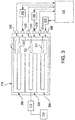
FIG. 3 is a schematic depiction of the actuator ofFIG. 2 , showing the connections between the signal connectors and electromechanical motor power connectors; -
FIG. 4 illustrates an exemplary state diagram that specifies the operation of a multi-redundant actuator control system, in accordance with an embodiment of the present invention; and -
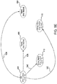
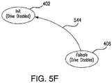
FIGS. 5A-5F illustrate a plurality of transitions for each state of the diagram ofFIG. 4 , in accordance with an embodiment of the present invention. - The present invention is now described more fully with reference to the accompanying drawings, in which illustrated embodiments of the present invention are shown wherein like reference numerals identify like elements. The present invention is not limited in any way to the illustrated embodiments as the illustrated embodiments described below are merely exemplary of the invention, which can be embodied in various forms, as appreciated by one skilled in the art. Therefore, it is to be understood that any structural and functional details disclosed herein are not to be interpreted as limiting, but merely as a basis for the claims and as a representative for teaching one skilled in the art to variously employ the present invention. Furthermore, the terms and phrases used herein are not intended to be limiting but rather to provide an understandable description of the invention.
- Unless defined otherwise, all technical and scientific terms used herein have the same meaning as commonly understood by one of ordinary skill in the art to which this invention belongs. Although any methods and materials similar or equivalent to those described herein can also be used in the practice or testing of the present invention, exemplary methods and materials are now described. It must be noted that as used herein and in the appended claims, the singular forms "a", "an," and "the" include plural referents unless the context clearly dictates otherwise. Thus, for example, reference to "a stimulus" includes a plurality of such stimuli and reference to "the signal" includes reference to one or more signals and equivalents thereof known to those skilled in the art, and so forth.
- Implementation of the techniques, blocks, steps and means described below may be done in various ways. For example, these techniques, blocks, steps and means may be implemented in hardware, software, or a combination thereof. For a hardware implementation, the processing units may be implemented within one or more application specific integrated circuits (ASICs), digital signal processors (DSPs), digital signal processing devices (DSPDs), programmable logic devices (PLDs), field-programmable gate arrays (FPGAs), soft core processors, hard core processors, controllers, micro-controllers, microprocessors, other electronic units designed to perform the functions described above, and/or a combination thereof. Software can be used instead of or in addition to hardware to perform the techniques, blocks, steps and means.
- As used herein, the term "software" is meant to be synonymous with any code or program that can be in a processor of a host computer, regardless of whether the implementation is in hardware, firmware or as a software computer product available on a disc, a memory storage device, or for download from a remote machine. The embodiments described herein include such software to implement the equations, relationships and algorithms described below. One skilled in the art will appreciate further features and advantages of the invention based on the below-described embodiments. Accordingly, the invention is not to be limited by what has been particularly shown and described, except as indicated by the appended claims.
- In exemplary embodiments, a computer system component may constitute a "module" that is configured and operates to perform certain operations as described herein below. Accordingly, the term "module" should be understood to encompass a tangible entity, be that an entity that is physically constructed, permanently configured (e.g., hardwired) or temporarily configured (e.g. programmed) to operate in a certain manner and to perform certain operations described herein.
- Embodiments of the present invention are directed to a multi-redundant actuator. Behaviors that characterize the operational mode of the vehicle are associated with the actuators. A complete fly-by-wire flight control system typically controls multiple independent surfaces (for example, left and right ailerons). The system includes independent actuators for each surface. Multiple electromechanical motors may drive a single actuator (redundant drive mechanism). More specifically, the electromechanical motors, operating in conjunction with one another, drive the specific flight surface they are tasked with driving. In various embodiments multiple electromechanical motors that are driving one flight control surface interact with each other and autonomously configure themselves based on current operating conditions. Each of the actuators contains control logic that monitors inputs and fault status and properly configures all the redundant electromechanical motors to the optimal control state (mode of operation). The redundant control electromechanical motors communicate with each other to determine which one is in control (master mode) and which ones slave to the master (slave mode). Advantageously, embodiments of the present invention provide the redundant actuator capable of self-configuring autonomously from a command source. The command source is typically a flight control computer operable in a flight state and a ground state. According to embodiments of the present invention, the redundant actuator system is configured to control performance of the redundant suite of electromechanical motors prior to commands being available from the command source.
- Reference will now be made to the drawings wherein like reference numerals identify similar structural features or aspects of the subject disclosure. For purposes of explanation and illustration, and not limitation, a partial view of an exemplary embodiment of an aircraft, here, an exemplary embodiment of an aircraft as a vertical takeoff and landing (VTOL) aircraft in accordance with the disclosure is shown in
FIG. 1 and is designated generally byreference character 100. Other embodiments of aircraft in accordance with the disclosure, or aspects thereof, are provided inFIGS. 2-3 , as will be described. The systems and methods described herein provide for increased reliability multi-redundant actuators that can be used in fly-by-wire systems, while providing an ability to operate autonomously as compared with traditional actuator systems. - As shown in
FIG. 1 ,VTOL aircraft 100 includes amain rotor system 102 andtail rotor system 104 supported by anairframe 106.Airframe 106 includes agearbox 108 interconnecting anengine 110 withmain rotor system 102 andtail rotor system 104.Main rotor system 102 is operatively connected to aswash plate 112.Swash plate 112 is operatively connected tohydraulic systems 114.VTOL aircraft 100 includeslinear actuators 116, e.g. electromechanical actuators, operatively connected to thehydraulic systems 114, for example, a mechanical hydraulic servoactuator. Although a particular VTOL aircraft configuration is illustrated and described in the disclosed embodiment, other configurations and/or machines, such as fixed wing aircraft, high speed compound rotary wing aircraft with supplemental translational thrust systems, dual contra-rotating, coaxial rotor system aircraft, turbo-props, tilt-rotors and tilt-wing aircraft, will also benefit from the present invention. - Although the fly-by-
wire system 118 illustrated inFIG. 1 includes threeactuators 116, other numbers of actuators may be used in other exemplary embodiments.System 118 includes aflight control computer 120 operatively connected to each ofelectromechanical motors 306. Eachactuator 116 ofsystem 118 is operatively connected to a respective one ofhydraulic systems 114.System 118 includes aflight control surface 122 of a rotorcraft,e.g. VTOL aircraft 100, operatively connected to at least one of threehydraulic systems 114 throughswash plate 112. - With reference now to
FIGS. 2 and3 ,actuator 116 includes ahousing 202.Housing 202 includes aconnector side 204 and aforcer rod side 206.Housing connector side 204 includes electromechanicalmotor power connectors 208 andsignal connectors 210. Electromechanicalmotor power connectors 208 are operatively connected between anelectromechanical motor drive 308, schematically shown inFIG. 3 , and respectiveelectromechanical motors 306, described below, to operatively connectelectromechanical motors 306 tomotor drive 308.Actuator 116 includes a plurality of linear variable differential transformers (LVDT) 302, e.g. a position sensor, to measure the absolute displacement ofelectromechanical motors 306.Signal connectors 210 operatively connectrespective LVDTs 302 toflight control computer 120.Signal connectors 210 receive actuator position signals from eachLVDT 302 and send them toflight control computer 120, which compares the true position ofactuator 116 to the commanded position from the pilot. - As schematically shown in
FIG. 3 ,signal connectors 210 each correspond to arespective LVDT 302. EachLVDT 302 is in electrical communication withflight control computer 120 throughsignal connectors 210 to convey the position ofLVDTs 302 and carriage 304. The position of carriage 304 corresponds to a respective position of each one ofelectromechanical motors 306. As such, by monitoring the position of carriage 304 andLVDTs 302 throughsignal connectors 210, actuator controller andflight control computer 120 can appropriately adjust the power sent from electromechanical motor drives 308 toelectromechanical motors 306 throughmotor power connectors 208 in order to achieve a desired position of carriage 304 along the longitudinal axis ofactuator 116. The desired position of carriage 304 will depend on the input from the pilot or other control system. Those skilled in the art will readily appreciate thatactuator 116 segregates threemotor power connectors 208 and the threesignal connectors 210, providing true redundancy between the systems, reducing the probability of failure due to a connector shorting out, or getting wet and losing connectivity. -
FIGS. 4 ,5A-5F illustrate various states and transitions supported by the disclosed multi-redundant actuator system. As shown inFIG. 4 , the electromechanical motor may assume one of the following states/modes:Init 402,Hold 404,Standby 406,Failsafe 408,Normal Master 410 andNormal Slave 412. For one preferred embodiment, the establishment of "master" versus "slave" status is automatically optimized for each electromechanical motor to best meet the current operating conditions as can be best sensed and/or predicted by the motor units. - In one embodiment, the
Init mode 402 may run an initialization routine (initialization code) which enables theelectromechanical motor 306 to communicate with the remaining electromechanical motors and with theFCC 120. Initialization code may be generated by a high-level language compiler into the embedded system programming. Electromechanical motor's drive is disabled in theInit mode 402. -
Standby mode 406 is opposite of active modes (such asNormal modes FCC 120, a second electromechanical motor may be placed inStandby mode 406 by theFCC 120 to provide as little resistance to flight surface's movement as possible. Electromechanical motor's drive is disabled in theStandby mode 406. - An inoperable
Failsafe mode 408 is also provided which is entered in the event a critical condition is detected by the system. Electromechanical motor's drive is disabled in theFailsafe mode 408 as well. - According to embodiments of the present invention, three active modes are provided:
Normal Slave mode 412,Normal Master mode 410 andHold mode 404. TheMaster mode 410 is an operation mode for an electromechanical motor to maintain control of the multi-redundant actuator system. The electromechanical motor operating in theMaster mode 410 can further control and manage other electromechanical motors operating inSlave mode 412. TheSlave mode 412 is an operation mode for an electromechanical motor to allow the other electromechanical motor, operating inMaster mode 410, to control and manage the system. If the electromechanical motor operating inMaster mode 410 stops receiving commands from theFCC 120, it automatically transfers into theHold mode 404 and holds its current position until a command is received from theFCC 120 or until another mode exit criteria are met, as discussed below. - According to embodiments of the present invention, the disclosed multi-redundant actuator system includes control logic configured to implement a set of rules. In an embodiment, according to the rule set, the system should have at least one electromechanical motor driving a control surface except for the following situations: a)
FCC 120 sends disable signals to all electromechanical motors; b) all electromechanical motors are commanded byFCC 120 to transition toStandby mode 406 for more than persistence. It should be noted that if a particular electromechanical motor automatically transitions toNormal state FCC 120 does not reciprocate with a normal mode command within a predefined number of communication cycles, then the electromechanical motor is configured to automatically transfer back toStandby mode 406. - According to another preconfigured rule of the disclosed multi-redundant actuator system, in a highly unlikely case of all electromechanical motors entering Normal state 410,412 at exactly the same time instance, the first electromechanical motor gets a priority for the "master" status. Once a particular
electromechanical motor 306 gets a "master" designation, thatelectromechanical motor 306 stays inMaster mode 410 until mode exit criteria (discussed below) are met. Advantageously, eachautonomous motor 306 is configured to ignore FCC mode command and configured to automatically transition intoNormal state FCC 120 to reciprocate withNormal mode Normal mode FCC 120 commands this particular electromechanical motor to go toStandby mode 406. Advantageously, this functionality allows theFCC 120 to recognize the failure and react to the failure, for example, by commanding the proper mode to the remaining electromechanical motors. At least in some cases theFCC 120 may override the automatic mode selection for a particular electromechanical motor if needed. - According to embodiments of the present invention, if a critical fault associated with one of the electromechanical motors is detected or if the
FCC 120 sends one of the electromechanical motors intoFailsafe mode 408, that electromechanical motor gets a chance to automatically reset itself up to N number of times, where N is a pre-defined number. If theelectromechanical motor 306 stops receiving commands from theFCC 120 and no other electromechanical motor is available, theelectromechanical motor 306 is configured to automatically transfer into theHold mode 404 and hold its current position. If theelectromechanical motor 306 stops receiving commands from theFCC 120 and one or more other electromechanical motors are available, theelectromechanical motor 306 is configured to automatically transfer into theStandby mode 406. According to embodiments of the present invention, the disclosed multi-redundant actuator system is configured to prioritizeNormal modes electromechanical motor 306 is configured to transition fromHold mode 404 toNormal mode FCC 120. In addition, theelectromechanical motor 306 is configured to transition fromHold mode 404 toStandby mode 406 if at least one of the plurality ofelectromechanical motors 306 is operating in one of theNormal modes -
FIGS. 5A-5F illustrate in detail various transitions supported by the disclosed multi-redundant actuator system.FIG. 5A illustrates available transitions for an electromechanical motor operating in theInit mode 402. According to an embodiment of the present invention, theelectromechanical motor 306transitions 502 from theInit mode 402 to theHold mode 404, in response to receiving no commands from theFCC 120 for a predefined number of communication cycles and in response to determining that all of the other electromechanical motors are operating in a mode different from theMaster mode 410 and theHold mode 404. In other words, the system is configured to ensure that there is only one electromechanical motor having a "master" designation. Theelectromechanical motor 306transitions 504 from theInit mode 402 to theMaster mode 410, in response to either receiving a master command indicating a master designation from theFCC 120 or in response to determining that no other electromechanical motor is operating in theMaster mode 410.Transition 504 is configured to ensure that there is always at least one electromechanical motor operating in theMaster mode 410. - According to an embodiment of the present invention, the
electromechanical motor 306transitions 506 from theInit mode 402 to theStandby mode 406, if the electromechanical motor's initialization routine has been successfully completed and the minimum initialization time is exceeded, or in response to receiving an invalid master command from theFCC 120 or in response to electromechanical motor's drive being disabled. In one embodiment, the invalid master command may occur if theFCC 120 commands one of the electromechanical motors to operate in theMaster mode 410, but that electromechanical motor actually experiences some kind of communication protocol issues. As noted above, one of the electromechanical motors may be intentionally left in theStandby mode 406 if another electromechanical motor powers the flight surface. In this scenario, the electromechanical motor operating in theStandby mode 406 provides as little resistance to flight surface's movement as possible. - With continued reference to
FIG. 5A , if theelectromechanical motor 306 determines that at least one other electromechanical motor is operating in eitherMaster mode 410 orHold mode 404 then transition 508 is made to theSlave mode 412. Alternatively, theSlave mode 412 may be entered 508 from theInit mode 402, in response to detecting the master command being sent from theFCC 120 to another one of the plurality of electromechanical motors within the system. Thetransition 510 between theInit mode 402 and theFailsafe mode 408 may be made in response to detecting a critical fault. In one embodiment, a critical fault may include an electronic defect or failure. -
FIG. 5B illustrates available transitions for an electromechanical motor operating in theStandby mode 406. According to an embodiment of the present invention, theelectromechanical motor 306transitions 512 from theStandby mode 406 to theHold mode 404, if theelectromechanical motor 306 determines that its drive is enabled and in response to receiving no commands from theFCC 120 for a predefined number of communication cycles and in response to determining that all of the other electromechanical motors are operating in a mode different from theMaster mode 410 and theHold mode 404. Another exit criterion for thetransition 512 may include the determination that all cross lane data links (between the plurality of electromechanical motors) are valid. Theelectromechanical motor 306transitions 514 from theStandby mode 406 to theMaster mode 410, if electromechanical motor's 306drive 308 is enabled and in response to either receiving a command indicating a master designation from theFCC 120 or in response to determining that no other electromechanical motor is operating in theMaster mode 410. - Still referring to
FIG. 5B , if theelectromechanical motor 306 determines that its drive is enabled and at least one other electromechanical motor is operating in eitherMaster mode 410 orHold mode 404, then transition 516 is made to theSlave mode 412. Alternatively, theSlave mode 412 may be entered 516 from theStandby mode 406, in response to detecting the master command being sent from theFCC 120 to another one of the plurality of electromechanical motors within the system. Thetransition 518 between theStandby mode 406 and theFailsafe mode 408 may be made in response to detecting a critical fault. -
FIG. 5C illustrates available transitions for an electromechanical motor operating in theSlave mode 412. According to an embodiment of the present invention, theelectromechanical motor 306transitions 520 from theSlave mode 412 to theHold mode 404, in response to receiving no commands from theFCC 120 for a predefined number of communication cycles and in response to lost communication with all other redundant electromechanical motors or in response to determining that all of the other electromechanical motors are operating in a mode different from theHold mode 404 and the other electromechanical motors report loss of communication with theFCC 120 or if the other electromechanical motors are operating in a mode different from theSlave mode 412 and different from theMaster mode 410. Theelectromechanical motor 306transitions 522 from theSlave mode 412 to theMaster mode 410, in response to either receiving a master designation from other electromechanical motors and Big Brother Logic (BBL) being active or in response to BBL not being active and receiving a command indicating a master designation over a valid communication link with theFCC 120. In various embodiments, the BBL is designed to resolve conflicts between redundant electromechanical motors and to determine corrective action. Another exit criterion for thetransition 522 may include a receipt of a command indicating a designation different from the master designation and the determination that no other electromechanical motor is operating in theMaster mode 410. - With further reference to
FIG. 5C , if theelectromechanical motor 306 determines that its drive is disabled or if an invalid master command is received from theFCC 120, then transition 524 is made to theStandby mode 406. Thetransition 526 between theSlave mode 412 and theFailsafe mode 408 may be made in response to detecting a critical fault. -
FIG. 5D illustrates available transitions for an electromechanical motor operating in theMaster mode 410. According to an embodiment of the present invention, theelectromechanical motor 306transitions 528 from theMaster mode 410 to theHold mode 404, in response to receiving no commands from theFCC 120 for a predefined number of communication cycles and in response to determining that all of the other electromechanical motors are operating in a mode different from theMaster mode 410. Theelectromechanical motor 306transitions 530 from theMaster mode 410 to theStandby mode 406, if theelectromechanical motor 306 determines that thedrive 308 is disabled or if theelectromechanical motor 306 determines that the invalid master command was received from theFCC 120. - Still referring to
FIG. 5D , if theelectromechanical motor 306 determines that BBL is being active and in response to at least one of the other ones of the plurality of electromechanical motors sending a master command indicating a master designation to a different one of the other ones of the plurality of electromechanical motors, theelectromechanical motor 306transitions 534 from theMaster mode 410 to theSlave mode 412. It should be noted that if two or moreelectromechanical motors 306 operate in theMaster mode 410 simultaneously, theFCC 120 may be configured to pick the designated master electromechanical motor by sending a new identification number to the picked electromechanical motor. Advantageously, in such scenario the configured control logic enables other electromechanical motors to switch to other modes of operation automatically. Other exit criteria for thetransition 534 may include 1) BBL being inactive and a receipt of a command indicating master designation sent from theFCC 120 to a different electromechanical motor; or 2) detecting that at least one of the other ones of the plurality of electromechanical motors having a lower identification number is operating in theMaster mode 410. Thetransition 532 between theNormal mode 410 and theFailsafe mode 408 may be made in response to detecting a critical fault. -
FIG. 5E illustrates available transitions for an electromechanical motor operating in theHold mode 404. According to an embodiment of the present invention, theelectromechanical motor 306transitions 538 from theHold mode 404 to theStandby mode 406, if theelectromechanical motor 306 determines that thedrive 308 is disabled or if theelectromechanical motor 306 determines that the invalid master command was received from theFCC 120. Theelectromechanical motor 306transitions 540 from theHold mode 404 to theMaster mode 410, in response to having an operable link with theFCC 120 and either in response to receiving a command from theFCC 120 indicating the current master designation is valid or in response to receiving a master designation command from theFCC 120. - Still referring to
FIG. 5E , if theelectromechanical motor 306 receives a command from theFCC 120 confirming a valid master designation and all cross lane data links (between the plurality of electromechanical motors) are valid and at least one other electromechanical motor operates in theMaster mode 410 and in response to determining that all of the other ones of the plurality of electromechanical motors are connected to each other and are connected to theFCC 120, theelectromechanical motor 306transitions 542 from theHold mode 404 to theSlave mode 412. Thetransition 536 between theHold mode 404 and theFailsafe mode 408 may be made in response to detecting a critical fault. -
FIG. 5F illustrates available transition for an electromechanical motor operating in theFailsafe mode 408. As noted above, according to embodiments of the present invention, if a critical fault associated with one of the electromechanical motors is detected, that electromechanical motor gets a chance to automatically reset itself up to N number of times, where N is a pre-defined number. Thetransition 544 between theFailsafe mode 404 and theInit mode 402 may be made only if the number of retries is lower than a threshold number N. - In summary, various embodiments of the present invention are directed to a multi-redundant actuator control system. The redundant electromechanical motors communicate with each other to determine which one is in control (master mode) and which electromechanical motors slave to the master (slave mode). Advantageously, embodiments of the present invention provide the redundant actuator capable of self-configuring autonomously from a command source. The command source is typically a flight control computer operable in a flight state and a ground state. According to embodiments of the present invention, the redundant actuator is configured to control performance of the redundant suite of electromechanical motors prior to commands being available from the command source.
- As will be appreciated by one skilled in the art, aspects of the present invention may be embodied as a system, method or computer program product. Accordingly, aspects of the present invention may take the form of an entirely hardware embodiment, an entirely software embodiment (including firmware, resident software, micro-code, etc.) or an embodiment combining software and hardware aspects that may all generally be referred to herein as a "circuit," "module" or "system." Furthermore, aspects of the present invention may take the form of a computer program product embodied in one or more computer readable medium(s) having computer readable program code embodied thereon.
- Any combination of one or more computer readable medium(s) may be utilized. The computer readable medium may be a computer readable signal medium or a computer readable storage medium. A computer readable storage medium may be, for example, but not limited to, an electronic, magnetic, optical, electromagnetic, infrared, or semiconductor system, apparatus, or device, or any suitable combination of the foregoing. More specific examples (a non-exhaustive list) of the computer readable storage medium would include the following: an electrical connection having one or more wires, a portable computer diskette, a hard disk, a random access memory (RAM), a read-only memory (ROM), an erasable programmable read-only memory (EPROM or Flash memory), an optical fiber, a portable compact disc read-only memory (CD-ROM), an optical storage device, a magnetic storage device, or any suitable combination of the foregoing. In the context of this document, a computer readable storage medium may be any tangible medium that can contain, or store a program for use by or in connection with an instruction execution system, apparatus, or device.
- A computer readable signal medium may include a propagated data signal with computer readable program code embodied therein, for example, in baseband or as part of a carrier wave. Such a propagated signal may take any of a variety of forms, including, but not limited to, electro-magnetic, optical, or any suitable combination thereof. A computer readable signal medium may be any computer readable medium that is not a computer readable storage medium and that can communicate, propagate, or transport a program for use by or in connection with an instruction execution system, apparatus, or device.
- Program code embodied on a computer readable medium may be transmitted using any appropriate medium, including but not limited to wireless, wireline, optical fiber cable, RF, etc., or any suitable combination of the foregoing.
- Computer program code for carrying out operations for aspects of the present invention may be written in any combination of one or more programming languages, including an object oriented programming language such as Java, Smalltalk, C++ or the like and conventional procedural programming languages, such as the "C" programming language or similar programming languages that can be converted to a machine language. The program code may also be written in a Hardware Descriptor Language (HDL). HDLs are frequently used to specify circuit designs for an integrated circuit (IC), such as a field programmable gate array (FPGA), application specific integrated circuit (ASIC), or the like. An electronic design automation (EDA) tool compiles HDL code specifying a circuit design for implementation in a target IC. Example HDLs include Verilog, SystemVerilog, and VHDL.
- The flowchart and block diagrams in the Figures illustrate the architecture, functionality, and operation of possible implementations of systems, methods and computer program products according to various embodiments of the present invention. In this regard, each block in the flowchart or block diagrams may represent a module, segment, or portion of code, which comprises one or more executable instructions for implementing the specified logical function(s). It should also be noted that, in some alternative implementations, the functions noted in the block may occur out of the order noted in the figures. For example, two blocks shown in succession may, in fact, be executed substantially concurrently, or the blocks may sometimes be executed in the reverse order, depending upon the functionality involved. It will also be noted that each block of the block diagrams and/or flowchart illustration, and combinations of blocks in the block diagrams and/or flowchart illustration, can be implemented by special purpose hardware-based systems that perform the specified functions or acts, or combinations of special purpose hardware and computer instructions.
- The descriptions of the various embodiments of the present invention have been presented for purposes of illustration, but are not intended to be exhaustive or limited to the embodiments disclosed. Many modifications and variations will be apparent to those of ordinary skill in the art without departing from the scope and spirit of the described embodiments. The terminology used herein was chosen to best explain the principles of the embodiments, the practical application or technical improvement over technologies found in the marketplace, or to enable others of ordinary skill in the art to understand the embodiments disclosed herein.
Claims (15)
- A fly-by-wire system (118) comprising:an electromechanical actuator (116) comprising a plurality of electromechanical motors (306), each one the plurality of electromechanical motors is configured and operable to:exchange operating status information with other ones of the plurality of electromechanical motors; andautomatically configure itself for optimal mode of operation based on the received operating status information of at least one of the other ones of the plurality of electromechanical motors; anda flight control computer (120) operatively connected to each one of the plurality of electromechanical motors (306) of the electromechanical actuator (116).
- The system of claim 1, wherein the optimal mode comprises one of the following: Init, Hold, Standby, Failsafe, Master and Slave.
- The system of claim 2, wherein one of the plurality of electromechanical motors (306) is operating in the Init mode and wherein the one of the plurality of electromechanical motors (306) is configured to transfer to the optimal mode comprising:Hold mode, in response to receiving no commands from the flight control computer (120) for a predefined number of communication cycles and in response to determining that the other ones of the plurality of electromechanical motors (306) are operating in a mode different from the Master mode and different from the Hold mode;Master mode, in response to receiving a master command indicating master designation from the flight control computer (120) or in response to determining that all of the other ones of the plurality of electromechanical motors (306) are operating in a mode different from the Master mode;Standby mode, in response to determining that electromechanical motor's initialization routine is complete and in response to receiving an invalid master command from the flight control computer or in response to electromechanical motor's drive being disabled;Slave mode, in response to determining that at least one of the other ones of the plurality of electromechanical motors (306) is operating in the Master mode or is operating in the Hold mode or in response to detecting a master command indicating master designation sent from the flight control computer (120) to one of the other ones of the plurality of electromechanical motors (306);Failsafe mode, in response to detecting a critical fault.
- The system of claim 2, wherein one of the plurality of electromechanical motors (306) is operating in the Standby mode and wherein the one of the plurality of electromechanical motors (306) is configured to transfer to the optimal mode comprising:Hold mode, in response to electromechanical motor's drive being enabled and in response to receiving no commands from the flight control computer (120) for a predefined number of communication cycles and in response to determining that all of the other ones of the plurality of electromechanical motors (306) are operating in a mode different from the Master mode and different from the Hold mode;Master mode, in response to electromechanical motor's drive being enabled and in response to receiving a master command indicating master designation from the flight control computer or in response to determining that all of the other ones of the plurality of electromechanical motors (306) are operating in a mode different from the Master mode;Slave mode, in response to electromechanical motor's drive being enabled and in response to determining that at least one of the other ones of the plurality of electromechanical motors (306) is operating in the Master mode or is operating in the Hold mode or in response to detecting a master command indicating master designation sent from the flight control computer (120) to one of the other ones of the plurality of electromechanical motors (306);Failsafe mode, in response to detecting a critical fault.
- The system of claim 2, wherein one of the plurality of electromechanical motors (306) is operating in the Slave mode and wherein the one of the plurality of electromechanical motors (306) is configured to transfer to the optimal mode comprising:Hold mode, in response to receiving no commands from the flight control computer (120) for a predefined number of communication cycles and in response to lost communication with all of the other ones of the plurality of electromechanical motors (306) or in response to determining that all of the other ones of the plurality of electromechanical motors (306) are operating in a mode different from the Hold mode and all of the other ones of the plurality of electromechanical motors (306) lost communication with the flight control computer (120);Master mode, in response to receiving a master command indicating master designation from at least one of the other ones of the plurality of electromechanical motors (306) and in response to Big Brother Logic (BBL) being active or in response to the BBL being inactive and in response to receiving a master command indicating a master designation from the flight control computer;Standby mode, in response to electromechanical motor's drive being disabled or in response to receiving invalid master command from the flight control computer;Failsafe mode, in response to detecting a critical fault.
- The system of claim 2, wherein one of the plurality of electromechanical motors (306) is operating in the Master mode and wherein the one of the plurality of electromechanical motors (306) is configured to transfer to the optimal mode comprising:Hold mode, in response to receiving no commands from the flight control computer (120) for a predefined number of communication cycles and in response to determining that all of the other ones of the plurality of actuators (116) are operating in a mode different from the Master mode;Standby mode, in response to electromechanical motor's drive being disabled or in response to receiving invalid master command from the flight control computer (120);Slave mode, in response to BBL being active and in response to at least one of the other ones of the plurality of electromechanical motors (306) sending a master command indicating a master designation to a different one of the other ones of the plurality of electromechanical motors or in response to the BBL being inactive and in response to detecting the command indicating master designation sent from the flight control computer (120) to one of the other ones of the plurality of electromechanical motors (306) or in response to detecting that at least one of the other ones of the plurality of electromechanical motors (306) having a lower identification number is operating in a Master mode;Failsafe mode, in response to detecting a critical fault.
- The system of claim 2, wherein one of the plurality of electromechanical motors (306) is operating in the Hold mode and wherein the one of the plurality of electromechanical motors (306) is configured to transfer to the optimal mode comprising:Standby mode, in response to electromechanical motor's drive being disabled or in response to receiving invalid master command from the flight control computer (120);Master mode, in response to receiving a command indicating that a current master designation is valid from the flight control computer (120) or in response to receiving a master command indicating a master designation from the flight control computer (120);Slave mode, in response to receiving a command indicating that a current master designation is valid from the flight control computer (120) or in response to receiving a master command indicating a master designation from the flight control computer and in response to determining that at least one of the other ones of the plurality of electromechanical motors (306) is operating in the Master mode and in response to determining that all of the other ones of the plurality of electromechanical motors (306) are connected to each other and are connected to the flight control computer (120);Failsafe mode, in response to detecting a critical fault.
- The system of claim 2, wherein one of the plurality of electromechanical motors (306) is operating in the Failsafe mode and wherein the one of the plurality of electromechanical motors (306) is configured to transfer to the Init mode in response to determining that a number of preceding attempts to transfer to the Init mode is lower than a predefined reset threshold.
- The system of claim 2, wherein one of the plurality of electromechanical motors (306) operating in the Init mode is configured to run electromechanical motor's initialization routine.
- A method for autonomously reconfiguring a multi-redundant actuator control system, the method comprising steps of:exchanging operating status information between a plurality of electromechanical motors within an electromechanical actuator and a flight control computer, wherein the flight control computer is operatively connected to the plurality of electromechanical motors; andautomatically configuring each of the plurality of electromechanical motors for optimal mode of operation based on the exchanged operating status information.
- The method of claim 10, wherein the optimal mode comprises one of the following: Init, Hold, Standby, Failsafe, Master and Slave.
- The method of claim 11, wherein one of the plurality of electromechanical motors is operating in the Init mode and wherein the method further comprises the step of transferring to the optimal mode comprising:Hold mode, in response to receiving no commands from the flight control computer for a predefined number of communication cycles and in response to determining that the other ones of the plurality of electromechanical motors are operating in a mode different from the Master mode and different from the Hold mode;Master mode, in response to receiving a master command indicating master designation from the flight control computer or in response to determining that all of the other ones of the plurality of electromechanical motors are operating in a mode different from the Master mode;Standby mode, in response to determining that electromechanical motor's initialization routine is complete and in response to receiving an invalid master command from the flight control computer or in response to electromechanical motor's drive being disabled;Slave mode, in response to determining that at least one of the other ones of the plurality of electromechanical motors is operating in the Master mode or is operating in the Hold mode or in response to detecting a master command indicating master designation sent from the flight control computer to one of the other ones of the plurality of electromechanical motors;Failsafe mode, in response to detecting a critical fault.
- The method of claim 11, wherein one of the plurality of electromechanical motors is operating in the Standby mode and wherein the method further comprises the step of transferring to the optimal mode comprising:Hold mode, in response to electromechanical motor's drive being enabled and in response to receiving no commands from the flight control computer for a predefined number of communication cycles and in response to determining that all of the other ones of the plurality of electromechanical motors are operating in a mode different from the Master mode and different from the Hold mode;Master mode, in response to electromechanical motor's drive being enabled and in response to receiving a master command indicating master designation from the flight control computer or in response to determining that all of the other ones of the plurality of electromechanical motors are operating in a mode different from the Master mode ;Slave mode, in response to electromechanical motor's drive being enabled and in response to determining that at least one of the other ones of the plurality of electromechanical motors is operating in the Master mode or is operating in the Hold mode or in response to detecting a master command indicating master designation sent from the flight control computer to one of the other ones of the plurality of electromechanical motors;Failsafe mode, in response to detecting a critical fault.
- The method of claim 11, wherein one of the plurality of electromechanical motors is operating in the Slave mode and wherein the method further comprises the step of transferring to the optimal mode comprising:Hold mode, in response to receiving no commands from the flight control computer for a predefined number of communication cycles and in response to lost communication with all of the other ones of the plurality of electromechanical motors or in response to determining that all of the other ones of the plurality of electromechanical motors are operating in a mode different from the Hold mode and all of the other ones of the plurality of electromechanical motors lost communication with the flight control computer;Master mode, in response to receiving a master command indicating master designation from at least one of the other ones of the plurality of electromechanical motors and in response to Big Brother Logic (BBL) being active or in response to the BBL being inactive and in response to receiving a master command indicating a master designation from the flight control computer;Standby mode, in response to electromechanical motor's drive being disabled or in response to receiving invalid master command from the flight control computer;Failsafe mode, in response to detecting a critical fault.
- The method of claim 11, wherein one of the plurality of electromechanical motors is operating in the Master mode and wherein the method further comprises the step of transferring to the optimal mode comprising:Hold mode, in response to receiving no commands from the flight control computer for a predefined number of communication cycles and in response to determining that all of the other ones of the plurality of actuators are operating in a mode different from the Master mode;Standby mode, in response to electromechanical motor's drive being disabled or in response to receiving invalid master command from the flight control computer;Slave mode, in response to BBL being active and in response to at least one of the other ones of the plurality of electromechanical motors sending a master command indicating a master designation to a different one of the other ones of the plurality of electromechanical motors or in response to the BBL being inactive and in response to detecting the command indicating master designation sent from the flight control computer to one of the other ones of the plurality of electromechanical motors or in response to detecting that at least one of the other ones of the plurality of electromechanical motors having a lower identification number is operating in a Master mode;Failsafe mode, in response to detecting a critical fault; orwherein one of the plurality of electromechanical motors is operating in the Hold mode and wherein the method further comprises the step of transferring to the optimal mode comprising:Standby mode, in response to electromechanical motor's drive being disabled or in response to receiving invalid master command from the flight control computer;Master mode, in response to receiving a command indicating that a current master designation is valid from the flight control computer or in response to receiving a master command indicating a master designation from the flight control computer;Slave mode, in response to receiving a command indicating that a current master designation is valid from the flight control computer or in response to receiving a master command indicating a master designation from the flight control computer and in response to determining that at least one of the other ones of the plurality of electromechanical motors is operating in the Master mode and in response to determining that all of the other ones of the plurality of electromechanical motors are connected to each other and are connected to the flight control computer;Failsafe mode, in response to detecting a critical fault; orwherein one of the plurality of electromechanical motors is operating in the Failsafe mode and wherein the method further comprises the step of transferring to the Init mode in response to determining that a number of preceding attempts to transfer to the Init mode is lower than a predefined reset threshold; orwherein one of the plurality of electromechanical motors operating in the Init mode is configured to run actuator's initialization routine.
Applications Claiming Priority (1)
| Application Number | Priority Date | Filing Date | Title |
|---|---|---|---|
| US15/886,609 US10843792B2 (en) | 2018-02-01 | 2018-02-01 | Autonomous reconfiguration of a multi-redundant actuator control system |
Publications (2)
| Publication Number | Publication Date |
|---|---|
| EP3522368A1 true EP3522368A1 (en) | 2019-08-07 |
| EP3522368B1 EP3522368B1 (en) | 2022-07-13 |
Family
ID=65276003
Family Applications (1)
| Application Number | Title | Priority Date | Filing Date |
|---|---|---|---|
| EP19154772.8A Active EP3522368B1 (en) | 2018-02-01 | 2019-01-31 | Autonomous reconfiguration of a multi-redundant actuator control system |
Country Status (2)
| Country | Link |
|---|---|
| US (1) | US10843792B2 (en) |
| EP (1) | EP3522368B1 (en) |
Families Citing this family (8)
| Publication number | Priority date | Publication date | Assignee | Title |
|---|---|---|---|---|
| US10810114B2 (en) * | 2018-04-02 | 2020-10-20 | Hamilton Sundstrand Corporation | Testing autonomous reconfiguration logic for an electromechanical actuator |
| US11749122B1 (en) * | 2019-12-12 | 2023-09-05 | Amazon Technologies, Inc. | Multi-device redundant flight controller |
| US12321176B2 (en) * | 2020-08-14 | 2025-06-03 | Waymo Llc | Steering system fault response for autonomous vehicles |
| EP4122818B1 (en) | 2021-07-19 | 2025-01-08 | Goodrich Actuation Systems SAS | System for controlling a flight control surface |
| EP4209415B1 (en) | 2022-01-06 | 2024-09-18 | Goodrich Actuation Systems SAS | Electromechanical actuator |
| CN116125870B (en) * | 2022-12-22 | 2025-08-01 | 四川沃飞长空科技发展有限公司 | Redundancy control method, arbitration unit, flight control system and storage medium |
| JP2024107889A (en) * | 2023-01-30 | 2024-08-09 | 双葉電子工業株式会社 | Receiving device |
| US12500533B2 (en) | 2024-01-02 | 2025-12-16 | Honeywell International Inc. | Dual-channel, position sensor for electromechanical actuator controller with backup control lane |
Citations (2)
| Publication number | Priority date | Publication date | Assignee | Title |
|---|---|---|---|---|
| US20070007385A1 (en) * | 2005-06-27 | 2007-01-11 | Honeywell International, Inc. | Electric flight control surface actuation system electronic architecture |
| US20100084517A1 (en) * | 2008-10-08 | 2010-04-08 | Honeywell International Inc. | Electromechanical actuation system and method |
Family Cites Families (28)
| Publication number | Priority date | Publication date | Assignee | Title |
|---|---|---|---|---|
| US4472780A (en) * | 1981-09-28 | 1984-09-18 | The Boeing Company | Fly-by-wire lateral control system |
| US5670856A (en) * | 1994-11-07 | 1997-09-23 | Alliedsignal Inc. | Fault tolerant controller arrangement for electric motor driven apparatus |
| US5806805A (en) * | 1996-08-07 | 1998-09-15 | The Boeing Company | Fault tolerant actuation system for flight control actuators |
| US7017861B1 (en) * | 2000-05-22 | 2006-03-28 | Saab Ab | Control system for actuators in an aircraft |
| US6776376B2 (en) * | 2002-10-18 | 2004-08-17 | Hamilton Sunstrand | Flight control surface actuation system |
| US7098619B2 (en) * | 2004-01-28 | 2006-08-29 | Stridsberg Innovation Ab | Actuator and movement linkage system |
| US7607611B2 (en) * | 2005-05-11 | 2009-10-27 | Honeywell International Inc. | Flight control surface actuation system with redundantly configured and lockable actuator assemblies |
| US20060255207A1 (en) * | 2005-05-11 | 2006-11-16 | Honeywell International, Inc. | Flight control surface actuation system with redundantly configured actuator assemblies |
| US7549605B2 (en) * | 2005-06-27 | 2009-06-23 | Honeywell International Inc. | Electric flight control surface actuation system for aircraft flaps and slats |
| BRPI0706613A2 (en) * | 2006-01-17 | 2011-04-05 | Gulfstream Aerospace Corp | apparatus and method for backup control in a distributed video control system |
| US8386093B2 (en) * | 2007-04-05 | 2013-02-26 | Bombardier Inc. | Multi-axis serially redundant, single channel, multi-path fly-by-wire flight control system |
| FR2927308B1 (en) | 2008-02-08 | 2010-10-22 | Airbus France | DISTRIBUTED FLIGHT CONTROL SYSTEM. |
| DE102008022092A1 (en) * | 2008-05-05 | 2009-11-19 | Airbus Deutschland Gmbh | Fault-tolerant control system for adjusting the flaps of an aircraft with adjustable kinematics with a fixed axis of rotation |
| EP2342609B1 (en) * | 2008-10-03 | 2015-03-04 | Bell Helicopter Textron Inc. | Method and apparatus for aircraft sensor and actuator failure protection using reconfigurable flight control laws |
| FR2941912B1 (en) * | 2009-02-10 | 2011-02-18 | Airbus France | FLIGHT CONTROL SYSTEM AND AIRCRAFT COMPRISING SAME |
| FR2941913B1 (en) * | 2009-02-10 | 2012-08-31 | Airbus France | FLIGHT CONTROL SYSTEM AND AIRCRAFT COMPRISING SAME |
| FR2943036B1 (en) | 2009-03-11 | 2011-04-15 | Airbus France | DISTRIBUTED FLIGHT CONTROL SYSTEM IMPLEMENTED ACCORDING TO AN INTEGRATED MODULAR AVIONIC ARCHITECTURE. |
| FR2959835B1 (en) | 2010-05-10 | 2012-06-15 | Airbus Operations Sas | FLIGHT CONTROL SYSTEM AND AIRCRAFT COMPRISING SAME |
| US8930036B2 (en) | 2011-04-13 | 2015-01-06 | GM Global Technology Operations LLC | Reconfigurable interface-based electrical architecture |
| FR2982239B1 (en) * | 2011-11-08 | 2014-05-09 | Airbus Operations Sas | METHOD AND DEVICE FOR DETECTING THE BLOCKING OF AN AIRCRAFT GOVERNMENT |
| JP6227239B2 (en) * | 2011-11-16 | 2017-11-08 | ナブテスコ株式会社 | Aircraft control apparatus and aircraft control system |
| US9156547B2 (en) * | 2012-02-09 | 2015-10-13 | Textron Innovations Inc. | System and method of actuating a swashplate for main rotor control |
| FR2996651B1 (en) * | 2012-10-05 | 2014-12-12 | Airbus Operations Sas | FLIGHT CONTROL SYSTEM USING SIMPLEX AND AIRCRAFT COMPUTERS COMPUTERS |
| JP6178571B2 (en) * | 2012-12-26 | 2017-08-09 | 三菱航空機株式会社 | Rotor actuator device, aircraft rotor blade, and aircraft |
| JP6178587B2 (en) * | 2013-02-28 | 2017-08-09 | 三菱航空機株式会社 | Aircraft actuator device and aircraft |
| WO2016016135A1 (en) | 2014-07-30 | 2016-02-04 | Siemens Aktiengesellschaft | Method and system for assigning a control authorization to a computer |
| US10326398B2 (en) * | 2016-10-06 | 2019-06-18 | Hamilton Sundstrand Corporation | Linear motor actuators |
| US10810114B2 (en) * | 2018-04-02 | 2020-10-20 | Hamilton Sundstrand Corporation | Testing autonomous reconfiguration logic for an electromechanical actuator |
-
2018
- 2018-02-01 US US15/886,609 patent/US10843792B2/en active Active
-
2019
- 2019-01-31 EP EP19154772.8A patent/EP3522368B1/en active Active
Patent Citations (2)
| Publication number | Priority date | Publication date | Assignee | Title |
|---|---|---|---|---|
| US20070007385A1 (en) * | 2005-06-27 | 2007-01-11 | Honeywell International, Inc. | Electric flight control surface actuation system electronic architecture |
| US20100084517A1 (en) * | 2008-10-08 | 2010-04-08 | Honeywell International Inc. | Electromechanical actuation system and method |
Also Published As
| Publication number | Publication date |
|---|---|
| EP3522368B1 (en) | 2022-07-13 |
| US10843792B2 (en) | 2020-11-24 |
| US20190233087A1 (en) | 2019-08-01 |
Similar Documents
| Publication | Publication Date | Title |
|---|---|---|
| EP3522368B1 (en) | Autonomous reconfiguration of a multi-redundant actuator control system | |
| EP3550391B1 (en) | Testing autonomous reconfiguration logic for an electomechanical actuator | |
| KR101477275B1 (en) | Primary flight controls | |
| US20150274293A1 (en) | System for a Vehicle with Redundant Computers | |
| US20170300065A1 (en) | Automatic recovery systems and methods for unmanned aircraft systems | |
| EP2619634B1 (en) | Remote data concentrator | |
| BRPI1102364A2 (en) | aircraft and aircraft flight control system | |
| CN105122152A (en) | Control of aircraft systems with at least two remote data concentrators for control of an aircraft system component | |
| EP3839688B1 (en) | Motor control system, method of operating a motor control system and aircraft | |
| CN110710164B (en) | Flight control system | |
| KR101951642B1 (en) | Apparatus for redundant drive structure for manned and unmanned aerial vehicles | |
| EP2905497A2 (en) | Selective electrical control of electromechanical clutch assmbly | |
| BR102023006635A2 (en) | FULLY REDUNDANT TRIPLEX ELECTRIC CABLE CONTROL ARCHITECTURE | |
| CN110667826B (en) | High-lift distributed telex control system | |
| CN115833701A (en) | Servo controller and its redundancy management method | |
| EP4582882A1 (en) | Dual-channel, high-integrity position sensor for electromechanical actuator controller with backup control lane | |
| CN113401333B (en) | High-lift system of airplane and slat operation instruction determination method for high-lift system | |
| RU2485568C2 (en) | Modular electronic flight control system | |
| KR101530181B1 (en) | Redundant driving control system having virtual control structure | |
| CN114114894A (en) | A fly-by-wire backup control system and method | |
| CN115556924B (en) | Flight control system and actuator control electronics and methods | |
| CN114384922A (en) | Unmanned aerial vehicle flight control redundancy technology | |
| EP3521671B1 (en) | Dual-concentric control valve with direct drive control and failed motor protection | |
| KR101494780B1 (en) | Electro-mechanical actuator of unmanned aerial vehicle and control method thereof | |
| JP2025020082A (en) | Systems and methods for detecting abnormal wingtip extension on folding wingtip aircraft |
Legal Events
| Date | Code | Title | Description |
|---|---|---|---|
| PUAI | Public reference made under article 153(3) epc to a published international application that has entered the european phase |
Free format text: ORIGINAL CODE: 0009012 |
|
| STAA | Information on the status of an ep patent application or granted ep patent |
Free format text: STATUS: THE APPLICATION HAS BEEN PUBLISHED |
|
| AK | Designated contracting states |
Kind code of ref document: A1 Designated state(s): AL AT BE BG CH CY CZ DE DK EE ES FI FR GB GR HR HU IE IS IT LI LT LU LV MC MK MT NL NO PL PT RO RS SE SI SK SM TR |
|
| AX | Request for extension of the european patent |
Extension state: BA ME |
|
| RIN1 | Information on inventor provided before grant (corrected) |
Inventor name: AVRITCH, STEVEN A. Inventor name: ELDRIGE, JEFFREY A. Inventor name: DICKIE, DAVID F. |
|
| STAA | Information on the status of an ep patent application or granted ep patent |
Free format text: STATUS: REQUEST FOR EXAMINATION WAS MADE |
|
| 17P | Request for examination filed |
Effective date: 20191216 |
|
| RBV | Designated contracting states (corrected) |
Designated state(s): AL AT BE BG CH CY CZ DE DK EE ES FI FR GB GR HR HU IE IS IT LI LT LU LV MC MK MT NL NO PL PT RO RS SE SI SK SM TR |
|
| STAA | Information on the status of an ep patent application or granted ep patent |
Free format text: STATUS: EXAMINATION IS IN PROGRESS |
|
| 17Q | First examination report despatched |
Effective date: 20210518 |
|
| GRAP | Despatch of communication of intention to grant a patent |
Free format text: ORIGINAL CODE: EPIDOSNIGR1 |
|
| STAA | Information on the status of an ep patent application or granted ep patent |
Free format text: STATUS: GRANT OF PATENT IS INTENDED |
|
| RIC1 | Information provided on ipc code assigned before grant |
Ipc: B64C 13/50 20060101ALN20211221BHEP Ipc: H02P 5/00 20160101ALI20211221BHEP Ipc: G05D 1/00 20060101ALI20211221BHEP Ipc: H02P 29/024 20160101AFI20211221BHEP |
|
| INTG | Intention to grant announced |
Effective date: 20220126 |
|
| GRAS | Grant fee paid |
Free format text: ORIGINAL CODE: EPIDOSNIGR3 |
|
| GRAA | (expected) grant |
Free format text: ORIGINAL CODE: 0009210 |
|
| STAA | Information on the status of an ep patent application or granted ep patent |
Free format text: STATUS: THE PATENT HAS BEEN GRANTED |
|
| AK | Designated contracting states |
Kind code of ref document: B1 Designated state(s): AL AT BE BG CH CY CZ DE DK EE ES FI FR GB GR HR HU IE IS IT LI LT LU LV MC MK MT NL NO PL PT RO RS SE SI SK SM TR |
|
| REG | Reference to a national code |
Ref country code: CH Ref legal event code: EP |
|
| REG | Reference to a national code |
Ref country code: DE Ref legal event code: R096 Ref document number: 602019016866 Country of ref document: DE |
|
| REG | Reference to a national code |
Ref country code: AT Ref legal event code: REF Ref document number: 1504793 Country of ref document: AT Kind code of ref document: T Effective date: 20220815 |
|
| REG | Reference to a national code |
Ref country code: IE Ref legal event code: FG4D |
|
| REG | Reference to a national code |
Ref country code: LT Ref legal event code: MG9D |
|
| REG | Reference to a national code |
Ref country code: NL Ref legal event code: MP Effective date: 20220713 |
|
| PG25 | Lapsed in a contracting state [announced via postgrant information from national office to epo] |
Ref country code: SE Free format text: LAPSE BECAUSE OF FAILURE TO SUBMIT A TRANSLATION OF THE DESCRIPTION OR TO PAY THE FEE WITHIN THE PRESCRIBED TIME-LIMIT Effective date: 20220713 Ref country code: RS Free format text: LAPSE BECAUSE OF FAILURE TO SUBMIT A TRANSLATION OF THE DESCRIPTION OR TO PAY THE FEE WITHIN THE PRESCRIBED TIME-LIMIT Effective date: 20220713 Ref country code: PT Free format text: LAPSE BECAUSE OF FAILURE TO SUBMIT A TRANSLATION OF THE DESCRIPTION OR TO PAY THE FEE WITHIN THE PRESCRIBED TIME-LIMIT Effective date: 20221114 Ref country code: NO Free format text: LAPSE BECAUSE OF FAILURE TO SUBMIT A TRANSLATION OF THE DESCRIPTION OR TO PAY THE FEE WITHIN THE PRESCRIBED TIME-LIMIT Effective date: 20221013 Ref country code: NL Free format text: LAPSE BECAUSE OF FAILURE TO SUBMIT A TRANSLATION OF THE DESCRIPTION OR TO PAY THE FEE WITHIN THE PRESCRIBED TIME-LIMIT Effective date: 20220713 Ref country code: LV Free format text: LAPSE BECAUSE OF FAILURE TO SUBMIT A TRANSLATION OF THE DESCRIPTION OR TO PAY THE FEE WITHIN THE PRESCRIBED TIME-LIMIT Effective date: 20220713 Ref country code: LT Free format text: LAPSE BECAUSE OF FAILURE TO SUBMIT A TRANSLATION OF THE DESCRIPTION OR TO PAY THE FEE WITHIN THE PRESCRIBED TIME-LIMIT Effective date: 20220713 Ref country code: FI Free format text: LAPSE BECAUSE OF FAILURE TO SUBMIT A TRANSLATION OF THE DESCRIPTION OR TO PAY THE FEE WITHIN THE PRESCRIBED TIME-LIMIT Effective date: 20220713 Ref country code: ES Free format text: LAPSE BECAUSE OF FAILURE TO SUBMIT A TRANSLATION OF THE DESCRIPTION OR TO PAY THE FEE WITHIN THE PRESCRIBED TIME-LIMIT Effective date: 20220713 |
|
| REG | Reference to a national code |
Ref country code: AT Ref legal event code: MK05 Ref document number: 1504793 Country of ref document: AT Kind code of ref document: T Effective date: 20220713 |
|
| PG25 | Lapsed in a contracting state [announced via postgrant information from national office to epo] |
Ref country code: PL Free format text: LAPSE BECAUSE OF FAILURE TO SUBMIT A TRANSLATION OF THE DESCRIPTION OR TO PAY THE FEE WITHIN THE PRESCRIBED TIME-LIMIT Effective date: 20220713 Ref country code: IS Free format text: LAPSE BECAUSE OF FAILURE TO SUBMIT A TRANSLATION OF THE DESCRIPTION OR TO PAY THE FEE WITHIN THE PRESCRIBED TIME-LIMIT Effective date: 20221113 Ref country code: HR Free format text: LAPSE BECAUSE OF FAILURE TO SUBMIT A TRANSLATION OF THE DESCRIPTION OR TO PAY THE FEE WITHIN THE PRESCRIBED TIME-LIMIT Effective date: 20220713 Ref country code: GR Free format text: LAPSE BECAUSE OF FAILURE TO SUBMIT A TRANSLATION OF THE DESCRIPTION OR TO PAY THE FEE WITHIN THE PRESCRIBED TIME-LIMIT Effective date: 20221014 |
|
| REG | Reference to a national code |
Ref country code: DE Ref legal event code: R097 Ref document number: 602019016866 Country of ref document: DE |
|
| PG25 | Lapsed in a contracting state [announced via postgrant information from national office to epo] |
Ref country code: SM Free format text: LAPSE BECAUSE OF FAILURE TO SUBMIT A TRANSLATION OF THE DESCRIPTION OR TO PAY THE FEE WITHIN THE PRESCRIBED TIME-LIMIT Effective date: 20220713 Ref country code: RO Free format text: LAPSE BECAUSE OF FAILURE TO SUBMIT A TRANSLATION OF THE DESCRIPTION OR TO PAY THE FEE WITHIN THE PRESCRIBED TIME-LIMIT Effective date: 20220713 Ref country code: DK Free format text: LAPSE BECAUSE OF FAILURE TO SUBMIT A TRANSLATION OF THE DESCRIPTION OR TO PAY THE FEE WITHIN THE PRESCRIBED TIME-LIMIT Effective date: 20220713 Ref country code: CZ Free format text: LAPSE BECAUSE OF FAILURE TO SUBMIT A TRANSLATION OF THE DESCRIPTION OR TO PAY THE FEE WITHIN THE PRESCRIBED TIME-LIMIT Effective date: 20220713 Ref country code: AT Free format text: LAPSE BECAUSE OF FAILURE TO SUBMIT A TRANSLATION OF THE DESCRIPTION OR TO PAY THE FEE WITHIN THE PRESCRIBED TIME-LIMIT Effective date: 20220713 |
|
| PLBE | No opposition filed within time limit |
Free format text: ORIGINAL CODE: 0009261 |
|
| STAA | Information on the status of an ep patent application or granted ep patent |
Free format text: STATUS: NO OPPOSITION FILED WITHIN TIME LIMIT |
|
| PG25 | Lapsed in a contracting state [announced via postgrant information from national office to epo] |
Ref country code: SK Free format text: LAPSE BECAUSE OF FAILURE TO SUBMIT A TRANSLATION OF THE DESCRIPTION OR TO PAY THE FEE WITHIN THE PRESCRIBED TIME-LIMIT Effective date: 20220713 Ref country code: EE Free format text: LAPSE BECAUSE OF FAILURE TO SUBMIT A TRANSLATION OF THE DESCRIPTION OR TO PAY THE FEE WITHIN THE PRESCRIBED TIME-LIMIT Effective date: 20220713 |
|
| 26N | No opposition filed |
Effective date: 20230414 |
|
| P01 | Opt-out of the competence of the unified patent court (upc) registered |
Effective date: 20230522 |
|
| PG25 | Lapsed in a contracting state [announced via postgrant information from national office to epo] |
Ref country code: AL Free format text: LAPSE BECAUSE OF FAILURE TO SUBMIT A TRANSLATION OF THE DESCRIPTION OR TO PAY THE FEE WITHIN THE PRESCRIBED TIME-LIMIT Effective date: 20220713 |
|
| PG25 | Lapsed in a contracting state [announced via postgrant information from national office to epo] |
Ref country code: SI Free format text: LAPSE BECAUSE OF FAILURE TO SUBMIT A TRANSLATION OF THE DESCRIPTION OR TO PAY THE FEE WITHIN THE PRESCRIBED TIME-LIMIT Effective date: 20220713 |
|
| REG | Reference to a national code |
Ref country code: CH Ref legal event code: PL |
|
| PG25 | Lapsed in a contracting state [announced via postgrant information from national office to epo] |
Ref country code: LU Free format text: LAPSE BECAUSE OF NON-PAYMENT OF DUE FEES Effective date: 20230131 |
|
| REG | Reference to a national code |
Ref country code: BE Ref legal event code: MM Effective date: 20230131 |
|
| PG25 | Lapsed in a contracting state [announced via postgrant information from national office to epo] |
Ref country code: LI Free format text: LAPSE BECAUSE OF NON-PAYMENT OF DUE FEES Effective date: 20230131 Ref country code: CH Free format text: LAPSE BECAUSE OF NON-PAYMENT OF DUE FEES Effective date: 20230131 |
|
| PG25 | Lapsed in a contracting state [announced via postgrant information from national office to epo] |
Ref country code: BE Free format text: LAPSE BECAUSE OF NON-PAYMENT OF DUE FEES Effective date: 20230131 |
|
| PG25 | Lapsed in a contracting state [announced via postgrant information from national office to epo] |
Ref country code: IT Free format text: LAPSE BECAUSE OF FAILURE TO SUBMIT A TRANSLATION OF THE DESCRIPTION OR TO PAY THE FEE WITHIN THE PRESCRIBED TIME-LIMIT Effective date: 20220713 Ref country code: IE Free format text: LAPSE BECAUSE OF NON-PAYMENT OF DUE FEES Effective date: 20230131 |
|
| PG25 | Lapsed in a contracting state [announced via postgrant information from national office to epo] |
Ref country code: MC Free format text: LAPSE BECAUSE OF FAILURE TO SUBMIT A TRANSLATION OF THE DESCRIPTION OR TO PAY THE FEE WITHIN THE PRESCRIBED TIME-LIMIT Effective date: 20220713 |
|
| PG25 | Lapsed in a contracting state [announced via postgrant information from national office to epo] |
Ref country code: MC Free format text: LAPSE BECAUSE OF FAILURE TO SUBMIT A TRANSLATION OF THE DESCRIPTION OR TO PAY THE FEE WITHIN THE PRESCRIBED TIME-LIMIT Effective date: 20220713 |
|
| PG25 | Lapsed in a contracting state [announced via postgrant information from national office to epo] |
Ref country code: BG Free format text: LAPSE BECAUSE OF FAILURE TO SUBMIT A TRANSLATION OF THE DESCRIPTION OR TO PAY THE FEE WITHIN THE PRESCRIBED TIME-LIMIT Effective date: 20220713 |
|
| PG25 | Lapsed in a contracting state [announced via postgrant information from national office to epo] |
Ref country code: BG Free format text: LAPSE BECAUSE OF FAILURE TO SUBMIT A TRANSLATION OF THE DESCRIPTION OR TO PAY THE FEE WITHIN THE PRESCRIBED TIME-LIMIT Effective date: 20220713 |
|
| PG25 | Lapsed in a contracting state [announced via postgrant information from national office to epo] |
Ref country code: CY Free format text: LAPSE BECAUSE OF FAILURE TO SUBMIT A TRANSLATION OF THE DESCRIPTION OR TO PAY THE FEE WITHIN THE PRESCRIBED TIME-LIMIT; INVALID AB INITIO Effective date: 20190131 |
|
| PG25 | Lapsed in a contracting state [announced via postgrant information from national office to epo] |
Ref country code: HU Free format text: LAPSE BECAUSE OF FAILURE TO SUBMIT A TRANSLATION OF THE DESCRIPTION OR TO PAY THE FEE WITHIN THE PRESCRIBED TIME-LIMIT; INVALID AB INITIO Effective date: 20190131 |
|
| PG25 | Lapsed in a contracting state [announced via postgrant information from national office to epo] |
Ref country code: TR Free format text: LAPSE BECAUSE OF FAILURE TO SUBMIT A TRANSLATION OF THE DESCRIPTION OR TO PAY THE FEE WITHIN THE PRESCRIBED TIME-LIMIT Effective date: 20220713 |
|
| PGFP | Annual fee paid to national office [announced via postgrant information from national office to epo] |
Ref country code: GB Payment date: 20251220 Year of fee payment: 8 |
|
| PGFP | Annual fee paid to national office [announced via postgrant information from national office to epo] |
Ref country code: FR Payment date: 20251217 Year of fee payment: 8 |
|
| PGFP | Annual fee paid to national office [announced via postgrant information from national office to epo] |
Ref country code: DE Payment date: 20251217 Year of fee payment: 8 |